EP4432734A2 - Verfahren und vorrichtung zur unterstützung eines multicast-/broadcast-dienstes in einem mobilkommunikationssystem - Google Patents
Verfahren und vorrichtung zur unterstützung eines multicast-/broadcast-dienstes in einem mobilkommunikationssystem Download PDFInfo
- Publication number
- EP4432734A2 EP4432734A2 EP24192974.4A EP24192974A EP4432734A2 EP 4432734 A2 EP4432734 A2 EP 4432734A2 EP 24192974 A EP24192974 A EP 24192974A EP 4432734 A2 EP4432734 A2 EP 4432734A2
- Authority
- EP
- European Patent Office
- Prior art keywords
- mbs
- service
- data
- terminal
- identifier
- Prior art date
- Legal status (The legal status is an assumption and is not a legal conclusion. Google has not performed a legal analysis and makes no representation as to the accuracy of the status listed.)
- Pending
Links
Images








Classifications
-
- H—ELECTRICITY
- H04—ELECTRIC COMMUNICATION TECHNIQUE
- H04W—WIRELESS COMMUNICATION NETWORKS
- H04W76/00—Connection management
- H04W76/40—Connection management for selective distribution or broadcast
-
- H—ELECTRICITY
- H04—ELECTRIC COMMUNICATION TECHNIQUE
- H04W—WIRELESS COMMUNICATION NETWORKS
- H04W72/00—Local resource management
- H04W72/30—Resource management for broadcast services
-
- H—ELECTRICITY
- H04—ELECTRIC COMMUNICATION TECHNIQUE
- H04W—WIRELESS COMMUNICATION NETWORKS
- H04W4/00—Services specially adapted for wireless communication networks; Facilities therefor
- H04W4/06—Selective distribution of broadcast services, e.g. multimedia broadcast multicast service [MBMS]; Services to user groups; One-way selective calling services
-
- H—ELECTRICITY
- H04—ELECTRIC COMMUNICATION TECHNIQUE
- H04W—WIRELESS COMMUNICATION NETWORKS
- H04W48/00—Access restriction; Network selection; Access point selection
- H04W48/08—Access restriction or access information delivery, e.g. discovery data delivery
-
- H—ELECTRICITY
- H04—ELECTRIC COMMUNICATION TECHNIQUE
- H04W—WIRELESS COMMUNICATION NETWORKS
- H04W72/00—Local resource management
- H04W72/20—Control channels or signalling for resource management
- H04W72/23—Control channels or signalling for resource management in the downlink direction of a wireless link, i.e. towards a terminal
-
- H—ELECTRICITY
- H04—ELECTRIC COMMUNICATION TECHNIQUE
- H04W—WIRELESS COMMUNICATION NETWORKS
- H04W76/00—Connection management
- H04W76/20—Manipulation of established connections
- H04W76/27—Transitions between radio resource control [RRC] states
-
- H—ELECTRICITY
- H04—ELECTRIC COMMUNICATION TECHNIQUE
- H04W—WIRELESS COMMUNICATION NETWORKS
- H04W36/00—Hand-off or reselection arrangements
- H04W36/0005—Control or signalling for completing the hand-off
- H04W36/0007—Control or signalling for completing the hand-off for multicast or broadcast services, e.g. MBMS
Definitions
- the disclosure relates to a method for supporting a lossless MBS service in a next-generation mobile communication system.
- the 5G or pre-5G communication system is also called a Beyond 4G Network or a Post LTE System.
- the 5G communication system is considered to be implemented in higher frequency (mmWave) bands, e.g., 60GHz bands, so as to accomplish higher data rates.
- mmWave e.g., 60GHz bands
- MIMO massive multiple-input multiple-output
- FD-MIMO Full Dimensional MIMO
- array antenna an analog beam forming, large scale antenna techniques, and/or the like are discussed in 5G communication systems.
- 5G communication systems development for system network improvement is under way based on advanced small cells, cloud Radio Access Networks (RANs), ultra-dense networks, Device to Device (D2D) communication, wireless backhaul, moving network, cooperative communication, Coordinated Multi-Points (CoMP), reception-end interference cancellation and/or the like.
- RANs Cloud Radio Access Networks
- D2D Device to Device
- CoMP Coordinated Multi-Points
- FQAM Hybrid FSK and QAM Modulation
- SWSC Sliding Window Superposition Coding
- ACM Advanced Coding Modulation
- FBMC Filter Bank Multi Carrier
- NOMA non-orthogonal multiple access
- SCMA sparse code multiple access
- the Internet which is a human centered connectivity network where humans generate and consume information
- IoT Internet of Things
- IoE Internet of Everything
- sensing technology “wired/wireless communication and network infrastructure”, “service interface technology”, and “Security technology”
- M2M Machine-to-Machine
- MTC Machine Type Communication
- IoT Internet technology
- IoT may be applied to a variety of fields including smart home, smart building, smart city, smart car or connected cars, smart grid, health care, smart appliances and advanced medical services through convergence and combination between existing Information Technology (IT) and various industrial applications
- 5G communication systems to IoT networks.
- technologies such as a sensor network, Machine Type Communication (MTC), Machine to Machine (M2M) communication, and/or the like may be implemented by beamforming, MIMO, and array antennas.
- Application of a cloud radio access network (RAN) as the above-described Big Data processing technology may also be considered to be as an example of convergence between the 5G technology and the IoT technology.
- RAN cloud radio access network
- the multicast service may indicate a service provided only to a terminal registered or authorized in the network, or the broadcast service may indicate a service provided to a unspecified number of terminals or a terminal not registered or not authorized in the network.
- a bearer supporting the multicast service or the broadcast service may be referred to as a multicast bearer.
- a structure or configuration method for a multicast bearer or a unicast bearer supporting the MBS service and a data processing method of a physical layer device, a MAC layer device, an RLC layer device, or a PDCP layer device which receives MBS data and processes the MBS data are required.
- a signaling procedure or an operation of a terminal needs to be specified for continuing to support the MBS service in an RRC Connected mode, an RRC IDLE mode, or an RRC INACTIVE mode, or when changing between the modes.
- a method of reconfiguration (or switching) from a multicast bearer to a unicast bearer or reconfiguration (or switching) from the unicast bearer to the multicast bearer is required to support the MBS service with no data loss or low data loss depending on a handover between base stations or networks supporting the MBS service or mobility of the terminal.
- the disclosure proposes methods for the terminal to normally receive the MBS service in the above scenarios.
- An embodiment of the disclosure provides a method of a terminal supporting a multicast/broadcast service (MBS) in a wireless communication system.
- the method may include receiving, from a base station, a radio resource control (RRC) message indicating a switch from a multicast service (point-to-multicast (PTM)) to a unicast service (a point-to-point (PTP)); and initializing at least one window variable based on received packet data convergence protocol (PDCP) data.
- RRC radio resource control
- PTM point-to-multicast
- PTP point-to-point
- PDCP packet data convergence protocol
- Another embodiment of the disclosure provides a method of a terminal supporting a multicast/broadcast service (MBS) in a wireless communication system.
- the method may comprise receiving, from a base station, a radio resource control (RRC) message indicating a switch from a unicast service (a point-to-point (PTP)) to a multicast service (point-to-multicast (PTM)); and initializing at least one window variable based on received packet data convergence protocol (PDCP) data.
- RRC radio resource control
- PTP point-to-point
- PTM point-to-multicast
- An embodiment of the disclosure provides a terminal supporting a multicast/broadcast service (MBS) in a wireless communication system.
- the terminal may comprise a transceiver; and a controller configured to control the transceiver to receive, from a base station, a radio resource control (RRC) message indicating a switch from a multicast service (point-to-multicast (PTM)) to a unicast service (a point-to-point (PTP)), and initialize at least one window variable based on received packet data convergence protocol (PDCP) data.
- RRC radio resource control
- the terminal may comprise a transceiver; and a controller configured to control the transceiver to receive, from a base station, a radio resource control (RRC) message indicating a switch from a unicast service (a point-to-point (PTP)) to a multicast service (point-to-multicast (PTM)), and initialize at least one window variable based on received packet data convergence protocol (PDCP) data.
- RRC radio resource control
- PTP point-to-point
- PTM point-to-multicast
- PDCP packet data convergence protocol
- the disclosure proposes a structure or configuration method for a multicast bearer or a unicast bearer supporting an MBS service, and a data processing method of a physical layer device, a MAC layer device, an RLC layer device, or a PDCP layer device which receives MBS data and processes the MBS data in order to support the MBS service in a next-generation mobile communication system.
- a signaling procedure or an operation of a terminal is proposed for continuing to support an MBS service in an RRC connected mode, an RRC idle mode, or an RRC inactive mode, or when changing between the modes.
- a method of reconfiguration (or switching) from a multicast bearer to a unicast bearer or reconfiguration (or switching) from the unicast bearer to the multicast bearer is proposed to support an MBS service with no data loss or low data loss depending on a handover between base stations or networks supporting the MBS service or mobility of the terminal, thereby supporting a seamless MBS service.
- a term to identify an access node a term referring to network entities, a term referring to messages, a term referring to an interface between the network entities, a term referring to various pieces of identification information, and/or the like are illustrated for convenience of a description. Accordingly, the disclosure is not limited to the terms described below, and other terms referring to objects having equivalent technical meanings may be used.
- an eNB may be used interchangeably with a gNB for convenience of a description. That is, a base station described as the eNB may indicate the gNB.
- FIG. 1 is a diagram illustrating a radio protocol structure of a next-generation mobile communication system applicable to the disclosure.
- a terminal 101 and an NR base station 102 consist of NR SDAPs 105 and 150, NR PDCPs 110 and 145, NR RLCs 115 and 140, and NR MACs 120 and 135, respectively.
- a main function of the NR SDAPs 105 and 150 may include some of the following functions.
- each bearer, or each logical channel, whether to use a header of the SDAP layer device or whether to use a function of the SDAP layer device may be configured to the terminal with a Radion Resource Control (RRC) message, and if the SDAP header is configured, it may indicate to the terminal so that the terminal may update or reconfigure mapping information for a QoS flow and a DRB of a uplink and a downlink with a Non Access Stratum (NAS) QoS reflective configuration 1-bit indicator (a NAS reflective QoS) and an Access Stratum (AS) QoS reflective configuration 1-bit indicator (an AS reflective QoS) in the SDAP header.
- the SDAP header may include QoS flow ID information indicating a QoS.
- the QoS flow ID information may be used as a data processing priority, scheduling information, and/or the like to support a smooth service.
- a main function of the NR PDCPs 110 and 145 may include some of the following functions.
- a reordering function of an NR PDCP device refers to a function of reordering PDCP PDUs received from a lower layer in order based on a PDCP sequence number (SN), and may include a function of transfer data to a upper layer in the reordered order, or may include a function of directly delivering the data to the upper layer without considering the order. Also, a function of reordering the order and recording lost PDCP PDUs may be included, and a function of reporting status of the lost PDCP PDUs to a transmitting side may be included. Also, a function of requesting retransmission of the lost PDCP PDUs may be included.
- a main function of the NR RLCs 115 and 140 may include some of the following functions.
- An in-sequence delivery function of an NR RLC device refers to a function of sequentially delivering RLC SDUs received from a lower layer to a upper layer, and if one original RLC SDU is segmented into several RLC SDUs and received, the in-sequence delivery function may include a function of reassembling and delivering them. Also, a function of reordering the received RLC PDUs based on an RLC SN or a PDCP SN may be included, and a function of reordering the order and recording lost RLC PDUs may be included.
- a function of reporting status of the lost RLC PDUs to a transmitting side may be included, and a function of requesting retransmission of the lost RLC PDUs may be included. If there is a lost RLC SDU, a function of sequentially delivering only RLC SDUs prior to the lost RLC SDU to the upper layer may be included, if a predetermined timer expires even if there is the lost RLC SDU, a function of sequentially delivering all RLC SDUs received before the timer has been started to the upper layer, or if the predetermined timer expires even if there is the lost RLC SDU, a function of sequentially delivering all RLC SDUs received so far to the upper layer may be included.
- the RLC PDUs may be processed in an order in which they are received (regardless of order of SNs, in order of arrival) and delivered to a PDCP device regardless of order, and in a case of segments, segments which are stored in a buffer or which will be received later may be received, reassembled into one complete RLC PDU, processed, and delivered to the PDCP device.
- the NR RLC layer may not include a concatenation function, and the aggregation function may be performed in an NR MAC layer or may be replaced with a multiplexing function of the NR MAC layer.
- An out-of-sequence delivery function (Out-of-sequence delivery) of the NR RLC device refers to a function of immediately delivering RLC SDUs received from the lower layer to the upper layer regardless of order, and if one original RLC SDU is segmented into several RLC SDUs and received, the out-of-sequence delivery function may include a function of reassembling and delivering them.
- a function of storing RLC SNs or PDCP SNs of the received RLC PDUs, and reordering them to record lost RLC PDUs may be included.
- the NR MACs 120 and 135 may be connected to several NR RLC layer devices configured in one terminal, and a main function of the NR MACs 120 and 135 may include some of the following functions.
- the NR physical (PHY) layers 125 and 130 may perform an operation of channel coding and modulating upper layer data to generate OFDM symbols, and transmit them via a radio channel. Alternatively, an operation of demodulating and channel decoding an OFDM symbol received via a radio channel to deliver it to a upper layer may be performed.
- BWP partial bandwidth
- a state transition method and/or partial bandwidth switching method considering state of an Scell and a plurality of partial bandwidths configured in the Scell when introducing a dormant partial bandwidth according to an embodiment of the disclosure, and specific operations will be described.
- Each of a method of managing a dormant mode in units of partial bandwidth (BWP-level) and transiting state, or a partial bandwidth switching method will be described, and an operation for a specific partial bandwidth according to state of each SCell, or state or a mode (activate, inactivate, or dormant) of each partial bandwidth will be described.
- a plurality of partial bandwidths may be configured for each downlink or uplink in one cell (an Spcell, a Pcell, a Pscell, or an Scell), and an active partial bandwidth (an active DL or UL BWP), a dormant partial bandwidth (a dormant BWP or a dormant DL BWP), or an inactive partial bandwidth (an inactive or deactivated DL/UL BWP) may be configured and operated through partial bandwidth switching. That is, a data transmission rate may be increased in a method similar to a carrier aggregation technology by transiting a partial bandwidth of a downlink or uplink into an active state for the one cell.
- a state transition indication or a partial bandwidth switching indication per partial bandwidth for each cell may be configured and indicated via an RRC message, a MAC CE, or Downlink Control Information (DCI) of a PDCCH.
- DCI Downlink Control Information
- a partial bandwidth may be used without distinguishing between a uplink and a downlink, and meaning thereof may indicate a uplink partial bandwidth and a downlink partial bandwidth, respectively, depending on the context.
- a link may be used without distinguishing between uplink and downlink, and may indicate a uplink and a downlink, respectively, depending on the context.
- a dormant partial bandwidth is configured or introduced for an SCell of a terminal performing a carrier aggregation technology, and a PDCCH is not monitored in the dormant partial bandwidth to reduce battery consumption of the terminal.
- report channel measurement is performed and reported (e.g., channel state information (CSI) or channel quality information (CQI) measurement or report), or beam measurement, beam tracking, or beam operation is performed, so if data transmission is required, it is switched or activated to a normal partial bandwidth (normal BWP), thereby quickly starting data transmission in the normal partial bandwidth.
- CSI channel state information
- CQI channel quality information
- the dormant portion bandwidth may not be configured or applied to an SpCell (a Primary Cell (PCell) of a Master Cell Group (MCG) or a PCell (or a PCell) of a Secondary Cell Group (SCG)) in which it needs to constantly monitor a signal, transmit or receive feedback, check and maintain synchronization) or an SCell in which a PUCCH is configured.
- SpCell Primary Cell (PCell) of a Master Cell Group (MCG) or a PCell (or a PCell) of a Secondary Cell Group (SCG)
- MCG Primary Cell Group
- SCG Secondary Cell Group
- a network or a base station may configure an Spcell (a Pcell and a PScell) and a plurality of Scells to a terminal.
- the Spcell may indicate the Pcell when the terminal communicates with one base station, and may indicate the Pcell of a master base station or the PScell of a secondary base station when the terminal communicates with two base stations (the master base station and the secondary base station).
- the Pcell or the Pscell represents a main cell used when the terminal and the base station communicate in each MAC layer device, and means a cell in which the terminal obtains timing to perform synchronization, performs a random access, transmits HARQ ACK/NACK feedback with a PUCCH transmission resource, and transmits and receives most of control signals.
- a technology in which the base station increases transmission resources by operating a plurality of Scells together with an SPcell and increases uplink or downlink data transmission resources is called carrier aggregation technology.
- a state or a mode for a partial bandwidth of each Scell or each SCell may be configured to the terminal via the RRC message, the MAC CE, or the DCI of the PDCCH.
- the state or the mode of the Scell may be configured to an active mode or an activated state and a deactivated mode or a deactivated state.
- a case that the Scell is in an active mode or an active state may mean that the terminal may transmit and receive uplink or downlink with the base station, and monitor a PDCCH for identifying an indication of the base station in an activated partial bandwidth, an activated normal partial bandwidth, or a partial bandwidth which is not an activated dormant partial bandwidth of the Scell in the active mode or the activated Scell.
- the case that the Scell is in the active mode or the activated state may mean that the terminal may perform channel measurement on a downlink of the Scell (or the activated partial bandwidth, the activated normal partial bandwidth, or the partial bandwidth which is not the activated dormant partial bandwidth of the Scell) which is in the active mode or the activated state and report periodically measurement information to the base station, and periodically transmit a pilot signal (a Sounding Reference Signal (SRS)) to the base station so that the base station may perform uplink channel measurement.
- a pilot signal a Sounding Reference Signal (SRS)
- the case that the Scell is in the deactivated mode or the deactivated state may mean that partial bandwidths configured in the Scell are in the deactivated state, the configured partial bandwidths are not activated, or there is no activated partial bandwidth among the configured partial bandwidths, so the terminal may not exchange data with the base station, does not monitor a PDCCH for identifying an indication of the base station, does not perform channel measurement, does not perform measurement report, and does not transmit a pilot signal.
- the base station in order to activate Scells which are in the deactivated mode, the base station first configures frequency measurement configuration information to the terminal via an RRC message, and the terminal performs cell or frequency measurement based on the frequency measurement configuration information.
- the base station may activate the deactivated Scells based on frequency/channel measurement information after receiving a cell or frequency measurement report of the terminal. As a result, a lot of delay occurs when the base station activates a carrier aggregation technology for the terminal and starts transmitting or receiving data.
- a dormant mode or a dormant state for the partial bandwidth of each activated Scell (the activated Scell or the active SCell) to save the battery of the terminal and quickly start data transmission or reception will be described.
- configuring or introducing a dormant partial bandwidth for each activated SCell will be described.
- the terminal may not exchange data with the base station, does not monitor a PDCCH for identifying an indication of the base station, or does not transmit a pilot signal. However, the terminal may perform channel measurement, and report a measurement result for a measured frequency/cell/channel periodically according to configuration of the base station or when an event occurs.
- the terminal does not monitor the PDCCH and transmits the pilot signal in the dormant partial bandwidth of the activated Scell, so the terminal may save the battery compared to a normal partial bandwidth of the activated SCell (or a partial bandwidth other than the dormant partial bandwidth), or compared to when the normal partial bandwidth of the activated SCell (or the partial bandwidth other than the dormant partial bandwidth) is activated.
- the base station may quickly activate the normal partial bandwidth of the activated SCell based on the measurement report or the measurement report of the dormant partial bandwidth of the activated SCell so that the carrier aggregation technology may be used quickly, thereby reducing transmission delay.
- a case that an Scell is in an activated mode or an activated state may mean that a terminal may exchange uplink or downlink data with a base station and monitor a PDCCH for identifying an indication of the base station in an activated partial bandwidth, an activated normal partial bandwidth, or a partial bandwidth which is not an activated dormant partial bandwidth of the Scell in the activated mode or activated Scell.
- the case that the Scell is in the activated mode or the activated state may mean that the terminal may perform channel measurement on a downlink of the Scell in the activated mode or the activated state (or the activated partial bandwidth, the activated normal partial bandwidth, or the partial bandwidth which is not the activated dormant partial bandwidth of the Scell) and report measurement information to the base station periodically, and transmit a pilot signal to the base station periodically so that the base station may perform uplink channel measurement.
- the case that the Scell is in the activated mode or the activated state may mean that the terminal may not exchange uplink or downlink data with the base station in the activated dormant partial bandwidth of the Scell in the activated mode or activated Scell, or does not monitor the PDCCH to identify the indication of the base station, but may perform channel measurement on a downlink of the activated dormant partial bandwidth of the Scell in the activated mode or the activated state and report measurement information periodically to the base station.
- a dormant partial bandwidth may represent a state of a partial bandwidth, or the dormant partial bandwidth may be used as a name of a logical concept indicating a specific partial bandwidth.
- the dormant partial bandwidth may be activated or deactivated, or switched. For example, an indication to switch a second partial bandwidth activated in a first SCell to a dormant partial bandwidth, an indication to transit the first SCell into dormancy or a dormant mode, or an indication to activate the dormant partial bandwidth of the first SCell may be interpreted as the same meaning.
- a normal partial bandwidth may represent partial bandwidths other than a dormant partial bandwidth among partial bandwidths configured in each SCell of a terminal via an RRC message.
- uplink or downlink data may be exchanged with a base station, and a PDCCH may be monitored to identify an indication of the base station.
- channel measurement for a downlink may be performed and measurement information may be periodically reported to the base station, and the terminal may periodically transmit a pilot signal to the base station so that the base station may perform uplink channel measurement.
- the normal partial bandwidth may indicate a first active partial bandwidth or a default partial bandwidth, or a first active partial bandwidth activated from dormancy or an initial partial bandwidth.
- only one dormant partial bandwidth may be configured, and may be configured for a downlink.
- one dormant partial bandwidth may be configured for a uplink or downlink.
- FIG. 2 is a diagram illustrating a procedure for providing a service to a terminal by efficiently using a very wide frequency bandwidth in a next-generation mobile communication system according to an embodiment of the disclosure.
- FIG. 2 describes how a next-generation mobile communication system may efficiently use a very wide frequency bandwidth to provide a service to terminals having different capabilities or categories and to save the battery.
- one cell in which a base station provides a service may serve a very wide frequency band 205.
- the very wide frequency band may be divided into a plurality of partial bandwidths and managed as the one cell.
- a terminal that is initially powered on may search for the entire frequency band provided by an operator (a PLMN) in units of predetermined resource block (e.g., in units of 12 Resource Blocks (RBs)). That is, the terminal may search for a Primary synchronization sequence (PSS)/ Secondary Synchronization Sequence (SSS) 210 in units of resource block over the entire system bandwidth.
- the PSS/SSS may have two structures 201 and 202.
- the signals When the signals are detected while searching for the PSS/SSS 210 in units of resource block, the signals may be read and interpreted (decoded) to identify a boundary of a subframe and a radio transmission resource frame (a radio frame).
- the terminal may distinguish subframes in units of 1ms and synchronize a downlink signal with a base station.
- MIB master system information block
- MSI minimum system information
- CORESEST Control Resource Set
- BWP initial access Bandwidth Part
- the CORESET 215 information refers to a location of a time/frequency transmission resource in which a control signal is transmitted from the base station, and indicates, for example, a location of a resource in which a PDCCH channel is transmitted. That is, the CORESET information is information indicating where first system information (a system information block 1 (SIB1)) is transmitted, and indicates in which frequency/time resource the PDCCH is transmitted.
- SIB1 system information block 1
- the terminal may read the SIB1 and identify information about the initial partial bandwidth (initial BWP) 220.
- the terminal When the terminal completes synchronization of the downlink signal with the base station and becomes capable of receiving a control signal, the terminal may perform a random access procedure in the initial partial bandwidth 220 of a cell camped on, request RRC connection setup, and receive an RRC message to perform RRC connection setup.
- a plurality of partial bandwidths 225 and 230 may be configured per cell (a Pcell, a Pscell, an Spcell, or an Scell).
- a plurality of partial bandwidths may be configured for a downlink within the one cell, and a plurality of partial bandwidths may be separately configured for a uplink.
- the plurality of partial bandwidths may be indicated and configured with a partial bandwidth identifier (BWP Identifier) so that plurality of partial bandwidths may be used as an initial partial bandwidth (initial BWP) or a default partial bandwidth (default BWP), or a first active partial bandwidth (first active BWP) or a first active partial bandwidth (first active BWP from dormant) which is activated from a dormant partial bandwidth (dormant BWP) or from dormancy.
- BWP Identifier partial bandwidth identifier
- the initial partial bandwidth 220 may be used as a partial bandwidth determined on a cell-specific level, which exists one by one for each cell, and may be used as a partial bandwidth in which a terminal first accessing the cell may set up a connection to the cell via a random access procedure, or a terminal which sets up a connection may perform synchronization.
- the base station may configure an initial downlink partial bandwidth (initial downlink BWP) to be used in a downlink and an initial uplink partial bandwidth (initial uplink BWP) to be used in a uplink for each cell.
- configuration information for the initial partial bandwidth may be broadcasted on an SIB 1 indicated by a CORESET, and the base station may reconfigure it to a connected terminal via an RRC message.
- the initial partial bandwidth may be designated and used as a number 0 of a partial bandwidth identifier in a uplink and a downlink, respectively. That is, all terminal(s) accessing the same cell may designate the same initial partial bandwidth with a partial bandwidth identifier 0 and use it. This is because when a random access procedure is performed, the base station may transmit a random access response (RAR) message in an initial partial bandwidth which may be read by all terminals, so there may be an advantage in facilitating a contention-based random access procedure.
- RAR random access response
- the first active partial bandwidth may be configured differently for each terminal (UE specific), and may be indicated by designating the first active partial bandwidth with a partial bandwidth identifier among a plurality of partial bandwidths.
- the first active partial bandwidth may be configured for a downlink and a uplink, respectively, and may be configured as a first active downlink partial bandwidth (first active downlink BWP) and a first active uplink partial bandwidth (first active uplink BWP) with partial bandwidth identifiers, respectively.
- the first active partial bandwidth may be used to indicate which partial bandwidth is to be first activated and used when a plurality of partial bandwidths are configured in one cell.
- the terminal may activate and use the first active partial bandwidth among the plurality of partial bandwidths configured for the Pcell, Pscell, or Scell. That is, the first active downlink partial bandwidth may be activated and used for the downlink, and the first active uplink partial bandwidth may be activated and used for the uplink.
- An operation in which the terminal switches (235, 245) current or activated downlink partial bandwidths for the Scell to activate them as first active downlink partial bandwidths (or partial bandwidths configured or indicated via an RRC message) 240 and 250, or switches (235, 245) current or activated uplink partial bandwidths for the Scell to activate them as first active uplink partial bandwidths (or partial bandwidths configured or indicated via an RRC message) 240 and 250, may be performed when an activation indication is received via an RRC message, MAC control information, or DCI while the Scell or partial bandwidth is in an inactive state. In addition, it may be performed when an indication to transit the Scell or partial bandwidth into a dormant state is received via an RRC message, MAC control information, or DCI.
- the base station may effectively use a carrier aggregation technology only when a frequency/channel is measured and reported for the first active downlink/uplink partial bandwidth even when a channel measurement report is performed in the dormant state.
- a default partial bandwidth may be configured differently for each UE (UE specific), and may be designated and indicated with a partial bandwidth identifier among a plurality of partial bandwidths.
- the default partial bandwidth may be configured only for a downlink.
- the default partial bandwidth may be used as a partial bandwidth to which an activated partial bandwidth among a plurality of downlink partial bandwidths will fall back after predetermined time.
- a partial bandwidth inactivity timer (bwp inactivity timer) may be configured for each cell or each partial bandwidth via an RRC message.
- the timer may be started or restarted when data transmission and reception occurs in an activated partial bandwidth which is not the default partial bandwidth. Alternatively, the timer may be started or restarted when the activated partial bandwidth is switched to another partial bandwidth.
- Switching may refer to a procedure of deactivating a currently activated partial bandwidth and activating a partial bandwidth for which switching is indicated, and the switching may be triggered via an RRC message, MAC control information (a MAC control element), or L1 signaling (Downlink Control Information (DCI) in a PDCCH).
- the Switching may be triggered by indicating a partial bandwidth to be switched or activated, and the partial bandwidth may indicated by a partial bandwidth identifier (e.g., 0, 1, 2, 3, or 4).
- the reason why the default partial bandwidth is applied and used only for the downlink is that the base station makes the terminal fall back to the default partial bandwidth after determined time for each cell to receive an indication (e.g., DCI in a PDCCH) of the base station, thereby facilitating base station scheduling. For example, if the base station configures a default partial bandwidth of terminals accessing one cell as an initial partial bandwidth, the base station may continue to perform scheduling indication only in the initial partial bandwidth after determined time. If the default partial bandwidth is not configured via the RRC message, the initial partial bandwidth may be regarded as the default partial bandwidth and fall back to the initial partial bandwidth when the partial band inactivity timer expires.
- an indication e.g., DCI in a PDCCH
- a default partial bandwidth may be defined and configured for a uplink and used as a default partial bandwidth for a downlink.
- a dormant partial bandwidth refers to a partial bandwidth which is in a dormant mode or a dormant partial bandwidth of an activated Scell.
- a terminal may not exchange data with a base station.
- the terminal does not monitor a PDCCH for identifying an indication of the base station and does not transmit a pilot signal.
- the terminal may perform channel measurement and report a measurement result of a measured frequency/cell/channel periodically or when an event occurs according to configuration of the base station.
- the terminal does not monitor the PDCCH and transmit the pilot signal in the dormant partial bandwidth of the activated Scell, so a battery may be saved compared to a normal partial bandwidth of the activated SCell (or a partial bandwidth which is not the dormant partial bandwidth) or compared to when the normal partial bandwidth of the activated SCell (or the partial bandwidth which is not the dormant partial bandwidth) is activated.
- the base station may quickly activate the normal partial bandwidth of the activated SCell based on the measurement report or the measurement report of the dormant partial bandwidth of the activated SCell to quickly use a carrier aggregation technology, thereby reducing transmission delay.
- a first active partial bandwidth (or a first active non-dormant partial bandwidth or a partial bandwidth configured or indicated via an RRC message) which is activated in a dormant state or by being switched from a dormant partial bandwidth may be a partial bandwidth which a terminal needs to activate by switching a current or activated partial bandwidth of an activated SCell according to a corresponding indication or a partial bandwidth which is configured via an RRC message and which needs to be activated from a dormant state if a base station indicates to the terminal to switch the partial bandwidth of the activated SCell from the dormant partial bandwidth to a normal partial bandwidth (or a partial bandwidth which is not the dormant partial bandwidth) via DCI in a PDCCH, a MAC CE, or an RRC message, if the base station indicates to the terminal to switch or change the active partial bandwidth in the dormant partial bandwidth to the normal partial bandwidth, or if the base station indicates to the terminal to switch, change, or activate the active partial bandwidth in the dormant
- FIG. 3 is a diagram illustrating a procedure in which a terminal transits from an RRC idle mode into an RRC connected mode in a next-generation mobile communication system according to an embodiment of the disclosure.
- FIG. 3 proposes a method of configuring a plurality of partial bandwidths and configuring a default bandwidth or a first active bandwidth.
- a terminal 302 may search the entire frequency band provided by an operator (a PLMN) in units of predetermined resource blocks (for example, in units of 12 Resource Blocks (RBs)). That is, the terminal 302 may search a PSS/SSS in units of the resource block in the entire system bandwidth.
- a boundary of a subframe and a radio transmission resource frame may be identified by reading and interpreting (decoding) the signals.
- the terminal 302 may read system information of a cell on which the terminal 302 currently camps.
- CORESEST information may be identified by identifying an MIB or MSI
- Initial Bandwidth Part (BWP) information may be identified by reading system information (step 301 and step 305).
- the CORESET information indicates a location of a time/frequency transmission resource via which a control signal is transmitted from a base station, and indicates, for example, a location of a resource via which a PDCCH channel is transmitted.
- the terminal 302 may perform a random access procedure in the initial partial bandwidth (step 310), receive a random access response (step 315), request RRC connection setup (step 320), receive an RRC message (step 325), and perform RRC connection setup(step 330).
- the base station 303 may transmit, to the terminal 302, an RRC message enquiring about a performance (a UE capability) of the terminal 302 in order to identify the performance of the terminal 302 (UECapabilityEnquiry)(335).
- the base station 303 may enquire an MME or an AMF about the capability of the terminal 302 in order to identify the performance of the terminal 302. This is because the MME or AMF may have stored capability information of the terminal 302 if the terminal 302 has previously accessed. If the base station 303 does not have desired terminal capability information, the base station 303 may request the terminal capability from the terminal 302.
- the terminal 302 may indicate a range of bandwidth supported by the terminal 302, which range of bandwidth the terminal 302 supports from a current system bandwidth, and/or the like with an offset from a reference center frequency or with a center frequency and a bandwidth, or may indicate a start point and an end point of a supported frequency bandwidth (step 340).
- a partial bandwidth may be configured by an RRCSetup message for RRC connection setup (step 325), or an RRCResume message or an RRCReconfiguration message (step 345).
- the RRC message may include configuration information for a PCell, a Pscell, or a plurality of Scells, and may configure a plurality of partial bandwidths for each cell (the PCell, the Pscell, or the Scell).
- a plurality of partial bandwidths to be used in a downlink of each cell may be configured, and in a case of an FDD system, a plurality of partial bandwidths to be used in a uplink of each cell may be configured separately from the downlink partial bandwidths.
- a plurality of partial bandwidths to be commonly used in a downlink and a uplink of each cell may be configured.
- Information for configuring the partial bandwidth of each cell may include some of the following information.
- the configured initial partial bandwidth, the default partial bandwidth, or the first active partial bandwidth may be used for the following purpose, and may operate as follows to suit the purpose.
- An initial partial bandwidth may be used as a partial bandwidth determined at a cell level, which exists one by one for each cell, and may be used as a partial bandwidth in which a terminal first accessing the cell sets up a connection with the cell via a random access procedure or a terminal which sets up a connection may perform synchronization.
- a base station may configure an initial downlink partial bandwidth to be used in a downlink and an initial uplink partial bandwidth to be used in a uplink for each cell.
- Configuration information for the initial partial bandwidth may be broadcasted on an SIB1 indicated by a CORESET, and may be reconfigured to a terminal connected to the base station via an RRC message.
- the initial partial bandwidth may be designated and used by a partial bandwidth identifier 0 in a uplink and a downlink, respectively. That is, all terminals accessing the same cell may equally designate and use the same initial partial bandwidth by the partial bandwidth identifier 0. This is because when performing a random access procedure, the base station may transmit a random access response (RAR) message in an initial partial bandwidth which may be read by all terminals, so there may be an advantage in facilitating a contention-based random access procedure.
- RAR random access response
- a first active partial bandwidth may be configured differently for each terminal, and may be indicated by designating the first active partial bandwidth by a partial bandwidth identifier among a plurality of partial bandwidths.
- the first active partial bandwidth may be configured for a downlink and a uplink, respectively, and may be configured as a first active downlink partial bandwidth and a first active uplink partial bandwidth with a partial bandwidth identifier, respectively.
- the first active partial bandwidth may be used to indicate which partial bandwidth is to be initially activated and used when a plurality of partial bandwidths are configured in one cell.
- the terminal may activate and use a first active partial bandwidth among the plurality of partial bandwidths configured in the Pcell, Pscell, or Scell. That is, the first active downlink partial bandwidth may be activated and used for the downlink, and the first active uplink partial bandwidth may be activated and used for the uplink.
- An operation in which a terminal switches a current or activated downlink partial bandwidth for an Scell and activates it as a first active downlink partial bandwidth (or a partial bandwidth configured or indicated via an RRC message), or switches a current or activated uplink partial bandwidth for the Scell and activates it as a first active uplink partial bandwidth (or a partial bandwidth configured or indicated via an RRC message), may be performed when the terminal receives an activation indication while a certain Scell or a partial bandwidth of a certain activated Scell is in an inactive or dormant state, or receives an indication to switch from an inactive or dormant partial bandwidth to a normal partial bandwidth or to activate it via an RRC message, MAC control information, or DCI in a PDCCH.
- the terminal may switch the partial bandwidth to the dormant partial bandwidth, activate the partial bandwidth, or make the partial bandwidth dormant.
- Being dormant, or switching to a dormant partial bandwidth, or activation of the dormant partial bandwidth may mean performing an operation described for a dormant state in the disclosure. That is, an operation of measuring a channel for a downlink partial bandwidth (or a dormant partial bandwidth) and reporting it to a base station, without performing PDCCH monitoring, may be performed.
- a downlink partial bandwidth when the activated Scell or partial bandwidth is activated or switched to a normal partial bandwidth, a downlink partial bandwidth will be switched and activated to a first active downlink partial bandwidth and a uplink partial bandwidth will be switched and activated to a first active uplink partial bandwidth, so the dormant partial bandwidth may be configured as the first active downlink or uplink partial bandwidth, or a default partial bandwidth.
- the default partial bandwidth may be configured differently for each terminal, and may be designated and indicated by a partial bandwidth identifier among a plurality of partial bandwidths.
- the default partial bandwidth may be configured only for a downlink.
- the default partial bandwidth may be used as a partial bandwidth to which an activated partial bandwidth among a plurality of downlink partial bandwidths will fall back after predetermined time.
- a partial bandwidth inactivity timer (a bwp inactivity timer) may be configured for each cell or each partial bandwidth via an RRC message, and the timer may start or restart when data transmission and reception occurs in an activated partial bandwidth, not the default partial bandwidth, or when the activated partial bandwidth is switched to another partial bandwidth.
- the terminal may fall back or switch the downlink partial bandwidth activated in the cell to a default bandwidth.
- Switching may mean a procedure of inactivating a currently activated partial bandwidth and activating a partial bandwidth to which switching is indicated, and the switching may be triggered via an RRC message, MAC control information, or L1 signaling (DCI in a PDCCH).
- the switching may be triggered by indicating a partial bandwidth to be switched or activated, and a partial bandwidth may be indicated by a partial bandwidth identifier (e.g., 0, 1, 2, 3, or 4).
- the reason why the default partial bandwidth is applied and used only for the downlink is that the base station makes the terminal fall back to the default partial bandwidth after determined time to receive an indication (e.g., DCI in a PDCCH) of the base station for each cell, thereby facilitating base station scheduling. For example, if the base station configures a default partial bandwidth of terminals accessing one cell to an initial partial bandwidth, the base station may continue to perform scheduling indication only in the initial partial bandwidth after predetermined time. If the default partial bandwidth is not configured via the RRC message, the initial partial bandwidth may be regarded as the default partial bandwidth and fall back to the initial partial bandwidth when the partial band inactivity timer expires.
- an indication e.g., DCI in a PDCCH
- a default partial bandwidth may be also defined and configured for a uplink and used as a default partial bandwidth for a downlink.
- a dormant partial bandwidth refers to a dormant partial bandwidth or a partial bandwidth which is a domant mode of an activated Scell.
- a terminal may not exchange data with a base station, and does not monitor a PDCCH for checking an indication of the base station, or does not transmit a pilot signal.
- the terminal may perform channel measurement and report a measurement result of a measured frequency/cell/channel periodically or when an event occurs according to configuration of the base station.
- the terminal does not monitor the PDCCH and transmit the pilot signal in the dormant partial bandwidth of the activated Scell, so the terminal may save a battery, compared to a normal partial bandwidth of the activated SCell (or a partial bandwidth other than the dormant partial bandwidth) or compared to when the normal partial bandwidth of the activated SCell (or the partial bandwidth other than the dormant partial bandwidth) is activated. Further, the terminal performs a channel measurement report unlike when the SCell is deactivated, so the base station may activate the normal partial bandwidth of the activated SCell quickly to use a carrier aggregation technology quickly based on the measurement report or the measurement report for the dormant partial bandwidth of the activated SCell, thereby reducing transmission delay.
- a base station indicates to the terminal to switch a partial bandwidth of the activated SCell from a dormant partial bandwidth to a normal partial bandwidth (or a partial bandwidth other than the dormant partial bandwidth) via DCI of a PDCCH, a MAC CE, or an RRC message, or indicates to switch or transit from an active partial bandwidth in a dormant partial bandwidth to a normal partial bandwidth, or indicates to switch or transit or activate from an active partial bandwidth in a dormant partial bandwidth to a normal partial bandwidth (e.g., a first active partial bandwidth activated from dormancy), the first active partial bandwidth activated from the dormancy (or a first active non-dormant partial bandwidth) may be a partial bandwidth to which the
- the meaning of switching a first partial bandwidth to a second partial bandwidth may be interpreted as the meaning of activating the second partial bandwidth, or may be interpreted as the meaning that the first partial bandwidth which has been activated is deactivated and the second partial bandwidth is activated.
- the RRCSetup message (step 325), the RRCResume message, or the RRCReconfiguration message (step 345) for the RRC connection setup may configure frequency measurement configuration information (measurement configuration) and frequency measurement gap configuration information (measurement gap information), and/or the like, and may include frequency measurement target (measurement object) information.
- the RRCSetup message (step 625), the RRCResume message or the RRCReconfiguration message (step 345) for the RRC connection setup may configure a function (a power saving mode) to reduce power consumption of the terminal, or may configure configuration information such as a Discontinuous Reception (DRX) cycle, an offset, an on-duration period (a period in which the terminal needs to monitor the PDCCH), time information, and/or the like for MBS service reception, or short time period information or time information indicating when to monitor or detect the PDCCH from the base station before the on-duration period in the DRX cycle, and/or the like in order to reduce power consumption when the terminal receives the MBS service.
- DRX Discontinuous Reception
- the terminal may configure a DRX cycle and detect a Wake-Up Signal (WUS) signal in an interval configured to monitor the PDCCH of the base station before the on-duration interval.
- the base station may indicate to the terminal whether to skip (or not perform) or perform PDCCH monitoring in the immediately following on-duration interval via DCI of the PDCCH for the WUS signal.
- the terminal always needs to monitor a PDCCH in an on-duration interval, but the base station may indicate to the terminal not to monitor the PDCCH in the on-duration interval with the WUS signal to save battery consumption of the terminal.
- the terminal when receiving the MBS service, the terminal applies the DRX configuration information configured for the MBS service to periodically determine the interval for PDCCH monitoring based on the configuration information, and does not always perform PDCCH monitoring, thereby reducing power consumption.
- the terminal 302 may configure a plurality of partial bandwidths according to the indication configured via the RRC message (step 355).
- One or a small number of bandwidths among the configured plurality of partial bandwidths may be activated in order to save battery power.
- one partial bandwidth to be activated may be indicated.
- the base station 303 may indicate activation of a partial bandwidth via an RRC message, MAC control information (MAC CE), or L1 signaling (a physical Y layer control signal such as DCI of a PDCCH, and/or the like) to indicate switch from the initial access partial bandwidth to a new partial bandwidth (step 355).
- MAC CE MAC control information
- L1 signaling a physical Y layer control signal such as DCI of a PDCCH, and/or the like
- new bitmap information may be defined in DCI of a PDCCH, and activation, dormancy, or inactivation may be indicated.
- whether to activate a normal partial bandwidth e.g., a first active partial bandwidth to be activated from dormancy
- to activate a dormant partial bandwidth or whether to switch to a dormant partial bandwidth or to switch a partial bandwidth may be indicated with the bitmap.
- a default partial bandwidth may be dynamically indicated by the MAC control information, L1 signaling, or system information.
- the base station 303 may switch or change a partial bandwidth of a certain cell (e.g., a PCell or an SCell) of the terminal 302 to a partial bandwidth (e.g., an MBS-dedicated partial bandwidth) supporting the MBS service, thereby the terminal may receive the MBS service (step 360).
- a partial bandwidth of a certain cell e.g., a PCell or an SCell
- a partial bandwidth e.g., an MBS-dedicated partial bandwidth
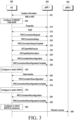
- Steps 365 to 395 in FIG. 3 are procedures related to a handover and will be described in more detail in steps 1605 to 1675 in FIG. 16 below.
- a multicast bearer may refer to a bearer providing a multicast service or a broadcast service, and may indicate a broadcast bearer.
- the multicast service may indicate a service provided only to a terminal registered or authorized in a network.
- the broadcast service may indicate a service provided to an unspecified number of terminals, or to a terminal which is not registered or not authorized in the network.
- a bearer supporting the multicast service or the broadcast service may be referred to as a multicast bearer.
- the MBS service may indicate a multicast service, a broadcast service, or a unicast service for the MBS service, and may be described as the MBS service for convenience of a description.
- the multicast service may indicate an MBS service supported by a Point to Multicast (PTM) scheme or may be supported with the multicast bearer
- the unicast service may indicate an MBS service supported by a Point to Point (PTP) scheme or may be supported with the unicast bearer.
- PTM Point to Multicast
- PTP Point to Point
- the MBS bearer may indicate the multicast bearer or the unicast bearer.
- a Downlink Shared Channel (DL-SCH) described in the disclosure may include or indicate a Common Control Channel (CCCH), a Dedicated Control Channel (DCCH), or a Dedicated Traffic Channel (DTCH).
- CCCH Common Control Channel
- DCCH Dedicated Control Channel
- DTCH Dedicated Traffic Channel
- the bearer, the multicast bearer, or the unicast bearer for the MBS service described in the disclosure may be interpreted as a multicast bearer or a unicast bearer.
- a bearer includes an SRB and a DRB
- the SRB means a signaling radio bearer
- the DRB means a data radio bearer.
- the SRB is mainly used to transmit and receive an RRC message of an RRC layer device
- the DRB is mainly used to transmit and receive pieces of user layer data.
- a UM DRB means a DRB using an RLC layer device operating in a UM mode
- an AM DRB means a DRB using an RLC layer device operating in an AM mode.
- MBS data for the MBS service described in the disclosure may be interpreted as MBS control data (control plane data) for configuration information of an MBS channel, or bearer configuration or service configuration, or MBS user data (user plane data) supporting the MBS service.
- control data control plane data
- bearer configuration or service configuration for configuration information of an MBS channel
- MBS user data user plane data supporting the MBS service.
- a Radio Network Temporary Identifier (RNTI) identifier described in the disclosure is an identifier used for a terminal to monitor a PDCCH in a physical layer device, descramble or check Cyclic Redundancy Check (CRC) of a received PDCCH to identify whether it is an RNTI value configured in the terminal or an RNTI value corresponding to a PDCCH which the terminal intends to receive, and to determine whether it is a PDCCH which the terminal needs to read.
- CRC Cyclic Redundancy Check
- FIGS. 4A to 4D are diagrams illustrating a structure of a bearer configured for an MBS service according to an embodiment of the disclosure. That is, FIGS. 4A to 4D describe a structure of a bearer which a terminal establishes for receiving an MBS service or which a base station or a network may configure to the terminal for the MBS service via system information, an RRC message (e.g., an RRCSetup message, an RRCResume message, an RRCReconfiguration message, an RRCRelease message, or a newly defined RRC message) or a control message for an MBS channel when the base station or the network supports the MBS service to the terminal in an RRC connected mode, an RRC inactive mode, or an RRC idle mode. Bearer structures described in FIGS. 4A to 4D may be extended and applied or configured even when a normal data service is supported.
- RRC message e.g., an RRCSetup message, an RRCResume message, an RRCReconfiguration message,
- a bearer structure configured for the MBS service may have one or a plurality of bearer structures from bearer structures in FIGS. 4A to 4D .
- one or a plurality of structures of the bearer structures in FIGS. 4A to 4D may be promised or designated as default configuration in configuration information of a bearer for the MBS service.
- the bearer structures in FIGS. 4A to 4D may be configured or applied to a terminal or a base station.
- FIG. 4A is a diagram illustrating a first bearer structure for supporting an MBS service according to an embodiment of the disclosure.
- a terminal may configure a bearer structure directly connecting a MAC layer device and a upper MBS application layer device as a bearer for the MBS service. Transmission of HARQ ACK or NACK, or a HARQ retransmission procedure or a HARQ processing procedure of a MAC layer device may not be applied to the first bearer structure.
- the terminal may transfer MBS data (MBS control data or MBS user data) received via a physical layer device or the MAC layer device to a upper MBS application layer device.
- the MBS data may not include a MAC header.
- the MBS data may be distinguished in the MAC layer device even without the MAC header if a separate physical channel or transport channel for the MBS service is configured and a separate transmission resource (a frequency or time resource or a transmission period) is configured.
- a separate transmission resource a frequency or time resource or a transmission period
- the MBS data may be distinguished in the physical layer device or the MAC layer device even without the MAC header when a first RNTI is allocated or determined for the MBS data if the separate physical channel or transport channel for the MBS service is configured, and the separate transmission resource (the frequency or time resource or the transmission period) is configured.
- the first RNTI for the MBS data may be allocated or designated as a 1-1 RNTI for MBS control data (or an MBS control data channel) or a 1-2 RNTI for MBS user data (or an MBS user data channel), respectively.
- the MAC layer device may not basically apply the transmission of HARQ ACK or NACK, the HARQ retransmission procedure, or the HARQ processing procedure to the bearer supporting the MBS service.
- configuration information of an SDAP layer device for the first bearer structure 401a is not configured in the system information, the RRC message, or the control message for the MBS channel, and the SDAP layer device may directly transfer data of the first bearer to the MBS application layer device without processing (for example, bypassing) the data of the first bearer.
- SDAP layer device configuration information for the bearer may be configured in system information, an RRC message (e.g., an RRCSetup message, an RRCResume message, an RRCReconfiguration message, an RRCRelease message, or a newly defined RRC message), or a control message for an MBS channel, or mapping information between a QoS flow and a bearer may be configured or reconfigured.
- Presence/absence of an SDAP header for downlink data or presence/absence of an SDAP header for uplink data may be configured in the SDAP layer device configuration information.
- a reconfiguration or switching procedure between a unicast bearer or a multicast bearer may be supported using the mapping information between the QoS flow and the bearer.
- MBS services may be supported by mapping a QoS flow for the MBS service to the bearer in the SDAP configuration information for the bearer.
- MBS data which may be received or transmitted in the first bearer structure 401a may have a structure 402a or 403a.
- the MBS data which may be received or transmitted in the first bearer structure 401a may have the structure 402a or 403a according to configuration information in the system information, the RRC message (e.g., the RRCSetup message, the RRCResume message, the RRCReconfiguration message, the RRCRelease message, or the newly defined RRC message), or the control message for the MBS channel.
- the RRC message e.g., the RRCSetup message, the RRCResume message, the RRCReconfiguration message, the RRCRelease message, or the newly defined RRC message
- the control message for the MBS channel.
- FIG. 4B is a diagram illustrating a second bearer structure for supporting an MBS service according to an embodiment of the disclosure.
- a terminal may configure an RLC layer device which corresponds to an MBS control data channel, an MBS user data channel, or a logical channel identifier (or an MBS service) of the MBS user data channel and which is connected to a MAC layer device.
- the terminal may configure a bearer structure directly connecting the RLC layer device and a upper MBS application layer device as a bearer for the MBS service. Transmission of HARQ ACK or NACK, or a HARQ retransmission procedure or a HARQ processing procedure of a MAC layer device may not be applied to the second bearer in the second bearer structure 401b.
- the terminal may transfer MBS data (MBS control data or MBS user data) received via a physical layer device or the MAC layer device to a upper MBS application layer device via the RLC layer device.
- MBS data may not include a MAC header. For example, this is because the MBS data may be distinguished in the MAC layer device even without the MAC header if a separate physical channel or transport channel for the MBS service is configured and a separate transmission resource (a frequency or time resource or a transmission period) is configured.
- the MBS data may be distinguished in the physical layer device or the MAC layer device even without the MAC header when a first RNTI is allocated or determined for the MBS data if the separate physical channel or transport channel for the MBS service is configured, and the separate transmission resource (the frequency or time resource or the transmission period) is configured.
- the first RNTI for the MBS data may be allocated or designated as a 1-1 RNTI for MBS control data (or an MBS control data channel) or 1-2 RNTIs for MBS user data (or per MBS user data channel, logical channel identifier, or MBS service), respectively.
- a separate physical channel or transport channel for the MBS service may be configured, or the MBS service may be supported in a DL-SCH used for a normal data service.
- MBS data may include a MAC header, and MBS control data (or an MBS control data channel), MBS user data (or per MBS user data channel, logical channel identifier, or MBS service), or the MBS service may be distinguished based on a logical channel identifier included in the MAC header, or it may be distinguished, demultiplexed, and transferred to each RLC layer device.
- a separate physical channel or transport channel for the MBS service may be configured, or the MBS service may be supported in a DL-SCH used for a normal data service.
- MBS data may be received in the transmission resource, and if the first RNTI for the MBS data is allocated or determined, the MBS data may be received in the transmission resource according to a PDCCH indication with the first RNTI.
- the MBS data may include a MAC header, and MBS control data (or an MBS control data channel), MBS user data (or per MBS user data channel, logical channel identifier, or MBS service), or the MBS service may be distinguished based on a logical channel identifier included in the MAC header, or it may be distinguished, demultiplexed, and transferred to each RLC layer device. That is, for a logical channel, different logical channel identifiers may be configured or defined per MBS control data channel, MBS user data channel, or MBS service, and the MBS service may be supported.
- the RLC layer device configured in the second bearer structure 401b may be configured with a Transparent Mode (TM), and MBS data may not include an RLC header.
- TM Transparent Mode
- an RLC serial number length may not be set in the RLC layer device.
- the RLC layer device may not apply a data processing procedure to the MBS data.
- the RLC layer device configured in the second bearer structure 401b may not apply a procedure for segmenting data or a procedure for reassembling data to the MBS data in the TM mode.
- the RLC layer device configured in the second bearer structure 401b may set an RLC reception window size to 0 or may not operate the RLC reception window.
- the MAC layer device may not basically apply the transmission of HARQ ACK or NACK, the HARQ retransmission procedure, or the HARQ processing procedure to the bearer supporting the MBS service.
- configuration information of an SDAP layer device for the second bearer structure 401b is not configured in the system information, the RRC message, or the control message for the MBS channel, and the SDAP layer device may directly transfer data of the second bearer to the MBS application layer device without processing (for example, bypassing) the data of the second bearer.
- SDAP layer device configuration information for the bearer may be configured in system information, an RRC message (e.g., an RRCSetup message, an RRCResume message, an RRCReconfiguration message, an RRCRelease message, or a newly defined RRC message), or a control message for an MBS channel, or mapping information between a QoS flow and a bearer may be configured or reconfigured.
- Presence/absence of an SDAP header for downlink data or presence/absence of an SDAP header for uplink data may be configured in the SDAP layer device configuration information.
- a reconfiguration or switching procedure between a unicast bearer or a multicast bearer may be supported using the mapping information between the QoS flow and the bearer.
- MBS services may be supported by mapping a QoS flow for the MBS service to the bearer in the SDAP configuration information for the bearer.
- MBS data which may be received or transmitted in the second bearer structure 401b may have a structure 402b.
- the MBS data which may be received or transmitted in the second bearer structure 401b may have the structure 402b according to configuration information in the system information, the RRC message (e.g., the RRCSetup message, the RRCResume message, the RRCReconfiguration message, the RRCRelease message, or the newly defined RRC message), or the control message for the MBS channel.
- the RRC message e.g., the RRCSetup message, the RRCResume message, the RRCReconfiguration message, the RRCRelease message, or the newly defined RRC message
- the control message for the MBS channel.
- FIG. 4C is a diagram illustrating a third bearer structure for supporting an MBS service according to an embodiment of the disclosure.
- a terminal may configure an RLC layer device which corresponds to an MBS control data channel, an MBS user data channel, or a logical channel identifier (or an MBS service) of the MBS user data channel and which is connected to a MAC layer device.
- the terminal may configure a bearer structure directly connecting the RLC layer device and a upper MBS application layer device as a bearer for the MBS service. Transmission of HARQ ACK or NACK, or a HARQ retransmission procedure or a HARQ processing procedure of a MAC layer device may not be applied to the third bearer in the third bearer structure.
- whether the transmission of HARQ ACK or NACK, or the HARQ retransmission procedure or the HARQ processing procedure of the MAC layer device will be performed may be configured with an indicator in system information, an RRC message (e.g., an RRCSetup message, an RRCResume message, an RRCReconfiguration message, an RRCRelease message, or a newly defined RRC message), or a control message for an MBS channel.
- an RRC message e.g., an RRCSetup message, an RRCResume message, an RRCReconfiguration message, an RRCRelease message, or a newly defined RRC message
- an indicator is configured to perform the transmission of HARQ ACK or NACK, or the HARQ retransmission procedure or the HARQ processing procedure in the system information, the RRC message, or the control message for the MBS channel (if an indicator value indicates a specific value or if there is no indicator field), it may be performed.
- the indicator is configured not to perform the transmission of HARQ ACK or NACK, or the HARQ retransmission procedure or the HARQ processing procedure (if the indicator value indicates a specific value or if there is no indicator field), it may not be performed.
- the transmission of HARQ ACK or NACK, or the HARQ retransmission procedure or the HARQ processing procedure may not basically applied to the bearer supporting the MBS service.
- the indicator may be configured for the MBS control data channel, the MBS user data channel, or a logical channel identifier (or an MBS service) or a bearer identifier of the MBS user data channel, respectively.
- an indicator may be configured to perform a HARQ reordering or RLC reordering function (RLC reordering or in-order delivery) for the RLC layer device configured for the MBS control data channel, the MBS user data channel, or the logical channel identifier (or the MBS service) or the bearer identifier of the MBS user data channel in the system information, the RRC message (e.g., the RRCSetup message, the RRCResume message, the RRCReconfiguration message, the RRCRelease message, or the newly defined RRC message), or the control message for the MBS channel.
- RRC message e.g., the RRCSetup message, the RRCResume message, the RRCReconfiguration message, the RRCRelease message, or the newly defined RRC message
- an RLC reception window size may be set to a value (for example, 2 ⁇ (RLC serial number length - 1)) greater than 0 and operated. This is because if a HARQ process or retransmission is performed on the MBS data, an order of data may be mixed, so reordering needs to be performed on the MBS data based on an RLC reception window or based on an RLC serial number, or the MBS service may sequentially be supported in order only when a reordering timer is driven.
- an indicator may be configured not to perform a HARQ reordering or RLC reordering function for the RLC layer device configured for the MBS control data channel, the MBS user data channel, or the logical channel identifier (or the MBS service) or the bearer identifier of the MBS user data channel in the system information, the RRC message (e.g., the RRCSetup message, the RRCResume message, the RRCReconfiguration message, the RRCRelease message, or the newly defined RRC message), or the control message for the MBS channel.
- the RRC message e.g., the RRCSetup message, the RRCResume message, the RRCReconfiguration message, the RRCRelease message, or the newly defined RRC message
- the transmission of HARQ ACK or NACK, the HARQ retransmission procedure, or the HARQ processing procedure is not basically applied to the bearer supporting the MBS service in the MAC layer device, thereby the HARQ reordering or RLC reordering function may not basically performed in the RLC layer device configured for the bearer supporting the MBS service.
- the RLC reception window may not be operated by setting the RLC reception window size to 0.
- the terminal may transfer data always received in the RLC layer device to the upper layer device in an out-of-order delivery method regardless of the order.
- the terminal may transfer MBS data (MBS control data or MBS user data) received via the physical layer device or the MAC layer device to the upper MBS application layer device via the RLC layer device.
- MBS data may include a MAC header.
- a logical identifier included in the MAC header may be set or defined to indicate an MBS control data channel, an MBS user data channel, or each MBS service.
- the physical layer device or the MAC layer device may distinguish whether the MBS data is MBS control data, MBS user data, or data for a certain MBS service based on an RNTI or a logical channel identifier, or may distinguish, demultiplex and transfer it to each RLC layer device.
- the first RNTI for the MBS data may be allocated or designated as a 1-1 RNTI for MBS control data (or an MBS control data channel) or 1-2 RNTIs for MBS user data (or per MBS user data channel, logical channel identifier, or MBS service), respectively.
- a separate physical channel or transport channel for the MBS service may be configured, or the MBS service is supported in a DL-SCH used for a normal data service.
- MBS data may include a MAC header, and MBS control data (or an MBS control data channel), MBS user data (or per MBS user data channel, logical channel identifier, or MBS service), or the MBS service may be distinguished based on a logical channel identifier included in the MAC header, or it may be distinguished, demultiplexed, and transferred to each RLC layer device.
- MBS control data or an MBS control data channel
- MBS user data or per MBS user data channel, logical channel identifier, or MBS service
- MBS service may be distinguished based on a logical channel identifier included in the MAC header, or it may be distinguished, demultiplexed, and transferred to each RLC layer device.
- MBS service may be distinguished based on a logical channel identifier included in the MAC header, or it may be distinguished, demultiplexed, and transferred to each RLC layer device.
- a separate physical channel or transport channel for the MBS service may be configured, or the MBS service is
- MBS data may be received in the transmission resource, and if the first RNTI for the MBS data is allocated or determined, the MBS data may be received in the transmission resource according to a PDCCH indication with the first RNTI.
- the MBS data may include a MAC header, and MBS control data (or an MBS control data channel), MBS user data (or per MBS user data channel, logical channel identifier, or MBS service), or the MBS service may be distinguished based on a logical channel identifier included in the MAC header, or it may be distinguished, demultiplexed, and transferred to each RLC layer device.
- logical channel identifiers may be configured or defined per MBS control data channel, MBS user data channel, or MBS service, and the MBS service may be supported.
- An RLC layer device configured in the third bearer structure may be configured with a TM, a UM, a uni-directional mode of a UM mode, a bi-directional mode of the UM mode, or an AM mode.
- the MBS data may not include an RLC header
- the RLC header may be included.
- the RLC layer device may not apply a data processing procedure to the MBS data (for example, a data segmentation procedure or a reassembly procedure may not be applied), and in the RLC UM mode or AM mode, a data processing procedure may be applied to the MBS data.
- configuration information of an SDAP layer device for the third bearer structure 401c is not configured in the system information, the RRC message, or the control message for the MBS channel, and the SDAP layer device may directly transfer data of the third bearer to the MBS application layer device without processing (for example, bypassing) the data of the third bearer.
- SDAP layer device configuration information for the bearer may be configured in system information, an RRC message (e.g., an RRCSetup message, an RRCResume message, an RRCReconfiguration message, an RRCRelease message, or a newly defined RRC message), or a control message for an MBS channel, or mapping information between a QoS flow and a bearer may be configured or reconfigured. Presence/absence of an SDAP header for downlink data or presence/absence of an SDAP header for uplink data may be configured in the SDAP layer device configuration information. In addition, a reconfiguration or switching procedure between a unicast bearer or a multicast bearer may be supported using the mapping information between the QoS flow and the bearer.
- an RRC message e.g., an RRCSetup message, an RRCResume message, an RRCReconfiguration message, an RRCRelease message, or a newly defined RRC message
- MBS services may be supported by mapping a QoS flow for the MBS service to the bearer in the SDAP configuration information for the bearer.
- MBS data which may be received or transmitted in the third bearer structure 401c may have a structure 402c or 403c.
- the MBS data which may be received or transmitted in the third bearer structure 401c may have the structure 402c or 403c according to configuration information in the system information, the RRC message (e.g., the RRCSetup message, the RRCResume message, the RRCReconfiguration message, the RRCRelease message, or the newly defined RRC message), or the control message for the MBS channel.
- the RRC message e.g., the RRCSetup message, the RRCResume message, the RRCReconfiguration message, the RRCRelease message, or the newly defined RRC message
- the RRC message e.g., the RRCSetup message, the RRCResume message, the RRCReconfiguration message, the RRCRelease message, or the newly defined RRC message
- transmission resource e.g., a time or frequency resource, a transport channel, frequency spacing, and/or the like
- the terminal in the RRC connected mode, the RRC inactive mode, or the RRC idle mode may transmit HARQ ACK or NACK via the configured transmission resource (e.g., a physical transmission resource) after receiving downlink MBS data.
- the configured transmission resource e.g., a physical transmission resource
- the base station may perform retransmission for the MBS data. Alternatively, retransmission may be performed so that all terminals may receive it via the MBS channel.
- the terminal in the RRC connected mode, the RRC inactive mode, or the RRC idle mode may define MAC control information (or RLC control information, PDCP control information, or an RRC message), and may cause the base station to indicate which terminal has not successfully receive data (for example, the MAC control information (or the RLC control information, the PDCP control information, or the RRC message) may be transmitted in the configured transmission resource) by including a terminal identifier, an MBS service identifier, a logical channel identifier, an RNTI identifier, or a bearer identifier into the MAC control information (or the RLC control information, the PDCP control information, or the RRC message) to transmit the MAC control information.
- MAC control information or RLC control information, PDCP control information, or an RRC message
- the base station may perform retransmission for the MBS data only to a terminal in the RRC connected mode, the RRC idle mode, or the RRC inactive mode which transmits NACK in the transmission resource, or which indicates that successful reception is not achieved.
- the base station may perform the retransmission for the MBS data.
- retransmission may be performed so that all terminals may receive it via the MBS channel.
- FIG. 4D is a diagram illustrating a fourth bearer structure for supporting an MBS service according to an embodiment of the disclosure.
- a terminal may configure an RLC layer device which is connected to a MAC layer device and which corresponds to an MBS control data channel, an MBS user data channel, or a logical channel identifier (or an MBS service) of the an MBS user data channel.
- Each RLC layer device may be configured for each MBS service or each MBS service type (e.g., a multicast service (PTM, and Point to Multicast MBS service) or a unicast service (Point to Point MBS service)), and may be configured as in 401d, 402d, or 403d to be connected to one base station (or one MAC layer device) or a plurality of base stations (or a plurality of MAC layer devices) to receive a service.
- a PDCP layer device connected to each RLC layer device or a plurality of RLC layer devices may be configured, and a bearer structure directly connecting the PDCP layer device to an upper MBS application layer device may be configured as a bearer for the MBS service.
- a base station configures a first RLC layer device for a multicast service and a second RLC layer device for a unicast service in one PDCP layer device, thereby facilitating switching (PTM to PTP switching or PTP to PTM switching) or change between a multicast service scheme and a unicast scheme.
- the base station may transmit MBS service data to the first RLC layer device or the second RLC layer device.
- An indicator (e.g., an indicator indicating PTP or PTM, an MBS service identifier, an indicator indicating a primary RLC device, a cell group identifier, or a logical channel identifier) may be configured in an RRC message so that the first RLC layer device (e.g., an RLC layer device for a multicast service, a primary RLC layer device, or a secondary RLC layer device) or the second RLC layer device (e.g., an RLC layer device for a unicast service, a primary RLC layer device, or a secondary RLC layer device) may be distinguished, or the first RLC layer device or the second RLC layer device may be configured as a primary RLC layer device or a secondary RLC layer device, respectively to be distinguished.
- the first RLC layer device e.g., an RLC layer device for a multicast service, a primary RLC layer device, or a secondary RLC layer device
- the second RLC layer device e.g., an RLC layer device for
- a base station may configure a first RLC layer device for a multicast service and a second RLC layer device for a unicast service in one PDCP layer device, and facilitate switching or change between a multicast service scheme and a unicast scheme.
- the base station may transmit MBS service data to the first RLC layer device or the second RLC layer device, and may configure the terminal to receive MBS service data from different base stations by connecting the first RLC layer device or the second RLC layer device with a MAC or physical layer device which corresponds to different base stations (a first base station or a second base station), respectively, like a dual access technology.
- An indicator (e.g., an indicator indicating PTP or PTM, an MBS service identifier, an indicator indicating a primary RLC device, a cell group identifier, or a logical channel identifier) may be configured in an RRC message so that the first RLC layer device (e.g., an RLC layer device for a multicast service, a primary RLC layer device, or a secondary RLC layer device) or the second RLC layer device (e.g., an RLC layer device for a unicast service, a primary RLC layer device, or a secondary RLC layer device) may be distinguished.
- the first RLC layer device or the second RLC layer device may be configured as a primary RLC layer device or a secondary RLC layer device, respectively to be distinguished.
- the fourth bearer structure may configure a plurality of RLC devices in one PDCP layer device for each MBS service or each MBS service type (e.g., a multicast service or a unicast service) to support an MBS service.
- RLC layer devices configured in the fourth bearer structure may be configured in with a UM mode, an AM mode, or a TM mode.
- an RLC layer device supporting a multicast service (PTM) may be configured with a UM mode
- an RLC layer device supporting a unicast service (PTP) may be configured with a UM mode or an AM mode.
- transmission of HARQ ACK or NACK, a HARQ retransmission procedure, or a HARQ processing procedure of a MAC layer device may not be applied to the fourth bearer.
- whether the transmission of HARQ ACK or NACK, or the HARQ retransmission procedure or the HARQ processing procedure of the MAC layer device will be performed may be configured via an indicator in system information, an RRC message (e.g., an RRCSetup message, an RRCResume message, an RRCReconfiguration message, an RRCRelease message, or a newly defined RRC message), or a control message for an MBS channel.
- an RRC message e.g., an RRCSetup message, an RRCResume message, an RRCReconfiguration message, an RRCRelease message, or a newly defined RRC message
- an indicator is configured to perform the transmission of HARQ ACK or NACK, or the HARQ retransmission procedure or the HARQ processing procedure in the system information, the RRC message, or the control message for the MBS channel (if an indicator value indicates a specific value or if there is no indicator field), it may be performed.
- the indicator is configured not to perform the transmission of HARQ ACK or NACK, or the HARQ retransmission procedure or the HARQ processing procedure (if the indicator value indicates a specific value or if there is no indicator field), it may not be performed, or in the MAC layer device, the transmission of HARQ ACK or NACK, or the HARQ retransmission procedure or the HARQ processing procedure may not basically applied to the bearer supporting the MBS service.
- the indicator may be configured for the MBS control data channel, the MBS user data channel, or a logical channel identifier (or an MBS service) or a bearer identifier of the MBS user data channel, respectively.
- an indicator may be configured to perform a HARQ reordering or RLC reordering function for the RLC layer device configured for the MBS control data channel, the MBS user data channel, or the logical channel identifier (or the MBS service) or the bearer identifier of the MBS user data channel in the system information, the RRC message (e.g., the RRCSetup message, the RRCResume message, the RRCReconfiguration message, the RRCRelease message, or the newly defined RRC message), or the control message for the MBS channel.
- the RRC message e.g., the RRCSetup message, the RRCResume message, the RRCReconfiguration message, the RRCRelease message, or the newly defined RRC message
- an RLC reception window size may be set to a value (for example, 2 ⁇ (RLC serial number length - 1)) greater than 0 and operated. This is because if a HARQ process or retransmission is performed on the MBS data, an order of data may be mixed, so reordering is performed on the MBS data based on an RLC reception window or based on an RLC serial number, or the MBS service may sequentially be supported in order only when a reordering timer is driven.
- a value for example, 2 ⁇ (RLC serial number length - 1)
- an indicator may be configured not to perform a HARQ reordering or RLC reordering function for the RLC layer device configured for the MBS control data channel, the MBS user data channel, or the logical channel identifier (or the MBS service) or the bearer identifier of the MBS user data channel in the system information, the RRC message (e.g., the RRCSetup message, the RRCResume message, the RRCReconfiguration message, the RRCRelease message, or the newly defined RRC message), or the control message for the MBS channel.
- the RRC message e.g., the RRCSetup message, the RRCResume message, the RRCReconfiguration message, the RRCRelease message, or the newly defined RRC message
- the transmission of HARQ ACK or NACK, the HARQ retransmission procedure, or the HARQ processing procedure is not basically applied to the bearer supporting the MBS service in the MAC layer device, thereby the HARQ reordering or RLC reordering function may not basically performed in the RLC layer device configured for the bearer supporting the MBS service.
- the MAC layer device does not perform the transmission of HARQ ACK or NACK, the HARQ retransmission procedure, or the HARQ processing procedure, or if it is configured not to perform, the RLC reception window of an RLC layer device of the MBS bearer may not be operated by setting the RLC reception window size to 0.
- the terminal may transfer data always received in the RLC layer device to the upper layer device in an out-of-order delivery method regardless of the order.
- the terminal may transfer MBS data (MBS control data or MBS user data) received via the physical layer device or the MAC layer device to the upper MBS application layer device via the RLC layer device or the PDCP layer device.
- the MBS data may include a MAC header.
- a logical channel identifier included in the MAC header may be set or defined to indicate an MBS control data channel, an MBS user data channel, or each MBS service.
- the physical layer device or the MAC layer device may distinguish whether the MBS data is MBS control data, MBS user data, or data for a certain MBS service based on an RNTI or a logical channel identifier, or may distinguish, demultiplex and transfer it to each RLC layer device.
- the first RNTI for the MBS data may be allocated or designated as a 1-1 RNTI for MBS control data (or an MBS control data channel) or 1-2 RNTIs for MBS user data (or per MBS user data channel, logical channel identifier, or MBS service), respectively.
- a separate physical channel or transport channel for the MBS service may be configured, or the MBS service is supported in a DL-SCH used for a normal data service, or if a separate transmission resource (a frequency or time resource or a transmission period) is configured
- MBS data may include a MAC header, and MBS control data (or an MBS control data channel), MBS user data (or per MBS user data channel, logical channel identifier, or MBS service), or the MBS service may be distinguished based on a logical channel identifier included in the MAC header, or it may be distinguished, demultiplexed, and transferred to each RLC layer device.
- a separate physical channel or transport channel for the MBS service may be configured, or the MBS service may be supported in a DL-SCH used for a normal data service. If a separate transmission resource (a frequency or time resource or a transmission period) is configured, MBS data may be received in the transmission resource, and if the first RNTI for the MBS data is allocated or determined, the MBS data may be received in the transmission resource according to a PDCCH indication with the first RNTI.
- the MBS data may include a MAC header.
- MBS control data (or an MBS control data channel), MBS user data (or per MBS user data channel, logical channel identifier, or MBS service), or the MBS service may be distinguished based on a logical channel identifier included in the MAC header, or it may be distinguished, demultiplexed, and transferred to each RLC layer device. That is, for a logical channel, different logical channel identifiers may be configured or defined per MBS control data channel, MBS user data channel, or MBS service, and the MBS service may be supported.
- An RLC layer device configured in the fourth bearer structure may be configured with one of a TM mode, a UM mode, a uni-directional mode of a UM mode, a bi-directional mode of the UM mode, or AM modes.
- the MBS data may not include an RLC header.
- the RLC header may be included.
- the RLC layer device may not apply a data processing procedure to the MBS data (for example, a data segmentation procedure or a reassembly procedure may not be performed).
- a data processing procedure may be applied to the MBS data.
- an RLC layer device may be configured with a TM mode in system information, an RRC message (e.g., an RRCSetup message, an RRCResume message, an RRCReconfiguration message, an RRCRelease message, or a newly defined RRC message), or a control message for an MBS channel, thereby reducing overhead for MBS data (for example, overhead may be reduced by not using an RLC header).
- RRC message e.g., an RRCSetup message, an RRCResume message, an RRCReconfiguration message, an RRCRelease message, or a newly defined RRC message
- a control message for an MBS channel thereby reducing overhead for MBS data (for example, overhead may be reduced by not using an RLC header).
- an out-of-order delivery function may be configured in a PDCP layer device in system information, an RRC message (e.g., an RRCSetup message, an RRCResume message, an RRCReconfiguration message, an RRCRelease message, or a newly defined RRC message), or a control message for an MBS channel, thereby preventing transmission delay of MBS data.
- RRC message e.g., an RRCSetup message, an RRCResume message, an RRCReconfiguration message, an RRCRelease message, or a newly defined RRC message
- a PDCP layer device is configured to basically (for example, an out-of-order delivery indicator is always set to True) performs an out-of-order delivery function or to set a PDCP reordering timer value to 0, and not to perform a reordering procedure even if a gap of a PDCP serial number (or a COUNT value) occurs (received data is transferred to a upper layer device immediately after data processing (e.g., a PDCP header removal or decoding procedure, an integrity verification procedure, or a header decompression procedure) of a receiving PDCP layer device without waiting for a data of a PDCP sequence number (or a COUNT value) corresponding to the gap
- the reordering timer is triggered due to the gap in the PDCP serial number (or the COUNT value), and data corresponding to the gap needs to be waited for as long as the reordering timer value, so it may cause transmission delay.
- the PDCP layer device may basically perform the PDCP reordering function.
- the PDCP layer device may determine a size of a reception window (e.g., a length of a PDCP serial number 16 bits, and a window size is 2 ⁇ (16-1)) based on the length of the PDCP serial number, and drive a reordering timer.
- SDAP layer device configuration information may be configured in system information, an RRC message (e.g., an RRCSetup message, an RRCResume message, an RRCReconfiguration message, an RRCRelease message, or a newly defined RRC message), or a control message for an MBS channel, or mapping information between a QoS flow and a bearer may be configured or reconfigured.
- an RRC message e.g., an RRCSetup message, an RRCResume message, an RRCReconfiguration message, an RRCRelease message, or a newly defined RRC message
- Presence/absence of an SDAP header for downlink data or presence/absence of an SDAP header for uplink data may be configured in the SDAP layer device configuration information.
- a reconfiguration or switching procedure between a unicast bearer or a multicast bearer configured in the fourth bearer structure 402d or 403d may be supported using the mapping information between the QoS flow and the bearer.
- a reconfiguration or switching procedure between a unicast bearer having the fourth bearer structure 401d or a multicast bearer having the fourth bearer structure 401d may be supported.
- the SDAP layer device may directly transfer data of the fourth bearer to the MBS application layer device without processing it (e.g., by bypassing it).
- MBS services may be supported by mapping a QoS flow for the MBS service to the bearer in the SDAP configuration information for the bearer.
- MBS data which may be received or transmitted in the fourth bearer structure may have a structure 404d, 405d, 406d, or 407d.
- the MBS data which may be received or transmitted in the fourth bearer structure may have the structure 404d, 405d, 406d, or 407d according to configuration information in the system information, the RRC message (e.g., the RRCSetup message, the RRCResume message, the RRCReconfiguration message, the RRCRelease message, or the newly defined RRC message), or the control message for the MBS channel.
- the RRC message e.g., the RRCSetup message, the RRCResume message, the RRCReconfiguration message, the RRCRelease message, or the newly defined RRC message
- the RRC message e.g., the RRCSetup message, the RRCResume message, the RRCReconfiguration message, the RRCRelease message, or the newly defined RRC message
- transmission resource e.g., a time or frequency resource, a transport channel, frequency spacing, and/or the like
- the terminal in the RRC connected mode, the RRC inactive mode, or the RRC idle mode may receive downlink MBS data and transmit HARQ ACK or NACK via the configured transmission resource (e.g., a physical transmission resource).
- the configured transmission resource e.g., a physical transmission resource.
- the base station may perform retransmission for the MBS data. Alternatively, retransmission may be performed so that all terminals may receive it via the MBS channel.
- the terminal in the RRC connected mode, the RRC inactive mode, or the RRC idle mode may receive downlink MBS data, define MAC control information (or RLC control information, PDCP control information, or an RRC message), and may indicate which terminal has not successfully receive data to the base station receiving MAC control information by transmitting the MAC control information including at least one of a terminal identifier, an MBS service identifier, a logical channel identifier, an RNTI identifier, or a bearer identifier (for example, the terminal may transmit the MAC control information in a configured transmission resource).
- MAC control information or RLC control information, PDCP control information, or an RRC message
- the base station may perform retransmission for the MBS data only to a terminal in the RRC connected mode, the RRC idle mode, or the RRC inactive mode which transmits NACK in the transmission resource, or which indicates that successful reception is not achieved. If the base station detects the at least one NACK in the transmission resource or detects that the at least one terminal has transmitted the NACK, the base station may perform the retransmission for the MBS data. Retransmission may be performed so that all terminals may receive it via the MBS channel.
- a terminal When a terminal receives system information, when the terminal intends to receive a service of interest, when the terminal has the service of interest, when the terminal determines the service of interest, when the terminal exists in or enters a cell or area supporting an MBS service in the system information, when the terminal configures or connects to the MBS service (or session), or when configuration information or bearer configuration information for the MBS service is received or broadcasted via the system information, an RRC message (e.g., an RRCSetup message, an RRCResume message, an RRCReconfiguration message, an RRCRelease message, or a newly defined new RRC message), or a control message for an MBS channel (for example, transmitted on an MBS control data channel), the terminal may configure a unicast bearer, a multicast bearer, or an MBS bearer, which has a bearer structure in FIGS. 4A to 4D , for receiving the MBS service.
- RRC message e.g., an RRCSetup message,
- the base station may configure a first RLC layer device for a multicast service and a second RLC layer device for a unicast service in one PDCP layer device.
- the base station may support the MBS service to the terminal while dynamically switching to a multicast scheme or a unicast scheme in consideration of at least one of a transmission resource of the base station, a scheduling resource, or mobility of the terminal, so a service with low transmission delay or with no or low data loss may be supported.
- pieces of MBS service data received in the second RLC layer device for a unicast service may include pieces of data (e.g., data having a logical channel identifier corresponding to the unicast service, data received in a transmission resource allocated for the unicast service, or data received according to DCI indication of a PDCCH scrambled with an RNTI identifier for the unicast service) received in a transmission resource for supporting the unicast service of each terminal.
- pieces of data e.g., data having a logical channel identifier corresponding to the unicast service, data received in a transmission resource allocated for the unicast service, or data received according to DCI indication of a PDCCH scrambled with an RNTI identifier for the unicast service
- One terminal may receive the pieces of MBS service data in the same transmission resource, and receive and process the pieces of MBS service data in a second RLC layer device for the unicast service configured in the one terminal.
- each terminal may receive unicast data for each terminal in different transmission resources (a transmission resource for each terminal), not the same transmission resource.
- different terminals may receive data (e.g., data having a logical channel identifier corresponding to the unicast service of the terminal, data received in a transmission resource allocated for the unicast service of the terminal, or data received according to DCI indication of a PDCCH scrambled with an RNTI identifier for the unicast service of the terminal) for each terminal in each transmission resource allocated to receive different unicast services, respectively, and process the data in the second RLC layer device for the unicast service configured in each terminal.
- data e.g., data having a logical channel identifier corresponding to the unicast service of the terminal, data received in a transmission resource allocated for the unicast service of the terminal, or data received according to DCI indication of a PDCCH scrambled with an RNTI identifier for the unicast service of the terminal
- the base station may transmit the same MBS service data to the plurality of terminals via one transmission resource in a multicast scheme (each terminal may receive the MBS service data in an RLC layer device for the multicast service (or an RLC layer device configured with a logical channel identifier corresponding to the multicast service)).
- the base station may transmit MBS service data to each terminal in different transmission resources in a unicast scheme (each terminal may receive the MBS service data in an RLC layer device for the unicast service (or an RLC layer device configured with a logical channel identifier corresponding to the unicast service)).
- the MBS service is provided to the plurality of terminals in the multicast scheme, a transmission resource may be saved and the transmission resource may be efficiently used. Meanwhile, if the MBS service is provided to each terminal in the unicast scheme, the MBS service which satisfies a QoS or requirement requested by each terminal may be supported.
- the base station may transmit an individual control message or request message (e.g., whether the MBS service is received, the preference of the MBS service, whether the MBS service is currently received, whether an MBS service type is switched (e.g., switching from PTM to PTP or from PTP to PTM), or a frequency measurement result request)) to each terminal receiving the MBS service via an RLC layer device for the unicast service (an RLC layer device configured with a logical channel identifier corresponding to the unicast service) in a each transmission resource allocated to each terminal, thereby individually controlling and scheduling each terminal.
- an individual control message or request message e.g., whether the MBS service is received, the preference of the MBS service, whether the MBS service is currently received, whether an MBS service type is switched (e.g., switching from PTM to PTP or from PTP to PTM), or a frequency measurement result request)
- an RLC layer device for the unicast service an RLC layer device configured with a logical channel identifier corresponding to
- the base station may transmit a duplicate MBS data service to terminals for which the fourth bearer structure 401d, 402d, or 403d has been configured via the RLC layer device for the multicast service (the RLC layer device configured with the logical channel identifier corresponding to the multicast service) or the RLC layer device for the unicast service (the RLC layer device configured with the logical channel identifier corresponding to the unicast service), thereby increasing reliability for the MBS service of the terminal and reducing the possibility of data loss.
- packet duplicate transmission may be performed in a upper layer device (e.g., a PDCP layer device).
- the terminal may determine that changing from the unicast service (PTP) to the multicast service (PTM) is indicated from the base station. If data is received in the RLC layer device for the unicast service configured in the MBS bearer, the terminal may determine that changing from the multicast service (PTM) to the unicast service (PTP) is indicated from the base station (UE autonomous MBS bearer switching).
- PTP unicast service
- PTM multicast service
- the terminal may perform the following procedures for the MBS bearer in order to continue to receive the MBS service without error or data loss or prevent a problem in a reception window operation.
- the terminal may not perform an initialization procedure on window variables (e.g., RX_NEXT (a variable indicating a COUNT value of data (a PDCP SDU) expected to be received next), RX_DELIV (a variable indicating a COUNT value of first data (a PDCP SDU) not transferred to a upper layer device, or data still waiting to be received), or RX_REORD (a variable indicating a next COUNT value (or a COUNT value incremented by 1) of a COUNT value of data (PDCP data PDU) triggering a PDCP reordering timer, or may use the PDCP reordering timer as it is without initializing the PDCP reordering timer.
- window variables e.g., RX_NEXT (a variable indicating a COUNT value of data (a PDCP SDU) expected to be received next)
- RX_DELIV a variable indicating a COUNT value of first data (a PDCP SDU) not
- information e.g., a PDCP status report
- information about data which is retransmitted or is not received is transmitted to the base station to recover data loss, thereby minimizing data loss because a COUNT value (or a PDCP serial number) of the data by the window variables is maintained if the window variables are not initialized or the PDCP reordering timer is not initialized (if it is running, it is kept running) and then is used as it is.
- the terminal may perform a PDCP re-establishment procedure or a PDCP data recovery procedure in the PDCP layer device, initialize the window variables, or stop (or initializes) the PDCP reordering timer, and perform data processing on stored (or received) data and transfer it to the upper layer device.
- the window variables may be initialized to a value of 0, or in order for the base station to easily manage the window variables (for example, in order for the terminal to synchronize the window variables based on received data even though the base station does not initialize the window variables), the window variables may be initialized based on received data.
- the RX_NEXT variable may be initialized to a combination of a PDCP serial number of data (a PDCP data PDU or a PDCP SDU) firstly received after a change indication from a multicast service (PTM) to a unicast service (PTP) + 1 or an HFN value initialized to 0 (or a previously used HFN value, an HFN value determined by terminal implementation, or an HFN value included in the change indication).
- PTM multicast service
- PTP unicast service
- the RX_DELIV variable may be initialized to the initialized RX_NEXT value or the combination of the PDCP serial number of the data (the PDCP data PDU or the PDCP SDU) firstly received after the change indication + 1 or the HFN value initialized to 0 (or the previously used HFN value, the HFN value determined by the terminal implementation, or the HFN value included in the change indication).
- the RX_REORD value may be initialized to the initialized RX_NEXT value or the combination of the PDCP serial number of the data (the PDCP data PDU or the PDCP SDU) firstly received after the change indication + 1 or the HFN value initialized to 0 (or the previously used HFN value, the HFN value determined by the terminal implementation, or the HFN value included in the change indication).
- initialization for the RX_REORD variable may be omitted so that the reordering timer is driven.
- the RX_DELIV may be initialized to a value obtained by subtracting a reception window size (or half of the reception window size) from the RX_NEXT value and adding 1 thereto.
- the window variables may initialized to each initialization value (reference values or initial values) for the variables included in the indication information (an RRC message, system information, MAC control information, or PDCP control data) indicated by the base station.
- the terminal may report to the base station whether data has been successfully received, and the base station may configure a PDCP status report to transmit the PDCP status report to an RLC layer device for a unicast service (or an RLC layer device configured with a logical channel identifier which corresponds to the unicast service) in order to perform retransmission for reducing loss.
- the base station may retransmit data via the RLC layer device for the unicast service based on the PDCP status report.
- the base station may easily distinguish which terminal the PDCP status report is for. In addition, if the base station performs retransmission via the RLC layer device for the unicast service, the base station may prevent waste of a transmission resource by performing the retransmission via an individual transmission resource. In another embodiment, the terminal may transmit a PDCP status report in an RLC layer device for multicast.
- the terminal may report to the base station whether data has been successfully received, and the base station may configure a PDCP status report to transmit the PDCP status report to an RLC layer device for a multicast service (or an RLC layer device configured with a logical channel identifier which corresponds to the multicast service) in order to perform retransmission for reducing loss.
- the base station may retransmit data via an RLC layer device for the multicast service or the unicast service based on the PDCP status report. If the terminal transmits the PDCP status report via the RLC layer device for the multicast service, the base station may easily detect PDCP status reports of all terminals.
- the terminal may still receive data via the RLC layer device for the multicast service in the fourth bearer structure. This is because the terminal may receive data transmitted late.
- the RLC layer device may be released or re-established (initialization of window variables or discard of stored divided data), thereby facilitating window variable synchronization of the RLC layer device in the base station and quickly discarding unnecessary data.
- the terminal may not perform an initialization procedure on the window variables (for example, in a case of UM mode, RX_Next_Reassembly (a variable indicating the smallest (or the fastest) RLC serial number value which is still under consideration for reassembly), RX_Timer_Trigger (a variable indicating an RLC serial number which is 1 greater than an RLC serial number which triggers the RLC reassembly timer, or which is after the RLC serial number which triggers the RLC reassembly timer), or RX_Next_Highest (a variable indicating an RLC serial number which is 1 greater than an RLC serial number which is the highest among received data (UMD PDUs), or which is after the RLC serial number which is the highest among the received data), or for example, in a case of AM mode, RX_Next (a variable indicating an RLC serial number which is 1 greater than an RLC serial number of the last completely received data (an RLC SDU) in sequence, or which is after the RLC
- the terminal may perform the RLC re-establishment (or establishment) procedure, initialize the window variables, or stop (or initialize) the RLC reassembly timer in the RLC layer device.
- the window variables may be initialized to a value of 0, or in order for the base station to easily manage the window variables (for example, in order for the terminal to synchronize the window variables based on received data even though the base station does not initialize the window variables), the window variables may be initialized based on received data. For example, in the case of UM mode, because an RLC serial number is included only for divided data, complete data without an RLC serial number may be directly processed and transferred to the upper layer device, and a window variable may be updated based on the RLC serial number of the received divided data.
- RX_Next_Reassembly may be initialized to an RLC serial number of data (an RLC SDU, a UMD PDU, or an RLC SDU segment) which is received first after the change indication and includes the RLC serial number.
- the RX_Next _Highest may be initialized to the RLC serial number of the data (the RLC SDU, the UMD PDU, or the RLC SDU segment) which is received first after the change indication and includes the RLC serial number.
- the RX_Timer_Trigger may be initialized to the RLC serial number of the data (the RLC SDU, the UMD PDU, or the RLC SDU segment) which is received first after the change indication and includes the RLC serial number.
- variable initialization may be omitted.
- an RLC serial number is included for all data (RLC data PDU or an RLC SDU), so the RX_Next, the RX_Next_Status_Trigger, or the RX_Highest_Status may be initialized to the RLC serial number of the data (the RLC SDU, the UMD PDU, or the RLC SDU segment) which is received first after the change indication and includes the RLC serial number.
- the RX_Next_Status_Trigger variable or the RX_Highest_Status variable does not have a significant effect on window operation (it causes unnecessary processing), so variable initialization may be omitted.
- the window variables may initialized to each initialization value (reference values or initial values) for the variables included in the change indication information (an RRC message, system information, MAC control information, or PDCP control data) indicated by the base station.
- an RLC re-establishment procedure may be performed to minimize complexity of an ARQ operation for an RLC layer device configured with an RLC AM mode.
- the terminal may start receiving data in the RLC layer device for the unicast service (or the RLC layer device configured with the logical channel identifier which corresponds to the unicast service).
- the terminal may perform the following procedures in order to continue to receive the MBS service without error or data loss or prevent a problem in a reception window operation.
- the terminal may not perform an initialization procedure on window variables (e.g., RX_NEXT (a variable indicating a COUNT value of data (a PDCP SDU) expected to be received next), RX_DELIV (a variable indicating a COUNT value of first data (a PDCP SDU) not transferred to a upper layer device, or data still waiting to be received), or RX_REORD (a variable indicating a next COUNT value (or a COUNT value incremented by 1) of a COUNT value of data (PDCP data PDU) triggering a PDCP reordering timer, or may use the PDCP reordering timer as it is without initializing the PDCP reordering timer.
- window variables e.g., RX_NEXT (a variable indicating a COUNT value of data (a PDCP SDU) expected to be received next)
- RX_DELIV a variable indicating a COUNT value of first data (a PDCP SDU) not
- information e.g., a PDCP status report
- information about data which is retransmitted or is not received is transmitted to the base station to recover data loss, thereby minimizing data loss because a COUNT value (or a PDCP serial number) of the data by the window variables is maintained if the window variables are not initialized or the PDCP reordering timer is not initialized (if it is running, it is kept running) and then is used as it is.
- the terminal may perform a PDCP re-establishment procedure or a PDCP data recovery procedure in the PDCP layer device, initialize the window variables, or stop (or initializes) the PDCP reordering timer, and perform data processing on stored (or received) data and transfer it to the upper layer device.
- the window variables may be initialized to a value of 0, or in order to easily manage the base station window variables (for example, in order for the terminal to synchronize the window variables based on received data even though the base station does not initialize the window variables), the window variables may be initialized based on received data.
- the RX_NEXT variable may be initialized to a combination of a PDCP serial number of data (a PDCP data PDU or a PDCP SDU) firstly received after the indication + 1 or an HFN value initialized to 0 (or a previously used HFN value, an HFN value determined by terminal implementation, or an HFN value included in the change indication).
- the RX_DELIV variable may be initialized to the initialized RX_NEXT value or the combination of the PDCP serial number of the data (the PDCP data PDU or the PDCP SDU) firstly received after the change indication + 1 or the HFN value initialized to 0 (or the previously used HFN value, the HFN value determined by the terminal implementation, or the HFN value included in the change indication).
- the RX _REORD value may be initialized to the initialized RX_NEXT value or the combination of the PDCP serial number of the data (the PDCP data PDU or the PDCP SDU) firstly received after the change indication + 1 or the HFN value initialized to 0 (or the previously used HFN value, the HFN value determined by the terminal implementation, or the HFN value included in the change indication).
- initialization for the RX _REORD variable may be omitted so that the reordering timer is driven.
- the RX _DELIV may be initialized to a value obtained by subtracting a reception window size (or half of the reception window size) from the RX _NEXT value and adding 1 thereto.
- the window variables may initialized to each initialization value (reference values or initial values) for the variables included in the change indication information (an RRC message, system information, MAC control information, or PDCP control data) indicated by the base station.
- the terminal may report to the base station whether data has been successfully received, and the base station may configure a PDCP status report to transmit the PDCP status report to an RLC layer device for a unicast service (or an RLC layer device configured with a logical channel identifier which corresponds to the unicast service) in order to perform retransmission for reducing loss.
- the base station may retransmit data via the RLC layer device for the unicast service based on the PDCP status report.
- the base station may easily distinguish which terminal the PDCP status report is for. In addition, if the base station performs retransmission via the RLC layer device for the unicast service, the base station may prevent waste of a transmission resource by performing the retransmission via an individual transmission resource. In another embodiment, the terminal may transmit a PDCP status report in an RLC layer device for multicast.
- the terminal may report to the base station whether data has been successfully received, and the base station may configure a PDCP status report to transmit the PDCP status report to an RLC layer device for a multicast service (or an RLC layer device configured with a logical channel identifier which corresponds to the multicast service) in order to perform retransmission for reducing loss.
- the base station may retransmit data via an RLC layer device for the multicast service or the unicast service based on the PDCP status report. If the terminal transmits the PDCP status report via the RLC layer device for the multicast service, the base station may easily detect PDCP status reports of all terminals.
- the terminal may still receive data via the RLC layer device for the multicast service in the fourth bearer structure. This is because the terminal may receive data transmitted late.
- the RLC layer device may be released or re-established (initialization of window variables or discard of stored divided data), thereby facilitating window variable synchronization of the RLC layer device in the base station and quickly discarding unnecessary data.
- the terminal may not perform an initialization procedure on the window variables (for example, in a case of UM mode, RX_Next_Reassembly (a variable indicating the smallest (or the fastest) RLC serial number value which is still under consideration for reassembly), RX_Timer_Trigger (a variable indicating an RLC serial number which is 1 greater than an RLC serial number which triggers the RLC reassembly timer, or which is after the RLC serial number which triggers the RLC reassembly timer), or RX_Next_Highest (a variable indicating an RLC serial number which is 1 greater than an RLC serial number which is the highest among received data (UMD PDUs), or which is after the RLC serial number which is the highest among the received data), or for example, in a case of AM mode, RX_Next (a variable indicating an RLC serial number which is 1 greater than an RLC serial number of the last completely received data (an RLC SDU) in sequence, or which is after the RLC
- the terminal may perform the RLC re-establishment (or establishment) procedure, initialize the window variables, or stop (or initialize) the RLC reassembly timer in the RLC layer device.
- the window variables may be initialized to a value of 0, or in order for the base station to easily manage the window variables (for example, in order for the terminal to synchronize the window variables based on received data even though the base station does not initialize the window variables), the window variables may be initialized based on received data. For example, in the case of UM mode, because an RLC serial number is included only for divided data, complete data without an RLC serial number may be directly processed and transferred to the upper layer device, and a window variable may be updated based on the RLC serial number of the received divided data.
- RX_Next_Reassembly may be initialized to an RLC serial number of data (an RLC SDU, a UMD PDU, or an RLC SDU segment) which is received first after the change indication and includes the RLC serial number.
- the RX_Next _Highest may be initialized to the RLC serial number of the data (the RLC SDU, the UMD PDU, or the RLC SDU segment) which is received first after the change indication and includes the RLC serial number.
- the RX_Timer_Trigger may be initialized to the RLC serial number of the data (the RLC SDU, the UMD PDU, or the RLC SDU segment) which is received first after the change indication and includes the RLC serial number.
- variable initialization may be omitted.
- an RLC serial number is included for all data (RLC data PDU or an RLC SDU), so the RX_Next, the RX_Next_Status_Trigger, or the RX_Highest_Status may be initialized to the RLC serial number of the data (the RLC SDU, the UMD PDU, or the RLC SDU segment) which is received first after the indication and includes the RLC serial number.
- the RX_Next_Status_Trigger variable or the RX_Highest_Status variable does not have a significant effect on window operation (it causes unnecessary processing), so variable initialization may be omitted.
- the window variables may initialized to each initialization value (reference values or initial values) for the variables included in the change indication information (an RRC message, system information, MAC control information, or PDCP control data) indicated by the base station.
- an RLC re-establishment procedure may be performed to minimize complexity of an ARQ operation for an RLC layer device configured with an RLC AM mode.
- the terminal may start receiving data via the RLC layer device for the multicast service (or the RLC layer device configured with the logical channel identifier which corresponds to the unicast service).
- the fourth bearer structure 401d, 402d, or 403d may be effectively used to support an MBS service with no data loss or little data loss even in a handover procedure.
- the terminal when the terminal performs a handover procedure to the target base station according to indication (e.g., a handover command message (RRCReconfiguration message)) of the source base station while receiving an MBS service (a multicast service or a unicast service) from the source base station via an MBS bearer for which the fourth bearer structure is configured, the terminal may maintain the fourth bearer structure for the MBS bearer, or the MBS bearer may be reconfigured with the fourth bearer structure, or may be newly configured.
- indication e.g., a handover command message (RRCReconfiguration message)
- MBS service a multicast service or a unicast service
- the terminal may reconfigure the MBS bearer with the structure 401d, 402d, or 403d or configure new MBS bearer.
- the terminal may perform the following procedures.
- the terminal receives the handover command message (the RRCReconfiguration message)(e.g., an RRC message including a reconfigurationWithsync indicator) from the source base station.
- the handover command message includes configuration information for configuring or reconfiguring an MBS bearer, or includes a PDCP layer device reestablishment indicator (reestablishPDCP) for the MBS bearer, or includes a PDCP layer device recovery indicator (recoverPDCP) for the MBS bearer, or if it indicates to reconfigure the PDCP layer device for the MBS bearer, or if the handover command message includes indication to re-establish or release a certain RLC layer device for the MBS bearer, the terminal may perform the following procedures for the MBS bearer in order to continuously receive the MBS service without error or data loss or to prevent a problem in a reception window operation.
- reestablishPDCP PDCP layer device reestablishment indicator
- recoverPDCP PDCP layer device recovery indicator
- the terminal may not perform an initialization procedure on window variables (e.g., RX_NEXT (a variable indicating a COUNT value of data (a PDCP SDU) expected to be received next), RX_DELIV (a variable indicating a COUNT value of first data (a PDCP SDU) not transferred to a upper layer device, or data still waiting to be received), or RX_REORD (a variable indicating a next COUNT value (or a COUNT value incremented by 1) of a COUNT value of data (PDCP data PDU) triggering a PDCP reordering timer, or may use the PDCP reordering timer as it is without initializing the PDCP reordering timer.
- window variables e.g., RX_NEXT (a variable indicating a COUNT value of data (a PDCP SDU) expected to be received next)
- RX_DELIV a variable indicating a COUNT value of first data (a PDCP SDU) not
- information e.g., a PDCP status report
- information about data which is retransmitted or is not received is transmitted to the base station to recover data loss, thereby minimizing data loss because a COUNT value (or a PDCP serial number) of the data by the window variables is maintained if the window variables are not initialized or the PDCP reordering timer is not initialized (if it is running, it is kept running) and then is used as it is.
- the terminal may perform a PDCP re-establishment procedure or a PDCP data recovery procedure in the PDCP layer device, initialize the window variables, or stop (or initializes) the PDCP reordering timer, and perform data processing on stored (or received) data and transfer it to the upper layer device.
- the window variables may be initialized to a value of 0, or in order to easily manage the base station window variables (for example, in order for the terminal to synchronize the window variables based on received data even though the base station does not initialize the window variables), the window variables may be initialized based on received data.
- the RX_NEXT variable may be initialized to a combination of a PDCP serial number of data (a PDCP data PDU or a PDCP SDU) firstly received after the indication included in the handover command message + 1 or an HFN value initialized to 0 (or a previously used HFN value, an HFN value determined by terminal implementation, or an HFN value included in the indication included in the handover command message).
- a PDCP serial number of data a PDCP data PDU or a PDCP SDU
- the RX_DELIV variable may be initialized to the initialized RX_NEXT value and/or the combination of the PDCP serial number of the data (the PDCP data PDU or the PDCP SDU) firstly received after the handover indication or the HFN value initialized to 0 (or the previously used HFN value, the HFN value determined by the terminal implementation, or the HFN value included in the handover indication).
- the RX_REORD value may be initialized to the initialized RX_NEXT value and/or the combination of the PDCP serial number of the data (the PDCP data PDU or the PDCP SDU) firstly received after the handover indication + 1 or the HFN value initialized to 0 (or the previously used HFN value, the HFN value determined by the terminal implementation, or the HFN value included in the handover indication). Meanwhile, initialization for the RX _REORD variable may be omitted so that the reordering timer is driven. In another embodiment, the RX_DELIV may be initialized to a value obtained by subtracting a reception window size (or half of the reception window size) from the RX_NEXT value and adding 1 thereto.
- the window variables may initialized to each initialization value (reference values or initial values) for the window variables included in the handover indication information (an RRC message, system information, MAC control information, and PDCP control data) indicated by the base station.
- the terminal may report to the base station whether data has been successfully received, and the base station may configure a PDCP status report to transmit the PDCP status report to an RLC layer device for a unicast service (or an RLC layer device configured with a logical channel identifier which corresponds to the unicast service) in order to perform retransmission for reducing loss.
- the base station may retransmit data via the RLC layer device for the unicast service based on the PDCP status report. If the terminal transmits the PDCP status report via the RLC layer device for the unicast service, the base station may easily distinguish which terminal the PDCP status report is for.
- the terminal may transmit a PDCP status report in an RLC layer device for multicast.
- the terminal may report to the base station whether data has been successfully received, and the base station may configure a PDCP status report to transmit the PDCP status report to an RLC layer device for a multicast service (or an RLC layer device configured with a logical channel identifier which corresponds to the multicast service) in order to perform retransmission for reducing loss.
- the base station may retransmit data via an RLC layer device for the multicast service or the unicast service based on the PDCP status report. If the terminal transmits the PDCP status report via the RLC layer device for the multicast service, the base station may easily detect PDCP status reports of all terminals.
- the terminal may still receive data via the RLC layer device for the unicast service or the RLC layer device for the multicast service in the fourth bearer structure. This is because the terminal may receive data transmitted late.
- the RLC layer device may be released or re-established (initialization of window variables or discard of stored divided data), thereby facilitating window variable synchronization of the RLC layer device in the base station and quickly discarding unnecessary data.
- the terminal may not perform an initialization procedure on the window variables (for example, in a case of UM mode, RX_Next_Reassembly (a variable indicating the smallest (or the fastest) RLC serial number value which is still under consideration for reassembly), RX_Timer_Trigger (a variable indicating an RLC serial number which is 1 greater than an RLC serial number which triggers the RLC reassembly timer, or which is after the RLC serial number which triggers the RLC reassembly timer), or RX_Next_Highest (a variable indicating an RLC serial number which is 1 greater than an RLC serial number which is the highest among received data (UMD PDUs), or which is after the RLC serial number which is the highest among the received data), or for example, in a case of AM mode, RX_Next (a variable indicating an RLC serial number which is 1 greater than an RLC serial number of the last completely received data (an RX_Next (a variable indicating an RLC serial number which
- the terminal may perform the RLC re-establishment (or establishment) procedure, initialize the window variables, or stop (or initialize) the RLC reassembly timer in the RLC layer device.
- the window variables may be initialized to a value of 0, or in order for the base station to easily manage the window variables (for example, in order for the terminal to synchronize the window variables based on received data even though the base station does not initialize the window variables), the window variables may be initialized based on received data. For example, in the case of UM mode, because an RLC serial number is included only for divided data, complete data without an RLC serial number may be directly processed and transferred to the upper layer device, and a window variable may be updated based on the RLC serial number of the received divided data.
- RX_Next_Reassembly may be initialized to an RLC serial number of data (an RLC SDU, a UMD PDU, or an RLC SDU segment) which is received first after the handover indication and includes the RLC serial number.
- the RX_Next_Highest may be initialized to the RLC serial number of the data (the RLC SDU, the UMD PDU, or the RLC SDU segment) which is received first after the handover indication and includes the RLC serial number.
- the RX_Timer_Trigger may be initialized to the RLC serial number of the data (the RLC SDU, the UMD PDU, or the RLC SDU segment) which is received first after the handover indication and includes the RLC serial number.
- variable initialization may be omitted.
- an RLC serial number is included for all data (RLC data PDU or an RLC SDU), so the RX_Next, the RX_Next_Status_Trigger, or the RX_Highest_Status may be initialized to the RLC serial number of the data (the RLC SDU, the UMD PDU, or the RLC SDU segment) which is received first after the handover indication and includes the RLC serial number.
- the window variables may initialized to each initialization value (reference values or initial values) for the window variables included in the indication information (an RRC message, system information, MAC control information, or PDCP control data) indicated by the base station.
- an RLC re-establishment procedure may be performed to minimize complexity of an ARQ operation for an RLC layer device configured with an RLC AM mode.
- the terminal may start receiving data in the RLC layer device for the multicast service or the RLC layer device for the unicast service (or the RLC layer device configured with the logical channel identifier which corresponds to the unicast service).
- FIG. 5 is a diagram illustrating a method of demultiplexing MBS data received by a terminal in a MAC layer device according to an embodiment of the disclosure.
- FIG. 5 shows an embodiment of demultiplexing MBS data in MAC layer device in a case that a terminal in an RRC connected mode, an RRC inactive mode, or an RRC idle mode receives the MBS data (e.g., MBS control data, MBS user data, or normal data other than MBS data) via a multicast bearer or a unicast bearer supporting an MBS service with a bearer structure described in FIGS. 4A to 4D .
- MBS data e.g., MBS control data, MBS user data, or normal data other than MBS data
- uplink MBS data e.g., MBS control data, MBS user data, or normal data other than MBS data
- an embodiment of receiving MBS data or an embodiment of receiving MBS data and demultiplexing the MBS data may apply one embodiment or a plurality of embodiments among the following embodiments. In another embodiment, different embodiments among the following embodiments may be applied depending on whether the terminal is in the RRC connected mode, the RRC inactive mode, or the RRC idle mode.
- an RRC message e.g., an RRCSetup message, an RRCResume message, an RRCReconfiguration message, an RRCRelease message, or a newly defined RRC message
- a control channel for an MBS channel for example, transmitted in an MBS control channel
- a separate physical channel or transport channel e.g., an MBS channel (MBCH)
- a separate transmission resource a frequency or time resource, a transmission period, a partial bandwidth (or a partial bandwidth identifier) or bandwidth, a dedicated frequency (frequency information or an SCell identifier), or subcarrier spacing, and/or the like
- a separate transmission resource a frequency or time resource, a transmission period, a partial bandwidth (or a partial bandwidth identifier) or bandwidth, a dedicated frequency (frequency information or an SCell identifier), or subcarrier spacing, and/or the like
- a MAC header may be always included in MBS data transmitted for the MBS service, and a logical channel identifier included in the MAC header may be differently assigned for an MBS control data channel (e.g., an MBS Control Channel (MBCCH)) or an MBS user data channel (e.g., an MBS Traffic channel (MBTCH)), respectively.
- MBS control data channel e.g., an MBS Control Channel (MBCCH)
- MBS user data channel e.g., an MBS Traffic channel (MBTCH)
- a different logical channel identifier may be assigned to each MBS service provided in the MBS user data channel.
- a first identifier or a second identifier for each MBS service may be configured or broadcasted, and each logical channel identifier corresponding to the first identifier or the second identifier for each MBS service may be may be configured or broadcasted via the system information, the RRC message, or the control message for the MBS channel.
- the first identifier may indicate a Public Land Mobile Network (PLMN) that provides the MBS service, or may indicate an MBS service type or session.
- PLMN Public Land Mobile Network
- the second identifier may indicate a more specific MBS service session or type.
- a logical channel identifier which may be allocated to a bearer for a normal data service (a voice, Internet, or video service) in a DL-SCH channel may be allocated as one predetermined bit (e.g., 6-bit) combination in a first logical channel identifier space which may be generated with predetermined bits (e.g., 6 bits).
- a logical channel identifier for the MBS control data channel, the MBS user data channel, or each service of the MBS user data channel may be allocated as one predetermined bit (e.g., 6-bit) combination in the first logical channel identifier space.
- MAC control information e.g., a MAC Control Element (CE) for indicating that a network stops the MBS service or indicating to the network that a terminal stops receiving the MBS service
- a logical channel identifier for padding for inserting the padding into MBS data for supporting the MBS service may be allocated as one predetermined bit (e.g., 6-bit) combination in the first logical channel identifier space.
- the logical channel identifier for the MBS control data channel, the MBS user data channel, or each service of the MBS user data channel may be allocated as one predetermined bit (e.g., 6-bit) combination in a new second logical channel identifier space.
- the MAC control information (the MAC CE)(e.g., the MAC Control Element (CE) for indicating that the network stops the MBS service or indicating to the network that the terminal stops receiving the MBS service) for supporting the MBS service, or the logical channel identifier for the padding for inserting the padding into the MBS data for supporting the MBS service may be allocated as one predetermined bit (e.g., 6-bit) combination in the new second logical channel identifier space.
- the first logical channel identifier space and the second logical channel identifier space, in a MAC layer device, may be distinguished by an MBS channel, a DL-SCH channel, or a transmission resource (a frequency or time transmission resource, frequency information, a partial bandwidth identifier, partial bandwidth configuration information, a dedicated carrier or dedicated cell (an SCell) identifier, or dedicated cell information), or may be distinguished by using different RNTIs.
- an MBS channel a DL-SCH channel
- a transmission resource a frequency or time transmission resource, frequency information, a partial bandwidth identifier, partial bandwidth configuration information, a dedicated carrier or dedicated cell (an SCell) identifier, or dedicated cell information
- the MAC layer device of the terminal may distinguish or demultiplex the MBS data to transfer the data to a corresponding upper layer device based on at least one of the received transfer channel (e.g., an MBCH, a DL-SCH, or a BCH, and/or the like), a partial bandwidth identifier, an SCell identifier, a logical channel identifier, or an RNTI identifier.
- MBS reception embodiment 1-1 may be applied to a terminal in an RRC connected mode, an RRC inactive mode, or an RRC idle mode.
- an RRC message e.g., an RRCSetup message, an RRCResume message, an RRCReconfiguration message, an RRCRelease message, or a newly defined RRC message
- a control channel for an MBS channel for example, transmitted in an MBS control channel
- a separate physical channel or transport channel e.g., an MBS channel (MBCH)
- a separate transmission resource a frequency or time resource, a transmission period, a partial bandwidth (or a partial bandwidth identifier) or bandwidth, a dedicated frequency (frequency information or an SCell identifier), or subcarrier spacing, and/or the like
- a separate transmission resource a frequency or time resource, a transmission period, a partial bandwidth (or a partial bandwidth identifier) or bandwidth, a dedicated frequency (frequency information or an SCell identifier), or subcarrier spacing, and/or the like
- a MAC header may be included in MBS data transmitted for the MBS service, and a logical channel identifier included in the MAC header may be differently assigned for an MBS control data channel (e.g., an MBCCH) or an MBS user data channel (e.g., an MBTCH), respectively.
- MBS control data channel e.g., an MBCCH
- MBS user data channel e.g., an MBTCH
- a different logical channel identifier may be assigned to each MBS service provided in the MBS user data channel.
- different RNTI identifiers may be allocated to the MBS control data channel (e.g., the MBCCH) or the MBS user data channel (e.g., the MBTCH), respectively.
- a different RNTI identifier may be allocated to each MBS service provided via the MBS user data channel.
- the MBS control data channel (e.g., the MBCCH), the MBS user data channel, or each MBS service provided in the MBS user data channel may be distinguished by the RNTI identifiers, so the same logical channel identifier may be allocated for the MBS control data channel, the MBS user data channel, or each MBS service provided in the MBS user data channel.
- the same RNTI identifier may be allocated to the MBS control data channel (e.g., the MBCCH), the MBS user data channel, or each MBS service provided in the MBS user data channel, and in more detail, the channel or data may be distinguished by allocating a different logical channel identifier to the MBS control data channel, the MBS user data channel, or each MBS service provided in the MBS user data channel.
- An RNTI identifier for the MBS service may be configured differently from an RNTI identifier (e.g., a C-RNTI, an MCS-C-RNTI, or a CS-RNTI, and/or the like) for a DL-SCH.
- the RNTI identifier for the MBS service may be configured to be the same as the RNTI identifier (e.g., the C-RNTI, the MCS-C-RNTI, or the CS-RNTI, and/or the like) for the DL-SCH, and distinction thereof may be performed with a logical channel identifier.
- the RNTI identifier e.g., the C-RNTI, the MCS-C-RNTI, or the CS-RNTI, and/or the like
- a first identifier or a second identifier for each MBS service may be configured or broadcasted, and each logical channel identifier or each RNTI identifier corresponding to the first identifier or the second identifier for each MBS service may be may be configured or broadcasted via the system information, the RRC message, or the control message for the MBS channel.
- the first identifier may indicate a PLMN that provides the MBS service, or may indicate an MBS service type or session.
- the second identifier may indicate a more specific MBS service session or type.
- a logical channel identifier which may be allocated to a bearer for a normal data service (a voice, Internet, or video service) in a DL-SCH channel may be allocated as one predetermined bit (e.g., 6-bit) combination in a first logical channel identifier space which may be generated with predetermined bits (e.g., 6 bits).
- a logical channel identifier for the MBS control data channel, the MBS user data channel, or each service of the MBS user data channel may be allocated as one predetermined bit (e.g., 6-bit) combination in the first logical channel identifier space.
- MAC control information (MAC CE)(e.g., a MAC CE for indicating that a network stops the MBS service or indicating to the network that a terminal stops receiving the MBS service) for supporting the MBS service, or a logical channel identifier for padding for inserting the padding into MBS data for supporting the MBS service may be allocated as one predetermined bit (e.g., 6-bit) combination in the first logical channel identifier space.
- the logical channel identifier for the MBS control data channel, the MBS user data channel, or each service of the MBS user data channel may be allocated as one predetermined bit (e.g., 6-bit) combination in a new second logical channel identifier space.
- the MAC control information (the MAC CE)(e.g., the MAC CE for indicating that the network stops the MBS service or indicating to the network that the terminal stops receiving the MBS service) for supporting the MBS service, or the logical channel identifier for the padding for inserting the padding into the MBS data for supporting the MBS service may be allocated as one predetermined bit (e.g., 6-bit) combination in the new second logical channel identifier space.
- the first logical channel identifier space and the second logical channel identifier space, in a MAC layer device, may be distinguished by an MBS channel, a DL-SCH channel, or a transmission resource (a frequency or time transmission resource, frequency information, a partial bandwidth identifier, partial bandwidth configuration information, a dedicated carrier or dedicated cell (an SCell) identifier, or dedicated cell information), or may be distinguished by using different RNTIs.
- an MBS channel a DL-SCH channel
- a transmission resource a frequency or time transmission resource, frequency information, a partial bandwidth identifier, partial bandwidth configuration information, a dedicated carrier or dedicated cell (an SCell) identifier, or dedicated cell information
- the MAC layer device of the terminal may distinguish or demultiplex the MBS data to transfer the data to a corresponding upper layer device based on at least one of the received transfer channel (e.g., an MBCH, a DL-SCH, or a BCH, and/or the like), a partial bandwidth identifier, an SCell identifier, a logical channel identifier, or an RNTI identifier.
- MBS reception embodiment 1-2 may be applied to a terminal in an RRC connected mode, an RRC inactive mode, or an RRC idle mode.
- an RRC message e.g., an RRCSetup message, an RRCResume message, an RRCReconfiguration message, an RRCRelease message, or a newly defined RRC message
- a control channel for an MBS channel for example, transmitted in an MBS control channel
- a separate physical channel or transport channel e.g., an MBCH
- a separate transmission resource a frequency or time resource, a transmission period, a partial bandwidth (or a partial bandwidth identifier) or bandwidth, a dedicated frequency (frequency information or an SCell identifier), or subcarrier spacing, and/or the like
- a separate transmission resource a frequency or time resource, a transmission period, a partial bandwidth (or a partial bandwidth identifier) or bandwidth, a dedicated frequency (frequency information or an SCell identifier), or subcarrier spacing, and/or the like
- a MAC header is not included in MBS data transmitted for the MBS service, and the MBS control data channel (e.g., the MBCCH) or the MBS user data channel (e.g., the MBTCH) may be distinguished differently from each other based on an RNTI identifier.
- different RNTI identifiers may be allocated to the MBS control data channel (e.g., the MBCCH) or the MBS user data channel (e.g., the MBTCH), respectively.
- a different RNTI identifier may be allocated to each MBS service provided via the MBS user data channel.
- the MBS control data channel (e.g., the MBCCH), the MBS user data channel, or each MBS service provided in the MBS user data channel may be distinguished by the RNTI identifiers, so a logical channel identifier may not be configured for the MBS control data channel, the MBS user data channel, or each MBS service provided in the MBS user data channel, and the MAC header does not need to be included in MBS data.
- a first identifier or a second identifier for each MBS service may be configured or broadcasted, and each RNTI identifier corresponding to the first identifier or the second identifier for each MBS service may be may be configured or broadcasted via the system information, the RRC message, or the control message for the MBS channel.
- the first identifier may indicate a PLMN that provides the MBS service, or may indicate an MBS service type or session.
- the second identifier may indicate a more specific MBS service session or type.
- the MAC layer device of the terminal may distinguish or demultiplex the MBS data to transfer the data to a corresponding upper layer device based on at least one of the received transfer channel (e.g., an MBCH, a DL-SCH, or a BCH, and/or the like), a partial bandwidth identifier, an SCell identifier, or an RNTI identifier.
- MBS reception embodiment 1-3 may be applied to a terminal in an RRC connected mode, an RRC inactive mode, or an RRC idle mode.
- an RRC message (e.g., an RRCSetup message, an RRCResume message, an RRCReconfiguration message, an RRCRelease message, or a newly defined RRC message), or a control channel for an MBS channel (for example, transmitted in an MBS control channel), a separate physical channel or transport channel (e.g., an MBS channel (MBCH), or a DL-SCH channel) for an MBS service may be configured, and a separate transmission resource (a frequency or time resource, a transmission period, a partial bandwidth (or a partial bandwidth identifier) or bandwidth, a dedicated frequency (frequency information or an SCell identifier), or subcarrier spacing, and/or the like) may be configured or defined in an existing DL-SCH channel.
- an RRC message e.g., an RRCSetup message, an RRCResume message, an RRCReconfiguration message, an RRCRelease message, or a newly defined RRC message
- a control channel for an MBS channel
- a MAC header may be always included in MBS data transmitted for the MBS service, and a logical channel identifier included in the MAC header may be differently assigned for an MBS control data channel (e.g., an MBCCH) or an MBS user data channel (e.g., an MBTCH), respectively.
- MBS control data channel e.g., an MBCCH
- MBS user data channel e.g., an MBTCH
- a different logical channel identifier may be assigned to each MBS service provided in the MBS user data channel.
- a first identifier or a second identifier for each MBS service may be configured or broadcasted, and each logical channel identifier corresponding to the first identifier or the second identifier for each MBS service may be may be configured or broadcasted via the system information, the RRC message, or the control message for the MBS channel.
- the first identifier may indicate a PLMN that provides the MBS service, or may indicate an MBS service type or session.
- the second identifier may indicate a more specific MBS service session or type.
- a logical channel identifier which may be allocated to a bearer for a normal data service (a voice, Internet, or video service) in a DL-SCH channel may be allocated as one predetermined bit (e.g., 6-bit) combination in a first logical channel identifier space which may be generated with predetermined bits (e.g., 6 bits).
- a logical channel identifier for the MBS control data channel, the MBS user data channel, or each service of the MBS user data channel may be allocated as one predetermined bit (e.g., 6-bit) combination in the first logical channel identifier space.
- MAC control information e.g., a MAC CE
- a logical channel identifier for padding for inserting the padding into MBS data for supporting the MBS service may be allocated as one predetermined bit (e.g., 6-bit) combination in the first logical channel identifier space.
- the logical channel identifier for the MBS control data channel, the MBS user data channel, or each service of the MBS user data channel may be allocated as one predetermined bit (e.g., 6-bit) combination in a new second logical channel identifier space.
- the MAC control information (the MAC CE)(e.g., the MAC CE for indicating that the network stops the MBS service or indicating to the network that the terminal stops receiving the MBS service) for supporting the MBS service, or the logical channel identifier for the padding for inserting the padding into the MBS data for supporting the MBS service may be allocated as one predetermined bit (e.g., 6-bit) combination in the new second logical channel identifier space.
- the first logical channel identifier space and the second logical channel identifier space, in a MAC layer device, may be distinguished by an MBS channel, a DL-SCH channel, or a transmission resource (a frequency or time transmission resource, frequency information, a partial bandwidth identifier, partial bandwidth configuration information, a dedicated carrier or dedicated cell (an SCell) identifier, or dedicated cell information), or may be distinguished by using different RNTIs.
- an MBS channel a DL-SCH channel
- a transmission resource a frequency or time transmission resource, frequency information, a partial bandwidth identifier, partial bandwidth configuration information, a dedicated carrier or dedicated cell (an SCell) identifier, or dedicated cell information
- the MAC layer device of the terminal may distinguish, and demultiplex the MBS data to transfer the data to a corresponding upper layer device based on at least one of the received transfer channel (e.g., an MBCH, a DL-SCH, or a BCH, and/or the like), a partial bandwidth identifier, an SCell identifier, a logical channel identifier, or an RNTI identifier.
- MBS reception embodiment 2-1 may be applied to a terminal in an RRC connected mode, an RRC inactive mode, or an RRC idle mode.
- an RRC message (e.g., an RRCSetup message, an RRCResume message, an RRCReconfiguration message, an RRCRelease message, or a newly defined RRC message), or a control channel for an MBS channel (for example, transmitted in an MBS control channel), a physical channel or transport channel (e.g., an MBCH or a DL-SCH channel) for an MBS service may be configured, or a separate transmission resource (a frequency or time resource, a transmission period, a partial bandwidth (or a partial bandwidth identifier) or bandwidth, a dedicated frequency (frequency information or an SCell identifier), or subcarrier spacing, and/or the like) may be configured and defined in an existing DL-SCH channel.
- an RRC message e.g., an RRCSetup message, an RRCResume message, an RRCReconfiguration message, an RRCRelease message, or a newly defined RRC message
- a control channel for an MBS channel for example, transmitted in
- a MAC header may be included in MBS data transmitted for the MBS service, and a logical channel identifier included in the MAC header may be differently assigned for an MBS control data channel (e.g., an MBCCH) or an MBS user data channel (e.g., an MBTCH), respectively.
- MBS control data channel e.g., an MBCCH
- MBS user data channel e.g., an MBTCH
- a different logical channel identifier may be assigned to each MBS service provided in the MBS user data channel.
- different RNTI identifiers may be allocated to the MBS control data channel (e.g., the MBCCH) or the MBS user data channel (e.g., the MBTCH), respectively.
- a different RNTI identifier may be allocated to each MBS service provided via the MBS user data channel.
- the MBS control data channel (e.g., the MBCCH), the MBS user data channel, or each MBS service provided in the MBS user data channel may be distinguished by the RNTI identifiers, so the same logical channel identifier may be allocated for the MBS control data channel, the MBS user data channel, or each MBS service provided in the MBS user data channel.
- the same RNTI identifier may be allocated to the MBS control data channel (e.g., the MBCCH), the MBS user data channel, or each MBS service provided in the MBS user data channel, and in more detail, the channel or data may be distinguished by allocating a different logical channel identifier to the MBS control data channel, the MBS user data channel, or each MBS service provided in the MBS user data channel.
- An RNTI identifier for the MBS service may be configured differently from an RNTI identifier (e.g., a C-RNTI, an MCS-C-RNTI, or a CS-RNTI, and/or the like) for a DL-SCH.
- the RNTI identifier for the MBS service may be configured to be the same as the RNTI identifier (e.g., the C-RNTI, the MCS-C-RNTI, or the CS-RNTI, and/or the like) for the DL-SCH, and distinction thereof may be performed with a logical channel identifier.
- the RNTI identifier e.g., the C-RNTI, the MCS-C-RNTI, or the CS-RNTI, and/or the like
- a first identifier or a second identifier for each MBS service may be configured or broadcasted, and each logical channel identifier or each RNTI identifier corresponding to the first identifier or the second identifier for each MBS service may be may be configured or broadcasted via the system information, the RRC message, or the control message for the MBS channel.
- the first identifier may indicate a PLMN that provides the MBS service, or may indicate an MBS service type or session.
- the second identifier may indicate a more specific MBS service session or type.
- a logical channel identifier which may be allocated to a bearer for a normal data service (a voice, Internet, or video service) in a DL-SCH channel may be allocated as one predetermined bit (e.g., 6-bit) combination in a first logical channel identifier space which may be generated with predetermined bits (e.g., 6 bits).
- a logical channel identifier for the MBS control data channel, the MBS user data channel, or each service of the MBS user data channel may be allocated as one predetermined bit (e.g., 6-bit) combination in the first logical channel identifier space.
- MAC control information (MAC CE)(e.g., a MAC CE for indicating that a network stops the MBS service or indicating to the network that a terminal stops receiving the MBS service) for supporting the MBS service, or a logical channel identifier for padding for inserting the padding into MBS data for supporting the MBS service may be allocated as one predetermined bit (e.g., 6-bit) combination in the first logical channel identifier space.
- the logical channel identifier for the MBS control data channel, the MBS user data channel, or each service of the MBS user data channel may be allocated as one predetermined bit (e.g., 6-bit) combination in a new second logical channel identifier space.
- the MAC control information for supporting the MBS service, or the logical channel identifier for the padding for inserting the padding into the MBS data for supporting the MBS service may be allocated as one predetermined bit (e.g., 6-bit) combination in the new second logical channel identifier space.
- the first logical channel identifier space and the second logical channel identifier space, in a MAC layer device, may be distinguished by an MBS channel, a DL-SCH channel, or a transmission resource (a frequency or time transmission resource, frequency information, a partial bandwidth identifier, partial bandwidth configuration information, a dedicated carrier or dedicated cell (an SCell) identifier, or dedicated cell information), or may be distinguished by using different RNTIs.
- an MBS channel a DL-SCH channel
- a transmission resource a frequency or time transmission resource, frequency information, a partial bandwidth identifier, partial bandwidth configuration information, a dedicated carrier or dedicated cell (an SCell) identifier, or dedicated cell information
- the MAC layer device of the terminal may distinguish or demultiplex the MBS data to transfer the data to a corresponding upper layer device based on at least one of the received transfer channel (e.g., an MBCH, a DL-SCH, or a BCH, and/or the like), a partial bandwidth identifier, an SCell identifier, a logical channel identifier, or an RNTI identifier.
- MBS reception embodiment 2-2 may be applied to a terminal in an RRC connected mode, an RRC inactive mode, or an RRC idle mode.
- an RRC message e.g., an RRCSetup message, an RRCResume message, an RRCReconfiguration message, an RRCRelease message, or a newly defined RRC message
- a control channel for an MBS channel for example, transmitted in an MBS control channel
- a physical channel or transport channel e.g., an MBCH or a DL-SCH channel
- a separate transmission resource a frequency or time resource, a transmission period, a partial bandwidth (or a partial bandwidth identifier) or bandwidth, a dedicated frequency (frequency information or an SCell identifier), or subcarrier spacing, and/or the like
- a separate transmission resource a frequency or time resource, a transmission period, a partial bandwidth (or a partial bandwidth identifier) or bandwidth, a dedicated frequency (frequency information or an SCell identifier), or subcarrier spacing, and/or the like
- a MAC header is not included in MBS data transmitted for the MBS service, and the MBS control data channel (e.g., the MBCCH) or the MBS user data channel (e.g., the MBTCH) may be distinguished differently from each other based on an RNTI identifier.
- the MBS control data channel e.g., the MBCCH
- the MBS user data channel e.g., the MBTCH
- different RNTI identifiers may be allocated to the MBS control data channel or the MBS user data channel, respectively.
- a different RNTI identifier may be allocated to each MBS service provided via the MBS user data channel.
- the MBS control data channel, the MBS user data channel, or each MBS service provided in the MBS user data channel may be distinguished by the RNTI identifiers, so a logical channel identifier may not be configured for the MBS control data channel, the MBS user data channel, or each MBS service provided in the MBS user data channel, and the MAC header does not need to be included in MBS data.
- a first identifier or a second identifier for each MBS service may be configured or broadcasted, and each RNTI identifier corresponding to the first identifier or the second identifier for each MBS service may be may be configured or broadcasted via the system information, the RRC message, or the control message for the MBS channel.
- the first identifier may indicate a PLMN that provides the MBS service, or may indicate an MBS service type or session.
- the second identifier may indicate a more specific MBS service session or type.
- the MAC layer device of the terminal may distinguish or demultiplex the MBS data to transfer the data to a corresponding upper layer device based on at least one of the received transfer channel (e.g., an MBCH, a DL-SCH, or a BCH, and/or the like), a partial bandwidth identifier, an SCell identifier, or an RNTI identifier.
- MBS reception embodiment 2-3 may be applied to a terminal in an RRC connected mode, an RRC inactive mode, or an RRC idle mode.
- FIG. 6 is a diagram illustrating a method of multiplexing MBS data to be transmitted by a terminal in a MAC layer device according to an embodiment of the disclosure.
- FIG. 6 shows an embodiment of multiplexing MBS data to be transmitted in MAC layer device in a case that a terminal in an RRC connected mode, an RRC inactive mode, or an RRC idle mode transmits the MBS data (e.g., MBS control data, MBS user data, or normal data other than MBS data) via a multicast bearer or a unicast bearer supporting an MBS service with a bearer structure described in FIGS. 4A to 4D .
- MBS data e.g., MBS control data, MBS user data, or normal data other than MBS data
- an embodiment of transmitting MBS data or an embodiment of transmitting MBS data and multiplexing the MBS data may apply one embodiment or a plurality of embodiments among the following embodiments. In another embodiment, different embodiments among the following embodiments may be applied depending on whether the terminal is in the RRC connected mode, the RRC inactive mode, or the RRC idle mode.
- a terminal receiving an MBS service with embodiments proposed in FIG. 5 needs to transmit uplink MBS data according to a network request or the necessity of the terminal itself, the terminal in an RRC connected mode, an RRC inactive mode, or an RRC idle mode may transmit the uplink MBS data to a base station or a network.
- the network or the base station may include a network request into MBS data (e.g., MBS control data, MBS user data, an RRC message, RLC control data (an RLC control PDU), PDCP control data (a PDCP control PDU), MAC control data (a MAC CE), or newly defined message) and transmit it to the terminal to transmit or configure an indication (e.g., service stop or resumption) for MBS service status or a response request (e.g., information or an indicator for requesting whether the terminal receives a specific MBS service, whether the terminal wants to receive the specific MBS service, whether the terminal is interested in the specific MBS service, preference between a multicast bearer and a unicast bearer, or whether bearer change is preferred (whether it wants to receive the MBS service via the multicast bearer or whether it wants to receive the MBS service via the unicast bearer)) for the MBS service.
- MBS data e.g., MBS control data, MBS user data, an RRC message
- the base station or network may allow the terminal in the RRC connected mode, the RRC inactive mode, or the RRC idle mode for receiving the MBS service to receive MBS data including request of the network by transmitting the MBS data including request of the network via a separate downlink channel, a physical channel for the MBS service, a transport channel (e.g., an MBCH), or a separate transmission resource (a frequency or time resource, a transmission period, a partial bandwidth (or a partial bandwidth identifier) or bandwidth, a dedicated frequency (frequency information or an SCell identifier), or subcarrier spacing, and/or the like) configured via system information, an RRC message (e.g., an RRCSetup message, an RRCResume message, an RRCReconfiguration message, an RRCRelease message, or a newly defined RRC message), or a control message for an MBS channel (e.g., transmitted in an MBS control data channel) as described in FIG. 5 .
- a separate downlink channel e.g
- the base station or network may allow terminals in an RRC connected mode for receiving the MBS service to receive MBS data including request of the network by transmitting the MBS data including request of the network to only the terminals in the RRC connected mode, respectively, via a downlink channel (e.g., a DL-SCH, a CCCH, or a DCCH), or a separate transmission resource (a frequency or time resource, a transmission period, a partial bandwidth (or a partial bandwidth identifier) or bandwidth, a dedicated frequency (frequency information or an SCell identifier), or subcarrier spacing, and/or the like), an SRB0(a CCCH), or an SRB1(a DCCH) configured via system information, an RRC message (e.g., an RRCSetup message, an RRCResume message, an RRCReconfiguration message, an RRCRelease message, or a newly defined RRC message), or a control message for an MBS channel (e.g., transmitted in an MBS control data channel
- Uplink MBS data may include at least one of MBS control data, MBS user data, an RRC message, RLC control data, PDCP control data, MAC control data (a MAC CE), or a newly defined message.
- the terminal may transmit the uplink MBS data via a separate uplink channel, a physical channel for the MBS service, a transport channel (e.g., UL-MBCH and an MBS channel), or a separate transmission resource (a frequency or time resource, a transmission period, a partial bandwidth (or a partial bandwidth identifier) or bandwidth, a dedicated frequency (frequency information or an SCell identifier), or subcarrier spacing, and/or the like) configured via system information, an RRC message (e.g., an RRCSetup message, an RRCResume message, an RRCReconfiguration message, an RRCRelease message, or a newly defined RRC message), or a control message for an MBS channel (e.g., transmitted in an MBS
- the terminal may include a MAC header into the uplink MBS data, configure a logical channel identifier (a logical channel identifier configured or allocated for MBS control data (channel), MBS user data (channel), MBS user data (channel) for a specific MBS service, an SRBO (CCCH) or an SRB1 (DCCH), a DRB, or MAC control information) of the MAC header corresponding to a purpose of the uplink MBS data (MBS control data, MBS user data, or MBS user data for the specific MBS service), and transmit the into the uplink MBS data.
- An RLC header, a PDCP header, or an SDAP header may also be included depending on which bearer structure is configured among bearer structures described in FIGS. 4A to 4D .
- the terminal may transmit the uplink MBS data in a uplink transmission resource indicated by a PDCCH by configuring an RNTI identifier (an RNTI configured for MBS user data (channel), or MBS user data (channel) for a specific MBS service) corresponding to a purpose of the uplink MBS data (MBS control data, MBS user data, or MBS user data for the specific MBS service).
- an RNTI identifier an RNTI configured for MBS user data (channel), or MBS user data (channel) for a specific MBS service
- MBS control data MBS user data
- MBS user data MBS user data for the specific MBS service
- the uplink MBS data may be distinguished by an RNTI identifier, so the uplink MBS data may not include a MAC header or a logical channel identifier.
- the terminal may include a MAC header into the uplink MBS data, configure a logical channel identifier (a logical channel identifier configured or allocated for MBS control data (channel), MBS user data (channel), MBS user data (channel) for a specific MBS service, an SRBO (CCCH) or an SRB1 (DCCH), a DRB, or MAC control information) of the MAC header corresponding to a purpose of the uplink MBS data (MBS control data, MBS user data, or MBS user data for the specific MBS service), and transmit the into the uplink MBS data.
- An RLC header, a PDCP header, or an SDAP header may also be included depending on which bearer structure is configured among bearer structures proposed in FIGS. 4A to 4D .
- a terminal receiving an MBS service with embodiments described in FIG. 5 needs to transmit uplink MBS data according to a network request or the necessity of the terminal itself, only the terminal in an RRC connected mode may transmit the uplink MBS data to a base station or a network.
- the network or the base station may include a network request into MBS data (e.g., MBS control data, MBS user data, an RRC message, RLC control data, PDCP control data, MAC control data, or newly defined message) and transmit it to the terminal to transmit or configure an indication (e.g., service stop or resumption) for MBS service status or a response request (e.g., information or an indicator for requesting whether the terminal receives a specific MBS service, whether the terminal wants to receive the specific MBS service, whether the terminal is interested in the specific MBS service, preference between a multicast bearer and a unicast bearer, or whether bearer change is preferred (whether it wants to receive the MBS service via the multicast bearer or whether it wants to receive the MBS service via the unicast bearer)) for the MBS service.
- MBS data e.g., MBS control data, MBS user data, an RRC message, RLC control data, PDCP control data, MAC control data, or newly defined
- the base station or network may allow the terminal in the RRC connected mode, the RRC inactive mode, or the RRC idle mode for receiving the MBS service to receive MBS data including request of the network by transmitting the MBS data including request of the network via a separate downlink channel, a physical channel for the MBS service, a transport channel (e.g., an MBCH), or a separate transmission resource (a frequency or time resource, a transmission period, a partial bandwidth (or a partial bandwidth identifier) or bandwidth, a dedicated frequency (frequency information or an SCell identifier), or subcarrier spacing, and/or the like) configured via system information, an RRC message (e.g., an RRCSetup message, an RRCResume message, an RRCReconfiguration message, an RRCRelease message, or a newly defined RRC message), or a control message for an MBS channel (e.g., transmitted in an MBS control data channel) as proposed in FIG. 5 .
- a separate downlink channel e.g
- the base station or network may allow terminals in an RRC connected mode for receiving the MBS service, to receive MBS data including request of the network by transmitting the MBS data including request of the network to only the terminals in the RRC connected mode, respectively, via a downlink channel (e.g., a DL-SCH, a CCCH, or a DCCH), or a separate transmission resource (a frequency or time resource, a transmission period, a partial bandwidth (or a partial bandwidth identifier) or bandwidth, a dedicated frequency (frequency information or an SCell identifier), or subcarrier spacing, and/or the like), an SRB0(a Common Control channel (CCCH)), or an SRB1(a Downlink Control Channel (DCCH)) configured via system information, an RRC message (e.g., an RRCSetup message, an RRCResume message, an RRCReconfiguration message, an RRCRelease message, or a newly defined RRC message), or a control message for an MBS channel (e.
- the uplink MBS data may be at least one of MBS control data, MBS user data, an RRC message, RLC control data, PDCP control data, MAC control data, or a newly defined message.
- the terminal in the RRC connection mode may transmit the uplink MBS data via a separate uplink channel, a physical channel, a transport channel (e.g., a UL-SCH, a channel for a normal data service), a separate transmission resource (a frequency or time resource, a transmission period, a partial bandwidth (or a partial bandwidth identifier) or a bandwidth, a dedicated frequency (frequency information or an SCell identifier), or subcarrier spacing, and/or the like), or a transmission resource allocated by a PDCCH scrambled with an RNTI identifier (e.g., a C-RNTI) allocated to the terminal in the RRC connected mode configured via the system information, the RRC message, or the control message for the MBS channel.
- RNTI identifier e.g.,
- the terminal in the RRC connected mode may transmit the uplink MBS data via an SRB0(a CCCH), an SRB1(a DCCH), or a DRB.
- the RNTI identifier e.g., the C-RNTI
- the terminal in the RRC connected mode may include a MAC header into the uplink MBS data, configure a logical channel identifier (a logical channel identifier configured or allocated for MBS control data (channel), MBS user data (channel), MBS user data (channel) for a specific MBS service, an SRBO (CCCH) or an SRB1 (DCCH), a DRB, or MAC control information) of the MAC header corresponding to a purpose of the uplink MBS data (MBS control data, MBS user data, or MBS user data for the specific MBS service), and transmit the into the uplink MBS data.
- An RLC header, a PDCP header, or an SDAP header may also be included depending on which bearer structure is configured among bearer structures described in FIGS. 4A to 4D .
- the terminal in the RRC connected mode may configure an RNTI identifier (an RNTI configured for MBS user data (channel), or MBS user data (channel) for a specific MBS service) corresponding to a purpose of the uplink MBS data (MBS control data, MBS user data, or MBS user data for the specific MBS service), and transmit the uplink MBS data via a uplink transmission resource indicated by a PDCCH.
- the uplink MBS data may be distinguished by an RNTI identifier, so the uplink MBS data may not include a MAC header or a logical channel identifier.
- the terminal may include a MAC header into the uplink MBS data, configure a logical channel identifier (a logical channel identifier configured or allocated for MBS control data (channel), MBS user data (channel), MBS user data (channel) for a specific MBS service, an SRBO (CCCH) or an SRB1 (DCCH), a DRB, or MAC control information) of the MAC header corresponding to a purpose of the uplink MBS data (MBS control data, MBS user data, or MBS user data for the specific MBS service), and transmit the into the uplink MBS data.
- An RLC header, a PDCP header, or an SDAP header may also be included depending on which bearer structure is configured among bearer structures described in FIGS. 4A to 4D .
- the base station may provide the terminal with the MBS service or the terminal may receive the MBS service via one signaling procedure among various signaling procedures described below.
- FIG. 7 is a diagram illustrating a first signaling procedure for supporting an MBS service according to an embodiment of the disclosure.
- the first signaling procedure for supporting the MBS service may support the MBS service to a terminal based on system information.
- a terminal 701 performs a cell selection or reselection procedure in an RRC idle mode or an RRC inactive mode to select a suitable cell and perform camp on.
- the terminal receives system information from a base station 702 (step 705).
- the terminal may receive pieces of configuration information for the MBS service via the system information.
- the configuration information for the MBS service may include one or a plurality of pieces of the following configuration information. That is, a network may transmit the one or the plurality of pieces of the following configuration information in the system information to support the MBS service.
- the terminal 701 may transmit, to a base station 702, a cell, or a network, a message or indicator which requests to broadcast system information for the MBS service in a camped-on cell if configuration information for the MBS service is not broadcasted via the system information in the camped-on cell.
- the base station 702 or network may broadcast or transmit the configuration information for the MBS service via the system information.
- the base station 702 may prevent waste of a transmission resource which may occur due to MBS service-related system information unnecessarily always being broadcasted via the system information.
- the terminal 701 may store MBS service-related configuration information.
- the terminal 701 may search for or determine an MBS service which the terminal 701 is interested in or intends to receive using the MBS service-related configuration information included in the system information.
- the terminal 701 may receive MBS data (MBS control data or MBS user data) on a transmission resource on which an MBS control data channel or an MBS user data channel for an MBS service of interest is transmitted.
- MBS data MBS control data or MBS user data
- the terminal 701 When the terminal 701 receives the system information, when the terminal 701 intends to receive a service of interest, when the terminal 701 has the service of interest, when the terminal 701 determines the service of interest, when the terminal 701 exists in or enters a cell or area supporting the MBS service in the system information, when the terminal 701 configures or connects to the MBS service (or session), or when the configuration information or bearer configuration information for the MBS service is received or broadcasted via the system information, an RRC message (e.g., an RRCSetup message, an RRCResume message, an RRCReconfiguration message, an RRCRelease message, or a newly defined new RRC message), or a control message for an MBS channel (for example, transmitted on the MBS control data channel), the terminal 701 may configure a unicast bearer, a multicast bearer, or an MBS bearer, which has a bearer structure described in FIGS. 4A to 4D , for receiving the MBS service.
- the terminal 701 may receive the MBS service-related configuration information by receiving the MBS data (e.g., the MBS control data) via the MBS control data channel or transmission resource for the MBS service of interest (step 710).
- MBS data e.g., the MBS control data
- the MBS service-related configuration information may include one or a plurality of pieces of the following configuration information to support the MBS service.
- the terminal 701 may identify at least one of a first identifier, a second identifier, an RNTI identifier, or a logical channel identifier which is configured or allocated for an MBS service which the terminal 701 is interested in or intends to receive for receiving the MBS service.
- the terminal 701 may receive MBS data by applying an embodiment described in FIGS. 4A to 4D and/or FIG. 6 via an MBS user data service channel using the identified identifier to receive the MBS service (step 715).
- FIG. 8 is a diagram illustrating a second signaling procedure for supporting an MBS service according to an embodiment of the disclosure.
- a terminal may identify whether an MBS service, in which the terminal is interested or which is broadcasted, is broadcasted based on system information, or set up a connection with a network to transmit, to a base station (or the network), indication indicating the MBS service which the terminal is interested in or intends to receive, or indicating that the terminal intends to receive the MBS service, receive, from the base station (or the network), MBS service-related configuration information, and receive the MBS service.
- the terminal may maintain an RRC idle mode, an RRC connected mode, or an RRC inactive mode (for example, the terminal may receive the MBS service without switching an RRC mode).
- the terminal may transmit, to the base station (or the network), the indication indicating the MBS service which the terminal is interested in or intends to receive, or indicating that the terminal intends to receive the MBS service, and enter the RRC connected mode from the RRC idle mode or the RRC inactive mode in order to receive the MBS service-related configuration information from the base station (or the network).
- the terminal may receive the MBS service in the RRC connected mode or may receive the MBS service in the RRC idle mode or the RRC inactive mode.
- a terminal 801 performs a cell selection or reselection procedure in an RRC idle mode or an RRC inactive mode to select a suitable cell and perform camp on.
- the terminal 801 receives system information from a base station 802 (step 805).
- the terminal 801 may receive pieces of configuration information for the MBS service via the system information.
- the configuration information for the MBS service may include one or a plurality of pieces of the following configuration information. That is, a network may transmit the one or the plurality of pieces of the following configuration information in the system information to support the MBS service.
- the terminal 801 may transmit, to a base station 802, a cell, or a network, a message or indicator which requests to broadcast system information for the MBS service in a camped-on cell if configuration information for the MBS service is not broadcasted via the system information in the camped-on cell.
- the base station 802 or network may broadcast or transmit the configuration information for the MBS service via the system information.
- the base station 802 may prevent waste of a transmission resource which may occur due to MBS service-related system information unnecessarily always being broadcasted via the system information.
- the terminal 801 which receives or identifies the MBS service-related information via the system information received in step 805, the terminal 801 which identifies that the MBS service of interest is broadcasted in a current cell via the system information, or the terminal 801 which intends to request the MBS service of interest from the network may perform a random access procedure and transmit a first RRC message to the network (step 810).
- the first RRC message may include at least one of a newly defined RRC message for the MBS service, an RRCSetupRequest message, an RRCResumeRequest message, another existing RRC message, MAC control information, RLC control information, or PDCP control information.
- the first RRC message may include an indicator which the terminal 801 intends to receive the MBS service.
- the first RRC message may include an indicator indicating MBS service reception as a reason for setting up an RRC connection with the network.
- the first RRC message may include at least one of a first identifier, a second identifier, a logical channel identifier, an RNTI identifier, or a bearer identifier of the MBS service which the terminal 801 is interested in or intends to receive.
- the terminal 801 may transmit an indicator indicating a type (e.g., a unicast bearer or a multicast bearer) or a structure of a bearer to need to be applied, established, or used for the MBS service via the first RRC message.
- the terminal 801 may transmit an indicator indicating a type (e.g., a unicast bearer or a multicast bearer) or a structure of a preferred bearer via the first RRC message.
- the terminal 801 may transmit an indicator indicating in which RRC mode (an RRC connected mode, an RRC idle mode, or an RRC inactive mode) the terminal 801 wants to receive the MBS service via the first RRC message.
- the terminal 801 may transmit, via the first RRC message, at least one of an indicator for an MBS service of no interest, an indicator for an MBS service for which reception is to stopped, an indicator for an MBS service for which reception has been stopped, or an indicator for changing the MBS service to another MBS service.
- the indicator(s) transmitted by the terminal 801 via the first RRC message may be determined or indicated based on the system information received in step 805.
- the terminal 801 may transmit terminal capability information via the first RRC message. For example, when intending to receive the MBS service, the terminal 801 may transmit, via the first RRC message, a function supported by the terminal capability and/or configurable configuration information, or a function and/or configuration information implemented in the terminal to inform the base station 802 of them.
- the terminal 801 may transmit the terminal identifier to the network via the first RRC message.
- the network may distinguish or identify the terminal 801 based on the received terminal identifier.
- the base station 802 or the network may identify the terminal based on the terminal identifier included in the first RRC message, may identify the terminal by retrieving terminal capability information from a core network, or identify the terminal by retrieving configuration information of the terminal from a base station with which the terminal has previously set up a connection.
- the terminal 801 When the terminal 801 receives the system information, when the terminal 801 intends to receive a service of interest, when the terminal 801 has the service of interest, when the terminal 801 determines the service of interest, when the terminal 801 exists in or enters a cell or area supporting the MBS service in the system information, or when the terminal 801 establishes or connects to the MBS service (or session), the terminal 801 may set up a connection with the network and transmit the first RRC message.
- the base station 802 may identify the MBS service which the terminal 801 is interested in or intends to receive and/or the terminal capability information.
- the base station 802 or the network may transmit a second RRC message to the terminal 801 to support and/or configure the MBS service (step 815).
- the second RRC message may include at least one of a newly defined RRC message for the MBS service, an RRCRelease message, an RRCReconfiguration message, or another existing RRC message.
- the second RRC message may include at least one of configuration information for the MBS service, configuration information for the MBS service indicated by the terminal 801 via the first RRC message, bearer configuration information, or unicast bearer, multicast bearer or MBS bearer configuration information for receiving the MBS service.
- the second RRC message may include one or a plurality of pieces of the following configuration information to support the MBS service.
- the terminal 801 may store MBS service-related configuration information.
- the terminal 801 may search for or determine an MBS service which the terminal 801 is interested in or intends to receive using the MBS service-related configuration information included in the second RRC message.
- the terminal 801 may receive MBS data (MBS control data or MBS user data) on a transmission resource on which an MBS control data channel or an MBS user data channel for an MBS service of interest is transmitted.
- MBS data MBS control data or MBS user data
- the terminal 801 may establish a unicast bearer, a multicast bearer, or an MBS bearer, which has a bearer structure described in FIGS. 4A to 4D , for receiving the MBS service.
- the terminal 801 may establish a unicast bearer, a multicast bearer, or an MBS bearer, which has a bearer structure described in FIGS. 4A to 4D , for receiving the MBS service.
- the terminal 801 may receive MBS service-related configuration information by receiving MBS data (e.g., MBS control data) via an MBS control data channel or a transmission resource for an MBS service of interest.
- MBS data e.g., MBS control data
- the terminal 801 may identify at least one of a first identifier, a second identifier, an RNTI identifier, or a logical channel identifier which is configured or allocated for an MBS service which the terminal 801 is interested in or intends to receive for receiving the MBS service.
- the terminal 801 may receive MBS data by applying an embodiment described in FIGS. 4A to 4D and/or FIG. 6 via an MBS user data service channel using the identified identifier to receive the MBS service (step 820).
- An encryption procedure or an integrity protection procedure may not be applied to the first RRC message or the second RRC message.
- the encryption procedure or the integrity protection procedure may be applied to the first RRC message or the second RRC message in order to enhance security.
- FIG. 9 is a diagram illustrating a third signaling procedure for supporting an MBS service according to an embodiment of the disclosure.
- a terminal may identify whether an MBS service, which the terminal is interested in or which is broadcasted, is broadcasted based on system information, or set up a connection with a network to transmit, to a base station (or the network), indication indicating the MBS service which the terminal is interested in or intends to receive, or indicating that the terminal intends to receive the MBS service, receive, from the base station (or the network), MBS service-related configuration information, and receive the MBS service.
- the terminal may maintain an RRC idle mode, an RRC connected mode, or an RRC inactive mode.
- the terminal may transmit, to the base station (or the network), the indication indicating the MBS service which the terminal is interested in or intends to receive, or indicating that the terminal intends to receive the MBS service, and enter the RRC connected mode from the RRC idle mode or the RRC inactive mode in order to receive the MBS service-related configuration information from the base station (or the network).
- the terminal may receive the MBS service in the RRC connected mode or may receive the MBS service in the RRC idle mode or the RRC inactive mode.
- a terminal 901 performs a cell selection or reselection procedure in an RRC idle mode or an RRC inactive mode to select a suitable cell and perform camp on.
- the terminal 901 receives system information from a base station 902 (step 905).
- the terminal 901 may receive pieces of configuration information for the MBS service via the system information.
- the configuration information for the MBS service may include one or a plurality of pieces of the following configuration information. That is, a network may transmit the one or the plurality of pieces of the following configuration information in the system information to support the MBS service.
- the terminal 901 may transmit, to a base station 902, a cell, or a network, a message or indicator which requests to broadcast system information for the MBS service in a camped-on cell if configuration information for the MBS service is not broadcasted via the system information in the camped-on cell.
- the base station 902 or network may broadcast or transmit the configuration information for the MBS service via the system information.
- the base station 902 may prevent waste of a transmission resource which may occur due to MBS service-related system information unnecessarily always being broadcasted via the system information.
- the terminal 901 which receives or identifies the MBS service-related information via the system information, the terminal 901 which identifies that the MBS service of interest is broadcasted in a current cell via the system information, or the terminal 901 which intends to request the MBS service of interest from the network may perform a random access procedure and transmit a first RRC message to the network (step 910).
- the first RRC message may include at least one of a newly defined RRC message for the MBS service, an RRCSetupRequest message, an RRCResumeRequest message, or another existing RRC message.
- the first RRC message may include an indicator which the terminal 901 intends to receive the MBS service.
- the first RRC message may include an indicator indicating MBS service reception as a reason for setting up an RRC connection with the network.
- a terminal identifier e.g., a terminal identifier (5G-S-TMSI) allocated from a core network or a terminal identifier (a short I-RNTI or an I-RNTI) for resuming an RRC connection allocated from a base station
- the terminal 901 may transmit the terminal identifier via the first RRC message thereby causing the network to distinguish or identify the terminal.
- the base station 902 or the network may identify the terminal based on the terminal identifier included in the first RRC message, may identify the terminal by retrieving terminal capability information from a core network, or identify the terminal by retrieving configuration information or the terminal capability information of the terminal from a base station with which the terminal has previously set up a connection.
- the terminal 901 When the terminal 901 receives the system information, when the terminal 901 intends to receive a service of interest, when the terminal 901 has the service of interest, when the terminal 901 determines the service of interest, when the terminal 901 exists in or enters a cell or area supporting the MBS service in the system information, or when the terminal 901 establishes or connects to the MBS service (or session), the terminal 901 may set up a connection with the network and transmit the first RRC message.
- the base station 902 may identify the MBS service which the terminal 901 is interested in or intends to receive and/or the terminal capability information.
- the base station 902 or the network may transmit a second RRC message to the terminal 901 to support and/or configure the MBS service (step 915).
- the second RRC message may include at least one of a newly defined RRC message for the MBS service, an RRCSetup message, an RRCResume message, or another existing RRC message.
- the second RRC message may include configuration information for the MBS service, configuration information for the MBS service indicated by the terminal 901 via the first RRC message, bearer configuration information, or unicast bearer, multicast bearer, or MBS bearer configuration information for receiving the MBS service.
- the second RRC message may include one or a plurality of pieces of the following configuration information to support the MBS service.
- the terminal 901 When the terminal 901 receives the system information, when the terminal 901 intends to receive a service of interest, when the terminal 901 has the service of interest, when the terminal 901 determines the service of interest, when the terminal 901 exists in or enters a cell or area supporting the MBS service in the system information, when the terminal 901 establishes or connects to the MBS service (or session), or when the configuration information or bearer configuration information for the MBS service is received or broadcasted via the system information, an RRC message (e.g., an RRCSetup message, an RRCResume message, an RRCReconfiguration message, an RRCRelease message, or newly defined new RRC message), or a control message for an MBS channel (for example, transmitted on the MBS control data channel), the terminal 1201 may establish a unicast bearer, a multicast bearer, or an MBS bearer, which has a bearer structure described in FIGS. 4A to 4D , for receiving the MBS service.
- the terminal 901 may apply the configuration information included in the second RRC message, and transmit, to the base station 902 or the network, a third RRC message (e.g., an RRCSetupComplete message or an RRCResumeComplete message) in response to the second RRC message (step 920).
- a third RRC message e.g., an RRCSetupComplete message or an RRCResumeComplete message
- the terminal 901 may include, an indicator indicating that the terminal 901 intends to receive the MBS service in the first RRC message, or may include an indicator indicating reception of the MBS service as a reason for setting up an RRC connection with the network, or may include the first identifier, the second identifier, the logical channel identifier, the RNTI identifier, or the bearer identifier of the MBS service which the terminal 901 is interested in or the terminal intends to receive to indicate them.
- the terminal 901 may include, in the first RRC message, an indicator indicating a type (e.g., a unicast bearer or a multicast bearer) and/or a structure of a bearer to need to be applied, established, or used for the MBS service, an indicator indicating a type (e.g., a unicast bearer or a multicast bearer) and/or a structure of a preferred bearer, or an indicator indicating in which RRC mode (an RRC connected mode, an RRC idle mode, or an RRC inactive mode) the terminal 901 wants to receive the MBS service.
- a type e.g., a unicast bearer or a multicast bearer
- a structure of a bearer to need to be applied, established, or used for the MBS service e.g., an indicator indicating a type (e.g., a unicast bearer or a multicast bearer) and/or a structure of a preferred bearer
- RRC mode
- the terminal 901 may include, into the first RRC message, an indicator for an MBS service of no interest, an MBS service for which reception is to stopped, or an MBS service for which reception has been stopped, or an indicator for changing the MBS service to another MBS service to transmit it.
- the indicator included by the terminal 901 into the first RRC message may be determined or indicated based on the system information received in step 905.
- the base station 902 may transmit, to the terminal 901, a fourth RRC message (e.g., RRCReconfiguration) based on at least one of a preference reported by the terminal 901, an indicator indicated by the terminal 901, or base station implementation in order to support the MBS service to the terminal 901, configure or reconfigure a bearer for the MBS service which the terminal 901 currently receives, or configure or reconfigure the MBS service-related configuration information (step 925).
- a fourth RRC message e.g., RRCReconfiguration
- the fourth RRC message may include configuration information for changing a bearer type (e.g., an indicator to switch from a unicast bearer to a multicast bearer, an indicator to switch from a multicast bearer to a unicast bearer, or bearer configuration information corresponding thereto) and/or logical identifier information changed or updated for each MBS service, RNTI identifier information, the first identifier or second identifier information for the MBS service, and/or the like.
- a bearer type e.g., an indicator to switch from a unicast bearer to a multicast bearer, an indicator to switch from a multicast bearer to a unicast bearer, or bearer configuration information corresponding thereto
- logical identifier information changed or updated for each MBS service e.g., an indicator to switch from a unicast bearer to a multicast bearer, an indicator to switch from a multicast bearer to a unicast bearer, or bearer configuration information corresponding thereto
- the fourth RRC message may include pieces of following configuration information or some of the pieces of the following configuration information.
- the terminal 901 may store the MBS service-related configuration information and apply the MBS service-related configuration information.
- the terminal 901 may configure and transmit a fifth RRC message (e.g., RRCReconfigurationComplete) to the base station 902 to indicate successful configuration or reconfiguration (step 930).
- RRCReconfigurationComplete a fifth RRC message
- the terminal 901 may, in the RRC connected mode, identify at least one of a first identifier, a second identifier, an RNTI identifier, or a logical channel identifier which is configured or allocated for an MBS service which the terminal 901 is interested in or intends to receive for receiving the MBS service.
- the terminal 901 may receive MBS data by applying an embodiment in FIGS. 4A to 4D and/or FIG. 5 via an MBS user data service channel using the identified identifier to receive the MBS service (step 935).
- the terminal 901 may receive the MBS service-related configuration information by receiving MBS data (e.g., MBS control data) via an MBS control data channel or a transmission resource for the MBS service of interest.
- MBS data e.g., MBS control data
- the base station 902 may transit the terminal 901 into the RRC inactive mode or the RRC idle mode by configuring a sixth RRC message (e.g., an RRCRelease message) to transmit it to the terminal (step 940).
- the sixth RRC message may include pieces of the following configuration information or some of the pieces of the following configuration information so that the terminal may continue to receive the MBS service even in the RRC idle mode or the RRC inactive mode.
- the terminal 901 may, in the RRC idle mode or the RRC inactive mode, identify at least one of a first identifier, a second identifier, an RNTI identifier, or a logical channel identifier which is configured or allocated for an MBS service which the terminal 901 is interested in or intends to receive for receiving the MBS service.
- the terminal 901 may receive MBS data by applying an embodiment in FIGS. 4A to 4D and/or FIG. 5 via an MBS user data service channel using the identified identifier to receive the MBS service (step 945).
- the terminal 901 may transmit the first RRC message and receive the second RRC message in order to receive the MBS service.
- the terminal 901 may transmit the third RRC message and receive the fourth RRC message.
- the terminal 901 may transmit the fifth RRC message and receive the MBS service in the RRC connected mode.
- the terminal 901 may receive the sixth RRC message and receive the MBS service in the RRC idle mode or the RRC inactive mode.
- the terminal 901 may transmit the first RRC message and receive the second RRC message in order to receive the MBS service (transition into the RRC connected mode).
- the terminal 901 may transmit the third RRC message and receive the sixth RRC message.
- the terminal 901 may switch to the RRC idle mode or the RRC inactive mode to receive the MBS service in the RRC idle mode or the RRC inactive mode.
- An encryption procedure or an integrity protection procedure may not be applied to the first RRC message or the second RRC message.
- the encryption procedure or the integrity protection procedure may be applied to the first RRC message or the second RRC message in order to enhance security.
- the encryption procedure or the integrity protection procedure may be applied to the third RRC message.
- the encryption procedure or the integrity protection procedure may be applied to the fourth RRC message, the fifth RRC message, or the sixth RRC message.
- FIG. 10 is a diagram illustrating a fourth signaling procedure for supporting an MBS service according to an embodiment of the disclosure.
- a terminal may identify whether an MBS service, which the terminal is interested in or which is broadcasted, is broadcasted based on system information, or set up a connection with a network to transmit, to a base station (or the network), indication indicating the MBS service which the terminal is interested in or intends to receive, or indicating that the terminal intends to receive the MBS service, receive, from the base station (or the network), MBS service-related configuration information, and receive the MBS service.
- the terminal may maintain an RRC idle mode, an RRC connected mode, or an RRC inactive mode.
- the terminal may transmit, to the base station (or the network), the indication indicating the MBS service which the terminal is interested in or intends to receive, or indicating that the terminal intends to receive the MBS service, and enter the RRC connected mode from the RRC idle mode or the RRC inactive mode in order to receive the MBS service-related configuration information from the base station (or the network).
- the terminal may receive the MBS service in the RRC connected mode or may receive the MBS service in the RRC idle mode or the RRC inactive mode.
- a terminal 1001 performs a cell selection or reselection procedure in an RRC idle mode or an RRC inactive mode to select a suitable cell and perform camp on.
- the terminal 1001 receives system information from a base station 1002 (step 1005).
- the terminal 1001 may receive pieces of configuration information for the MBS service via the system information.
- the configuration information for the MBS service may include one or a plurality of pieces of the following configuration information. That is, a network may transmit the one or the plurality of pieces of the following configuration information in the system information to support the MBS service.
- the terminal 1001 may transmit, to a base station 1002, a cell, or a network, a message or indicator which requests to broadcast system information for the MBS service in a camped-on cell if configuration information for the MBS service is not broadcasted via the system information in the camped-on cell.
- the base station 1002 or network may broadcast or transmit the configuration information for the MBS service via the system information.
- the base station 1002 may prevent waste of a transmission resource which may occur due to MBS service-related system information unnecessarily always being broadcasted via the system information.
- the terminal 1001 which receives or identifies the MBS service-related information via the system information, the terminal 1001 which identifies that the MBS service of interest is broadcasted in a current cell via the system information, or the terminal 1001 which intends to request the MBS service of interest from the network may perform a random access procedure and transmit a first RRC message to the network (step 1010).
- the first RRC message may include a newly defined RRC message for the MBS service, an RRCSetupRequest message, an RRCResumeRequest message, or another existing RRC message.
- the first RRC message may include an indicator which the terminal 1001 intends to receive the MBS service.
- the first RRC message may include an indicator indicating MBS service reception as a reason for setting up an RRC connection with the network.
- the first RRC message may include at least one of a first identifier, a second identifier, a logical channel identifier, an RNTI identifier, or a bearer identifier of the MBS service which the terminal 1001 is interested in or intends to receive.
- the terminal 1001 may transmit an indicator indicating a type (e.g., a unicast bearer or a multicast bearer) or a structure of a bearer to need to be applied, established, or used for the MBS service via the first RRC message.
- the terminal 1001 may transmit an indicator indicating a type (e.g., a unicast bearer or a multicast bearer) or a structure of a preferred bearer via the first RRC message.
- the terminal 1001 may transmit an indicator indicating in which RRC mode (an RRC connected mode, an RRC idle mode, or an RRC inactive mode) the terminal 1001 wants to receive the MBS service via the first RRC message.
- the terminal 1001 may transmit, via the first RRC message, an indicator for an MBS service of no interest, an indicator for an MBS service for which reception is to stopped, an indicator for an MBS service for which reception has been stopped, or an indicator for changing the MBS service to another MBS service.
- the indicator(s) transmitted by the terminal 1001 via the first RRC message may be determined or indicated based on the system information received in step 1005.
- the terminal 1001 may transmit, to a base station or a network, MBS service-related terminal capability information via a separate RRC message.
- MBS service-related terminal capability information For example, when the base station transmits an RRC message enquiring terminal capability information to the terminal and the terminal intends to receive the MBS service in response to the RRC message, the terminal may include, into a terminal capability response RRC message, a function supported by a terminal capability and/or configurable configuration information, or a function and/or configuration information implemented by the terminal to transmit it to the base station 1002 or the network.
- the terminal 1001 may include the terminal identifier into the first RRC message to transmit it to the network.
- the network may distinguish or identify the terminal 1001 based on the received terminal identifier.
- the base station 1002 or the network may identify the terminal based on the terminal identifier included in the first RRC message, may identify the terminal by retrieving terminal capability information from a core network, or identify the terminal by retrieving configuration information or the terminal capability information of the terminal from a base station with which the terminal has previously set up a connection.
- the terminal 1001 When the terminal 1001 receives the system information, when the terminal 1001 intends to receive a service of interest, when the terminal 1001 has the service of interest, when the terminal 1001 determines the service of interest, when the terminal 1001 exists in or enters a cell or area supporting the MBS service in the system information, or when the terminal 1001 establishes or connects to the MBS service (or session), the terminal 1001 may set up a connection with the network and transmit the first RRC message.
- the base station 1002 may identify the MBS service which the terminal 1001 is interested in or intends to receive and/or the terminal capability information.
- the base station 1002 or the network may transmit a second RRC message to the terminal 1001 to support and/or configure the MBS service (step 1015).
- the second RRC message may include a newly defined RRC message for the MBS service, an RRCSetup message, an RRCResume message, or another existing RRC message.
- the second RRC message may include at least one of configuration information for the MBS service, configuration information for the MBS service indicated by the terminal 1001 via the first RRC message, bearer configuration information, or unicast bearer, multicast bearer, or MBS bearer configuration information for receiving the MBS service.
- the second RRC message may include one or a plurality of pieces of the following configuration information to support the MBS service.
- the terminal 1001 may store MBS service-related configuration information.
- the terminal 1001 may search for or determine an MBS service which the terminal 1001 is interested in or intends to receive using the MBS service-related configuration information included in the second RRC message.
- the terminal 1001 may receive MBS data (MBS control data or MBS user data) on a transmission resource on which an MBS control data channel or an MBS user data channel for an MBS service of interest is transmitted.
- MBS data MBS control data or MBS user data
- the terminal 1001 may establish a unicast bearer, a multicast bearer, or an MBS bearer, which has a bearer structure described in FIGS. 4A to 4D , for receiving the MBS service.
- the terminal 1001 may apply the configuration information included in the second RRC message, and transmit, to the base station 1002 or the network, a third RRC message (e.g., an RRCSetupComplete message or an RRCResumeComplete message) in response to the second RRC message (step 1020).
- a third RRC message e.g., an RRCSetupComplete message or an RRCResumeComplete message
- the terminal 1001 may receive the MBS service-related configuration information by receiving MBS data (e.g., MBS control data) via an MBS control data channel or a transmission resource for the MBS service of interest.
- MBS data e.g., MBS control data
- the terminal 1001 may identify at least one of a first identifier, a second identifier, an RNTI identifier, or a logical channel identifier which is configured or allocated for an MBS service which the terminal 1001 is interested in or intends to receive for receiving the MBS service.
- the terminal 1001 may receive MBS data by applying an embodiment in FIGS. 4A to 4D and/or FIG. 5 via an MBS user data service channel using the identified identifier to receive the MBS service (step 1025).
- the base station 1002 may transmit, to the terminal, a fourth RRC message (e.g., RRCReconfiguration message) based on at least one of a preference reported by the terminal 1001, an indicator indicated by the terminal 901, or base station implementation in order to reconfigure a bearer via which the terminal 901 receives the MBS service, or reconfigure the MBS service-related configuration information (step 1030).
- a fourth RRC message e.g., RRCReconfiguration message
- the fourth RRC message may include configuration information for changing a bearer type (e.g., an indicator to switch from a unicast bearer to a multicast bearer, an indicator to switch from a multicast bearer to a unicast bearer, or bearer configuration information corresponding thereto) and/or logical channel identifier information changed or updated for each MBS service, RNTI identifier information, the first identifier or second identifier information for the MBS service, and/or the like.
- a bearer type e.g., an indicator to switch from a unicast bearer to a multicast bearer, an indicator to switch from a multicast bearer to a unicast bearer, or bearer configuration information corresponding thereto
- logical channel identifier information changed or updated for each MBS service e.g., RNTI identifier information, the first identifier or second identifier information for the MBS service, and/or the like.
- the terminal 1001 may store the MBS service-related configuration information and apply the MBS service-related configuration information.
- the terminal 1001 may configure and transmit a fifth RRC message (e.g., RRCReconfigurationComplete message) to the base station 1002 to indicate successful reconfiguration (step 1035).
- a fifth RRC message e.g., RRCReconfigurationComplete message
- the terminal 1001 may receive the MBS service-related configuration information by receiving MBS data (e.g., MBS control data) via an MBS control data channel or a transmission resource for the MBS service of interest.
- MBS data e.g., MBS control data
- the terminal 1001 may identify at least one of a first identifier, a second identifier, an RNTI identifier, or a logical channel identifier which is configured or allocated for an MBS service which the terminal 1001 is interested in or intends to receive for receiving the MBS service.
- the terminal 1001 may receive MBS data by applying an embodiment in FIGS. 4A to 4D and/or FIG. 5 via an MBS user data service channel using the identified identifier to receive the MBS service (step 1040).
- the base station 1002 may transit the terminal 1001 into the RRC inactive mode or the RRC idle mode by configuring a sixth RRC message (e.g., an RRCRelease message) to transmit it to the terminal (step 1045).
- the sixth RRC message may include pieces of the following configuration information or some of the pieces of the following configuration information so that the terminal may continue to receive the MBS service even in the RRC idle mode or the RRC inactive mode.
- the terminal 1001 may identify a first identifier, a second identifier, an RNTI identifier, or a logical channel identifier which is configured or allocated for an MBS service which the terminal 1001 is interested in or intends to receive for receiving the MBS service.
- the terminal 1001 may receive MBS data by applying an embodiment in FIGS. 4A to 4D and/or FIG. 5 via an MBS user data service channel using the identified identifier to receive the MBS service (step 1050).
- the terminal 1001 may transmit the first RRC message and receive the second RRC message in order to receive the MBS service.
- the terminal 1001 may transmit the third RRC message and receive the fourth RRC message.
- the terminal 1001 may transmit the fifth RRC message and receive the MBS service in the RRC connected mode.
- the terminal 1001 may receive the sixth RRC message and receive the MBS service in the RRC idle mode or the RRC inactive mode.
- the terminal 1001 may transmit the first RRC message and receive the second RRC message in order to receive the MBS service (transition into the RRC connected mode).
- the terminal 1001 may transmit the third RRC message and receive the sixth RRC message.
- the terminal 1001 may switch to the RRC idle mode or the RRC inactive mode to receive the MBS service in the RRC idle mode or the RRC inactive mode.
- An encryption procedure or an integrity protection procedure may not be applied to the first RRC message or the second RRC message.
- the encryption procedure or the integrity protection procedure may be applied to the first RRC message or the second RRC message in order to enhance security.
- the encryption procedure or the integrity protection procedure may be applied to the third RRC message.
- the encryption procedure or the integrity protection procedure may be applied to the fourth RRC message, the fifth RRC message, or the sixth RRC message.
- a next-generation mobile communication system may support at least one of the first signaling procedure, the second signaling procedure, the third signaling procedure, or the fourth signaling procedure for MBS service support.
- FIG. 11 is a diagram illustrating a case where normal data and MBS data collide or overlap when a terminal receives a normal data service and an MBS service in an RRC connected mode.
- an RRC connected mode-terminal receiving a normal data service or an MBS service may receive first scheduling information 1105 for the normal data service and second scheduling information 1110 for MBS service data.
- the first scheduling information 1105 may be indicated as a time resource or a frequency resource on which downlink normal data is transmitted via DCI of a PDCCH scrambled with a first RNTI identifier (e.g., a C-RNTI and an RNTI identifier for normal data scheduling).
- a first RNTI identifier e.g., a C-RNTI and an RNTI identifier for normal data scheduling.
- the first scheduling information 1105 may be indicated as a time resource or frequency resource configured for downlink normal data transmission via an RRC message.
- the first scheduling information 1105 may be indicated as a periodic time resource or frequency resource configured for downlink normal data transmission via an RRC message, or may be indicated by activating or deactivating the periodic time resource or frequency resource with a DCI of a PDCCH.
- the second scheduling information 1110 may indicate a time resource or a frequency resource on which downlink MBS service data is transmitted via DCI of a PDCCH scrambled with a first RNTI identifier (e.g., an MBS-RNTI, an RNTI identifier for MBS service data scheduling, or an RNTI identifier for each MBS service).
- a first RNTI identifier e.g., an MBS-RNTI, an RNTI identifier for MBS service data scheduling, or an RNTI identifier for each MBS service.
- the second scheduling information 1110 may be indicated as a time resource or frequency resource configured for downlink MBS service data transmission via system information, an RRC message, or a control channel or control message for an MBS.
- the second scheduling information 1110 may be indicated as a periodic time resource or frequency resource configured for downlink MBS service data transmission via system information, an RRC message, or a control channel or control message for an MBS, or may be indicated by activating or deactivating the periodic time resource or frequency resource with a DCI of a PDCCH.
- the downlink time resources or frequency resources indicated by the first scheduling information 1105 and/or the second scheduling information 1110 are the same or overlap, data collision may occur.
- the terminal may receive normal data on the time resources or frequency resources according to the first scheduling information 1105.
- the terminal may not receive or ignore MBS service data indicated by the second scheduling information 1110, or may not consider the second scheduling information 1110.
- the terminal may request retransmission by (NACK) indicating that the MBS service data was not successfully received, and receive downlink MBS service data which was not received later through the retransmission.
- NACK retransmission by
- the terminal may receive MBS service data on the time resources or frequency resources according to the second scheduling information 1110.
- the terminal may not receive or ignore normal data indicated by the first scheduling information 1105, or may not consider the first scheduling information 1105.
- the terminal may request retransmission by indicating (NACK) that downlink normal data was not successfully received via a transmission resource (e.g., a PUCCH) for transmitting HARQ ACK or NACK for the downlink normal data indicated in the first scheduling information 1105, and receive the downlink normal data which was not received later through the retransmission.
- NACK transmission resource
- the terminal may receive all of normal data or MBS service data indicated by the first scheduling information 1105 and the second scheduling information 1110. For example, for a case of a terminal whose terminal capability has a plurality of antennas or satisfies high requirements, the third embodiment may be applied.
- a base station may configure or indicate whether a terminal performs the first embodiment, the second embodiment, or the third embodiment with an indicator via an RRC message or system information.
- a base station may multiplex normal data and MBS service data which are different each other into one data (e.g., a MAC PDU) to transmit it on a transmission resource of the same time resource or the same frequency resource. That is, on the transmission resources of the same time resource or the same frequency resource, a terminal may receive the one data (e.g., the MAC PDU), and normal data and MBS service data may be multiplexed in the one data.
- one data e.g., the MAC PDU
- each normal data may be distinguished by a logical channel identifier (e.g., an identifier included in a MAC header) which corresponds to each normal data
- each MBS service data may be distinguished by a logical channel identifier (e.g., an identifier included in the MAC header) which corresponds to each MBS service data.
- the terminal may receive (or demultiplex) data which corresponds to a logical channel identifier configured for the terminal to transfer it to a upper layer device (e.g., an RLC layer device or a upper layer device) which corresponds to the logical channel identifier, and discard data which corresponds to a logical channel identifier not configured for the terminal.
- a logical channel identifier e.g., an identifier included in a MAC header
- each MBS service data may be distinguished by a logical channel identifier (e.g., an identifier included in the MAC header) which corresponds to each MBS service data.
- the terminal may receive
- FIGS. 12A to 12C are diagrams illustrating signaling procedures for efficiently supporting an MBS service according to an embodiment of the disclosure.
- FIG. 12A illustrates a signaling procedure in which a terminal receiving MBS service data transmits feedback to a base station according to an embodiment of the disclosure.
- FIG. 12B illustrates a signaling procedure in which a terminal receiving MBS service data receives MBS service-related control message from a base station according to an embodiment of the disclosure.
- FIG. 12C illustrates a signaling procedure in which a base station transmits an MBS service-related control message to a terminal and the terminal transmits a response to the MBS service-related control message to support an MBS service.
- a terminal 1201a receiving MBS service data may transmit feedback or indication information of the terminal for an MBS service to a network or a base station 1202a (step 1210a).
- the terminal 1201a may transmit the feedback or indication information of the terminal for the MBS service to the network or the base station 1202a if a predetermined event occurs, if it has a service which it is interested in (or it intends to receive), if the service which it is interested in (or it intends to receive) is changed, if it intends to stop receiving the service which it is interested in (or it intends to receive), if it intends to stop an MBS service, or if it intends to change a method, RRC mode, or bearer for receiving the MBS service.
- the terminal 1201a may transmit the feedback or indication information.
- Information which the terminal 1201a transmits to the base station for the MBS service may include some or a plurality of pieces of the following
- the terminal 1201a may transmit it only in an RRC connected mode.
- the terminal 1201a in the RRC connected mode may configure the feedback or indication information in an RRC message, MAC control information, RLC control information, or PDCP control information to transmit it to the base station 1202a via an SRB, a DRB, or an MBS bearer (a unicast bearer or a multicast bearer) configured in the terminal 1201a in the RRC connected mode.
- the terminal 1201a in an RRC idle mode or an RRC inactive mode may set up a connection with the network (triggering an RRC connection procedure or an RRC connection resuming procedure) and transit into an RRC connected mode to configure the feedback or indication information in an RRC message, MAC control information, RLC control information, or PDCP control information to transmit it to the base station 1202a via an SRB, a DRB, or an MBS bearer (a unicast bearer or a multicast bearer) configured in the terminal 1201a in the RRC connected mode.
- the network triggering an RRC connection procedure or an RRC connection resuming procedure
- RRC connected mode to configure the feedback or indication information in an RRC message, MAC control information, RLC control information, or PDCP control information to transmit it to the base station 1202a via an SRB, a DRB, or an MBS bearer (a unicast bearer or a multicast bearer) configured in the terminal 1201a in the RRC connected mode.
- the terminal 1201a when the terminal 1201a transmits the feedback or indication information for the MBS service to the base station 1202a, the terminal 1201a may transmit the feedback or indication information of the terminal 1201a in the RRC connected mode, the RRC inactive mode, or the RRC idle mode via a transmission resource indicated in system information, via a transmission resource configured by an RRC message, or via a transmission resource indicated in a PDCCH including an RNTI identifier indicating the MBS service.
- the base station 1202a may more efficiently manage a resource for the MBS service.
- a base station 1202b may transmit control information for an MBS service to a terminal 1201b which receives MBS service data.
- the control information for the MBS service may be transmitted via a channel or transmission resource for the MBS service, an RRC message, MAC control information, RLC control information, or PDCP control information (step 1205b).
- the control information for the MBS service may include some or a plurality of pieces of the following information.
- the base station 1202b may transmit the control information for the MBS service to the terminal 1201b in the RRC inactive mode, RRC idle mode, or RRC connected mode.
- the base station 1202b may configure the control information in the RRC message, MAC control information, RLC control information, or PDCP control information to transmit it to the terminal 1201b in the RRC inactive mode, RRC idle mode, or RRC connected mode via an SRB, a DRB, or an MBS bearer (a unicast bearer or a multicast bearer) configured in the terminal 1201b.
- the base station 1202b may transmit the control information for the MBS service to the terminal 1201b in the RRC inactive mode, RRC idle mode, or RRC connected mode via a transmission resource indicated by system information, a transmission resource configured by an RRC message, or a transmission resource indicated in a PDCCH including an RNTI identifier indicating the MBS service.
- the terminal 1201b may transmit feedback corresponding to the control information to the base station 1202b as feedback information or indication information by applying an embodiment in FIG. 15A (step 1210b).
- the terminal 1501b receiving the control information from the base station 1202b may receive MBS service-related control information again (e.g., system information, an RRC message, or an MBS service control message) according to at least one of embodiments in FIGS. 8 to 11 , or receive configuration information from the base station so that it may receive the MBS service by performing (or triggering) an RRC connection procedure or an RRC connection resuming procedure, or request and receive MBS configuration information to reset the received MBS configuration information, and continue performing MBS service reception.
- MBS service-related control information e.g., system information, an RRC message, or an MBS service control message
- the terminal receiving the control information from the base station 1202b may receive MBS service-related control information again (e.g., system information, an RRC message, or an MBS service control message) according to at least one of embodiments in FIGS. 8 to 11 , or receive configuration information from the base station so that it may receive the MBS service again by performing (or triggering) an RRC connection procedure or an RRC connection resuming procedure, or request and receive MBS configuration information to reset the received MBS configuration information, and continue performing MBS service reception.
- MBS service-related control information e.g., system information, an RRC message, or an MBS service control message
- the base station 1202b may manage a resource for the MBS service more efficiently by transmitting the control information to the terminal 1201b.
- a base station 1202c may configure a message requesting a response about whether terminals receiving MBS service data receive the MBS service and/or requesting a response to count the number of terminals which receive the MBS service to transmit it to the terminals receiving the MBS service data (step 1205c).
- a terminal 1201c may configure and transmit a response message to the base station 1202c (step 1210c).
- the terminal 1201c in an RRC idle mode, an RRC inactive mode, or an RRC connected mode may receive the request message. If the terminal 1201c receiving the request message is in the RRC idle mode, the RRC inactive mode, or the RRC connected mode, the terminal 1201c may configure a response message to the request message to transmit it using an RRC message, MAC control information, RLC control information, or PDCP control information via an SRB, a DRB, or an MBS bearer (a unicast bearer or a multicast bearer) configured in the terminal 1201c. In addition, the terminal 1201c may transmit the response message via a transmission resource indicated by system information, a transmission resource configured by an RRC message, or a transmission resource indicated in a PDCCH including an RNTI identifier indicating the MBS service.
- terminals in the RRC connected mode among terminals receiving the request message may configure a response message to the request message to transmit it using an RRC message, MAC control information, RLC control information, or PDCP control information via an SRB, a DRB, or an MBS bearer (a unicast bearer or a multicast bearer) configured in the terminals.
- the terminal may transmit the response message via a transmission resource indicated by system information, a transmission resource configured by an RRC message, or a transmission resource indicated in a PDCCH including an RNTI identifier indicating the MBS service.
- terminals in the RRC idle mode or the RRC inactive mode among the terminals receiving the request message may transit into the RRC connected mode by performing an RRC connection procedure or an RRC connection resuming procedure to transmit the response message using an RRC message, MAC control information, RLC control information, or PDCP control information via an SRB, a DRB, or an MBS bearer (a unicast bearer or a multicast bearer) configured in the terminals.
- the terminal may transmit the response message via a transmission resource indicated by system information, a transmission resource configured by an RRC message, or a transmission resource indicated in a PDCCH including an RNTI identifier indicating the MBS service.
- FIGS. 13A to 13C are diagrams illustrating a method of indicating each MBS service for a plurality of MBS services according to an embodiment of the disclosure.
- each MBS service 1305a may have a mapping relation with a first identifier, a second identifier, a logical channel identifier, an RNTI identifier, or a bearer identifier 1310a for an MBS service, or each identifier may be allocated to each MBS service.
- the mapping relation according to an embodiment in FIG. 13A has an advantage in that each MBS service may be distinguished, and a specific MBS service may be distinguished by the identifier. However, lengths of the identifiers are long, so indicating each MBS service with the first identifier, the second identifier, the logical channel identifier, the RNTI identifier, or the bearer identifier may not be efficient in terms of overhead.
- a list of MBS services or a list of configured MBS services may be configured in system information, an RRC message, or an MBS control message, and an integer value 1310b may be allocated or mapped to each MBS service 1305b configured in the list of the MBS services.
- integer values may be mapped or allocated in ascending (or descending) order of identifier values for MBS services included in the list of MBS services.
- overhead may be reduced by indicating the specific MBS service with an integer value.
- the plurality of MBS services may be indicated by including each integer value for the plurality of MBS services or by including an integer values into a list.
- a list of MBS services or a list of configured MBS services may be configured in system information, an RRC message, or an MBS control message, and each MBS service 1305c configured in the list of the MBS services may be allocated or mapped to each bit in a bitmap 1310c.
- bits in the bitmap may be mapped or allocated in ascending (or descending) order of identifier values for MBS services included in the list of MBS services.
- overhead may be reduced by indicating the specific MBS service with each bit in the bitmap (for example, each service may be indicated with a value of 1 or 0). For example, if a plurality of MBS services are indicated, the plurality of MBS services may be indicated by setting bit values for the plurality of MBS services in the bitmap.
- Embodiments indicating each MBS service in FIGS. 13A to 13C may be utilized or extended and applied in various signaling methods of the disclosure.
- a base station may configure a message requesting a response about whether terminals receiving MBS service data receive the MBS service or requesting a response to count the number of terminals which receive the MBS service to transmit it to the terminals receiving the MBS service data, and the following may be applied when the terminal receiving the message requesting the response configures and transmits a response message to the base station.
- the message requesting the response about whether the MBS service is received or requesting the response to count the number of terminals which receive the MBS service and the response message to the request message may be configured or generated with one of the following embodiments.
- each MBS service may have a mapping relation with a first identifier, a second identifier, a logical channel identifier, an RNTI identifier, or a bearer identifier for an MBS service, or each identifier may be allocated to each MBS service.
- a base station may configure a list of the identifiers which correspond to MBS services for which the base station wants to know how many terminals receive the MBS service, and include the list into a request message to transmit the request message to a terminal.
- the request message may be transmitted to the terminals receiving the MBS service, and the terminals receiving each MBS service included in the request message may respond to the request by generating a response message indicating whether they are interested in each MBS service or receive each MBS service.
- an integer value when the request message is generated, an integer value may be allocated or mapped to each MBS service in a list of MBS services configured with system information, an RRC message, or an MBS control message by applying an embodiment in FIG. 13B .
- the integer value may be mapped or allocated in ascending (or descending) order of each identifier value for an MBS service included in the list of MBS services.
- the MBS services for that it wants to know how many terminals receive the MBS service may be indicated by including the mapped or allocated integer value(s) into the request message or the list.
- the base station may allocate or map each MBS service a list of MBS services configured with system information, an RRC message, or an MBS control message to each bit in a bitmap by applying an embodiment in FIG. 13C . For example, it may be mapped or allocated in ascending (or descending) order of each identifier value for an MBS service included in the list of MBS services and in ascending of each bit in the bitmap.
- the MBS service is indicated by ach bit in the bitmap (for example, a value of 1 or 0 may indicate each service) so that overhead may be reduced. If a plurality of MBS services are indicated, the plurality of MBS services may be indicated by setting bit values for the plurality of MBS services in the bitmap.
- Terminals receiving each MBS service included in the request message may respond to the request by configuring a response message indicating whether the terminals are interested in each MBS service or receive each MBS service.
- Each MBS service may have a mapping relation with a first identifier, a second identifier, a logical channel identifier, an RNTI identifier, or a bearer identifier for an MBS service in a list of MBS services included in the request message or a list of MBS services configured with system information, an RRC message, or an MBS control message, so the terminal may configure the identifiers which correspond to MBS services which the terminal is interested in or intends to receive as a list and include the list into the response message to transmit the response message to the base station when generating the response message by applying an embodiment in FIG. 13A .
- the terminal when generating the response message, may apply an embodiment in FIG. 13B to allocate or map an integer value to each MBS service in the list of the MBS services included in the request message or a list of MBS services configured with system information, an RRC message, or an MBS control message by applying an embodiment in FIG. 13B .
- the integer value may be mapped or allocated in ascending (or descending) order of each identifier value for an MBS service included in the list of MBS services.
- the response message indicates an MBS service which it is interested in or intends to receive
- the mapped or allocated integer value (s) is included in the response message or included in the list thereby indicating, to the base station, MBS services which it is interested in or intends to receive and reducing overhead.
- the plurality of MBS services may be indicated by including each integer value for the plurality of MBS services or by including an integer value into a list.
- the terminal may allocate or map each MBS service in the list of the MBS services included in the request message or a list of MBS services configured with system information, an RRC message, or an MBS control message to each bit in a bitmap. For example, it may be mapped or allocated in ascending (or descending) order of each identifier value for an MBS service included in the list of MBS services and in ascending of each bit in the bitmap.
- the MBS service is indicated by ach bit in the bitmap (for example, a value of 1 or 0 may indicate each service) so that overhead may be reduced. If a plurality of MBS services are indicated, the plurality of MBS services may be indicated by setting bit values for the plurality of MBS services in the bitmap.
- a base station may transmit, to terminals, a request message requesting information about an MBS service which the terminals are interested in or intend to receive.
- the request message may be transmitted to terminals receiving the MBS service, and the request message may include an indicator for causing the terminals receiving the MBS service to generate and transmit a response message indicating whether the terminals receiving the MBS service are interested in it or receive it.
- Terminals receiving each MBS service included in the request message may respond by generating a response message indicating whether the terminals are interested in each MBS service or receive each MBS service.
- Each MBS service may have a mapping relation with a first identifier, a second identifier, a logical channel identifier, an RNTI identifier, or a bearer identifier for an MBS service in a list of MBS services configured with system information, an RRC message, or an MBS control message, so the terminal may configure the identifiers which correspond to MBS services which the terminal is interested in or intends to receive as a list and include the list into the response message to transmit the response message to the base station when generating the response message by applying an embodiment in FIG. 13A .
- the terminal when generating the response message, may apply an embodiment in FIG. 13B to allocate or map an integer value to each MBS service in a list of MBS services configured with system information, an RRC message, or an MBS control message by applying an embodiment in FIG. 13B .
- the integer value may be mapped or allocated in ascending (or descending) order of each identifier value for an MBS service included in the list of MBS services.
- the response message indicates an MBS service which it is interested in or intends to receive
- the mapped or allocated integer value (s) is included in the response message or included in the list thereby indicating, to the base station, MBS services which it is interested in or intends to receive and reducing overhead.
- the plurality of MBS services may be indicated by including each integer value for the plurality of MBS services or by including an integer value into a list.
- the terminal may allocate or map each MBS service in a list of MBS services configured with system information, an RRC message, or an MBS control message to each bit in a bitmap. For example, it may be mapped or allocated in ascending (or descending) order of each identifier value for an MBS service included in the list of MBS services and in ascending of each bit in the bitmap.
- the MBS service is indicated by ach bit in the bitmap (for example, a value of 1 or 0 may indicate each service) so that overhead may be reduced. If a plurality of MBS services are indicated, the plurality of MBS services may be indicated by setting bit values for the plurality of MBS services in the bitmap.
- Embodiments indicating an MBS service in FIGS. 13A to 13C may be extended and applied when indicating an MBS service of interest or configuring MBS service configuration information. For example, it may be extended and applied to embodiments in FIGS. 7 to 11 .
- Configuration information configured in system information or an RRC message may include first Discontinuous Reception (DRX) configuration information (e.g., a period, on-duration, or an offset, and/or the like) for a normal data service.
- DRX Discontinuous Reception
- a terminal may save terminal power by monitoring a PDCCH in a specific interval or not monitoring a PDCCH in a specific interval based on the first DRX configuration information for the normal data service.
- Configuration information for an MBS service configured in system information, an RRC message, or MBS control data may include second DRX configuration information (e.g., a period, an interval length, or an offset, and/or the like) for the MBS service. So, the terminal may save terminal power by monitoring a PDCCH in a specific interval or not monitoring a PDCCH in a specific interval based on the second DRX configuration information for the MBS service.
- second DRX configuration information e.g., a period, an interval length, or an offset, and/or the like
- the base station may configure the first DRX configuration information for the normal data service or the second DRX configuration information for the MBS service to the terminal, and if the first DRX configuration information or the second DRX configuration is configured, the terminal may independently operate first DRX and second DRX and transmit or receive data accordingly. For example, when normal data is received or transmitted, power may be saved by operating the first DRX, and by reading or without reading a PDCCH based on the first DRX configuration information. When MBS service data is received or transmitted, power may be saved by operating the second DRX, and by reading or without reading a PDCCH based on the second DRX configuration information.
- the terminal may operate the first DRX and the second DRX, and transmit or receive data accordingly. For example, when normal data is received or transmitted, power may be saved by operating the first DRX, and by reading or without reading a PDCCH based on the first DRX configuration information. When MBS service data is received or transmitted, power may be saved by operating the second DRX, and by reading or without reading a PDCCH based on the second DRX configuration information. When receiving an MBS service in an RRC idle mode or an RRC inactive mode, the terminal may operate the second DRX and transmit or receive data accordingly. For example, when MBS service data is received or transmitted, power may be saved by operating the second DRX, and by reading or without reading a PDCCH based on the second DRX configuration information.
- the terminal may operate third DRX configuration information for receiving a paging message in the RRC idle mode or RRC inactive mode to periodically wake up or be activated to read the paging message and monitor a PDCCH of the base station.
- FIGS. 14A to 14C are diagrams illustrating a method of retransmitting MBS service data according to an embodiment of the disclosure.
- a terminal in a case that HARQ reordering, an RLC reordering function, a HARQ ACK or NACK transmission function, a HARQ process or HARQ retransmission function is configured for an MBS service or a bearer supporting the MBS service by system information, an RRC message, or an MBS control message, if a terminal does not successfully receive MBS service data on a transmission resource indicated by a PDCCH (e.g., a PDCCH scrambled with an RNTI identifier for an MBS service) or a transmission resources periodically configured for the MBS service (a time resource, a frequency resource, a period or an offset, and configuration information (a period, on-duration (a length of an interval in which a PDCCH needs to be read), or an offset) for a separate DRX for an MBS service which are a transmission resources for an MBS service configured in system information or an RRC message) when receiving the MBS service data, the terminal may indicate a PDCCH (e
- ACK may be indicated.
- Transmission resource periodically configured for the MBS service may be activated (or used) or deactivated (or stopped being used) by an RRC message, MAC control information, or an indicator in a PDCCH.
- Transmission resource configuration information periodically configured for the MBS service to the terminal may be stored and maintained even if the periodic transmission resource is deactivated by the RRC message, the MAC control information, or the indicator in the PDCCH.
- the transmission resource configuration information periodically configured for the MBS service to the terminal may be released or discarded if the periodic transmission resource is deactivated by the RRC message, the MAC control information, or the indicator in the PDCCH.
- the base station or network may allocate different periodic transmission resources for a plurality of MBS services via an RRC message, and indicate activation or deactivation with an indicator of MAC control information or an MBS service identifier (a first identifier, a second identifier, a logical channel identifier, or a bearer identifier) in order to activate or deactivate a periodic transmission resource of each MBS service for the terminal, or activate or deactivate the periodic transmission resources of each MAC service with an indicator or a bitmap (e.g., it may be mapped in ascending order of identifiers) in the PDCCH.
- the transmission resource configuration information periodically configured for the MBS service to the terminal may be stored and maintained even if the periodic transmission resource is deactivated by the RRC message, the MAC control information, or the indicator in the PDCCH.
- the transmission resource configuration information periodically configured for the MBS service to the terminal may be released or discarded if the periodic transmission resource is deactivated by the RRC message, the MAC control information, or the indicator in the PDCCH.
- the terminal may indicate to the base station which terminal has not successfully receive the MBS service data by including an indicator indicating the terminal or a terminal identifier into MAC control information, RLC control information, or PDCP control information.
- a transmission resources indicated by the PDCCH e.g., a PDCCH scrambled with an RNTI identifier for the MBS service
- the terminal may indicate to the base station which terminal has not successfully receive the MBS service data by including an indicator indicating the terminal or a terminal identifier into MAC control information, RLC control information, or PDCP control information.
- the base station may configure a transmission resource indicating whether a terminal has successfully received MBS service data (ACK) or not (NACK) as a common transmission resource for terminals receiving the MBS service. If at least one terminal indicates NACK or a certain terminal indicates NACK in the common transmission resource, the base station may perform retransmission of the MBS service data.
- ACK MBS service data
- NACK NACK
- the base station may perform retransmission only for the terminal.
- the base station may apply one of the following embodiments or a combination of the following embodiments to perform retransmission for the MBS service data.
- a base station may transmit MBS service (1410a) data on a transmission resource (1405a and 1435a)(a time resource, a frequency resource, subcarrier spacing, or DRX configuration information, and/or the like) configured with system information, an RRC message, or MBS control data or at a configured period (1430a), or may indicate an MBS service data transmission resource by a PDCCH scrambled with an RNTI identifier indicating MBS service data to transmit data on the transmission resource.
- a terminal may receive (1410a) the MBS service data on the transmission resource (1405a and 1435a)(the time resource, the frequency resource, the subcarrier spacing, or the DRX configuration information, and/or the like) configured with the system information, the RRC message, or the MBS control data or at the configured period (1430a), or the MBS service data transmission resource may be indicated to the terminal by the PDCCH scrambled with the RNTI identifier indicating the MBS service data, and the terminal may receive the data on the transmission resource.
- the terminal may indicate NACK in the transmission resource (e.g., a PUCCH) indicated by the PDCCH or the transmission resource configured with the system information, the RRC message, or the MBS control message.
- the base station may perform a retransmission procedure when receiving an indication indicating that the MBS service data has not been successfully received from a certain terminal.
- the MBS service data may be retransmitted on a transmission resource (a time resource, a frequency resource, a subcarrier spacing, or DRX configuration information, and/or the like) configured with the system information, the RRC message, or the MBS control data or at the configured period, or an MBS service data transmission resource may be indicated by the PDCCH scrambled with the RNTI identifier indicating the MBS service data, and the data may be retransmitted on the transmission resource.
- the base station may include an indicator indicating retransmission into the PDCCH, the MBS control data, or the RRC message which indicates the transmission resource to transmit (1435a and 1440a) it. For example, it may be indicated by whether a New Data indicator (NDI) identifier is toggled (new transmission is indicated if the NDI indicator is changed or retransmission is indicated if the NDI indicator is not changed).
- NDI New Data indicator
- a separate transmission resource for retransmission may be configured and the transmission resource itself may indicate retransmission.
- an RNTI identifier for retransmission of MBS service data may be defined, and a PDCCH may be scrambled with the RNTI identifier to indicate retransmission.
- the terminal When the terminal receives the MBS service data on the transmission resource (the time resource, the frequency resource, the subcarrier spacing, or the DRX configuration information, and/or the like) configured with the system information, the RRC message, or the MBS control data or at the configured period, or when the MBS service data transmission resource is indicated to the terminal by the PDCCH scrambled with the RNTI identifier indicating the MBS service data, if the indicator indicating the retransmission is included or if the retransmission is indicated, the terminal may receive retransmitted MBS service data if the terminal does not successfully receive previously received MBS service data.
- the transmission resource the time resource, the frequency resource, the subcarrier spacing, or the DRX configuration information, and/or the like
- the terminal may ignore the data, or does not receive the data, or may discard the data even if the terminal receives the data (for example, a MAC layer device, an RLC layer device, or a PDCP layer device may discard the data by a duplicate detection procedure).
- the terminal may ignore the data, or does not receive the data, or may discard the data even if the terminal receives the data (for example, a MAC layer device, an RLC layer device, or a PDCP layer device may discard the data by a duplicate detection procedure).
- a base station may transmit (1410b) MBS service data on a transmission resource (1405b and 1435b)(a time resource, a frequency resource, subcarrier spacing, or DRX configuration information, and/or the like) configured with system information, an RRC message, or MBS control data or at a configured period (1430b), or may indicate an MBS service data transmission resource by a PDCCH scrambled with an RNTI identifier indicating MBS service data to transmit data on the transmission resource.
- a terminal may receive (1410b) the MBS service data on the transmission resource (1405b and 1435b)(the time resource, the frequency resource, the subcarrier spacing, or the DRX configuration information, and/or the like) configured with the system information, the RRC message, or the MBS control data or at the configured period (1430b), or the MBS service data transmission resource may be indicated to the terminal by the PDCCH scrambled with the RNTI identifier indicating the MBS service data, and the terminal may receive the data on the transmission resource.
- the terminal may indicate NACK in the transmission resource (e.g., a PUCCH) indicated by the PDCCH or the transmission resource configured with the system information, the RRC message, or the MBS control message.
- the base station may perform a retransmission procedure when receiving an indication indicating that the MBS service data has not been successfully received from a certain terminal.
- the MBS service data may be retransmitted on a transmission resource (a time resource, a frequency resource, a subcarrier spacing, or DRX configuration information, and/or the like) configured with the system information, the RRC message, or the MBS control data or at the configured period, or an MBS service data transmission resource may be indicated by the PDCCH scrambled with the RNTI identifier indicating the MBS service data, and the data may be retransmitted on the transmission resource.
- a transmission resource a time resource, a frequency resource, a subcarrier spacing, or DRX configuration information, and/or the like
- MBS control data may be transmitted on the transmission resource (the time resource, the frequency resource, the subcarrier spacing, or the DRX configuration information, and/or the like) configured with the system information, the RRC message, or the MBS control data or at the configured period, or new MBS service data 1435b and retransmitted MBS service data 1445b may be simultaneously indicated by the plurality of PDCCHs (e.g., a PDCCH scrambled with an RNTI identifier for new transmission or including an indicator indicating the new transmission, and a PDCCH scrambled with an RNTI identifier for retransmission or including an indicator indicating the retransmission), a plurality of RNTI identifiers (e.g., scrambled with an RNTI identifier for new transmission or an indicator indicating the new transmission, and scrambled with an RNTI identifier for retransmission or an indicator indicating the retransmission), or a plurality of pieces of MBS control data
- the base station may include an indicator indicating retransmission into the PDCCH, the MBS control data, or the RRC message which indicates the transmission resource to transmit (1445b) it. For example, it may be indicated by whether a New Data indicator (NDI) identifier is toggled (new transmission is indicated if the NDI indicator is changed or retransmission is indicated if the NDI indicator is not changed).
- NDI New Data indicator
- a separate transmission resource for retransmission may be configured and the transmission resource itself may indicate retransmission.
- an RNTI identifier for retransmission of MBS service data may be defined, and a PDCCH may be scrambled with the RNTI identifier to indicate retransmission.
- the terminal When the terminal receives the plurality of pieces of MBS control data on the transmission resource (the time resource, the frequency resource, the subcarrier spacing, or the DRX configuration information, and/or the like) configured with the system information, the RRC message, or the MBS control data or at the configured period, or when the MBS service data transmission resource is indicated to the terminal by the PDCCH scrambled with the RNTI identifier indicating a plurality of pieces of MBS service data, if the indicator indicating the retransmission is included/ if the retransmission is indicated, the terminal may receive retransmitted MBS service data if the terminal does not successfully receive previously received MBS service data.
- the transmission resource the time resource, the frequency resource, the subcarrier spacing, or the DRX configuration information, and/or the like
- the terminal When the terminal receives the plurality of pieces of MBS service data on the transmission resource (the time resource, the frequency resource, the subcarrier spacing, or the DRX configuration information, and/or the like) configured with the system information, the RRC message, or the MBS control data or at the configured period, or when the MBS service data transmission resource is indicated to the terminal by the PDCCH scrambled with the RNTI identifier indicating the plurality of pieces of MBS service data, if an indicator indicating new transmission is included or new transmission is indicated, the terminal may also receive new data.
- the transmission resource the time resource, the frequency resource, the subcarrier spacing, or the DRX configuration information, and/or the like
- the terminal may ignore the data for the retransmission, or does not receive the data, or may discard the data even if the terminal receives the data (for example, a MAC layer device, an RLC layer device, or a PDCP layer device may discard the data by a duplicate detection procedure) if the terminal successfully receives the previously received MBS service data, and may receive new data if new transmission is indicated.
- the data for example, a MAC layer device, an RLC layer device, or a PDCP layer device may discard the data by a duplicate detection procedure
- a base station may transmit (1410c) MBS service data on a transmission resource (1405c and 1435c)(a time resource, a frequency resource, subcarrier spacing, or DRX configuration information, and/or the like) configured with system information, an RRC message, or MBS control data or at a configured period (1430c), or may indicate an MBS service data transmission resource by a PDCCH scrambled with an RNTI identifier indicating MBS service data to transmit data on the transmission resource.
- a terminal may receive (1410c) the MBS service data on the transmission resource (1405c and 1435c)(the time resource, the frequency resource, the subcarrier spacing, or the DRX configuration information, and/or the like) configured with the system information, the RRC message, or the MBS control data or at the configured period (1430c), or the MBS service data transmission resource may be indicated to the terminal by the PDCCH scrambled with the RNTI identifier indicating the MBS service data, and the terminal may receive the data on the transmission resource.
- the terminal may indicate NACK in the transmission resource (e.g., a PUCCH) indicated by the PDCCH or the transmission resource configured with the system information, the RRC message, or the MBS control message.
- the base station may perform a retransmission procedure when receiving an indication indicating that the MBS service data has not been successfully received from a certain terminal.
- the MBS service data may be transmitted on a transmission resource (a time resource, a frequency resource, a subcarrier spacing, or DRX configuration information, and/or the like) configured with the system information, the RRC message, or the MBS control data or at the configured period, or an MBS service data transmission resource may be indicated by the PDCCH scrambled with the RNTI identifier indicating the MBS service data, and the data may be transmitted on the transmission resource.
- a transmission resource a time resource, a frequency resource, a subcarrier spacing, or DRX configuration information, and/or the like
- a separate transmission resource for retransmission is configured by the system information, the RRC message, or the MBS control message
- MBS control data may be transmitted on a separately configured transmission resource (a time resource, a frequency resource, subcarrier spacing, DRX configuration information, an offset or a period, a transmission resource configured to indicate a new data transmission resource, an offset from a period, or a period, and/or the like) 1415c or at a configured period (1445c), or retransmitted MBS service data may be indicated and a transmission resource 1425c on which the retransmitted data is retransmitted may be indicated by a PDCCH for retransmission (e.g., a PDCCH scrambled with an RNTI identifier for retransmission or including an indicator indicating retransmission, or scrambled with an RNTI identifier for an MBS service, RNTI identifiers (e.g., an indicator scramble
- the base station may include an indicator indicating retransmission into the PDCCH, the MBS control data, or the RRC message which indicates the transmission resource to transmit it. For example, it may be indicated by whether a New Data indicator (NDI) identifier is toggled (new transmission is indicated if the NDI indicator is changed or retransmission is indicated if the NDI indicator is not changed).
- NDI New Data indicator
- a separate transmission resource for retransmission may be configured and the transmission resource itself may indicate retransmission.
- the terminal When the terminal receives the MBS control data on the transmission resource (the time resource, the frequency resource, the subcarrier spacing, or the DRX configuration information, and/or the like) configured with the system information, the RRC message, or the MBS control data or at the configured period, or when the MBS service data transmission resource is indicated to the terminal by the PDCCH scrambled with the RNTI identifier indicating MBS service data, if the terminal does not successfully receive previously received MBS service data, retransmission of the MBS service data may be indicated and received on a separate transmission resource for retransmission (a time resource, a frequency resource, subcarrier spacing, DRX configuration information, an offset or a period, a transmission resource configured to indicate a new data transmission resource, an offset from a period, or a period, and/or the like) 1415c and 1445c configured with the system information, the RRC message, or the MBS control data, or at a configured period 1445c.
- a separate transmission resource for retransmission
- New MBS service data transmission may be indicated and received in a transmission resource configured for new transmission.
- the terminal may ignore indication or data on a separate transmission resource configured for the retransmission, or does not receive the indication or data, or may discard the indication or data even if the terminal receives the indication or data (for example, a MAC layer device, an RLC layer device, or a PDCP layer device may discard the indication or data by a duplicate detection procedure) if the terminal successfully receives the previously received MBS service data, and new MBS service data transmission may be indicated and received on a transmission resource configured for new transmission.
- the indication or data for example, a MAC layer device, an RLC layer device, or a PDCP layer device may discard the indication or data by a duplicate detection procedure
- a multicast bearer or multicast MBS service support When new data is transmitted or when a first embodiment, a second embodiment, or a third embodiment is applied, a multicast bearer or multicast MBS service support, or a unicast bearer or unicast MBS service support may be applied.
- a multicast bearer or multicast MBS service support may be applied.
- the multicast bearer or multicast MBS service support when the new data is transmitted, the multicast bearer or multicast MBS service support may be applied, and when the first embodiment, the second embodiment, or the third embodiment for retransmission is applied, the unicast bearer or the unicast MBS service support may be applied.
- a procedure for retransmission may be applied and performed only to terminals which have not successfully received MBS service data.
- a terminal receiving an MBS service stops the MBS service
- the terminal no longer intends to receive the MBS service when the terminal intends to release a bearer via which the MBS service is received, or when the terminal intends to release an MBS bearer according to configuration of a base station, an RRC message, or indication in an MBS control message
- the terminal intends to release a bearer via which the MBS service is received when the terminal intends to release an MBS bearer according to configuration of a base station, an RRC message, or indication in an MBS control message
- a terminal may discard all stored data if there is MBS service data stored in the MBS bearer (e.g., a MAC layer device, an RLC layer device, or a PDCP layer device)(or if there is data which has not yet been transferred to a upper layer device). Then, the terminal may release the MBS bearer.
- MBS service data stored in the MBS bearer (e.g., a MAC layer device, an RLC layer device, or a PDCP layer device)(or if there is data which has not yet been transferred to a upper layer device). Then, the terminal may release the MBS bearer.
- a terminal may process data to transfer it to a upper layer device (for example, it may be transferred to the upper layer device in order of receipt or in ascending order of serial number) if there is MBS service data stored in the MBS bearer (e.g., a MAC layer device, an RLC layer device, or a PDCP layer device)(or if there is data which has not yet been transferred to the upper layer device). Then, the terminal may release the MBS bearer.
- MBS service data stored in the MBS bearer e.g., a MAC layer device, an RLC layer device, or a PDCP layer device
- a terminal may stop or initialize a reordering timer if a reordering function is configured in the MBS bearer (e.g., a MAC layer device, an RLC layer device, or a PDCP layer device) or if the reordering function is performed.
- the terminal may process data to transfer it to a upper layer device (for example, it may be transferred to the upper layer device in order of receipt or in ascending order of serial number) if there is MBS service data stored in the MBS bearer (or if there is data which has not yet been transferred to the upper layer device). Then, the terminal may release the MBS bearer.
- a terminal may stop or initialize a reordering timer if a reordering function is configured in the MBS bearer (e.g., a MAC layer device, an RLC layer device, or a PDCP layer device), if the reordering function is performed, or if a header compression procedure (or data compression procedure) is configured.
- a reordering function e.g., a MAC layer device, an RLC layer device, or a PDCP layer device
- the terminal may perform a header decompression procedure on the MBS service data (for example, if the header decompression procedure is not performed) to transfer it to a upper layer device (for example, it may be transferred to the upper layer device in order of receipt or in ascending order of serial number) if there is MBS service data stored in the MBS bearer (or if there is data which has not yet been transferred to the upper layer device). Then, the terminal may release the MBS bearer.
- a header decompression procedure on the MBS service data (for example, if the header decompression procedure is not performed) to transfer it to a upper layer device (for example, it may be transferred to the upper layer device in order of receipt or in ascending order of serial number) if there is MBS service data stored in the MBS bearer (or if there is data which has not yet been transferred to the upper layer device). Then, the terminal may release the MBS bearer.
- FIG. 15 is a diagram illustrating a method of switching an MBS service scheme according to an embodiment of the disclosure.
- FIG. 15 shows a first switching method for switching from a multicast service or a multicast bearer to a unicast service or a unicast bearer to continuously support (transmit or receive) an MBS service or a second switching method for switching from a unicast service or a unicast bearer to a multicast service or a multicast bearer to continuously support (transmit or receive) an MBS service in a next-generation mobile communication system or Access Stratum (AS).
- AS Access Stratum
- the first switching method represents a method for switching a multicast service 1501 in which a plurality of terminals simultaneously receive MBS service data for a certain MBS service broadcasted or transmitted by a base station 1504 to a unicast service 1502 which is an MBS service in which the base station 1504 broadcasts or transmits MBS service data for the MBS service for one terminal.
- the first switching method may be indicated by an indicator via system information, an RRC message, an MBS control information message, MAC control information, RLC control information, PDCP control information, or a PDCCH.
- the terminal 1503 may switch to a unicast bearer by making a request to a network or according to indication of the network to receive the MBS service.
- the second switching method represents a method for switching the unicast service 11502 which is the MBS service in which the base station 1504 broadcasts or transmits the MBS service data for the certain MBS service for the one terminal to the multicast service 1501 in which the plurality of terminals simultaneously receive the MBS service data for the MBS service broadcasted or transmitted by the base station 1504.
- the second switching method may be indicated by an indicator via system information, an RRC message, an MBS control information message, MAC control information, RLC control information, PDCP control information, or a PDCCH.
- a bearer on which each of the plurality of terminals receives the MBS service may be referred to as a multicast bearer. If the base station 1504 broadcasts or transmits the MBS service data for the MBS service for the one terminal, a bearer on which the terminal receives the MBS service may be referred to as a unicast bearer.
- the terminal 1503 may receive the MBS service. For example, the terminal 1503 may receive a service via the multicast service 1501 or the multicast bearer for the same MBS service.
- the terminal 1505 may receive a service via the unicast service 1502 or the unicast bearer for the same MBS service.
- the terminal 1503 may receive a service by configuring, establishing, or re-establishing the multicast bearer, or switching to the multicast bearer according to base station configuration, system information, an RRC message, or an MBS control message when receiving the MBS service via the multicast service 1501, and the terminal 1503 may receive a service by configuring, establishing, or re-establishing the unicast bearer, or switching to the unicast bearer according to base station configuration, system information, an RRC message, or an MBS control message when receiving the MBS service via the unicast service 1502.
- the terminal 1503 may configure one MBS bearer for one MBS service, and receive the multicast service 1501 or the unicast service 1502 via a bearer identifier corresponding to the one MBS bearer, a logical channel identifier, an RNTI identifier, a first identifier or a second identifier for the MBS service, or mapping relation between the identifiers.
- the terminal 1503 may receive the MBS service based on the multicast service 1501, multicast bearer, unicast service 1502, or unicast bearer according to the base station configuration, system information, RRC message, or MBS control message.
- the first switching method for continuously supporting (transmitting or receiving) the MBS service or the second switching method for continuously supporting (transmitting or receiving) the MBS service by switching may be performed for one or a plurality of the following cases. If one or a plurality of the following conditions are satisfied, the base station 1504 may indicate, to the terminal, or trigger the first switching method or the second switching method using an indicator via base station configuration, system information, an RRC message, an MBS control message, MAC control information, RLC control information, PDCP control information, or a PDCCH, or if the one or the plurality of the following conditions are satisfied, the terminal may perform the first switching method or the second switching method itself (for example, without indication from the base station).
- the base station 1504 may allow the terminal 1503 receiving a first MBS service in the RRC connected mode to receive the service via the multicast service 1501 or the multicast bearer. If the terminal 1503 in the RRC connected mode indicates that it wants to receive the service via the unicast service 1502 or the unicast bearer, the base station 1504 may continuously provide the terminal 1503 with the MBS service via the unicast service 1502 or the unicast bearer by reflecting preference of the terminal 1503 to indicate, via the RRC message or MBS control message, the first switching method for continuously supporting (transmitting or receiving) the MBS service.
- a reverse case of switching from the unicast service 1502 or the unicast bearer to the multicast service 1501 or the multicast bearer may be cited as an example as well.
- the base station 1504 may allow the terminal 1503 receiving the first MBS service in the RRC connected mode to receive the service via the unicast service 1502 or the unicast bearer. If the base station 1504 intends to transit the terminal 1503 in the RRC connected mode terminal 1503 into the RRC inactive mode or RRC idle mode, or if the terminal 1503 intends to transit into the RRC inactivated mode or RRC idle mode, the base station 1504 may continuously provide the terminal 1503 with the MBS service via the multicast service 1501 or the multicast bearer by indicating, via the RRC message or MBS control message, the second switching method for continuously supporting (transmitting or receiving) the MBS service.
- a reverse case of switching from the multicast service 1501 or the multicast bearer to the unicast service 1502 or the unicast bearer may be cited as an example as well.
- the base station may allow the terminal 1503 receiving the first MBS service in the RRC connected mode to receive the service via the multicast service 1501 or the multicast bearer. If a handover is indicated to the terminal 1505 in the RRC connected mode, or if a target base station does not support the first MBS service via the multicast service or multicast bearer or does not support the MBS service, the base station 1504 may continuously provide the terminal 1503 with the MBS service via the unicast service 1502 or the unicast bearer by indicating, to the terminal 1503 via the RRC message or MBS control message, the first switching method for continuously supporting (transmitting or receiving) the MBS service.
- a reverse case of switching from the unicast service 1502 or the unicast bearer to the multicast service 1501 or the multicast bearer may be cited as an example as well.
- the terminal 1503 may set up a connection with the base station 1504 according to the system information and receive the service via the multicast service 1501 or multicast bearer indication in the RRC message or MBS control message.
- the base station 1504 may continuously provide the terminal 1505 with the MBS service via the unicast service 1502 or unicast bearer by indicating, via the RRC message or MBS control message, the first switching method for continuously supporting (transmitting or receiving) the MBS service according to determination in the base station 1504 or preference of the terminal 1503.
- a reverse case of switching from the unicast service 1502 or the unicast bearer to the multicast service 1501 or the multicast bearer may be cited as an example as well.
- the terminal 1503 may set up a connection with the base station 1504 according to system information and receive the service via the multicast service 1501 or the multicast bearer according to indication in an RRC message or MBS control message.
- the terminal 1503 may set up an RRC connection with the base station 1504, the first switching method for continuously supporting (transmitting or receiving) the MBS service may be indicated via an RRC message or MBS control message according to configuration or determination in the base station 1504, and the terminal 1503 may continuously receive the MBS service via the unicast service 1502 or the unicast bearer.
- a reverse case of switching from the unicast service 1502 or the unicast bearer to the multicast service 1501 or the multicast bearer may be cited as an example as well.
- the first switching method for continuously supporting (transmitting or receiving) the MBS service or the second switching method for continuously supporting (transmitting or receiving) the MBS service may be performed by one embodiment or combination of the following embodiments.
- a bearer on which each MBS service is received may be configured via system information, an RRC message, or an MBS control message, and a first identifier, a second identifier, a bearer identifier, a logical channel identifier, or an RNTI identifier corresponding to each MBS service may be set or allocated.
- An indicator indicating whether the bearer on which each MBS service is received is a unicast service, a unicast bearer, a multicast service, or a multicast bearer may be set.
- a first identifier, a second identifier, a bearer identifier, a logical channel identifier, or an RNTI identifier may be set or allocated for a unicast service or a unicast bearer which corresponds to each MBS service.
- a first identifier, a second identifier, a bearer identifier, a logical channel identifier, or an RNTI identifier may be set or allocated for a multicast service or multicast bearer which corresponds to each MBS service.
- the base station may configure MBS service data which corresponds to identifiers or indicators corresponding to the MBS service, and indicate a transmission resource to transmit the MBS service data.
- the base station When supporting the MBS service by multicast, the base station may configure the MBS service data which corresponds to the identifiers or indicators corresponding to the MBS service, and indicate a transmission resource to transmit the MBS service data. Based on different identifiers or indicators, the base station may apply the first switching method or the second switching method. So, when receiving data from a bearer configured for the MBS service, the terminal may identify the identifier or indicator, and identify a logical channel identifier, bearer identifier, first identifier, or second identifier to receive a unicast service or a multicast service for each MBS service.
- a bearer on which each MBS service is received may be configured via system information, an RRC message, or an MBS control message, and a first identifier, a second identifier, a bearer identifier, a logical channel identifier, or an RNTI identifier corresponding to each MBS service may be set or allocated.
- An indicator indicating whether the bearer on which each MBS service is received is a unicast service, a unicast bearer, a multicast service, or a multicast bearer may be set.
- a first identifier, a second identifier, a bearer identifier, a logical channel identifier, or an RNTI identifier may be set or allocated for a unicast service or a unicast bearer which corresponds to each MBS service.
- a first identifier, a second identifier, a bearer identifier, a logical channel identifier, or an RNTI identifier may be set or allocated for a multicast service or multicast bearer which corresponds to each MBS service.
- the first identifier, the second identifier, the bearer identifier, or the logical channel identifier corresponding to each MBS service may be set or allocated.
- a first RNTI identifier may be allocated for a unicast service of the MBS service, and a second RNTI identifier may be allocated for a multicast service of the MBS service.
- the base station may configure MBS service data which corresponds to identifiers corresponding to the MBS service, scramble a PDCCH with the first RNTI identifier, and indicate a transmission resource to transmit the MBS service data.
- the base station may configure the MBS service data which corresponds to the identifiers corresponding to the MBS service, scramble a PDCCH with the second RNTI identifier, and indicate a transmission resource to transmit the MBS service data. Based on the first RNTI identifier or the second RNTI identifier which are different each other, the base station may apply the first switching method or the second switching method. So, when receiving data from a bearer configured for the MBS service, the terminal may identify the first RNTI identifier or the second RNTI identifier, and identify a logical channel identifier, bearer identifier, first identifier, or second identifier to receive a unicast service or a multicast service.
- a bearer on which each MBS service is received may be configured via system information, an RRC message, or an MBS control message, and a first identifier, a second identifier, a bearer identifier, a logical channel identifier, or an RNTI identifier corresponding to each MBS service may be set or allocated.
- An indicator indicating whether the bearer on which each MBS service is received is a unicast service, a unicast bearer, a multicast service, or a multicast bearer may be set.
- a first identifier, a second identifier, a bearer identifier, a logical channel identifier, or an RNTI identifier may be set or allocated for a unicast service or a unicast bearer which corresponds to each MBS service.
- a first identifier, a second identifier, a bearer identifier, a logical channel identifier, or an RNTI identifier may be set or allocated for a multicast service or multicast bearer which corresponds to each MBS service.
- a first RNTI identifier may be configured or allocated for a unicast service of MBS services
- a second RNTI identifier may be configured or allocated for a multicast service of the MBS services. So, a terminal may distinguish the unicast service or the multicast service based on the first RNTI identifier or the second RNTI identifier, or the base station may support the unicast service or the multicast service based on the first RNTI identifier or the second RNTI identifier.
- the base station may support the unicast service with the first RNTI identifier, and distinguish each MBS service in the unicast service via a bearer identifier, a logical channel identifier, a first identifier, or a second identifier to generate and transmit MBS service data. So, if the terminal receives the unicast service with the first RNTI identifier, the terminal may distinguish each MBS service based on the bearer identifier, the logical channel identifier, the first identifier, or the second identifier to receive and process each MBS service data on each MBS service bearer.
- the base station may support the multicast service with the second RNTI identifier, and distinguish each MBS service in the multicast service via a bearer identifier, a logical channel identifier, a first identifier, or a second identifier to generate and transmit MBS service data. So, if the terminal receives the multicast service with the second RNTI identifier, the terminal may distinguish each MBS service based on the bearer identifier, the logical channel identifier, the first identifier, or the second identifier to receive and process each MBS service data on each MBS service bearer.
- the base station may configure MBS service data which corresponds to identifiers corresponding to the MBS service, scramble a PDCCH with the first RNTI identifier, and indicate a transmission resource to transmit the MBS service data.
- the base station may configure the MBS service data which corresponds to the identifiers corresponding to the MBS service, scramble a PDCCH with the second RNTI identifier, and indicate a transmission resource to transmit the MBS service data. Based on the first RNTI identifier or the second RNTI identifier which are different each other, the base station may apply the first switching method or the second switching method.
- the terminal when receiving data from a bearer configured for the MBS service, the terminal may identify the first RNTI identifier or the second RNTI identifier, and identify a logical channel identifier, bearer identifier, first identifier, or second identifier to receive a unicast service or a multicast service.
- a bearer on which each MBS service is received may be configured in system information, an RRC message, or an MBS control message, and a first identifier, a second identifier, a bearer identifier, a logical channel identifier, or an RNTI identifier corresponding to each MBS service may be set or allocated.
- An indicator indicating whether the bearer on which each MBS service is received is a unicast service, a unicast bearer, a multicast service, or a multicast bearer may be set.
- a first identifier, a second identifier, a bearer identifier, a logical channel identifier, or an RNTI identifier may be set or allocated for a unicast service or a unicast bearer which corresponds to each MBS service.
- a first identifier, a second identifier, a bearer identifier, a logical channel identifier, or an RNTI identifier may be set or allocated for a multicast service or multicast bearer which corresponds to each MBS service.
- a restriction, rule, or mapping for receiving downlink data may be configured via system information, an RRC message, or an MBS control message.
- a downlink logical channel restriction method may be configured for each MBS service.
- a rule or restriction e.g., sub carrier spacing, a maximum PUSCH interval length, a periodic transmission resource type, an SCell identifier, a partial bandwidth identifier, a periodic transmission resource group, or a physical layer device priority indicator identifier
- a base station may support an MBS service by mapping or configuring a certain MBS service or unicast or multicast service with respect to a first rule or restriction.
- a terminal may receive a service by causing a corresponding MBS service bearer to process MBS service data received according to the first rule or restriction.
- the base station may support a certain MBS service according to the first rule or restriction and transmit MBS service data by unicast. So, if the first rule or restriction is configured, the terminal may receive a service by causing a corresponding MBS service bearer to process MBS service data received according to the first rule or restriction.
- the base station may support a certain MBS service and transmit MBS service data by multicast with respect to a second rule or restriction (e.g., sub carrier spacing, a maximum PUSCH interval length, a periodic transmission resource type, an SCell identifier, a partial bandwidth identifier, a periodic transmission resource group, or a physical layer device priority indicator identifier).
- a second rule or restriction e.g., sub carrier spacing, a maximum PUSCH interval length, a periodic transmission resource type, an SCell identifier, a partial bandwidth identifier, a periodic transmission resource group, or a physical layer device priority indicator identifier.
- the base station may configure a corresponding rule or restriction and support an MBS service. So, the base station may support an MBS service by configuring a restriction or rule as a corresponding dedicated transmission resource, dedicated carrier (cell), dedicated partial bandwidth identifier, dedicated sub carrier spacing, or priority depending on a certain MBS service, unicast service, or multicast service, or RRC mode of the terminal, and the terminal may receive each MBS service by unicast or multicast according to the configured restriction or rule.
- a restriction or rule e.g., an RRC idle mode, an RRC inactive mode, or an RRC connected mode
- the base station may configure a corresponding rule or restriction and support an MBS service. So, the base station may support an MBS service by configuring a restriction or rule as a corresponding dedicated transmission resource, dedicated carrier (cell), dedicated partial bandwidth identifier, dedicated sub carrier spacing, or priority depending on a certain MBS service, unicast service, or multicast service, or RRC mode of the terminal, and the terminal may receive each MBS service by
- the base station or the terminal may perform a first switching method or a second switching method by configuring different rules or restrictions for each MBS service. For example, a logical channel identifier of a certain MBS service is mapped or set to a first SCell identifier (or partial bandwidth identifier) or a second SCell identifier (or partial bandwidth identifier), and the base station may support a unicast service with the first SCell identifier (or partial bandwidth identifier) and may support a multicast service with the second SCell identifier (or partial bandwidth identifier).
- the base station or the terminal may limit all MBS services to unicast services for the first SCell identifier (or partial bandwidth identifier), and provide or receive a service by classifying data received on an SCell (or partial bandwidth) which corresponds to the first SCell identifier (or partial bandwidth identifier) into different MBS service data based on a logical channel identifier (or bearer identifier).
- the base station or the terminal may limit all MBS services to multicast services for the second SCell identifier (or partial bandwidth identifier), and provide or receive a service by classifying data received on an SCell (or partial bandwidth) which corresponds to the second SCell identifier (or partial bandwidth identifier) into different MBS service data based on a logical channel identifier (or bearer identifier).
- the base station or the terminal may support each MBS service, a unicast service, or a multicast service by configuring or mapping various restrictions or rules for each MBS service, or may support an MBS service in an RRC connected mode, RRC idle mode, or RRC inactive mode.
- a bearer on which each MBS service is received may be configured via system information, an RRC message, or an MBS control message, and a first identifier, a second identifier, a bearer identifier, a logical channel identifier, or an RNTI identifier corresponding to each MBS service may be set or allocated.
- An indicator indicating whether the bearer on which each MBS service is received is a unicast service, a unicast bearer, a multicast service, or a multicast bearer may be set.
- a first identifier, a second identifier, a bearer identifier, a logical channel identifier, or an RNTI identifier may be set or allocated for a unicast service or a unicast bearer which corresponds to each MBS service.
- a first identifier, a second identifier, a bearer identifier, a logical channel identifier, or an RNTI identifier may be set or allocated for a multicast service or multicast bearer which corresponds to each MBS service.
- a bearer for the MBS service may be released, a new MBS bearer may be established, and MBS service data may be received via an RRC message, system information, an MBS control message, or MAC control information.
- the terminal may release a multicast bearer on which a service is received, newly establish a unicast bearer for the MBS service (for example, identifiers corresponding to the MBS service may also be newly set), and receive MBS service data.
- the terminal may release a unicast bearer on which a service is received, newly establish a multicast bearer for the MBS service (for example, identifiers corresponding to the MBS service may also be newly set), and receive MBS service data.
- two unicast bearers and two multicast bearers may be established for each MBS service, an MBS service may be received, and the first switching method or the second switching method may be applied.
- the switching method When the switching method is applied, an indicator indicating which data is the last data may be introduced so that data is sequentially transferred to an upper layer device upon switching.
- the first switching method or the second switching method may be applied through QoS flow reconfiguration or remapping (mapping configuration of QoS flow and a bearer) in an SDAP layer device for an MBS bearer supporting each MBS service.
- QoS flow reconfiguration or remapping mapping configuration of QoS flow and a bearer
- an indicator indicating which data is the last data may be introduced so that data is sequentially transferred to an upper layer device upon switching.
- the base station may set a timer value via an RRC message, system information, or an MBS control message, and cause the first switching method or the second switching method to be performed or triggered if the timer expires.
- the timer may be set for each bearer (e.g., a unicast bearer, a multicast bearer, or each MBS bearer) or for each MBS service or identifier.
- the timer may be started or restarted when a bearer is established or whenever MBS service data is received.
- the timer may be stopped when the bearer is released, when the MBS service is stopped or reception for the MBS service is stopped, or when an indication that the MBS service is stopped is received. If the timer expires, the first switching method or the second switching method may be performed or triggered.
- the multicast service When the MBS service is supported as a multicast service, the multicast service may be supported only in a default partial bandwidth or an initial partial bandwidth. If the MBS service is supported by multicast in the default partial bandwidth or the initial partial bandwidth, an terminal in an RRC idle mode or an RRC inactive mode may easily receive the MBS service.
- a terminal may perform synchronization in an initial partial bandwidth, camp on to read system information, set up an RRC connection in the initial partial bandwidth or a partial bandwidth indicated by the system information, and receive MBS data via an MBS bearer in a partial bandwidth configured by a base station via an RRC message.
- a base station indicates or triggers a first switching method or a second switching method, or bearer release or bearer establishment to a terminal with base station configuration, system information, an RRC message, an MBS control message, MAC control information, RLC control information, PDCP control information, or an indicator in a PDCCH
- the terminal may perform one or a combination of the following embodiments as an operation of the terminal.
- the terminal may discard all stored data if there is MBS service data stored in the MBS bearer (e.g., a MAC layer device, an RLC layer device, or a PDCP layer device)(or if there is data which has not yet been transferred to a upper layer device).
- MBS service data stored in the MBS bearer (e.g., a MAC layer device, an RLC layer device, or a PDCP layer device)(or if there is data which has not yet been transferred to a upper layer device).
- MBS service data stored in the MBS bearer e.g., a MAC layer device, an RLC layer device, or a PDCP layer device
- reset procedure e.g., setting to a specific value
- the RLC layer device may update a reception window variable (e.g., RX_NEXT, RX_NEXT_Highest, and/or the like) to an RLC serial number of received data + 1.
- a reception window variable e.g., RX_NEXT, RX_NEXT_Highest, and/or the like
- the PDCP layer device may update a reception window variable (e.g., RX NEXT, RX DELIV, RX REORD, and/or the like) to a PDCP serial number (or a COUNT value) of received data + 1, or set an HFN value to 1.
- a reception window variable e.g., RX NEXT, RX DELIV, RX REORD, and/or the like
- the terminal may process data to transfer it to a upper layer device (for example, it may be transferred to the upper layer device in order of receipt or in ascending order of serial number) if there is MBS service data stored in the MBS bearer (e.g., a MAC layer device, an RLC layer device, or a PDCP layer device)(or if there is data which has not yet been transferred to a upper layer device).
- MBS service data stored in the MBS bearer (e.g., a MAC layer device, an RLC layer device, or a PDCP layer device)(or if there is data which has not yet been transferred to a upper layer device).
- MBS service data stored in the MBS bearer
- a variable initialization e.g., initialization to 0
- reset procedure e.g., setting to a specific value
- the RLC layer device may update a reception window variable (e.g., RX_NEXT, RX_NEXT_Highest, and/or the like) to an RLC serial number of received data + 1.
- a reception window variable e.g., RX_NEXT, RX_NEXT_Highest, and/or the like
- the PDCP layer device may update a reception window variable (e.g., RX NEXT, RX DELIV, RX_REORD, and/or the like) to a PDCP serial number (or a COUNT value) of received data + 1, or set an HFN value to 1.
- a reception window variable e.g., RX NEXT, RX DELIV, RX_REORD, and/or the like
- the terminal may stop or initialize a reordering timer if a reordering function is configured in the MBS bearer (e.g., a MAC layer device, an RLC layer device, or a PDCP layer device) or if the reordering function is performed.
- the terminal may process data to transfer it to a upper layer device (for example, it may be transferred to the upper layer device in order of receipt or in ascending order of serial number) if there is MBS service data stored in the MBS bearer (or if there is data which has not yet been transferred to a upper layer device).
- a variable initialization e.g., initialization to 0
- reset procedure e.g., setting to a specific value
- the RLC layer device may update a reception window variable (e.g., RX_NEXT, RX_NEXT_Highest, and/or the like) to an RLC serial number of received data + 1.
- a reception window variable e.g., RX_NEXT, RX_NEXT_Highest, and/or the like
- the PDCP layer device may update a reception window variable (e.g., RX NEXT, RX DELIV, RX REORD, and/or the like) to a PDCP serial number (or a COUNT value) of received data + 1, or set an HFN value to 1.
- a reception window variable e.g., RX NEXT, RX DELIV, RX REORD, and/or the like
- a terminal may stop or initialize a reordering timer if a reordering function is configured in the MBS bearer (e.g., a MAC layer device, an RLC layer device, or a PDCP layer device), if the reordering function is performed, or if a header compression procedure (or data compression procedure) is configured.
- a reordering function e.g., a MAC layer device, an RLC layer device, or a PDCP layer device
- the terminal may perform a header decompression procedure on the MBS service data (if the header decompression procedure is not performed) to transfer it to a upper layer device (for example, it may be transferred to the upper layer device in order of receipt or in ascending order of serial number) if there is MBS service data stored in the MBS bearer (or if there is data which has not yet been transferred to a upper layer device). Then, the MBS bearer may be released.
- a variable initialization e.g., initialization to 0
- reset procedure e.g., setting to a specific value
- the RLC layer device may update a reception window variable (e.g., RX_NEXT, RX_NEXT_Highest, and/or the like) to an RLC serial number of received data + 1.
- a reception window variable e.g., RX_NEXT, RX_NEXT_Highest, and/or the like
- the PDCP layer device may update a reception window variable (e.g., RX NEXT, RX DELIV, RX REORD, and/or the like) to a PDCP serial number (or a COUNT value) of received data + 1, or set an HFN value to 1.
- a reception window variable e.g., RX NEXT, RX DELIV, RX REORD, and/or the like
- the disclosure describes a method of supporting mobility of a terminal receiving an MBS service.
- the base station may include an indicator (e.g., a new indicator indicating a terminal operation, a PDCP re-establishment indicator, or a bearer (or PDCP) stop or release procedure indicator) into the RRC message to transmit the RRC message thereby indicating, to the terminal, to perform the first switching method, the second switching method, or a terminal operation for bearer release or bearer configuration.
- an indicator e.g., a new indicator indicating a terminal operation, a PDCP re-establishment indicator, or a bearer (or PDCP) stop or release procedure indicator
- the RRC message may include an indicator indicating whether to reconfigure, release, or maintain an MBS bearer previously configured in the terminal, or whether to indicate the first switching method or the second switching method, reconfiguration information (e.g., a transmission resource or identifier information for the MBS service) for the MBS bearer, or information about an area (or a list of frequencies or cell identifiers) supporting the MBS service, and/or the like.
- reconfiguration information e.g., a transmission resource or identifier information for the MBS service
- information about an area (or a list of frequencies or cell identifiers) supporting the MBS service and/or the like.
- the received RRC message includes an indicator indicating a handover, or includes an indicator to transit a terminal in an RRC connected mode into an RRC inactive mode or an RRC idle mode, or if an MBS service is supported to the terminal via an MBS bearer, or the terminal receives the MBS service via the MBS bearer (if the terminal does not indicate to stop the MBS service), or the MBS bearer is a unicast bearer or multicast bearer, or if the RRC message includes an indicator (e.g., a new indicator indicating a terminal operation, a PDCP re-establishment indicator, a bearer (or PDCP) stop or release procedure indicator, or an indicator indicating a first switching method, a second switching method, or bearer release), or if the terminal moves to an area where the MBS service is not supported in system information, or the terminal moves to an area where the MBS service is supported in the system information, or if an upper layer device (e.g., an RRC layer device
- the RRC message may include an indicator indicating whether to reconfigure, release, or maintain an MBS bearer previously configured in the terminal, or whether to indicate the first switching method or the second switching method, reconfiguration information (e.g., a transmission resource or identifier information for the MBS service) for the MBS bearer, or information about an area (or a list of frequencies or cell identifiers) supporting the MBS service, and/or the like.
- reconfiguration information e.g., a transmission resource or identifier information for the MBS service
- information about an area (or a list of frequencies or cell identifiers) supporting the MBS service and/or the like.
- FIG. 16 is a diagram illustrating signaling procedures for performing a handover in a next-generation mobile communication system according to an embodiment of the disclosure.
- a terminal 1601 in an RRC connected mode reports cell measurement information (Measurement Report) to a current source base station (eNB) 1602 when a periodic or specific event is satisfied (step 1605).
- the source base station 1602 determines whether the terminal 1601 will perform a handover to a neighbor cell based on the measurement information.
- the handover is a technology of changing a source base station providing a service to a terminal in a connected mode to another base station (or another cell of the same base station).
- the source base station 1602 may transmit a handover request message (Handover (HO) request) to a new base station, i.e., a target base station (Target eNB) 1603, which will provide a service to the terminal 1601 to request the handover (step 1610).
- HO handover request message
- the handover request message may include one or more handover methods supported or preferred by the source base station 1602, and, in another embodiment, the handover request message may include an indicator requesting a handover method preferred by the target base station 1603.
- the target base station 1603 transmits a handover request accept (HO request Ack) message to the source base station 1602 (step 1615).
- the handover request message may include at least one of an indicator indicating whether the terminal 1601 receives an MBS service or wants to receive the MBS service (or is interested in the MBS service) or supports the MBS service, identifier information of the MBS service which the MBS service, information (e.g., last data information received by the terminal, serial number information, time information, or transmission resource information) for seamless MBS service support, or MBS service configuration information or transmission resource information supported by the source base station 1602 to the terminal 1601.
- the handover request accept message may include a handover method supported (or preferred or indicated) by the target base station 1603 among one or more handover methods included by the source base station 1602 in the handover request message, and the source base station 1602 may indicate, to the terminal 1601, the handover method indicated by the target base station 1603 in the handover request accept message.
- the target base station 1603 may include an indicator indicating the handover method supported by the target base station 1603 in the handover request accept message to cause the source base station 1602 and the terminal 1601 to perform the indicated handover method.
- the handover request accept message may include at least one of an indicator indicating whether the target base station 1603 supports the MBS service to the terminal 1601, identifier information of the supported MBS service, information for seamless MBS service support (e.g., configuration information, reconfiguration information (e.g., transmission resource information or identifier information (a logical channel identifier, an RNTI identifier, or a bearer identifier) used when the target base station 1603 supports the MBS service), time information, or transmission resource information for the MBS service which the terminal 1601 receives), MBS service configuration information supported by the target base station 1603 to the terminal 1601, or transmission resource information.
- an indicator indicating whether the target base station 1603 supports the MBS service to the terminal 1601
- identifier information of the supported MBS service e.g., information for seamless MBS service support
- information for seamless MBS service support e.g., configuration information, reconfiguration information (e.g., transmission resource information or identifier information (a logical channel identifier, an
- the source base station 1602 Upon receiving the handover request accept message, the source base station 1602 transmits a handover command message (a HO command message) to the terminal 1601 (step 1620).
- the handover command message may be transmitted from the source base station 1602 to the terminal 1601 using an RRC Connection Reconfiguration message.
- the source base station 1602 may configure which handover method the source base station 1602 indicates to the terminal 1601 in consideration of terminal capability using an indicator defined for each handover method via the handover command message (e.g., the RRCReconfiguration message).
- the terminal 1601 may perform a handover procedure to the target base station 1603 according to the handover method indicated in the handover command message.
- the handover command message may include at least one of the indicator indicating whether the target base station 1603 supports the MBS service to the terminal 1601, the identifier information of the MBS service supported by the target base station 1603, the information for seamless MBS service support (e.g., the configuration information and the reconfiguration information (e.g., the transmission resource information used when the target base station 1603 supports the MBS service), the identifier information (the logical channel identifier, the RNTI identifier, or the bearer identifier) for the MBS service which the terminal 1601 receives), the time information, or the transmission resource information), the MBS service configuration information supported by the target base station 1603 to the terminal 1601, or the transmission resource information.
- the indicator indicating whether the target base station 1603 supports the MBS service to the terminal 1601
- the identifier information of the MBS service supported by the target base station 1603 the information for seamless MBS service support
- the configuration information and the reconfiguration information e.g., the transmission resource information used when the target base station 1603 supports
- the terminal 1601 may start receiving the MBS service or may continue to receive the MBS service while performing the handover procedure according to the MBS configuration information indicated or configured in the handover command message or an indicator supporting a multicast MBS service, or even before completing the handover procedure.
- the terminal 1601 may start receiving the MBS service or may receive the MBS service when the terminal 1601 completes the handover procedure according to the MBS configuration information indicated or configured in the handover command message, the indicator supporting the multicast MBS service, or an indicator supporting a unicast MBS service, or after the terminal 1601 completes the handover procedure.
- the terminal 1601 Upon receiving the handover command message, the terminal 1601 stops data transmission and reception with the source base station 1902 and starts a timer T304.
- the T304 causes the terminal to return to its original setting and to switch to an RRC Idle state if the terminal 1901 does not successfully perform the handover to the target base station 1603 for predetermined time.
- the source base station 1602 transfers sequence number (SN) status for uplink/downlink data to the target base station 1603 (step 1630), and if there is downlink data, the source base station 1602 transfers the downlink data to the target base station 1603 (step 1635).
- the terminal 1601 attempts a random access to a target cell indicated by the source base station 1602 (step 1640).
- the random access is for notifying the target cell that the terminal 1601 moves through the handover and simultaneously obtaining uplink synchronization.
- the terminal 1601 transmits, to the target cell, a preamble which corresponds to a preamble ID provided from the source base station 1602 or a randomly selected preamble ID.
- the terminal 1601 monitors whether a random access response (RAR) message is transmitted from the target cell.
- RAR window A time interval for monitoring is referred to as a Random Access Response Window (RAR window).
- the terminal 1601 transmits a handover complete (HO complete) message to the target base station 1603 via an RRC Reconfiguration Complete message (step 1655).
- RAR random access response
- the terminal 1601 upon successfully receiving the random access response from the target base station 1603, the terminal 1601 terminates the T304 timer (step 1650).
- the target base station 1603 requests path modification from an external network entity 1604 (an MME, a S-GW, or an Access and Management Function (AMF)) in order to modify a path of bearers configured to the source base station 1602 (step 1660), and receives a response to the path modification (step 1665).
- MME an MME, a S-GW, or an Access and Management Function
- the target base station 1603 notifies the source base station 1602 to delete a UE context of the terminal 1601 (step 1670). So, the terminal 1601 attempts to receive data from a start time point of the RAR window for the target base station 1603, and starts data transmission and reception with the target base station 1603 while transmitting the RRC Reconfiguration Complete message after receiving the RAR.
- a bearer structure described in FIGS. 4A to 4D of the present invention may be configured or applied to support a handover with no data loss or little data loss.
- a fourth bearer structure may be effectively used to support an MBS service with no data loss or little data loss even in a handover procedure.
- the terminal 1601 performs a handover procedure to the target base station 1603 according to indication (e.g., a handover command message (RRCReconfiguration message)) of the source base station 1602 while receiving an MBS service (a multicast service or a unicast service) from the source base station 1602 via an MBS bearer for which the fourth bearer structure is configured
- the terminal 1601 may maintain the fourth bearer structure for the MBS bearer, or the MBS bearer may be reconfigured with the fourth bearer structure, or may be newly configured.
- the terminal 1601 may reconfigure the MBS bearer with the one of the fourth bearer structures or configure new MBS bearer.
- the terminal 1601 may perform the following procedures.
- the terminal 1601 receives the handover command message (the RRCReconfiguration message)(e.g., an RRC message including a reconfigurationWithsync indicator) from the source base station 1602, and if the handover command message includes configuration information for configuring or reconfiguring an MBS bearer, or includes a PDCP layer device reestablishment indicator (reestablishPDCP) for the MBS bearer, or includes a PDCP layer device recovery indicator (recoverPDCP) for the MBS bearer, or if it indicates to reconfigure the PDCP layer device for the MBS bearer, or if the handover command message includes indication to re-establish or release a certain RLC layer device for the MBS bearer, the terminal 1601 may perform the following procedures for the MBS bearer in order to continuously receive the MBS service without error or data loss or to prevent a problem in a reception window operation.
- the handover command message includes configuration information for configuring or reconfiguring an MBS bearer, or includes a PDCP layer
- the terminal may not perform an initialization procedure on window variables (e.g., RX_NEXT (a variable indicating a COUNT value of data (a PDCP SDU) expected to be received next), RX_DELIV (a variable indicating a COUNT value of first data (a PDCP SDU) not transferred to a upper layer device, or data still waiting to be received), or RX_REORD (a variable indicating a next COUNT value (or a COUNT value incremented by 1) of a COUNT value of data (PDCP data PDU) triggering a PDCP reordering timer, or may use the PDCP reordering timer as it is without initializing the PDCP reordering timer.
- window variables e.g., RX_NEXT (a variable indicating a COUNT value of data (a PDCP SDU) expected to be received next)
- RX_DELIV a variable indicating a COUNT value of first data (a PDCP SDU) not
- information e.g., a PDCP status report
- information about data which is retransmitted or is not received is transmitted to the base station to recover data loss, thereby minimizing data loss because a COUNT value (or a PDCP serial number) of the data by the window variables is maintained if the window variables are not initialized or the PDCP reordering timer is not initialized (if it is running, it is kept running) and then is used as it is.
- the terminal may perform a PDCP re-establishment procedure or a PDCP data recovery procedure in the PDCP layer device, initialize the window variables, or stop (or initializes) the PDCP reordering timer, and perform data processing on stored (or received) data and transfer it to the upper layer device.
- the window variables may be initialized to a value of 0, or in order for the base station to easily manage the window variables (for example, in order for the terminal to synchronize the window variables based on received data even though the base station does not initialize the window variables), the window variables may be initialized based on received data.
- the RX_NEXT variable may be initialized to a combination of a PDCP serial number of data (a PDCP data PDU or a PDCP SDU) firstly received after the indication + 1 or an HFN value initialized to 0 (or a previously used HFN value, an HFN value determined by terminal implementation, or an HFN value included in the indication).
- the RX_DELIV variable may be initialized to the initialized RX_NEXT value or the combination of the PDCP serial number of the data (the PDCP data PDU or the PDCP SDU) firstly received after the indication or the HFN value initialized to 0 (or the previously used HFN value, the HFN value determined by the terminal implementation, or the HFN value included in the indication).
- the RX_REORD value may be initialized to the initialized RX_NEXT value or the combination of the PDCP serial number of the data (the PDCP data PDU or the PDCP SDU) firstly received after the indication + 1 or the HFN value initialized to 0 (or the previously used HFN value, the HFN value determined by the terminal implementation, or the HFN value included in the indication).
- initialization for the RX_REORD variable may be omitted so that the reordering timer is driven.
- the RX _DELIV may be initialized to a value obtained by subtracting a reception window size (or half of the reception window size) from the RX_NEXT value and adding 1 thereto.
- the window variables may initialized to each initialization value (reference values or initial values) for the variables included in the indication information (an RRC message, system information, MAC control information, or PDCP control data) indicated by the base station.
- the terminal may report to the base station whether data has been successfully received, and the base station may configure a PDCP status report to transmit the PDCP status report to an RLC layer device for a unicast service (or an RLC layer device configured with a logical channel identifier which corresponds to the unicast service) in order to perform retransmission for reducing loss.
- the base station may retransmit data via the RLC layer device for the unicast service based on the PDCP status report. If the terminal transmits the PDCP status report via the RLC layer device for the unicast service, the base station may easily distinguish which terminal the PDCP status report is for.
- the terminal may transmit a PDCP status report in an RLC layer device for multicast.
- the terminal may report to the base station whether data has been successfully received, and the base station may configure a PDCP status report to transmit the PDCP status report to an RLC layer device for a multicast service (or an RLC layer device configured with a logical channel identifier which corresponds to the multicast service) in order to perform retransmission for reducing loss.
- the base station may retransmit data via an RLC layer device for the multicast service or the unicast service based on the PDCP status report. If the terminal transmits the PDCP status report via the RLC layer device for the multicast service, the base station may easily detect PDCP status reports of all terminals.
- the terminal may still receive data in the RLC layer device for the unicast service or the RLC layer device for the multicast service in the fourth bearer structure. This is because the terminal may receive data transmitted late.
- the RLC layer device may be released or re-established (initialization of window variables or discard of stored divided data), thereby facilitating window variable synchronization of the RLC layer device in the base station and quickly discarding unnecessary data.
- the terminal may not perform an initialization procedure on the window variables (for example, in a case of UM mode, RX_Next_Reassembly (a variable indicating the smallest (or the fastest) RLC serial number value which is still under consideration for reassembly), RX_Timer_Trigger (a variable indicating an RLC serial number which is 1 greater than an RLC serial number which triggers the RLC reassembly timer, or which is after the RLC serial number which triggers the RLC reassembly timer), or RX_Next_Highest (a variable indicating an RLC serial number which is 1 greater than an RLC serial number which is the highest among received data (UMD PDUs), or which is after the RLC serial number which is the highest among the received data), or for example, in a case of AM mode, RX_Next (a variable indicating an RLC serial number which is 1 greater than an RLC serial number of the last completely received data (an RLC SDU) in sequence,
- RX_Next
- the terminal may initialize the RLC re-establishment (or establishment) procedure or the window variables, or stop (or initialize) the RLC reassembly timer in the RLC layer device.
- the window variables may be initialized to a value of 0, or in order for the base station to easily manage the window variables (for example, in order for the terminal to synchronize the window variables based on received data even though the base station does not initialize the window variables), the window variables may be initialized based on received data. For example, in the case of UM mode, because an RLC serial number is included only for divided data, complete data without an RLC serial number may be directly processed and transferred to the upper layer device, and a window variable may be updated based on the RLC serial number of the received divided data.
- RX_Next_Reassembly may be initialized to an RLC serial number of data (an RLC SDU, a UMD PDU, or an RLC SDU segment) which is received first after the indication and includes the RLC serial number.
- the RX_Next_Highest may be initialized to the RLC serial number of the data (the RLC SDU, the UMD PDU, or the RLC SDU segment) which is received first after the indication and includes the RLC serial number.
- the RX_Timer_Trigger may be initialized to the RLC serial number of the data (the RLC SDU, the UMD PDU, or the RLC SDU segment) which is received first after the indication and includes the RLC serial number (the RX_Timer _Trigger variable does not have a significant effect on window operation (it causes unnecessary processing), so variable initialization may be omitted).
- an RLC serial number is included for all data (RLC data PDU or an RLC SDU), so the RX_Next, the RX_Next_Status_Trigger, or the RX_Highest_Status may be initialized to the RLC serial number of the data (the RLC SDU, the UMD PDU, or the RLC SDU segment) which is received first after the indication and includes the RLC serial number (the RX_Next_Status_Trigger variable or the RX_Highest_Status variable does not have a significant effect on window operation (it causes unnecessary processing), so variable initialization may be omitted).
- the window variables may initialized to each initialization value (reference values or initial values) for the window variables included in the indication information (an RRC message, system information, MAC control information, or PDCP control data) indicated by the base station.
- an RLC re-establishment procedure may be performed to minimize complexity of an ARQ operation for an RLC layer device configured with an RLC AM mode.
- the terminal may start receiving data in the RLC layer device for the multicast service or the RLC layer device for the unicast service (or the RLC layer device configured with the logical channel identifier which corresponds to the unicast service).
- a COUNT value used by a PDCP layer device configured in an MBS bearer of the terminal and a COUNT value used by a PDCP layer device corresponding to the MBS bearer of the base station may not be synchronized or may not match.
- the COUNT value is composed of a Hyper Frame Number (HFN) and a PDCP serial number
- a case that the COUNT values are synchronized or match may mean a case that an HFN value used by the terminal and an HFN value used by the base station are the same, or a case that the HFN value used by the terminal and the HFN value used by the base station are the same and a difference between the highest PDCP serial number received by the terminal and the highest PDCP serial number transmitted by the base station is less than or equal to a constant size of a window.
- the reason why the COUNT value used in the PDCP layer device configured in the MBS bearer of the terminal and the PDCP serial number (or the RLC serial number) or the COUNT value used by the base station in the PDCP layer device which corresponds to the MBS bearer are not synchronized or do not match is that a PDCP serial number (or an RLC serial number), a window variable value, or COUNT value has not initialized at the same time point, or a value thereof has not increased from a value of 0 at the same time point because the terminal may start receiving the MBS service during the MBS service already being served by the base station.
- the base station configures the MBS bearer for the terminal
- the base station switches or changes an MBS service type for the MBS bearer configured for the terminal, or when the base station indicates a handover to the terminal receiving the MBS service
- the base station may set the PDCP serial number value (or the RLC serial number value), the COUNT value, or the window variable value to be used as the reference value or the initialization value in the PDCP layer device (or the RLC layer device) of the MBS bearer by including it into the RRC message (e.g., an RRCSetup message, an RRCResume message, an RRCRelease message, or an RRCReconfiguration message, and/or the like).
- the MBS service type is switched or changed for the MBS bearer having the fourth bearer structure described in FIG.
- the terminal may initialize or update window variables based on a PDCP serial number (or an RLC serial number) of received data.
- a procedure for setting, sharing, or transferring a PDCP serial number value (or an RLC serial number value), a COUNT value, or a window variable value for each MBS service by including the values in a inter-base station message may be introduced. For example, a message requesting the information or a response message including the corresponding information may be introduced.
- FIG. 17 is a diagram illustrating a time point and method for releasing an MBS bearer or stopping an MBS service when a terminal for which an MBS bearer is configured performs a handover procedure according to an embodiment of the disclosure.
- a terminal which receives, from a source base station, configuration information for an MBS bearer (a multicast bearer or a unicast bearer) to receive an MBS service via the MBS bearer, may affect a quality of the MBS service depending on how the MBS bearer is processed when receiving a handover command message (e.g., an RRCReconfiguration message or an RRC message including a ReconfigurationWithSync indicator).
- a handover command message e.g., an RRCReconfiguration message or an RRC message including a ReconfigurationWithSync indicator.
- a terminal for which an MBS bearer is configured may receive a handover command message, and continue to receive the MBS service via the MBS bearer even when performing a handover procedure.
- the MBS service may be continuously received via the MBS bearer in an existing frequency, cell, or partial bandwidth (or at a frequency, cell, or partial bandwidth newly configured in the RRC message). So, even if the handover procedure is performed, the MBS service may be continuously received without interruption.
- a second embodiment corresponds to step 1705 in FIG. 17 .
- a terminal for which an MBS bearer is configured (which receives an MBS service), may receive a handover command message and continue to receive the MBS service via the MBS bearer even when performing a handover procedure.
- the MBS service may be continuously received via the MBS bearer in an existing frequency, cell, or partial bandwidth (or at a frequency, cell, or partial bandwidth newly configured in the RRC message).
- an MBS bearer is configured to receive the MBS service from the target base station after the handover procedure has been completed to a target base station, and an indication to release the MBS service received from the source base station (or an indication to release a connection with the source base station) is received from the target base station, the MBS service received from the source base station may be released (for example, a Dual Active Protocol Stack (DAPS) handover method may be applied to the MBS bearer).
- the indication from the target base station may be transmitted to the terminal by including an indicator in MAC control information, an RRC message, or PDCP control data.
- a DAPS handover procedure may be indicated in the handover command message for the MBS bearer receiving the MBS service from the source base station.
- a PDCP layer device of the MBS bearer may be reconfigured as a PDCP layer device of a DAPS bearer
- an RLC layer device for the source base station and an RLC layer device for the target base station may be connected and configured to one PDCP layer device
- MBS service data may be received from the source base station during the handover procedure (e.g., during a cell selection procedure or random access procedure)
- the MBS service data may also be received from the target base station after the random access procedure has been completed to the target base station.
- the MBS service received from the source base station may be released (for example, the DAPS may be released in the PDCP layer device in which the DAPS is configured, or the RLC layer device configured in the source base station may be re-established or released).
- Reconfiguring the DAPS in the PDCP layer device may indicate that a security key, an encryption function (or algorithm), an integrity protection function (or algorithm), or a header compression protocol for the target base station is additionally configured, and releasing the DAPS from the PDCP layer device may indicate that a security key, an encryption function (or algorithm), an integrity protection function (or algorithm), or a header compression protocol for the source base station is released. So, even if the handover procedure is performed, the MBS service may be continuously received without interruption.
- a third embodiment corresponds to step 1710 in FIG. 17 .
- a terminal for which an MBS bearer is configured (which receives an MBS service), may receive a handover command message and continue to receive the MBS service via the MBS bearer which is configured for the source base station even when performing a handover procedure (e.g., a cell selection procedure or a random access procedure). However, if the random access procedure is completed with the target base station, reception of the MBS service from a source base station may be released and reception of the MBS service from a target base station may be started. For example, even when receiving the handover command message, the terminal may maintain a connection from the source base station, or maintain the MBS bearer configured for the source base station and receive the MBS service.
- a handover command message e.g., a cell selection procedure or a random access procedure.
- reception of the MBS service from the target base station may be started by reconfiguring the MBS bearer configured for the source base station as an MBS bearer for the target base station according to bearer configuration information configured in the handover command message (for example, a PDCP re-establishment procedure, an RLC re-establishment procedure, or a MAC initialization procedure), or by newly configuring an MBS bearer for the target base station (or by releasing the MBS bearer for the source base station). So, interruption of the MBS service may be reduced even when a handover procedure is performed.
- bearer configuration information configured in the handover command message
- a fourth embodiment corresponds to step 1715 in FIG. 17 .
- a terminal for which an MBS bearer is configured (which receives an MBS service), may receive a handover command message and continue to receive the MBS service via the MBS bearer which is configured for the source base station even when performing a handover procedure (e.g., a cell selection procedure). However, if the cell selection procedure is performed or a random access procedure is started and a preamble is transmitted, reception of the MBS service from the source base station may be released, and after the random access procedure to the target base station has been completed, reception of the MBS service from the target base station may be started.
- a handover procedure e.g., a cell selection procedure
- the terminal may maintain a connection from the source base station, or maintain the MBS bearer configured for the source base station and receive the MBS service.
- reception of the MBS service from the target base station may be started by reconfiguring the MBS bearer configured for the source base station as an MBS bearer for the target base station according to bearer configuration information configured in the handover command message (for example, a PDCP re-establishment procedure, an RLC re-establishment procedure, or a MAC initialization procedure), or by newly configuring an MBS bearer for the target base station (or releasing the MBS bearer for the source base station) and completing the random access procedure to the target base station. So, interruption of the MBS service may be reduced even when a handover procedure is performed.
- a fifth embodiment corresponds to step 1720 in FIG. 17 .
- a terminal for which an MBS bearer is configured (which receives an MBS service), may receive a handover command message and continue to receive the MBS service via the MBS bearer which is configured for the source base station even when performing a handover procedure (e.g., a cell selection procedure). However, if the cell selection procedure is performed or a suitable cell is selected (or found), reception of the MBS service from the source base station may be released, and after the random access procedure to the target base station has been completed, reception of the MBS service from the target base station may be started.
- a handover procedure e.g., a cell selection procedure
- the terminal may maintain a connection from the source base station, or maintain the MBS bearer configured for the source base station and receive the MBS service.
- reception of the MBS service from the target base station may be started by reconfiguring the MBS bearer configured for the source base station as an MBS bearer for the target base station according to bearer configuration information configured in the handover command message (for example, a PDCP re-establishment procedure, an RLC re-establishment procedure, or a MAC initialization procedure), or by newly configuring an MBS bearer for the target base station (or releasing the MBS bearer for the source base station) and completing the random access procedure to the target base station. So, interruption of the MBS service may be reduced even when a handover procedure is performed.
- a sixth embodiment corresponds to step 1725 in FIG. 17 .
- a terminal for which an MBS bearer is configured (which receives an MBS service), may start to receive the MBS service from a target base station by reconfiguring an MBS bearer configured for a source base station as an MBS bearer for the target base station according to bearer configuration information configured in the handover command message (for example, a PDCP re-establishment procedure, an RLC re-establishment procedure, or a MAC initialization procedure), or by newly configuring an MBS bearer for the target base station (or releasing the MBS bearer for the source base station) and completing a random access procedure to the target base station.
- Implementation of the terminal may be simplified by processing the same as DRBs via which a normal data service is transmitted or received.
- a procedure in which a terminal which configures an MBS bearer and receives an MBS service via the MBS bearer configures and transmits a PDCP status report to perform retransmission for MBS data which has not been received, or to identify reliability of a wireless connection or a quality of the MBS service based on a degree of data loss, will be described.
- an LTE or NR PDCP layer device connected to an MBS bearer (a multicast bearer or a unicast bearer) or an AM DRB (an RLC layer device operating in an AM mode), or an LTE or NR PDCP layer device connected to an MBS bearer (a multicast bearer or a unicast bearer) or an UM DRB (an RLC layer device operating in a UM mode) generates and configures a condition for triggering the PDCP status report and the triggered PDCP status report, will be described.
- a PDCP layer device for each bearer or MBS bearer may trigger, generate, and configure a PDCP status report, transfer it to a lower layer device, and perform transmission if one of the following conditions is satisfied. Operations described below may be applied to a PDCP layer device of a terminal or a base station.
- the PDCP status report is triggered in the LTE or NR PDCP layer device connected to the AM DRB (the RLC layer device operating in the AM mode) or the LTE or NR PDCP layer device connected to the UM DRB (the RLC layer device operating in the UM mode) according to the triggering condition for the PDCP status report
- the following embodiments of configuring the PDCP status report may be applied.
- the PDCP status report may be configured differently according to a type of a bearer for which the PDCP status report is triggered.
- a terminal When transmitting a PDCP status report, a terminal may configure and transmit the PDCP status report to a unicast bearer or an RLC layer device for a unicast service (or an RLC layer device set with a logical channel identifier corresponding to the unicast service).
- a base station may retransmit data via the RLC layer device for the unicast service based on the PDCP status report. If the terminal transmits the PDCP status report via the RLC layer device for the unicast service, the base station may easily distinguish which terminal the PDCP status report is for.
- the terminal may transmit the PDCP status report in the RLC layer device for the multicast.
- a terminal may configure a PDCP status report to transmit the PDCP status report to an RLC layer device for a multicast service (or an RLC layer device set with a logical channel identifier corresponding to the multicast service) to repot, to a base station, whether data reception is successful so that the base station may perform retransmission to reduce loss.
- the base station may retransmit data via the RLC layer device for the multicast service or a unicast service based on the PDCP status report. If the terminal transmits the PDCP status report via the RLC layer device for the multicast service, the base station may easily identify PDCP status reports of all terminals.
- the terminal when a terminal receives an RRC message (e.g., an RRCRelease message, an RRCReconfiguration message, or a new RRC message for an MBS service) from a base station or a network, or when a upper layer device (e.g., an RRC layer device) receives an indication that a data inactivity timer has expired from a lower layer device (e.g., a MAC layer device), or when the upper layer device (e.g., the RRC layer device) receives the indication that the data inactivity timer has expired from the lower layer device (e.g., the MAC layer device) and transits a state into an RRC idle mode, the terminal may perform one of the following embodiments or a combination of the following embodiments as an operation of the terminal.
- an RRC message e.g., an RRCRelease message, an RRCReconfiguration message, or a new RRC message for an MBS service
- the terminal may perform one of the following embodiments or
- the partial initialization (partial reset) of the MAC layer device may include one or a plurality of terminal operations among the following procedures.
- the terminal performs the initialization procedure of the entire MAC layer device, and the terminal flush the configured normal HARQ process, HARQ process for the MBS, or HARQ process for the system information.
- the terminal may transit from the RRC inactive mode into an RRC idle mode if one of the following conditions is satisfied.
- the terminal may continuously receive the MBS service according to system information configuration information, configuration information configured in an RRC message, or configuration information configured in an MBS control message.
- a terminal in an RRC inactive mode receives an MBS service
- a case that the terminal determines that MBS service reception may not be continued if the terminal transits into an RRC idle mode as the third condition or the fifth condition is satisfied, or a case that the terminal stops or releases an MBS bearer or MBS service-related configuration information configured in the terminal in order to identify whether the MBS service is supported in a newly accessed cell or a cell supporting another radio access technology will be described.
- the terminal performs a procedure (e.g., a system information receiving procedure or an RRC connection setup procedure) for receiving system information configuration information, configuration information by an RRC message, or configuration information in an MBS control message again in order to resume, reconfigure, or newly configure the MBS service reception.
- a procedure e.g., a system information receiving procedure or an RRC connection setup procedure
- a terminal in an RRC inactive mode receives an MBS service
- it is determined that MBS service reception may not continue to be performed as the first condition, the second condition, the third condition, the fourth condition, the fifth condition, the sixth condition, or the seventh condition is satisfied, and an MBS bearer or MBS service-related configuration information configured in the terminal may be stopped or released.
- the terminal may perform a procedure (e.g., a system information receiving procedure or an RRC connection setup procedure) for receiving system information configuration information, configuration information by an RRC message, or configuration information in an MBS control message again in order to resume, reconfigure, or newly configure the MBS service reception.
- a data inactivity monitoring function may be configured by an RRC layer device or an RRC message.
- An RRC layer device of the terminal may operate a data inactivity monitoring method by configuring a timer (a data inactivity timer or dataInactivityTimer).
- a base station or a network may perform one or a combination of the following embodiments as an operation for the terminal.
- a terminal identifier, an MBS service identifier, MBS service-related configuration information change indicator, or system information change indicator is included in a paging message and transmitted so that the terminal receiving the paging message may identify that MBS service-related configuration information, MBS service control information, or system information has been changed.
- a terminal identifier, an MBS service identifier, MBS service-related configuration information change indicator, or system information change indicator is included in an RRC message, MAC control information, or an MBS control information message (or an MBS control data channel) and transmitted so that the terminal receiving the RRC message, the MAC control information, or the MBS control information message (or the MBS control data channel) may identify that MBS service-related configuration information, MBS service control information, or system information has been changed.
- a terminal identifier, an MBS service identifier, MBS service-related configuration information change indicator, system information change indicator, or bitmap information is included in a message (e.g., a short message) in a PDCCH and transmitted so that the terminal receiving the PDCCH may identify that MBS service-related configuration information, MBS service control information, or system information has been changed.
- a PDCCH When a PDCCH is transmitted to a terminal, it is scrambled with an RNTI identifier indicating a change in MBS service-related configuration information or system information and transmitted so that the terminal receiving the PDCCH may identify that the MBS service-related configuration information, MBS service control information, or the system information has been changed.
- the terminal may perform a procedure for obtaining system information again, request or receive MBS control information on an MBS control data channel again, or configure an RRC connection procedure to request or receive the changed information from a base station.
- a base station or a network may configure security configuration for an MBS bearer (a unicast bearer or a multicast bearer) of a terminal receiving an MBS service via an RRC message, and may configure an encryption procedure or an integrity protection procedure.
- Security key information for performing the encryption procedure or the integrity protection procedure may be configured in the RRC message, or may be included, transmitted, and configured in a header of a protocol layer device (a MAC layer device, an RLC layer device, or a PDCP layer device).
- the security configuration information may be configured for a unicast bearer for the MBS service and may not may be configured for a multicast bearer for the MBS service. This is because security is weakened if the security configuration information is configured for unspecified number of people.
- the bearer for the MBS service may be restricted from configuring a PDCP re-establishment indicator (reestablishPDCP) or a PDCP data recovery (recoverPDCP) indicator.
- reestablishPDCP PDCP re-establishment indicator
- recoverPDCP PDCP data recovery
- FIG. 18 is a diagram illustrating a first embodiment of a method of synchronizing COUNT values (or HFN values) or PDCP serial numbers in PDCP layer devices for supporting an MBS service in a base station according to an embodiment of the disclosure.
- the base stations may be connect to the same PDU session and receive MBS service data from the same MBS session device 1805.
- the MBS session device 1805 may transmit the MBS service data to respective base stations 1810 and 1815 via a protocol (e.g., a GTP protocol (General Packet Radio System (GPRS) Tunneling Protocol)) which transmit data.
- the respective base stations 1810 and 1815 may receive the MBS service data from the MBS session device 1805, and may support the MBS service to each terminal which is connected to the respective base stations 1810 and 1815 and receives a service.
- the respective base stations 1810 and 1815 may support the MBS service to each terminal with different MBS service types (e.g., a multicast service, a PTM or unicast service, a PTP).
- the base stations 1810 and 1815 when the respective base stations 1810 and 1815 which belong to the same PDU session or which are connected to the same MBS session device receive data received from the MBS session device, and process the data in PDCP layer devices 1820 and 1825, the base stations 1810 and 1815 may allocate the same COUNT value or PDCP serial number to each data based on information included in the data.
- the information may indicate header information of the protocol or serial number information.
- the PDCP layer devices 1820 and 1825 of the respective base stations 1810 and 1815 may be applied to MBS bearers supporting a multicast service. So, terminals receiving the MBS service from the first base station 1810 or the second base station 1815 may be implemented to have a common PDCP serial number value or COUNT value for each MBS service data for the same MBS service.
- respective terminals in the respective base stations 1810 and 1815 are implemented to use separate PDCP layer devices 1830 and 1835, so that terminals receiving the same MBS service may have different PDCP serial number values or COUNT values for each MBS service data.
- a new inter-base station message may be introduced to share a PDCP serial number value or COUNT value in order for different base stations to synchronize the PDCP serial number value or COUNT value.
- the terminal may apply a window variable configuration (or initialization) method of a PDCP layer device or an RLC layer device according to an embodiment of the disclosure. If the terminal performs a handover procedure to the second base station 1815 to continuously receives the MBS service from the second base station 1815 via the multicast bearer, the terminal may apply the window variable configuration (or initialization) method of the PDCP layer device or the RLC layer device according to an embodiment of the disclosure, and an MBS service data forwarding procedure from the first base station 1810 to the second base station 1815 may not be required.
- the second base station 1815 may already have the same data (the second base station 1815 may continue to support (for example, transmit or retransmit) the MBS service data based on a PDCP status report transmitted by the terminal).
- the terminal may apply a window variable configuration (or initialization) method of a PDCP layer device or an RLC layer device according to an embodiment of the disclosure. If the terminal performs a handover procedure to the second base station 1815 to continuously receives the MBS service from the second base station 1815 via the unicast bearer, the terminal may apply the window variable configuration (or initialization) method of the PDCP layer device or the RLC layer device according to an embodiment of the disclosure, and an MBS service data forwarding procedure from the first base station 1810 to the second base station 1815 may be required. This is because the COUNT values or the PDCP serial number values are not synchronized.
- the terminal may apply a window variable configuration (or initialization) method of a PDCP layer device or an RLC layer device according to an embodiment of the disclosure. If the terminal performs a handover procedure to the second base station 1815 to continuously receives the MBS service from the second base station 1815 via a multicast bearer, the terminal may apply the window variable configuration (or initialization) method of the PDCP layer device or the RLC layer device according to an embodiment of the disclosure, and an MBS service data forwarding procedure from the first base station 1810 to the second base station 1815 may be required.
- a procedure for synchronizing a COUNT value or a PDCP serial number value (for example, a base station informs a terminal of a COUNT value, a PDCP serial number value, or a window variable value, or shares the COUNT value, the PDCP serial number value, or the window variable value between base stations) may be performed, and a data forwarding procedure may be omitted.
- the terminal may apply a window variable configuration (or initialization) method of a PDCP layer device or an RLC layer device according to an embodiment of the disclosure. If the terminal performs a handover procedure to the second base station 1815 to continuously receives the MBS service from the second base station 1815 via a unicast bearer, the terminal may apply the window variable configuration (or initialization) method of the PDCP layer device or the RLC layer device according to an embodiment of the disclosure, and an MBS service data forwarding procedure from the first base station 1810 to the second base station 1815 may be required.
- a procedure for synchronizing a COUNT value or a PDCP serial number value (for example, a base station informs a terminal of a COUNT value, a PDCP serial number value, or a window variable value, or shares the COUNT value, the PDCP serial number value, or the window variable value between base stations) may be performed, and a data forwarding procedure may be omitted.
- FIG. 19 is a diagram illustrating a second embodiment of a method of synchronizing COUNT values (or HFN values) or PDCP serial numbers in PDCP layer devices for supporting an MBS service in a base station according to an embodiment of the disclosure.
- the base stations 1910 and 1915 may be connect to the same PDU session and receive MBS service data from the same MBS session device 1905.
- the MBS session device 1905 may transmit the MBS service data to respective base stations 1910 and 1915 via a protocol (e.g., a GTP protocol) which transmit data.
- the respective base stations 1910 and 1915 may receive the MBS service data from the MBS session device 1905, and may support the MBS service to each terminal which is connected to the respective base stations 1910 and 1915 and receives a service.
- the respective base stations 1910 and 1915 may support the MBS service to each terminal with different MBS service types (e.g., a multicast service, a PTM or unicast service, a PTP).
- the base stations 1910 and 1915 when the respective base stations 1910 and 1915 which belong to the same PDU session or which are connected to the same MBS session device receive data received from the MBS session device 1905, and process the data in PDCP layer devices 1920 and 1925, the base stations 1910 and 1915 may allocate the same COUNT value or PDCP serial number to each data based on information included in the data.
- the information may indicate header information of the protocol or serial number information.
- the PDCP layer devices 1920 and 1925 of the respective base stations 1910 and 1915 may be applied to MBS bearers supporting a multicast service or a unicast service. So, terminals receiving the MBS service from the first base station 1910 or the second base station 1915 may be implemented to have a common PDCP serial number value or COUNT value for each MBS service data for the same MBS service.
- a new inter-base station message may be introduced to synchronize the PDCP serial number value or COUNT value or to perform a synchronization procedure in order for the different base stations to synchronize the PDCP serial number value or COUNT value, and it may also be applied to the terminal.
- the terminal may apply a window variable configuration (or initialization) method of a PDCP layer device or an RLC layer device according to an embodiment of the disclosure.
- the terminal may apply the window variable configuration (or initialization) method of the PDCP layer device or the RLC layer device according to an embodiment of the disclosure, and an MBS service data forwarding procedure from the first base station 1910 to the second base station 1915 may not be required. This is because the COUNT values or the PDCP serial number values are synchronized, and the second base station 1915 may already have the same data (the second base station 1915 may continue to support (for example, transmit or retransmit) the MBS service data based on a PDCP status report transmitted by the terminal).
- FIG. 20 is a diagram illustrating an operation of a terminal according to an embodiment of the disclosure.
- a terminal may camp on or access a cell according to a first signaling procedure, a second signaling procedure, a third signaling procedure, or a fourth signaling procedure according to an embodiment of the disclosure to receive system information in an RRC idle mode, an RRC inactive mode, or an RRC connected mode (step 2005), and identify whether an MBS service is supported, or a type or configuration of a supported MBS service, and/or the like.
- the terminal may receive or transmit MBS control information (MBS service-related configuration information) from or to a base station (e.g., MBS service request or interest or preference indication)(step 2010).
- MBS control information MBS service-related configuration information
- the terminal may configure (step 2015) an MBS bearer with a bearer structure in FIGS. 4A to 4D , and receive (step 2020) MBS data according to the MBS service configuration.
- the terminal may receive MBS data according to an embodiment in FIG. 5 , thereby a service may be supported to the terminal.
- FIG. 21 is a diagram illustrating a structure of a terminal applicable to the disclosure.
- a terminal 2100 includes a Radio Frequency (RF) processor 2110, a baseband processor 2120, a storage unit 2130, and a controller 2140.
- RF Radio Frequency
- the RF processor 2110 performs a function for transmitting and receiving a signal through a wireless channel, such as band conversion, amplification, and/or the like for the signal. That is, the RF processor 2110 up-converts a baseband signal provided from the baseband processor 2120 into an RF band signal to transmit the RF band signal via an antenna, and down-converts an RF band signal received via the antenna into a baseband signal.
- the RF processor 2110 may include a transmission filter, a reception filter, an amplifier, a mixer, an oscillator, a digital to analog convertor (DAC), an analog to digital convertor (ADC), and/or the like.
- DAC digital to analog convertor
- ADC analog to digital convertor
- the terminal 2100 may include a plurality of antennas.
- the RF processor 2110 may include a plurality of RF chains.
- the RF processor 2110 may perform beamforming. For the beamforming, the RF processor 2110 may adjust a phase and magnitude of each of signals transmitted and received via a plurality of antennas or antenna elements.
- the RF processor 2110 may perform MIMO, and may receive a plurality of layers upon performing a MIMO operation. The RF processor 2110 may appropriately set the plurality of antennas or antenna elements under the control of the controller 2140 to perform reception beam sweeping, or adjust a direction and beam width of a reception beam so that the reception beam is coordinated with a transmission beam.
- the baseband processor 2120 performs a conversion function between a baseband signal and a bit stream according to a physical layer standard of a system. For example, upon transmitting data, the baseband processor 2120 generates complex symbols by encoding and modulating a transmission bit stream. Also, upon receiving data, the baseband processor 2120 demodulates and decodes a baseband signal provided from the RF processor 2110 to restore a received bit stream. For example, upon following an OFDM scheme, when transmitting data, the baseband processor 2120 generates complex symbols by encoding and modulating a transmission bit stream, maps the complex symbols to subcarriers, and then generates OFDM symbols through an inverse fast Fourier transform (IFFT) operation and cyclic prefix (CP) insertion.
- IFFT inverse fast Fourier transform
- CP cyclic prefix
- the baseband processor 2120 divides a baseband signal provided from the RF processor 2110 into OFDM symbol units, restores signals mapped to subcarriers through a fast Fourier transform (FFT) operation, and then restores a received bit stream through demodulation and decoding.
- FFT fast Fourier transform
- the baseband processor 2120 and the RF processor 2110 transmit and receive a signal as described above. Accordingly, the baseband processor 2120 and the RF processor 2110 may be referred to as a transmitter, a receiver, a transceiver, or a communication unit. At least one of the baseband processor 2120 and the RF processor 2110 may include a plurality of communication modules to support a plurality of different radio access technologies. Further, at least one of the baseband processor 2120 and the RF processor 2110 may include different communication modules to process signals of different frequency bands.
- the different radio access technologies may include an LTE network, an NR network, and/or the like.
- the different frequency bands may include a super high frequency (SHF)(e.g., 2.5 GHz and 5 GHz) band and a millimeter wave (mm wave)(e.g., 60 GHz) band.
- SHF super high frequency
- mm wave millimeter wave
- the storage unit 2130 stores data such as a basic program for an operation of the terminal 2100, an application program, setting information, and/or the like.
- the storage unit 2130 provides stored data according to a request of the controller 2140.
- the controller 2140 controls overall operations of the terminal 2100.
- the controller 2140 transmits and receives a signal via the baseband processor 2120 and the RF processor 2110.
- the controller 2140 writes and reads data in and from the storage unit 2130.
- the controller 2140 may include at least one processor.
- the controller 2140 may include a communication processor (CP) which performs control for a communication and an application processor (AP) which controls a upper layer such as an application program, and/or the like.
- CP communication processor
- AP application processor
- FIG. 22 is a diagram illustrating a structure of a base station applicable to the disclosure.
- the base station 2200 is configured to include an RF processor 2210, a baseband processor 2220, a backhaul communication unit 2230, a storage unit 2240, and a controller 2250.
- the RF processor 2210 performs a function for transmitting and receiving a signal through a wireless channel, such as band conversion, amplification, and/or the like for the signal. That is, the RF processor 2210 up-converts a baseband signal provided from the baseband processor 2220 into an RF band signal to transmit the RF band signal via an antenna, and down-converts an RF band signal received via the antenna into a baseband signal.
- the RF processor 2210 may include a transmission filter, a reception filter, an amplifier, a mixer, an oscillator, a DAC, an ADC, and/or the like. In FIG. 22 , only one antenna is shown, but the base station 2200 may include a plurality of antennas.
- the RF processor 2210 may include a plurality of RF chains. Furthermore, the RF processor 2210 may perform beamforming. For the beamforming, the RF processor 2210 may adjust a phase and magnitude of each of signals transmitted and received via a plurality of antennas or antenna elements. The RF processor 2250 may perform a downlink MIMO operation by transmitting one or more layers.
- the baseband processor 2220 performs a conversion function between a baseband signal and a bit stream according to a physical layer standard of a first radio access technology. For example, upon transmitting data, the baseband processor 2220 generates complex symbols by encoding and modulating a transmission bit stream. Also, upon receiving data, the baseband processor 2220 demodulates and decodes a baseband signal provided from the RF processor 2210 to restore a received bit stream. For example, upon following an OFDM scheme, when transmitting data, the baseband processor 2220 generates complex symbols by encoding and modulating a transmission bit stream, maps the complex symbols to subcarriers, and then generates OFDM symbols through an IFFT operation and CP insertion.
- the baseband processor 2220 divides a baseband signal provided from the RF processor 2210 into OFDM symbol units, restores signals mapped to subcarriers through an FFT operation, and then restores a received bit stream through demodulation and decoding.
- the baseband processor 2220 and the RF processor 2210 transmit and receive a signal as described above. Accordingly, the baseband processor 2220 and the RF processor 2210 may be referred to as a transmitter, a receiver, a transceiver, a communication unit, or a wireless communication unit.
- the communication unit 2230 provides an interface for performing a communication with other nodes within a network.
- the storage unit 2240 stores data such as a basic program for an operation of the base station 2200, an application program, setting information, and/or the like.
- the storage unit 2240 may store information about a bearer allocated to an attached terminal, a measurement result reported from the attached terminal, and/or the like.
- the storage unit 2240 may store information which is a criterion for determining whether to provide or stop a multi-connection to the terminal.
- the storage unit 2240 provides stored data according to a request of the controller 2250.
- the controller 2250 controls overall operations of the base station 2200. For example, the controller 2250 transmits and receives a signal via the baseband processor 2220 and the RF processor 2210 or via the backhaul communication unit 2230. The controller 2250 writes and reads data in and from the storage unit 2240. To this end, the controller 2250 may include at least one processor.
- a method of a terminal supporting a multicast/broadcast service (MBS) in a wireless communication system comprising:
- window variables include at least one of an RX_NEXT variable or an RX_DELIV variable
- the window variable includes the RX_NEXT variable
- the RX_NEXT variable is initialized as a combination of a serial number (SN) of PDCP data first received after switching from the PTM to the PTP and a hyper frame number (HFN) included in the RRC message.
- SN serial number
- HFN hyper frame number
- a method of a terminal supporting a multicast/broadcast service (MBS) in a wireless communication system comprising:
- window variables include at least one of an RX_NEXT variable or an RX_DELIV variable
- the window variable includes the RX_NEXT variable
- the RX_NEXT variable is initialized as a combination of a serial number (SN) of PDCP data first received after switching from the PTM to the PTP and a hyper frame number (HFN) included in the RRC message.
- SN serial number
- HFN hyper frame number
- a terminal supporting a multicast/broadcast service (MBS) in a wireless communication system comprising:
- a terminal supporting a multicast/broadcast service (MBS) in a wireless communication system comprising:
Landscapes
- Engineering & Computer Science (AREA)
- Computer Networks & Wireless Communication (AREA)
- Signal Processing (AREA)
- Multimedia (AREA)
- Computer Security & Cryptography (AREA)
- Mobile Radio Communication Systems (AREA)
Applications Claiming Priority (3)
| Application Number | Priority Date | Filing Date | Title |
|---|---|---|---|
| KR1020200135542A KR20220051754A (ko) | 2020-10-19 | 2020-10-19 | 이동 통신 시스템에서 mbs 서비스를 지원하는 방법 및 장치 |
| PCT/KR2021/014577 WO2022086121A1 (ko) | 2020-10-19 | 2021-10-19 | 이동 통신 시스템에서 멀티캐스트/브로드캐스트 서비스를 지원하는 방법 및 장치 |
| EP21883190.7A EP4221453A4 (de) | 2020-10-19 | 2021-10-19 | Verfahren und vorrichtung zur unterstützung eines multicast-/broadcast-dienstes in einem mobilkommunikationssystem |
Related Parent Applications (1)
| Application Number | Title | Priority Date | Filing Date |
|---|---|---|---|
| EP21883190.7A Division EP4221453A4 (de) | 2020-10-19 | 2021-10-19 | Verfahren und vorrichtung zur unterstützung eines multicast-/broadcast-dienstes in einem mobilkommunikationssystem |
Publications (2)
| Publication Number | Publication Date |
|---|---|
| EP4432734A2 true EP4432734A2 (de) | 2024-09-18 |
| EP4432734A3 EP4432734A3 (de) | 2024-10-23 |
Family
ID=81289982
Family Applications (2)
| Application Number | Title | Priority Date | Filing Date |
|---|---|---|---|
| EP21883190.7A Withdrawn EP4221453A4 (de) | 2020-10-19 | 2021-10-19 | Verfahren und vorrichtung zur unterstützung eines multicast-/broadcast-dienstes in einem mobilkommunikationssystem |
| EP24192974.4A Pending EP4432734A3 (de) | 2020-10-19 | 2021-10-19 | Verfahren und vorrichtung zur unterstützung eines multicast-/broadcast-dienstes in einem mobilkommunikationssystem |
Family Applications Before (1)
| Application Number | Title | Priority Date | Filing Date |
|---|---|---|---|
| EP21883190.7A Withdrawn EP4221453A4 (de) | 2020-10-19 | 2021-10-19 | Verfahren und vorrichtung zur unterstützung eines multicast-/broadcast-dienstes in einem mobilkommunikationssystem |
Country Status (4)
| Country | Link |
|---|---|
| US (1) | US20230389049A1 (de) |
| EP (2) | EP4221453A4 (de) |
| KR (1) | KR20220051754A (de) |
| WO (1) | WO2022086121A1 (de) |
Families Citing this family (18)
| Publication number | Priority date | Publication date | Assignee | Title |
|---|---|---|---|---|
| CN112291819B (zh) * | 2019-07-23 | 2023-12-08 | 夏普株式会社 | 无线链路失败恢复方法以及用户设备 |
| CN116548036A (zh) * | 2020-10-22 | 2023-08-04 | 苹果公司 | 空闲和非活动无线设备的广播和组播服务接收 |
| WO2022086239A1 (en) * | 2020-10-22 | 2022-04-28 | Samsung Electronics Co., Ltd. | Method and system for handling lossless operations for mbs in 5g communication network |
| WO2022133808A1 (en) * | 2020-12-23 | 2022-06-30 | Zte Corporation | A method for service continuity |
| WO2022212731A1 (en) * | 2021-03-31 | 2022-10-06 | Convida Wireless, Llc | 5g multicast-broadcast services (mbs): multiplexing, reliability, and power savings |
| JP7647912B2 (ja) * | 2021-10-19 | 2025-03-18 | 富士通株式会社 | 無線通信装置、無線通信システム及び情報管理方法 |
| CN115996435A (zh) * | 2021-10-19 | 2023-04-21 | 华为技术有限公司 | 一种通信方法、装置及设备 |
| US12143292B2 (en) * | 2022-01-06 | 2024-11-12 | Nokia Technologies Oy | Methods and apparatuses for configuration of user device(s) for reception of point-to-multipoint transmission |
| CN117156395A (zh) * | 2022-05-24 | 2023-12-01 | 华为技术有限公司 | 移动性管理方法及装置 |
| KR20250026766A (ko) * | 2022-06-28 | 2025-02-25 | 삼성전자주식회사 | 무선 통신 시스템에서 멀티캐스트 브로드캐스트 서비스 세션을 관리하기 위한 방법 및 장치 |
| CN117395611A (zh) * | 2022-07-05 | 2024-01-12 | 华为技术有限公司 | 通信方法及装置 |
| EP4533902A4 (de) * | 2022-07-06 | 2025-05-07 | Samsung Electronics Co., Ltd. | Verfahren und vorrichtung zur handhabung des drx-betriebs für mbs-multicast-empfang in drahtlosen kommunikationssystemen |
| WO2024011491A1 (zh) * | 2022-07-14 | 2024-01-18 | Oppo广东移动通信有限公司 | 一种通信方法及装置、终端设备 |
| CN119790711A (zh) * | 2022-08-03 | 2025-04-08 | Lg电子株式会社 | 多播配置更新 |
| GB2621360A (en) * | 2022-08-09 | 2024-02-14 | Nec Corp | Communication system |
| EP4580277A4 (de) * | 2022-08-24 | 2025-10-08 | Beijing Xiaomi Mobile Software Co Ltd | Verfahren und vorrichtung zur verarbeitung einer einheit eines paketdatenkonvergenzprotokolls (pdcp), informationssendeverfahren und -vorrichtung und speichermedium |
| CN117692995A (zh) * | 2022-09-03 | 2024-03-12 | 上海朗帛通信技术有限公司 | 一种被用于无线通信的方法和设备 |
| US20240341010A1 (en) * | 2023-04-07 | 2024-10-10 | Nokia Technologies Oy | Method and apparatus for reducing packet loss during a multicast and broadcast service session |
Family Cites Families (2)
| Publication number | Priority date | Publication date | Assignee | Title |
|---|---|---|---|---|
| CN110546967B (zh) * | 2017-03-09 | 2021-10-01 | Lg电子株式会社 | 基于波束接收mbms服务的方法及装置 |
| US11252624B2 (en) * | 2019-03-28 | 2022-02-15 | Samsung Electronics Co., Ltd. | Method and apparatus for handover without interruption of transmission and reception of data in next-generation mobile communication system |
-
2020
- 2020-10-19 KR KR1020200135542A patent/KR20220051754A/ko active Pending
-
2021
- 2021-10-19 EP EP21883190.7A patent/EP4221453A4/de not_active Withdrawn
- 2021-10-19 WO PCT/KR2021/014577 patent/WO2022086121A1/ko not_active Ceased
- 2021-10-19 US US18/249,531 patent/US20230389049A1/en active Pending
- 2021-10-19 EP EP24192974.4A patent/EP4432734A3/de active Pending
Non-Patent Citations (3)
| Title |
|---|
| "5G; NR; Packet Data Convergence Protocol (PDCP) specification (3GPP TS 38.323 version 16.1.0 Release 16)", ETSI TECHNICAL SPECIFICATION EUROPEAN TELECOMMUNICATIONS STANDARDS INSTITUTE (ETSI), 650, ROUTE DES LUCIOLES ; F-06921 SOPHIA-ANTIPOLIS ; FRANCE, no. V16.1.0, 30 July 2020 (2020-07-30), pages 1 - 43, XP014380228, [retrieved on 20200730] * |
| "5G; NR; Radio Resource Control (RRC); Protocol specification (3GPP TS 38.331 version 16.1.0 Release 16)", ETSI TECHNICAL SPECIFICATION EUROPEAN TELECOMMUNICATIONS STANDARDS INSTITUTE (ETSI), 650, ROUTE DES LUCIOLES ; F-06921 SOPHIA-ANTIPOLIS ; FRANCE, no. V16.1.0, 30 July 2020 (2020-07-30), pages 1 - 886, XP014380230, [retrieved on 20200730] * |
| SAMSUNG: "MBS Mobility for Connected Mode UEs", 3GPP DRAFT; R2-2008061 3RD GENERATION PARTNERSHIP PROJECT (3GPP), MOBILE COMPETENCE CENTRE ; 650, ROUTE DES LUCIOLES ; F-06921 SOPHIA-ANTIPOLIS CEDEX ; FRANCE, no. e-Meeting; 20200817 - 20200828, 7 August 2020 (2020-08-07), XP052361169, [retrieved on 20200807] * |
Also Published As
| Publication number | Publication date |
|---|---|
| EP4432734A3 (de) | 2024-10-23 |
| US20230389049A1 (en) | 2023-11-30 |
| KR20220051754A (ko) | 2022-04-26 |
| EP4221453A1 (de) | 2023-08-02 |
| WO2022086121A1 (ko) | 2022-04-28 |
| EP4221453A4 (de) | 2024-05-01 |
Similar Documents
| Publication | Publication Date | Title |
|---|---|---|
| EP4221453A1 (de) | Verfahren und vorrichtung zur unterstützung eines multicast-/broadcast-dienstes in einem mobilkommunikationssystem | |
| US12490059B2 (en) | Mobility support method and device for multicast service in next generation mobile communication system | |
| US12284603B2 (en) | Method and device for supporting multiple SCG configurations in dual connectivity supported by next-generation mobile communication system | |
| US20240129991A1 (en) | Method and apparatus for handling a protocol supporting suspension and resumption of secondary cell group (scg) in dual connectivity technology supported by next-generation mobile communication system | |
| US12568414B2 (en) | Method and device for dual active protocol stack (DAPS) handover in next generation mobile communication system | |
| US11690026B2 (en) | Method and device for efficient communication in next generation mobile communication system | |
| US12549926B2 (en) | Data processing method and apparatus of packet data convergence protocol (PDCP) layer supporting multicast and broadcast service (MBS) in next-generation mobile communication system | |
| EP3782399B1 (de) | Verfahren und vorrichtung zum berichten ausgewählter plmn eines benutzergeräts im rrc-inaktiven modus in einem kommunikationssystem der nächsten generation | |
| US20220116923A1 (en) | Method and device for by-link activation and deactivation for reducing power consumption in next generation mobile communication system | |
| KR20210154639A (ko) | 무선 통신 시스템에서 mbs를 지원하는 방법 및 장치 | |
| CN117063577A (zh) | 用于在无线通信系统中提供服务的方法和设备 | |
| US12471173B2 (en) | Method and apparatus for activating cell group without random access procedure in next generation wireless communication system | |
| CN109983801B (zh) | 一种在无线通信系统中传送、接收数据的方法及装置 | |
| US20230239660A1 (en) | Bearer structure for supporting multicast in next generation mobile communication system, and supporting method and device | |
| KR20230050628A (ko) | 무선 통신 시스템에서 셀 활성화를 빠르게 수행하기 위한 방법 및 장치 | |
| KR20230102942A (ko) | 무선 통신 시스템에서 셀그룹 활성화 또는 비활성화 서비스를 제공하기 위한 방법 및 장치 | |
| EP4436307A1 (de) | Verfahren und vorrichtung zur effektiven verarbeitung von steuerungsinformationen zur unterstützung der zellgruppenaktivierung oder -deaktivierung in einem mobilkommunikationssystem der nächsten generation | |
| KR20220008697A (ko) | 무선 통신 시스템에서 셀 그룹의 활성화를 제어하는 방법 및 장치 | |
| KR102957516B1 (ko) | 차세대 이동 통신 시스템에서 휴면 부분 대역폭을 고려한 부분 대역폭 스위칭 방법 및 장치 | |
| KR20230053471A (ko) | 차세대 이동 통신 시스템에서 랜덤 액세스 절차 없이 셀 그룹을 활성화시키는 방법 및 장치 | |
| KR20200094059A (ko) | 차세대 이동 통신 시스템에서 전력 소모 절감을 위한 링크 별 활성화 및 비활성화 방법 및 장치 |
Legal Events
| Date | Code | Title | Description |
|---|---|---|---|
| PUAI | Public reference made under article 153(3) epc to a published international application that has entered the european phase |
Free format text: ORIGINAL CODE: 0009012 |
|
| STAA | Information on the status of an ep patent application or granted ep patent |
Free format text: STATUS: THE APPLICATION HAS BEEN PUBLISHED |
|
| REG | Reference to a national code |
Ref country code: DE Ref legal event code: R079 Free format text: PREVIOUS MAIN CLASS: H04W0048080000 Ipc: H04W0076400000 |
|
| AC | Divisional application: reference to earlier application |
Ref document number: 4221453 Country of ref document: EP Kind code of ref document: P |
|
| AK | Designated contracting states |
Kind code of ref document: A2 Designated state(s): AL AT BE BG CH CY CZ DE DK EE ES FI FR GB GR HR HU IE IS IT LI LT LU LV MC MK MT NL NO PL PT RO RS SE SI SK SM TR |
|
| PUAL | Search report despatched |
Free format text: ORIGINAL CODE: 0009013 |
|
| AK | Designated contracting states |
Kind code of ref document: A3 Designated state(s): AL AT BE BG CH CY CZ DE DK EE ES FI FR GB GR HR HU IE IS IT LI LT LU LV MC MK MT NL NO PL PT RO RS SE SI SK SM TR |
|
| RIC1 | Information provided on ipc code assigned before grant |
Ipc: H04W 36/00 20090101ALI20240913BHEP Ipc: H04W 48/08 20090101ALI20240913BHEP Ipc: H04W 4/06 20090101ALI20240913BHEP Ipc: H04W 76/40 20180101AFI20240913BHEP |
|
| STAA | Information on the status of an ep patent application or granted ep patent |
Free format text: STATUS: REQUEST FOR EXAMINATION WAS MADE |
|
| 17P | Request for examination filed |
Effective date: 20250411 |
|
| STAA | Information on the status of an ep patent application or granted ep patent |
Free format text: STATUS: EXAMINATION IS IN PROGRESS |
|
| 17Q | First examination report despatched |
Effective date: 20250723 |