EP4432512A1 - Battery management device for battery having voltage plateau section, and method for controlling same - Google Patents
Battery management device for battery having voltage plateau section, and method for controlling same Download PDFInfo
- Publication number
- EP4432512A1 EP4432512A1 EP23872719.2A EP23872719A EP4432512A1 EP 4432512 A1 EP4432512 A1 EP 4432512A1 EP 23872719 A EP23872719 A EP 23872719A EP 4432512 A1 EP4432512 A1 EP 4432512A1
- Authority
- EP
- European Patent Office
- Prior art keywords
- battery
- parallel connection
- soc
- batteries
- state
- Prior art date
- Legal status (The legal status is an assumption and is not a legal conclusion. Google has not performed a legal analysis and makes no representation as to the accuracy of the status listed.)
- Pending
Links
Images



Classifications
-
- H—ELECTRICITY
- H01—ELECTRIC ELEMENTS
- H01M—PROCESSES OR MEANS, e.g. BATTERIES, FOR THE DIRECT CONVERSION OF CHEMICAL ENERGY INTO ELECTRICAL ENERGY
- H01M10/00—Secondary cells; Manufacture thereof
- H01M10/42—Methods or arrangements for servicing or maintenance of secondary cells or secondary half-cells
- H01M10/48—Accumulators combined with arrangements for measuring, testing or indicating the condition of cells, e.g. the level or density of the electrolyte
-
- H—ELECTRICITY
- H02—GENERATION; CONVERSION OR DISTRIBUTION OF ELECTRIC POWER
- H02J—ELECTRIC POWER NETWORKS; CIRCUIT ARRANGEMENTS OR SYSTEMS FOR SUPPLYING OR DISTRIBUTING ELECTRIC POWER; SYSTEMS FOR STORING ELECTRIC ENERGY
- H02J7/00—Circuit arrangements for charging or discharging batteries or for supplying loads from batteries
- H02J7/60—Circuit arrangements for charging or discharging batteries or for supplying loads from batteries including safety or protection arrangements
- H02J7/663—Circuit arrangements for charging or discharging batteries or for supplying loads from batteries including safety or protection arrangements using battery or load disconnect circuits
-
- H—ELECTRICITY
- H01—ELECTRIC ELEMENTS
- H01M—PROCESSES OR MEANS, e.g. BATTERIES, FOR THE DIRECT CONVERSION OF CHEMICAL ENERGY INTO ELECTRICAL ENERGY
- H01M10/00—Secondary cells; Manufacture thereof
- H01M10/42—Methods or arrangements for servicing or maintenance of secondary cells or secondary half-cells
-
- H—ELECTRICITY
- H01—ELECTRIC ELEMENTS
- H01M—PROCESSES OR MEANS, e.g. BATTERIES, FOR THE DIRECT CONVERSION OF CHEMICAL ENERGY INTO ELECTRICAL ENERGY
- H01M10/00—Secondary cells; Manufacture thereof
- H01M10/42—Methods or arrangements for servicing or maintenance of secondary cells or secondary half-cells
- H01M10/425—Structural combination with electronic components, e.g. electronic circuits integrated to the outside of the casing
-
- H—ELECTRICITY
- H01—ELECTRIC ELEMENTS
- H01M—PROCESSES OR MEANS, e.g. BATTERIES, FOR THE DIRECT CONVERSION OF CHEMICAL ENERGY INTO ELECTRICAL ENERGY
- H01M10/00—Secondary cells; Manufacture thereof
- H01M10/42—Methods or arrangements for servicing or maintenance of secondary cells or secondary half-cells
- H01M10/48—Accumulators combined with arrangements for measuring, testing or indicating the condition of cells, e.g. the level or density of the electrolyte
- H01M10/482—Accumulators combined with arrangements for measuring, testing or indicating the condition of cells, e.g. the level or density of the electrolyte for several batteries or cells simultaneously or sequentially
-
- H—ELECTRICITY
- H01—ELECTRIC ELEMENTS
- H01M—PROCESSES OR MEANS, e.g. BATTERIES, FOR THE DIRECT CONVERSION OF CHEMICAL ENERGY INTO ELECTRICAL ENERGY
- H01M4/00—Electrodes
- H01M4/02—Electrodes composed of, or comprising, active material
- H01M4/36—Selection of substances as active materials, active masses, active liquids
- H01M4/58—Selection of substances as active materials, active masses, active liquids of inorganic compounds other than oxides or hydroxides, e.g. sulfides, selenides, tellurides, halogenides or LiCoFy; of polyanionic structures, e.g. phosphates, silicates or borates
- H01M4/5825—Oxygenated metallic salts or polyanionic structures, e.g. borates, phosphates, silicates, olivines
-
- H—ELECTRICITY
- H02—GENERATION; CONVERSION OR DISTRIBUTION OF ELECTRIC POWER
- H02J—ELECTRIC POWER NETWORKS; CIRCUIT ARRANGEMENTS OR SYSTEMS FOR SUPPLYING OR DISTRIBUTING ELECTRIC POWER; SYSTEMS FOR STORING ELECTRIC ENERGY
- H02J7/00—Circuit arrangements for charging or discharging batteries or for supplying loads from batteries
- H02J7/50—Circuit arrangements for charging or discharging batteries or for supplying loads from batteries acting upon multiple batteries simultaneously or sequentially
-
- H—ELECTRICITY
- H02—GENERATION; CONVERSION OR DISTRIBUTION OF ELECTRIC POWER
- H02J—ELECTRIC POWER NETWORKS; CIRCUIT ARRANGEMENTS OR SYSTEMS FOR SUPPLYING OR DISTRIBUTING ELECTRIC POWER; SYSTEMS FOR STORING ELECTRIC ENERGY
- H02J7/00—Circuit arrangements for charging or discharging batteries or for supplying loads from batteries
- H02J7/80—Circuit arrangements for charging or discharging batteries or for supplying loads from batteries including monitoring or indicating arrangements
- H02J7/82—Control of state of charge [SOC]
-
- H—ELECTRICITY
- H01—ELECTRIC ELEMENTS
- H01M—PROCESSES OR MEANS, e.g. BATTERIES, FOR THE DIRECT CONVERSION OF CHEMICAL ENERGY INTO ELECTRICAL ENERGY
- H01M4/00—Electrodes
- H01M4/02—Electrodes composed of, or comprising, active material
- H01M2004/026—Electrodes composed of, or comprising, active material characterised by the polarity
- H01M2004/028—Positive electrodes
-
- H—ELECTRICITY
- H01—ELECTRIC ELEMENTS
- H01M—PROCESSES OR MEANS, e.g. BATTERIES, FOR THE DIRECT CONVERSION OF CHEMICAL ENERGY INTO ELECTRICAL ENERGY
- H01M10/00—Secondary cells; Manufacture thereof
- H01M10/42—Methods or arrangements for servicing or maintenance of secondary cells or secondary half-cells
- H01M10/425—Structural combination with electronic components, e.g. electronic circuits integrated to the outside of the casing
- H01M2010/4271—Battery management systems including electronic circuits, e.g. control of current or voltage to keep battery in healthy state, cell balancing
-
- Y—GENERAL TAGGING OF NEW TECHNOLOGICAL DEVELOPMENTS; GENERAL TAGGING OF CROSS-SECTIONAL TECHNOLOGIES SPANNING OVER SEVERAL SECTIONS OF THE IPC; TECHNICAL SUBJECTS COVERED BY FORMER USPC CROSS-REFERENCE ART COLLECTIONS [XRACs] AND DIGESTS
- Y02—TECHNOLOGIES OR APPLICATIONS FOR MITIGATION OR ADAPTATION AGAINST CLIMATE CHANGE
- Y02E—REDUCTION OF GREENHOUSE GAS [GHG] EMISSIONS, RELATED TO ENERGY GENERATION, TRANSMISSION OR DISTRIBUTION
- Y02E60/00—Enabling technologies; Technologies with a potential or indirect contribution to GHG emissions mitigation
- Y02E60/10—Energy storage using batteries
Definitions
- the present invention relates to a battery management apparatus and an operating method thereof, and more particularly, to a battery management apparatus for a stable operation of a battery system including a battery having a voltage plateau and an operating method thereof.
- a secondary battery is a battery that can be recharged and reused even after being discharged.
- the secondary battery can be used as an energy source for small devices such as mobile phones, tablet PCs and vacuum cleaners, and also used as an energy source for medium and large devices such as an energy storage system (ESS) for automobiles and smart grids.
- ESS energy storage system
- the secondary battery is applied to a system in a form of an assembly such as a battery module in which a plurality of battery cells are connected in series and parallel or a battery pack in which battery modules are connected in series and parallel according to system requirements.
- Carbon materials are mainly used as an anode active material of lithium secondary batteries whereas lithium-containing cobalt oxide (LiCoO2) is mainly used as a cathode active material, and lithium-containing manganese oxides (LiMnO2 LiMn2O4, etc.) and lithium-containing nickel oxide (LiNiO2) are also being considered.
- LiCoO2 lithium-containing cobalt oxide
- LiMnO2 LiMn2O4, etc. lithium-containing manganese oxides
- LiNiO2 lithium-containing nickel oxide
- LiFePO4 lithium iron phosphate
- LiFePO4 lithium iron phosphate
- a lithium iron phosphate (LFP) battery using lithium iron phosphate as a cathode active material is superior in terms of thermal stability and cost efficiency compared to other types of batteries.
- the LFP battery exhibits a plateau characteristic with a voltage plateau section in a charging characteristic curve (correlation curve between open circuit voltage and SOC) and a problem arises that the state of charge (SOC) cannot be accurately estimated in the plateau section.
- the battery assembly During operation of a battery system including battery assemblies connected in parallel, if an abnormality occurs in a specific battery assembly, the battery assembly is disconnected from the battery system (parallel connection released) and can be reconnected to the battery system when the abnormality is resolved.
- the corresponding battery assembly can be reconnected to the battery system if the SOC of the corresponding battery assembly is the same as or very similar to those of other battery assemblies.
- embodiments of the present disclosure provide a battery management apparatus for a stable operation of a battery system including a battery having a voltage plateau.
- embodiments of the present disclosure also provide a control method of the battery management apparatus.
- embodiments of the present disclosure also provide a battery system including the battery management apparatus.
- the at least one instruction include an instruction to diagnose whether or not the battery is abnormal based on the state information of the battery; and an instruction to, upon the battery determined to be in an abnormal state, control whether to release the parallel connection between the battery and the one or more other batteries based on whether a state of charge (SOC) of the battery is within a threshold SOC range which is predefined as SOC estimation impossible section.
- SOC state of charge
- the threshold SOC range may be predefined as a section of SOC in which the voltage change relative to SOC change is equal to or less than a predefined threshold value, in a correlation curve depicting a relationship between the SOC and the voltage of the battery.
- the instruction to control whether to release the parallel connection may include an instruction to release the parallel connection between the battery and the one or more other batteries when the SOC of the battery is out of the threshold SOC range.
- the instruction to control whether to release the parallel connection may include an instruction to, upon the SOC of the battery being within the threshold SOC range, control whether to release the parallel connection between the battery and the one or more other batteries according to whether a condition for maintaining the parallel connection is satisfied, wherein the condition for maintaining the parallel connection is predefined based on the state information of the battery.
- the instruction to control whether to release the parallel connection may include an instruction to maintain the parallel connection between the battery and the one or more other batteries in the instance that a first condition is satisfied, wherein the first condition is defined as a state in which a change amount of a cumulative current value of the battery is less than or equal to a predefined threshold value.
- the instruction to control whether to release the parallel connection may include an instruction to maintain the parallel connection between the battery and the one or more other batteries in the instance that a second condition is satisfied, wherein the second condition is defined as a state in which a state value including at least one of a temperature value, a current value, and a voltage value of the battery is equal to or less than a predefined threshold value, or defined as a state in which a change amount of the state value is equal to or less than a predefined threshold value.
- the instruction to control whether to release the parallel connection may include an instruction to release the parallel connection between the battery and the one or more other batteries when the condition for maintaining the parallel connection is not satisfied.
- a control method performed by a battery control apparatus that manages and controls a battery which is connected in parallel with one or more other batteries, may include diagnosing whether or not the battery is abnormal based on the state information of the battery; and upon the battery determined to be in an abnormal state, controlling whether to release the parallel connection between the battery and the one or more other batteries based on whether a state of charge (SOC) of the battery is within a threshold SOC range which is predefined as SOC estimation impossible section.
- SOC state of charge
- the threshold SOC range may be predefined as a section of SOC in which the voltage change relative to SOC change is equal to or less than a predefined threshold value, in a correlation curve depicting a relationship between the SOC and the voltage of the battery.
- the controlling whether to release the parallel connection may include releasing the parallel connection between the battery and the one or more other batteries when the SOC of the battery is out of the threshold SOC range.
- the controlling whether to release the parallel connection may include, upon the SOC of the battery being within the threshold SOC range, controlling whether to release the parallel connection between the battery and the one or more other batteries according to whether a condition for maintaining a parallel connection is satisfied, wherein the condition for maintaining a parallel connection is predefined based on the state information of the battery.
- the controlling whether to release the parallel connection may include maintaining the parallel connection between the battery and the one or more other batteries in the instance that a first condition is satisfied, wherein the first condition is defined as a state in which a change amount of a cumulative current value of the battery is less than or equal to a predefined threshold value.
- the controlling whether to release the parallel connection may include maintaining the parallel connection between the battery and the one or more other batteries in the instance that a second condition is satisfied, wherein the second condition is defined as a state in which a state value including at least one of a temperature value, a current value, and a voltage value of the battery is equal to or less than a predefined threshold value, or defined as a state in which a change amount of the state value is equal to or less than a predefined threshold value.
- the controlling whether to release the parallel connection may include releasing the parallel connection between the battery and the one or more other batteries when the condition for maintaining the parallel connection is not satisfied.
- a battery system may include a plurality of batteries connected in parallel; and a plurality of battery management apparatus provided in correspondence to the plurality of batteries, respectively and configured to manage and control respective corresponding batteries.
- the battery management apparatus may be configured to diagnose whether or not the battery is abnormal based on the state information of the battery and upon the battery determined to be in an abnormal state, to control whether to release the parallel connection between the battery and the one or more other batteries based on whether a state of charge (SOC) of the battery is within a threshold SOC range which is predefined as SOC estimation impossible section.
- SOC state of charge
- the threshold SOC range may be predefined as a section of SOC in which the voltage change relative to SOC change is equal to or less than a predefined threshold value, in a correlation curve depicting a relationship between the SOC and the voltage of the battery.
- the battery management apparatus is further configured to release the parallel connection between the battery and the one or more other batteries when the SOC of the battery is out of the threshold SOC range.
- the battery management apparatus may further be configured to, upon the SOC of the battery being within the threshold SOC range, control whether to release the parallel connection between the battery and the one or more other batteries according to whether a condition for maintaining a parallel connection is satisfied, wherein the condition for maintaining a parallel connection is predefined based on the state information of the battery.
- the battery management apparatus may further be configured to maintain the parallel connection between the battery and the one or more other batteries in the instance that a first condition is satisfied, wherein the first condition is defined as a state in which a change amount of a cumulative current value of the battery is less than or equal to a predefined threshold value.
- the battery management apparatus may further be configured to maintain the parallel connection between the battery and the one or more other batteries in the instance that a second condition is satisfied, wherein the second condition is defined as a state in which a state value including at least one of a temperature value, a current value, and a voltage value of the battery is equal to or less than a predefined threshold value, or defined as a state in which a change amount of the state value is equal to or less than a predefined threshold value.
- the battery management apparatus may further be configured to release the parallel connection between the battery and the one or more other batteries when the condition for maintaining a parallel connection is not satisfied.
- operational stability of the battery system can be improved by minimizing disconnection of an abnormal battery in the voltage plateau section.
- first, second, A, B, and the like may be used herein to describe various elements, these elements should not be limited by these terms. These terms are only used to distinguish one element from another. For example, a first element could be termed a second element, and, similarly, a second element could be termed a first element, without departing from the scope of the present invention.
- the term "and/or" includes combinations of a plurality of associated listed items or any of the plurality of associated listed items.
- a battery cell is a minimum unit that serves to store power and a battery module refers to an assembly in which a plurality of battery cells are electrically connected.
- a battery rack refers to a system of a minimum single structure which is assembled by electrically connecting module units, set by a battery manufacturer, and can be monitored and controlled by a battery management apparatus/system (BMS).
- BMS battery management apparatus/system
- a battery rack may include several battery modules and a battery protection unit or any other protection device.
- a battery bank refers to a group of large-scale battery rack systems configured by connecting several racks in parallel.
- a bank BMS for a battery bank may monitor and control rack BMSs, each of which manages a battery rack.
- a battery assembly may include a plurality of electrically connected battery cells, and refers to an assembly that functions as a power supply source by being applied to a specific system or device.
- the battery assembly may mean a battery module, a battery pack, a battery rack, or a battery bank, but the scope of the present invention is not limited to these entities.
- a battery system controller is a top-level control device that controls a battery system including a battery bank or a battery system with a multiple bank level structure.
- State of charge refers to a current state of charge of a battery, represented in percent points [%]
- SOH State of Health
- FIG. 1 is a block diagram of a general energy storage system.
- a battery cell In an energy storage system (ESS), typically a battery cell is a minimum unit of storing energy or power.
- a series/parallel combination of battery cells may form a battery module, and a plurality of battery packs may form a battery rack.
- a battery rack can be a minimum unit of a battery system as a series/parallel combination of battery packs.
- a battery pack may be referred to as a battery module.
- a battery rack 10 may include a plurality of battery modules and a battery protection unit (BPU) or any other protection device.
- the battery rack can be monitored and controlled through a rack BMS(RBMS).
- the RBMS may monitor a current, a voltage and a temperature, among others, of each battery rack to be managed, calculate a state of charge (SOC) of the battery based on monitoring results, and control charging and discharging of the battery rack.
- SOC state of charge
- the battery protection unit is a device for protecting the battery rack from an abnormal current and a fault current in the battery rack.
- the BPU may include a main contactor (MC), a fuse, and a circuit breaker (CB) or a disconnect switch (DS).
- the BPU may control a battery system rack by rack through on/off controlling the main contactor (MC) based on a control from the Rack BMS.
- the BPU may also protect the battery rack from a short circuit current using a fuse in the event of a short circuit. As such, the battery system can be controlled through a protection device such as a BPU or a switchgear.
- a battery system controller (BSC) 20 is located in each battery section which includes a plurality of batteries, peripheral circuits, and devices to monitor and control objects such as a voltage, a current, a temperature, and a circuit breaker.
- the battery system controller is an uppermost control apparatus in a bank level battery system including a plurality of battery racks.
- the battery system controller may also be used as a control apparatus in a battery system having a plurality of bank level structures.
- a power conversion system (PCS) 40 installed in each battery section performs charging/discharging based on a charge/discharge command (e.g., a charge or discharge command) from the energy management system (EMS) 30.
- the power conversion system (PCS) 40 may include a power conversion unit (DC/AC inverter) and a controller.
- the output of each BPU may be connected to the PCS 40 through a DC bus, and the PCS 40 may be connected to a power grid.
- the EMS(or Power Management System (PMS)) 30 may manage the overall energy storage system (ESS).
- FIG. 2 shows a charging characteristic curve of an LFP battery.
- FIG. 2 shows a charging characteristic curve of a lithium iron phosphate (LFP) battery using lithium iron phosphate as a cathode active material.
- the charging characteristic curve represents a correspondence between an open circuit voltage (OCV) and a SOC measured during a battery charging process.
- OCV open circuit voltage
- a battery management apparatus may perform balancing control based on SOCs of batteries or reconnecting at least one battery disconnected from the battery system.
- a method of measuring an open-circuit voltage value of the battery and estimating the SOC of the battery based on the measured open-circuit voltage value is mainly used, in order to calculate the SOC of a battery.
- the charging characteristic curve of the LFP battery has a voltage plateau in the SOC range of about 10% to about 90%.
- a non- plateau section e.g., a section where the SOC is 90% or more, or a section where the SOC is 10% or less.
- accurate SOC estimation is possible only in a very limited SOC section.
- FIG. 1 if an abnormality occurs in a specific battery rack among a plurality of battery racks 10 included in a battery system, a parallel connection between the corresponding battery rack and other battery racks may released and the corresponding battery rack may be disconnected from the battery system.
- the battery rack When the abnormal state of the corresponding battery rack is resolved by inspection, the battery rack may be reconnected to the battery system.
- the corresponding battery rack needs to be reconnected to the battery system when the SOCs of the corresponding battery rack and other battery racks are very similar, for stable operation of the battery system.
- battery racks need to be fully charged or fully discharged because accurate estimation of SOC is possible only in non-flat sections (e.g., a section with SOC of 90% or more, or a section with SOC of 10% or less). Thus, it takes a considerable amount of time to reconnect the disconnected battery rack to the battery system.
- the present invention is presented to solve this problem and relates to a battery control apparatus and a control method thereof, which minimizes disconnection of an abnormal battery in an exact SOC estimation impossible section thereby stably operating the battery system.
- FIG. 3 is a block diagram of a battery system according to embodiments of the present invention.
- the battery system includes a plurality of batteries 100 and a plurality of battery management systems/apparatuses (BMSs) 200 provided in correspondence to the plurality of batteries, respectively, and for managing and controlling corresponding batteries.
- the plurality of batteries 100 may be electrically connected to each other in parallel.
- the battery 100 may mean a battery assembly.
- the battery 100 according to the present invention may correspond to a battery module, a battery pack, a battery rack, or a battery bank.
- the battery 100 may correspond to a battery assembly including one or more battery cells (e.g., LFP battery cells) having at least a portion of a voltage plateau section in a charging characteristic curve.
- battery cells e.g., LFP battery cells
- the BMS 200 may manage and control its corresponding battery 100 by collecting state information on the corresponding battery 100 and performing a predefined control operation based on the collected state information.
- the BMS 200 may control charging and discharging of the battery based on the state information of the battery and diagnose whether the battery cells are out of order.
- the battery management apparatus 200 may control a switching device provided at an input/output terminal of the battery 100 to release or reconnect the parallel connection with other batteries.
- Each of the plurality of BMSs 200 may be connected to an upper battery management apparatus 300 through a network, transmit battery state information of the battery to the upper battery management apparatus 300, receive control commands from the upper battery management apparatus 300, and operate based on the received control commands.
- the upper battery management apparatus 300 may correspond to a battery system controller (BSC), an energy management system (EMS), or a power management system (PMS).
- BSC battery system controller
- EMS energy management system
- PMS power management system
- Each of the battery management apparatuses 200 may diagnose whether or not each battery has an abnormality based on state information of a corresponding battery. For example, the battery management apparatus 200 may detect a failure occurrence such as a short circuit or ignition, based on state information including at least one of a voltage value, a current value, and a temperature value of the battery.
- a failure occurrence such as a short circuit or ignition
- the battery management apparatus 200 corresponding to the abnormal battery may determine whether the SOC of the corresponding battery is within a threshold SOC range predefined as an SOC estimation impossible section.
- the battery management apparatus 200 may check a voltage value of the battery at the time of detecting the abnormal state of the battery, obtain the SOC corresponding to the checked voltage value through a pre-stored voltage-SOC correlation table, and determine the current SOC of the battery.
- the threshold SOC range may be predefined as a section of SOC in which the voltage change relative to SOC change is equal to or less than a predefined threshold value, in a correlation curve depicting a relationship between the SOC and the voltage of the battery.
- the threshold SOC range may be defined as 5 or more and 95 or less, or 10 or more and 90 or less.
- the battery management apparatus 200 may control whether to release the parallel connection between the abnormal battery and other batteries based on whether the SOC of the abnormal battery is within the threshold SOC range.
- the battery management apparatus 200 may controls an input/output switch of the corresponding battery to be in an open state to release the parallel connection with other batteries.
- the battery management apparatus 200 may disconnect the abnormal battery from the battery system, and control to reconnect the corresponding battery to the battery system based on the calculated SOC when the abnormal state of the battery is resolved.
- the battery management apparatus 200 may maintain the parallel connection between the corresponding battery and other batteries.
- the battery management apparatus 200 may release the parallel connection with other batteries when the corresponding battery becomes out of the threshold SOC range.
- the battery management apparatus 200 may not immediately disconnect the abnormal battery from the battery system, but disconnect the abnormal battery from the battery system when the abnormal battery becomes an SOC estimation possible state. Accordingly, unnecessary time consumed until the abnormal battery is reconnected to the battery system may be reduced.
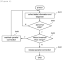
- FIG. 4 is an operation flowchart of a control method of the battery management apparatus according to an embodiment of the present invention.
- the control method illustrated in FIG. 4 may be performed in a battery management apparatus that manages and controls a battery connected in parallel with other batteries.
- the battery management apparatus may correspond to a battery management system (BMS) that directly manages a corresponding battery or may correspond to an upper BMS (e.g., a battery system controller (BSC), an energy management system (EMS), or a power management system (PMS)) of the BMS.
- BMS battery management system
- BSC battery system controller
- EMS energy management system
- PMS power management system
- the battery management apparatus may collect state information of the battery and diagnose whether the battery is abnormal based on the collected state information (S410). For example, the battery management apparatus collects state information including one or more of a voltage value, a current value, and a temperature value of the battery, and determines whether or not an abnormal state such as occurrence of a short circuit or ignition based on the collected state information.
- the battery management apparatus may determine whether the SOC of the battery is within a threshold SOC range predefined as an SOC estimation impossible section (S430). Here, the battery management apparatus may control whether to release the parallel connection according to whether the SOC of the battery is within a threshold SOC range.
- the threshold SOC range may be predefined as a section of SOC in which the voltage change relative to SOC change is equal to or less than a predefined threshold value, in a correlation curve depicting a relationship between the SOC and the voltage of the battery.
- the threshold SOC range may be defined as 5 or more and 95 or less, or 10 or more and 90 or less.
- the battery management apparatus may control an input/output switch of the battery to be in an open state to release the parallel connection between the battery and other batteries (S440).
- the battery management apparatus 200 may disconnect the abnormal battery from the battery system.
- the battery management apparatus may maintain the parallel connection with other batteries (S450).
- the battery management apparatus re-determines whether an abnormal state has occurred in the battery (S410, S420), and if the battery is out of the threshold SOC range (N in S430), the battery management apparatus may release the parallel connection with other batteries (S440).
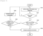
- FIG. 5 is an operation flowchart of a control method of the battery management apparatus according to another embodiment of the present invention.
- the control method shown in FIG. 5 is an embodiment in which a step of deciding a condition for maintaining a parallel connection is added to the control method shown in FIG. 4 .
- the battery management apparatus may collect state information of the battery and diagnose whether the battery is abnormal based on the collected state information (S510).
- the battery management apparatus may determine whether the SOC of the battery is within a threshold SOC range predefined as an SOC estimation impossible section (S530).
- the battery management apparatus may control an input/output switch of the battery to be in an open state to release the parallel connection with other batteries (S540).
- the battery management apparatus may determine whether a predefined condition for maintaining a parallel connection is satisfied (S550), wherein the condition for maintaining the parallel connection is predefined based on the state information of the battery, and may control whether to release the parallel connection depending the determination result.
- the battery management apparatus may release the parallel connection with other batteries (S540) if the condition for maintaining the parallel connection is not satisfied (N in S550), whereas the battery management apparatus may maintain the parallel connection (S560) if the condition for maintaining the parallel connection is satisfied (Y in S550).
- the condition for maintaining the parallel connection may include a first condition defined as a state in which a change amount in the cumulative current value of the battery is equal to or less than a predetermined threshold value.
- the battery management apparatus may check a cumulative current amount of the battery for a predetermined period.
- the change amount of cumulative current of the battery exceeds a predefined threshold (the first condition is not satisfied)
- the parallel connection with other batteries may be released, whereas when the change amount of cumulative current of the battery is less than the predefined threshold (the first condition is satisfied), the parallel connection with other batteries may be maintained.
- the parallel connection with other batteries may be released as the voltage changes due to the cumulative current (the first condition turning to be not satisfied) and the SOC estimation becomes possible afterwards.
- the condition for maintaining the parallel connection may include a second condition defined as a battery stable state.
- the second condition may be defined as a state in which a state value including at least one of a temperature value, a current value, and a voltage value of the battery is equal to or less than a predefined threshold value.
- the second condition may be defined as a state in which a change amount of a state value including at least one of a temperature value, a current value, and a voltage value of the battery is equal to or less than a predefined threshold value.
- the battery management apparatus may monitor a state value of the battery for a predetermined period of time. If the state value of the battery exceeds a predefined threshold (the second condition is not satisfied), the parallel connection with other batteries may be released, whereas if the state value of the battery is equal to or less than a predefined threshold (the second condition satisfied), the parallel connection with other batteries may be maintained.
- a predefined threshold the second condition is not satisfied
- the parallel connection with other batteries may be released if the battery is in an unstable state (e.g., a dangerous state in which the temperature value exceeds a threshold value) (the second condition is not satisfied).
- the battery management apparatus may maintain a parallel connection with other batteries if both the first and the second conditions, included in the condition for maintaining the parallel connection, are satisfied, whereas the battery management apparatus may release the parallel connection with other batteries if either one of the first and the second conditions is not satisfied.
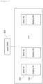
- FIG. 6 is a block diagram of a battery management apparatus according to embodiments of the present invention.
- the battery management apparatus 600 may correspond to an apparatus located in a battery system, which manages and controls a battery connected in parallel with other batteries.
- the battery control apparatus 600 may correspond to a rack battery management system (RBMS), a battery system controller (BSC), an energy management system (EMS), or a power management system (PMS), or may be implemented by being included in any one of them.
- RBMS rack battery management system
- BSC battery system controller
- EMS energy management system
- PMS power management system
- the battery management apparatus 600 may include at least one processor 610, a memory 620 that stores at least one instruction executed by the processor, and a transceiver 630 connected to a network to perform communication.
- the at least one instruction may include an instruction to diagnose whether or not the battery is abnormal based on the state information of the battery; and an instruction to, upon the battery determined to be in an abnormal state, control whether to release the parallel connection between the battery and the one or more other batteries based on whether a state of charge (SOC) of the battery is within a threshold SOC range which is predefined as SOC estimation impossible section.
- SOC state of charge
- the threshold SOC range may be predefined as a section of SOC in which the voltage change relative to SOC change is equal to or less than a predefined threshold value, in a correlation curve depicting a relationship between the SOC and the voltage of the battery.
- the instruction to control whether to release the parallel connection may include an instruction to release the parallel connection between the battery and the one or more other batteries when the SOC of the battery is out of the threshold SOC range.
- the instruction to control whether to release the parallel connection may include: an instruction to, upon the SOC of the battery being within the threshold SOC range, control whether to release the parallel connection between the battery and the one or more other batteries according to whether a condition for maintaining a parallel connection is satisfied, wherein the condition for maintaining a parallel connection is predefined based on the state information of the battery.
- the instruction to control whether to release the parallel connection include an instruction to maintain the parallel connection between the battery and the one or more other batteries in the instance that a first condition is satisfied, wherein the first condition is defined as a state in which a change amount of a cumulative current value of the battery is less than or equal to a predefined threshold value.
- the instruction to control whether to release the parallel connection include: an instruction to maintain the parallel connection between the battery and the one or more other batteries in the instance that a second condition is satisfied, wherein the second condition is defined as a state in which a state value including at least one of a temperature value, a current value, and a voltage value of the battery is equal to or less than a predefined threshold value, or defined as a state in which a change amount of the state value is equal to or less than a predefined threshold value.
- the instruction to control whether to release the parallel connection include an instruction to release the parallel connection between the battery and the one or more other batteries when the condition for maintaining a parallel connection is not satisfied.
- the battery management apparatus 600 may further include an input interface 640, an output interface 650, a storage device 660, and the like. Respective components included in the battery control apparatus 600 may be connected by a bus 670 to management with each other.
- the processor 610 may mean a central processing unit (CPU), a graphics processing unit (GPU), or a dedicated processor on which methods according to embodiments of the present invention are performed.
- the memory (or storage device) may include at least one of a volatile storage medium and a nonvolatile storage medium.
- the memory may include at least one of read only memory (ROM) and random access memory (RAM).
- the operations of the method according to the embodiments of the present invention may be implemented as a computer-readable program or code on a computer-readable recording medium.
- the computer-readable recording medium includes all types of recording devices in which data readable by a computer system is stored.
- the computer-readable recording medium may be distributed in a network-connected computer system to store and execute computer-readable programs or codes in a distributed manner.
- a block or apparatus corresponds to a method step or feature of a method step.
- aspects described in the context of a method may also represent a feature of a corresponding block or item or a corresponding apparatus.
- Some or all of the method steps may be performed by (or using) a hardware device, such as, for example, a microprocessor, a programmable computer, or an electronic circuit. In some embodiments, one or more of the most important method steps may be performed by such an apparatus.
Landscapes
- Engineering & Computer Science (AREA)
- Chemical & Material Sciences (AREA)
- Chemical Kinetics & Catalysis (AREA)
- Electrochemistry (AREA)
- General Chemical & Material Sciences (AREA)
- Power Engineering (AREA)
- Manufacturing & Machinery (AREA)
- Microelectronics & Electronic Packaging (AREA)
- Crystallography & Structural Chemistry (AREA)
- Inorganic Chemistry (AREA)
- Charge And Discharge Circuits For Batteries Or The Like (AREA)
- Secondary Cells (AREA)
Abstract
Description
- This application claims priority to and the benefit of
Korean Patent Application No.10-2022-0122260 filed in the Korean Intellectual Property Office on September 27, 2022 Korean Patent Application No.10-2023-0006698 filed in the Korean Intellectual Property Office on January 17, 2023 - The present invention relates to a battery management apparatus and an operating method thereof, and more particularly, to a battery management apparatus for a stable operation of a battery system including a battery having a voltage plateau and an operating method thereof.
- A secondary battery is a battery that can be recharged and reused even after being discharged. The secondary battery can be used as an energy source for small devices such as mobile phones, tablet PCs and vacuum cleaners, and also used as an energy source for medium and large devices such as an energy storage system (ESS) for automobiles and smart grids.
- The secondary battery is applied to a system in a form of an assembly such as a battery module in which a plurality of battery cells are connected in series and parallel or a battery pack in which battery modules are connected in series and parallel according to system requirements.
- Carbon materials are mainly used as an anode active material of lithium secondary batteries whereas lithium-containing cobalt oxide (LiCoO2) is mainly used as a cathode active material, and lithium-containing manganese oxides (LiMnO2 LiMn2O4, etc.) and lithium-containing nickel oxide (LiNiO2) are also being considered.
- Recently, a lithium iron phosphate (LiFePO4)-based compound has been used as a cathode active material for a lithium secondary battery. A lithium iron phosphate (LFP) battery using lithium iron phosphate as a cathode active material is superior in terms of thermal stability and cost efficiency compared to other types of batteries. However, the LFP battery exhibits a plateau characteristic with a voltage plateau section in a charging characteristic curve (correlation curve between open circuit voltage and SOC) and a problem arises that the state of charge (SOC) cannot be accurately estimated in the plateau section.
- During operation of a battery system including battery assemblies connected in parallel, if an abnormality occurs in a specific battery assembly, the battery assembly is disconnected from the battery system (parallel connection released) and can be reconnected to the battery system when the abnormality is resolved. Here, the corresponding battery assembly can be reconnected to the battery system if the SOC of the corresponding battery assembly is the same as or very similar to those of other battery assemblies.
- However, in the case of a battery system to which an LFP battery is applied, if an abnormality occurs in a specific battery assembly in the voltage plateau section, the battery assembly needs to be fully charged or fully discharged in order to be reconnected to the battery system after the battery assembly is disconnected from the battery system. This is because the SOC of the LFP battery cannot be accurately estimated in the voltage plateau section. Accordingly, a problem arises in that a considerable amount of time is required until the corresponding battery assembly is reconnected to the battery system.
- To obviate one or more problems of the related art, embodiments of the present disclosure provide a battery management apparatus for a stable operation of a battery system including a battery having a voltage plateau.
- To obviate one or more problems of the related art, embodiments of the present disclosure also provide a control method of the battery management apparatus.
- To obviate one or more problems of the related art, embodiments of the present disclosure also provide a battery system including the battery management apparatus.
- In order to achieve the objective of the present disclosure, a battery management apparatus for managing and controlling a battery which is connected in parallel with one or more other batteries may include at least one processor; and a memory configured to store at least one instruction executed by the at least one processor.
- Here, the at least one instruction include an instruction to diagnose whether or not the battery is abnormal based on the state information of the battery; and an instruction to, upon the battery determined to be in an abnormal state, control whether to release the parallel connection between the battery and the one or more other batteries based on whether a state of charge (SOC) of the battery is within a threshold SOC range which is predefined as SOC estimation impossible section.
- Here, the threshold SOC range may be predefined as a section of SOC in which the voltage change relative to SOC change is equal to or less than a predefined threshold value, in a correlation curve depicting a relationship between the SOC and the voltage of the battery.
- The instruction to control whether to release the parallel connection may include an instruction to release the parallel connection between the battery and the one or more other batteries when the SOC of the battery is out of the threshold SOC range.
- The instruction to control whether to release the parallel connection may include an instruction to, upon the SOC of the battery being within the threshold SOC range, control whether to release the parallel connection between the battery and the one or more other batteries according to whether a condition for maintaining the parallel connection is satisfied, wherein the condition for maintaining the parallel connection is predefined based on the state information of the battery.
- The instruction to control whether to release the parallel connection may include an instruction to maintain the parallel connection between the battery and the one or more other batteries in the instance that a first condition is satisfied, wherein the first condition is defined as a state in which a change amount of a cumulative current value of the battery is less than or equal to a predefined threshold value.
- The instruction to control whether to release the parallel connection may include an instruction to maintain the parallel connection between the battery and the one or more other batteries in the instance that a second condition is satisfied, wherein the second condition is defined as a state in which a state value including at least one of a temperature value, a current value, and a voltage value of the battery is equal to or less than a predefined threshold value, or defined as a state in which a change amount of the state value is equal to or less than a predefined threshold value.
- The instruction to control whether to release the parallel connection may include an instruction to release the parallel connection between the battery and the one or more other batteries when the condition for maintaining the parallel connection is not satisfied.
- According to another embodiment of the present disclosure, a control method, performed by a battery control apparatus that manages and controls a battery which is connected in parallel with one or more other batteries, may include diagnosing whether or not the battery is abnormal based on the state information of the battery; and upon the battery determined to be in an abnormal state, controlling whether to release the parallel connection between the battery and the one or more other batteries based on whether a state of charge (SOC) of the battery is within a threshold SOC range which is predefined as SOC estimation impossible section.
- Here, the threshold SOC range may be predefined as a section of SOC in which the voltage change relative to SOC change is equal to or less than a predefined threshold value, in a correlation curve depicting a relationship between the SOC and the voltage of the battery.
- The controlling whether to release the parallel connection may include releasing the parallel connection between the battery and the one or more other batteries when the SOC of the battery is out of the threshold SOC range.
- The controlling whether to release the parallel connection may include, upon the SOC of the battery being within the threshold SOC range, controlling whether to release the parallel connection between the battery and the one or more other batteries according to whether a condition for maintaining a parallel connection is satisfied, wherein the condition for maintaining a parallel connection is predefined based on the state information of the battery.
- The controlling whether to release the parallel connection may include maintaining the parallel connection between the battery and the one or more other batteries in the instance that a first condition is satisfied, wherein the first condition is defined as a state in which a change amount of a cumulative current value of the battery is less than or equal to a predefined threshold value.
- The controlling whether to release the parallel connection may include maintaining the parallel connection between the battery and the one or more other batteries in the instance that a second condition is satisfied, wherein the second condition is defined as a state in which a state value including at least one of a temperature value, a current value, and a voltage value of the battery is equal to or less than a predefined threshold value, or defined as a state in which a change amount of the state value is equal to or less than a predefined threshold value.
- The controlling whether to release the parallel connection may include releasing the parallel connection between the battery and the one or more other batteries when the condition for maintaining the parallel connection is not satisfied.
- According to another embodiment of the present disclosure, a battery system may include a plurality of batteries connected in parallel; and a plurality of battery management apparatus provided in correspondence to the plurality of batteries, respectively and configured to manage and control respective corresponding batteries. Here, the battery management apparatus may be configured to diagnose whether or not the battery is abnormal based on the state information of the battery and upon the battery determined to be in an abnormal state, to control whether to release the parallel connection between the battery and the one or more other batteries based on whether a state of charge (SOC) of the battery is within a threshold SOC range which is predefined as SOC estimation impossible section.
- Here, the threshold SOC range may be predefined as a section of SOC in which the voltage change relative to SOC change is equal to or less than a predefined threshold value, in a correlation curve depicting a relationship between the SOC and the voltage of the battery.
- The battery management apparatus is further configured to release the parallel connection between the battery and the one or more other batteries when the SOC of the battery is out of the threshold SOC range.
- The battery management apparatus may further be configured to, upon the SOC of the battery being within the threshold SOC range, control whether to release the parallel connection between the battery and the one or more other batteries according to whether a condition for maintaining a parallel connection is satisfied, wherein the condition for maintaining a parallel connection is predefined based on the state information of the battery.
- The battery management apparatus may further be configured to maintain the parallel connection between the battery and the one or more other batteries in the instance that a first condition is satisfied, wherein the first condition is defined as a state in which a change amount of a cumulative current value of the battery is less than or equal to a predefined threshold value.
- The battery management apparatus may further be configured to maintain the parallel connection between the battery and the one or more other batteries in the instance that a second condition is satisfied, wherein the second condition is defined as a state in which a state value including at least one of a temperature value, a current value, and a voltage value of the battery is equal to or less than a predefined threshold value, or defined as a state in which a change amount of the state value is equal to or less than a predefined threshold value.
- The battery management apparatus may further be configured to release the parallel connection between the battery and the one or more other batteries when the condition for maintaining a parallel connection is not satisfied.
- According to embodiments of the present disclosure, operational stability of the battery system can be improved by minimizing disconnection of an abnormal battery in the voltage plateau section.
-
-
FIG. 1 is a block diagram of a general energy storage system. -
FIG. 2 shows a charging characteristic curve of the LFP battery. -
FIG. 3 is a block diagram of a battery system according to embodiments of the present invention. -
FIG. 4 is an operation flowchart of a control method of the battery management apparatus according to an embodiment of the present invention. -
FIG. 5 is an operation flowchart of a control method of the battery management apparatus according to another embodiment of the present invention. -
FIG. 6 is a block diagram of a battery management apparatus according to embodiments of the present invention. - 100: battery
- 200: battery management apparatus
- 300: upper battery management apparatus
- 600: battery management apparatus
- The present invention may be modified in various forms and have various embodiments, and specific embodiments thereof are shown by way of example in the drawings and will be described in detail below. It should be understood, however, that there is no intent to limit the present invention to the specific embodiments, but on the contrary, the present invention is to cover all modifications, equivalents, and alternatives falling within the spirit and technical scope of the present invention. Like reference numerals refer to like elements throughout the description of the figures.
- It will be understood that, although the terms such as first, second, A, B, and the like may be used herein to describe various elements, these elements should not be limited by these terms. These terms are only used to distinguish one element from another. For example, a first element could be termed a second element, and, similarly, a second element could be termed a first element, without departing from the scope of the present invention. As used herein, the term "and/or" includes combinations of a plurality of associated listed items or any of the plurality of associated listed items.
- It will be understood that when an element is referred to as being "coupled" or "connected" to another element, it can be directly coupled or connected to the other element or an intervening element may be present. In contrast, when an element is referred to as being "directly coupled" or "directly connected" to another element, there is no intervening element present.
- The terms used herein is for the purpose of describing specific embodiments only and are not intended to limit the present invention. As used herein, the singular forms "a", "an" and "the" are intended to include the plural forms as well, unless the context clearly indicates otherwise. It will be further understood that the terms "comprises", "comprising", "includes", "including" and/or "having", when used herein, specify the presence of stated features, integers, steps, operations, constitutional elements, components and/or combinations thereof, but do not preclude the presence or addition of one or more other features, integers, steps, operations, constitutional elements, components, and/or combinations thereof.
- Unless otherwise defined, all terms used herein, including technical and scientific terms, have the same meanings as commonly understood by one skilled in the art to which the present invention belongs. It will be further understood that terms, such as those defined in commonly used dictionaries, should be interpreted as having meanings that are consistent with their meanings in the context of the relevant art and will not be interpreted in an idealized or overly formal sense unless expressly so defined herein.
- Some terms used herein are defined as follows.
- A battery cell is a minimum unit that serves to store power and a battery module refers to an assembly in which a plurality of battery cells are electrically connected.
- A battery rack refers to a system of a minimum single structure which is assembled by electrically connecting module units, set by a battery manufacturer, and can be monitored and controlled by a battery management apparatus/system (BMS). A battery rack may include several battery modules and a battery protection unit or any other protection device.
- A battery bank refers to a group of large-scale battery rack systems configured by connecting several racks in parallel. A bank BMS for a battery bank may monitor and control rack BMSs, each of which manages a battery rack.
- A battery assembly may include a plurality of electrically connected battery cells, and refers to an assembly that functions as a power supply source by being applied to a specific system or device. Here, the battery assembly may mean a battery module, a battery pack, a battery rack, or a battery bank, but the scope of the present invention is not limited to these entities.
- A battery system controller (BSC) is a top-level control device that controls a battery system including a battery bank or a battery system with a multiple bank level structure.
- State of charge (SOC) refers to a current state of charge of a battery, represented in percent points [%], and State of Health (SOH) may be a current condition of a battery compared to its ideal or original conditions, represented in percent points [%].
-
FIG. 1 is a block diagram of a general energy storage system. - In an energy storage system (ESS), typically a battery cell is a minimum unit of storing energy or power. A series/parallel combination of battery cells may form a battery module, and a plurality of battery packs may form a battery rack. In other words, a battery rack can be a minimum unit of a battery system as a series/parallel combination of battery packs. Here, depending on a device or a system in which the battery is used, a battery pack may be referred to as a battery module.
- Referring to
FIG. 1 , abattery rack 10 may include a plurality of battery modules and a battery protection unit (BPU) or any other protection device. The battery rack can be monitored and controlled through a rack BMS(RBMS). The RBMS may monitor a current, a voltage and a temperature, among others, of each battery rack to be managed, calculate a state of charge (SOC) of the battery based on monitoring results, and control charging and discharging of the battery rack. - The battery protection unit (BPU) is a device for protecting the battery rack from an abnormal current and a fault current in the battery rack. The BPU may include a main contactor (MC), a fuse, and a circuit breaker (CB) or a disconnect switch (DS). The BPU may control a battery system rack by rack through on/off controlling the main contactor (MC) based on a control from the Rack BMS. The BPU may also protect the battery rack from a short circuit current using a fuse in the event of a short circuit. As such, the battery system can be controlled through a protection device such as a BPU or a switchgear.
- A battery system controller (BSC) 20 is located in each battery section which includes a plurality of batteries, peripheral circuits, and devices to monitor and control objects such as a voltage, a current, a temperature, and a circuit breaker. The battery system controller is an uppermost control apparatus in a bank level battery system including a plurality of battery racks. The battery system controller may also be used as a control apparatus in a battery system having a plurality of bank level structures.
- Furthermore, a power conversion system (PCS) 40 installed in each battery section performs charging/discharging based on a charge/discharge command (e.g., a charge or discharge command) from the energy management system (EMS) 30. The power conversion system (PCS) 40 may include a power conversion unit (DC/AC inverter) and a controller. The output of each BPU may be connected to the
PCS 40 through a DC bus, and thePCS 40 may be connected to a power grid. In addition, the EMS(or Power Management System (PMS)) 30 may manage the overall energy storage system (ESS). -
FIG. 2 shows a charging characteristic curve of an LFP battery. - More specifically,
FIG. 2 shows a charging characteristic curve of a lithium iron phosphate (LFP) battery using lithium iron phosphate as a cathode active material. The charging characteristic curve represents a correspondence between an open circuit voltage (OCV) and a SOC measured during a battery charging process. - During operation of a battery system, a battery management apparatus may perform balancing control based on SOCs of batteries or reconnecting at least one battery disconnected from the battery system. Here, a method of measuring an open-circuit voltage value of the battery and estimating the SOC of the battery based on the measured open-circuit voltage value is mainly used, in order to calculate the SOC of a battery.
- Referring to
FIG. 2 , the charging characteristic curve of the LFP battery has a voltage plateau in the SOC range of about 10% to about 90%. In the case of an LFP battery having such a plateau characteristic, it is difficult to accurately estimate the SOC in the plateau section, accurate estimation is possible only in a non- plateau section (e.g., a section where the SOC is 90% or more, or a section where the SOC is 10% or less). In other words, in a battery system to which the LFP battery is applied, accurate SOC estimation is possible only in a very limited SOC section. - In
FIG. 1 , if an abnormality occurs in a specific battery rack among a plurality ofbattery racks 10 included in a battery system, a parallel connection between the corresponding battery rack and other battery racks may released and the corresponding battery rack may be disconnected from the battery system. When the abnormal state of the corresponding battery rack is resolved by inspection, the battery rack may be reconnected to the battery system. Here, the corresponding battery rack needs to be reconnected to the battery system when the SOCs of the corresponding battery rack and other battery racks are very similar, for stable operation of the battery system. - Here, in the case of battery racks with LFP batteries, battery racks need to be fully charged or fully discharged because accurate estimation of SOC is possible only in non-flat sections (e.g., a section with SOC of 90% or more, or a section with SOC of 10% or less). Thus, it takes a considerable amount of time to reconnect the disconnected battery rack to the battery system.
- The present invention is presented to solve this problem and relates to a battery control apparatus and a control method thereof, which minimizes disconnection of an abnormal battery in an exact SOC estimation impossible section thereby stably operating the battery system.
- Hereinafter, preferred embodiments according to the present invention will be described in detail with reference to the accompanying drawings.
-
FIG. 3 is a block diagram of a battery system according to embodiments of the present invention. - Referring to
FIG. 3 , the battery system according to embodiments of the present invention includes a plurality ofbatteries 100 and a plurality of battery management systems/apparatuses (BMSs) 200 provided in correspondence to the plurality of batteries, respectively, and for managing and controlling corresponding batteries. The plurality ofbatteries 100 may be electrically connected to each other in parallel. - In the present disclosure, the
battery 100 may mean a battery assembly. In other words, thebattery 100 according to the present invention may correspond to a battery module, a battery pack, a battery rack, or a battery bank. - In embodiments, the
battery 100 may correspond to a battery assembly including one or more battery cells (e.g., LFP battery cells) having at least a portion of a voltage plateau section in a charging characteristic curve. - The
BMS 200 may manage and control itscorresponding battery 100 by collecting state information on thecorresponding battery 100 and performing a predefined control operation based on the collected state information. Here, theBMS 200 may control charging and discharging of the battery based on the state information of the battery and diagnose whether the battery cells are out of order. - The
battery management apparatus 200 may control a switching device provided at an input/output terminal of thebattery 100 to release or reconnect the parallel connection with other batteries. - Each of the plurality of
BMSs 200 may be connected to an upperbattery management apparatus 300 through a network, transmit battery state information of the battery to the upperbattery management apparatus 300, receive control commands from the upperbattery management apparatus 300, and operate based on the received control commands. Here, the upperbattery management apparatus 300 may correspond to a battery system controller (BSC), an energy management system (EMS), or a power management system (PMS). - Each of the
battery management apparatuses 200 may diagnose whether or not each battery has an abnormality based on state information of a corresponding battery. For example, thebattery management apparatus 200 may detect a failure occurrence such as a short circuit or ignition, based on state information including at least one of a voltage value, a current value, and a temperature value of the battery. - When an abnormal state occurs in a specific battery, the
battery management apparatus 200 corresponding to the abnormal battery may determine whether the SOC of the corresponding battery is within a threshold SOC range predefined as an SOC estimation impossible section. Here, thebattery management apparatus 200 may check a voltage value of the battery at the time of detecting the abnormal state of the battery, obtain the SOC corresponding to the checked voltage value through a pre-stored voltage-SOC correlation table, and determine the current SOC of the battery. - The threshold SOC range may be predefined as a section of SOC in which the voltage change relative to SOC change is equal to or less than a predefined threshold value, in a correlation curve depicting a relationship between the SOC and the voltage of the battery. For example, the threshold SOC range may be defined as 5 or more and 95 or less, or 10 or more and 90 or less.
- Thereafter, the
battery management apparatus 200 may control whether to release the parallel connection between the abnormal battery and other batteries based on whether the SOC of the abnormal battery is within the threshold SOC range. - When the SOC of the abnormal battery is out of a predefined threshold SOC range, the
battery management apparatus 200 may controls an input/output switch of the corresponding battery to be in an open state to release the parallel connection with other batteries. In other words, when the abnormal battery is in an SOC estimation possible state, thebattery management apparatus 200 may disconnect the abnormal battery from the battery system, and control to reconnect the corresponding battery to the battery system based on the calculated SOC when the abnormal state of the battery is resolved. - When the SOC of the abnormal battery is within the predefined threshold SOC range, the
battery management apparatus 200 may maintain the parallel connection between the corresponding battery and other batteries. Here, thebattery management apparatus 200 may release the parallel connection with other batteries when the corresponding battery becomes out of the threshold SOC range. In other words, when the abnormal battery is in an SOC estimation impossible state, thebattery management apparatus 200 may not immediately disconnect the abnormal battery from the battery system, but disconnect the abnormal battery from the battery system when the abnormal battery becomes an SOC estimation possible state. Accordingly, unnecessary time consumed until the abnormal battery is reconnected to the battery system may be reduced. -
FIG. 4 is an operation flowchart of a control method of the battery management apparatus according to an embodiment of the present invention. - The control method illustrated in
FIG. 4 may be performed in a battery management apparatus that manages and controls a battery connected in parallel with other batteries. Here, the battery management apparatus may correspond to a battery management system (BMS) that directly manages a corresponding battery or may correspond to an upper BMS (e.g., a battery system controller (BSC), an energy management system (EMS), or a power management system (PMS)) of the BMS. - The battery management apparatus may collect state information of the battery and diagnose whether the battery is abnormal based on the collected state information (S410). For example, the battery management apparatus collects state information including one or more of a voltage value, a current value, and a temperature value of the battery, and determines whether or not an abnormal state such as occurrence of a short circuit or ignition based on the collected state information.
- When an abnormal state occurs in the battery (Y in S420), the battery management apparatus may determine whether the SOC of the battery is within a threshold SOC range predefined as an SOC estimation impossible section (S430). Here, the battery management apparatus may control whether to release the parallel connection according to whether the SOC of the battery is within a threshold SOC range.
- The threshold SOC range may be predefined as a section of SOC in which the voltage change relative to SOC change is equal to or less than a predefined threshold value, in a correlation curve depicting a relationship between the SOC and the voltage of the battery. For example, the threshold SOC range may be defined as 5 or more and 95 or less, or 10 or more and 90 or less.
- When the SOC of the battery is out of the predetermined threshold SOC range (N in S430), the battery management apparatus may control an input/output switch of the battery to be in an open state to release the parallel connection between the battery and other batteries (S440). In other words, when the abnormal battery is in an SOC estimation possible state, the
battery management apparatus 200 may disconnect the abnormal battery from the battery system. - When the SOC of the battery is within a predetermined threshold SOC range (Y in S430), the battery management apparatus may maintain the parallel connection with other batteries (S450).
- Thereafter, the battery management apparatus re-determines whether an abnormal state has occurred in the battery (S410, S420), and if the battery is out of the threshold SOC range (N in S430), the battery management apparatus may release the parallel connection with other batteries (S440).
-
FIG. 5 is an operation flowchart of a control method of the battery management apparatus according to another embodiment of the present invention. The control method shown inFIG. 5 is an embodiment in which a step of deciding a condition for maintaining a parallel connection is added to the control method shown inFIG. 4 . - The battery management apparatus may collect state information of the battery and diagnose whether the battery is abnormal based on the collected state information (S510).
- When an abnormal state occurs in the battery (Y in S520), the battery management apparatus may determine whether the SOC of the battery is within a threshold SOC range predefined as an SOC estimation impossible section (S530).
- When the SOC of the battery is out of the predetermined threshold SOC range (N in S530), the battery management apparatus may control an input/output switch of the battery to be in an open state to release the parallel connection with other batteries (S540).
- When the SOC of the battery is within the predefined threshold SOC range (Y in S530), the battery management apparatus may determine whether a predefined condition for maintaining a parallel connection is satisfied (S550), wherein the condition for maintaining the parallel connection is predefined based on the state information of the battery, and may control whether to release the parallel connection depending the determination result. Here, the battery management apparatus may release the parallel connection with other batteries (S540) if the condition for maintaining the parallel connection is not satisfied (N in S550), whereas the battery management apparatus may maintain the parallel connection (S560) if the condition for maintaining the parallel connection is satisfied (Y in S550).
- The condition for maintaining the parallel connection may include a first condition defined as a state in which a change amount in the cumulative current value of the battery is equal to or less than a predetermined threshold value.
- More specifically, when the abnormal battery is within the threshold SOC range (SOC estimation impossible state), the battery management apparatus may check a cumulative current amount of the battery for a predetermined period. When the change amount of cumulative current of the battery exceeds a predefined threshold (the first condition is not satisfied), the parallel connection with other batteries may be released, whereas when the change amount of cumulative current of the battery is less than the predefined threshold (the first condition is satisfied), the parallel connection with other batteries may be maintained.
- In other words, even if the battery is in an SOC estimation impossible state (a state within the threshold SOC range) at a time of determining whether an abnormality occurs, the parallel connection with other batteries may be released as the voltage changes due to the cumulative current (the first condition turning to be not satisfied) and the SOC estimation becomes possible afterwards.
- The condition for maintaining the parallel connection may include a second condition defined as a battery stable state. In an embodiment, the second condition may be defined as a state in which a state value including at least one of a temperature value, a current value, and a voltage value of the battery is equal to or less than a predefined threshold value. In another embodiment, the second condition may be defined as a state in which a change amount of a state value including at least one of a temperature value, a current value, and a voltage value of the battery is equal to or less than a predefined threshold value.
- More specifically, when the abnormal battery is in a state within a threshold SOC range (SOC estimation impossible state), the battery management apparatus may monitor a state value of the battery for a predetermined period of time. If the state value of the battery exceeds a predefined threshold (the second condition is not satisfied), the parallel connection with other batteries may be released, whereas if the state value of the battery is equal to or less than a predefined threshold (the second condition satisfied), the parallel connection with other batteries may be maintained.
- In other words, even if the battery is in an SOC estimation impossible state (a state within the threshold SOC range) at a time of determining whether an abnormality occurs, the parallel connection with other batteries may be released if the battery is in an unstable state (e.g., a dangerous state in which the temperature value exceeds a threshold value) (the second condition is not satisfied).
- In embodiments, the battery management apparatus may maintain a parallel connection with other batteries if both the first and the second conditions, included in the condition for maintaining the parallel connection, are satisfied, whereas the battery management apparatus may release the parallel connection with other batteries if either one of the first and the second conditions is not satisfied.
-
FIG. 6 is a block diagram of a battery management apparatus according to embodiments of the present invention. - The
battery management apparatus 600 according to embodiments of the present invention may correspond to an apparatus located in a battery system, which manages and controls a battery connected in parallel with other batteries. For example, thebattery control apparatus 600 may correspond to a rack battery management system (RBMS), a battery system controller (BSC), an energy management system (EMS), or a power management system (PMS), or may be implemented by being included in any one of them. - The
battery management apparatus 600 may include at least oneprocessor 610, amemory 620 that stores at least one instruction executed by the processor, and atransceiver 630 connected to a network to perform communication. - The at least one instruction may include an instruction to diagnose whether or not the battery is abnormal based on the state information of the battery; and an instruction to, upon the battery determined to be in an abnormal state, control whether to release the parallel connection between the battery and the one or more other batteries based on whether a state of charge (SOC) of the battery is within a threshold SOC range which is predefined as SOC estimation impossible section.
- Here, the threshold SOC range may be predefined as a section of SOC in which the voltage change relative to SOC change is equal to or less than a predefined threshold value, in a correlation curve depicting a relationship between the SOC and the voltage of the battery.
- The instruction to control whether to release the parallel connection may include an instruction to release the parallel connection between the battery and the one or more other batteries when the SOC of the battery is out of the threshold SOC range.
- The instruction to control whether to release the parallel connection may include: an instruction to, upon the SOC of the battery being within the threshold SOC range, control whether to release the parallel connection between the battery and the one or more other batteries according to whether a condition for maintaining a parallel connection is satisfied, wherein the condition for maintaining a parallel connection is predefined based on the state information of the battery.
- The instruction to control whether to release the parallel connection include an instruction to maintain the parallel connection between the battery and the one or more other batteries in the instance that a first condition is satisfied, wherein the first condition is defined as a state in which a change amount of a cumulative current value of the battery is less than or equal to a predefined threshold value.
- The instruction to control whether to release the parallel connection include: an instruction to maintain the parallel connection between the battery and the one or more other batteries in the instance that a second condition is satisfied, wherein the second condition is defined as a state in which a state value including at least one of a temperature value, a current value, and a voltage value of the battery is equal to or less than a predefined threshold value, or defined as a state in which a change amount of the state value is equal to or less than a predefined threshold value.
- The instruction to control whether to release the parallel connection include an instruction to release the parallel connection between the battery and the one or more other batteries when the condition for maintaining a parallel connection is not satisfied.
- The
battery management apparatus 600 may further include aninput interface 640, anoutput interface 650, astorage device 660, and the like. Respective components included in thebattery control apparatus 600 may be connected by abus 670 to management with each other. - Here, the
processor 610 may mean a central processing unit (CPU), a graphics processing unit (GPU), or a dedicated processor on which methods according to embodiments of the present invention are performed. The memory (or storage device) may include at least one of a volatile storage medium and a nonvolatile storage medium. For example, the memory may include at least one of read only memory (ROM) and random access memory (RAM). - The operations of the method according to the embodiments of the present invention may be implemented as a computer-readable program or code on a computer-readable recording medium. The computer-readable recording medium includes all types of recording devices in which data readable by a computer system is stored. In addition, the computer-readable recording medium may be distributed in a network-connected computer system to store and execute computer-readable programs or codes in a distributed manner.
- Although some aspects of the invention have been described in the context of the apparatus, it may also represent a description according to a corresponding method, wherein a block or apparatus corresponds to a method step or feature of a method step. Similarly, aspects described in the context of a method may also represent a feature of a corresponding block or item or a corresponding apparatus. Some or all of the method steps may be performed by (or using) a hardware device, such as, for example, a microprocessor, a programmable computer, or an electronic circuit. In some embodiments, one or more of the most important method steps may be performed by such an apparatus.
- In the forgoing, the present invention has been described with reference to the exemplary embodiment of the present invention, but those skilled in the art may appreciate that the present invention may be variously corrected and changed within the range without departing from the spirit and the area of the present invention described in the appending claims.
Claims (21)
- A battery management apparatus for managing and controlling a battery which is connected in parallel with one or more other batteries, the apparatus comprising:at least one processor; anda memory configured to store at least one instruction executed by the at least one processor,wherein the at least one instruction includes:an instruction to diagnose whether or not the battery is abnormal based on the state information of the battery; andan instruction to, upon the battery determined to be in an abnormal state, control whether to release the parallel connection between the battery and the one or more other batteries based on whether a state of charge (SOC) of the battery is within a threshold SOC range which is predefined as SOC estimation impossible section.
- The battery management apparatus of claim 1, wherein the threshold SOC range is predefined as a section of SOC in which the voltage change relative to SOC change is equal to or less than a predefined threshold value, in a correlation curve depicting a relationship between the SOC and the voltage of the battery.
- The battery management apparatus of claim 1, wherein the instruction to control whether to release the parallel connection includes:
an instruction to release the parallel connection between the battery and the one or more other batteries when the SOC of the battery is out of the threshold SOC range. - The battery management apparatus of claim 1, wherein the instruction to control whether to release the parallel connection includes:
an instruction to, upon the SOC of the battery being within the threshold SOC range, control whether to release the parallel connection between the battery and the one or more other batteries according to whether a condition for maintaining a parallel connection is satisfied, wherein the condition for maintaining a parallel connection is predefined based on the state information of the battery. - The battery management apparatus of claim 4, wherein the instruction to control whether to release the parallel connection includes:
an instruction to maintain the parallel connection between the battery and the one or more other batteries in the instance that a first condition is satisfied, wherein the first condition is defined as a state in which a change amount of a cumulative current value of the battery is less than or equal to a predefined threshold value. - The battery management apparatus of claim 4, wherein the instruction to control whether to release the parallel connection includes:
an instruction to maintain the parallel connection between the battery and the one or more other batteries in the instance that a second condition is satisfied, wherein the second condition is defined as a state in which a state value including at least one of a temperature value, a current value, and a voltage value of the battery is equal to or less than a predefined threshold value, or defined as a state in which a change amount of the state value is equal to or less than a predefined threshold value. - The battery management apparatus of claim 4, wherein the instruction to control whether to release the parallel connection includes:
an instruction to release the parallel connection between the battery and the one or more other batteries when the condition for maintaining a parallel connection is not satisfied. - A control method performed by a battery control apparatus that manages and controls a battery which is connected in parallel with one or more other batteries, the method comprising:diagnosing whether or not the battery is abnormal based on the state information of the battery; andupon the battery determined to be in an abnormal state, controlling whether to release the parallel connection between the battery and the one or more other batteries based on whether a state of charge (SOC) of the battery is within a threshold SOC range which is predefined as SOC estimation impossible section.
- The method of claim 8, wherein the threshold SOC range is predefined as a section of SOC, in which the voltage change relative to SOC change is equal to or less than a predefined threshold value, in a correlation curve depicting a relationship between the SOC and the voltage of the battery.
- The method of claim 8, wherein the controlling whether to release the parallel connection includes releasing the parallel connection between the battery and the one or more other batteries when the SOC of the battery is out of the threshold SOC range.
- The method of claim 8, wherein the controlling whether to release the parallel connection includes:
upon the SOC of the battery being within the threshold SOC range, controlling whether to release the parallel connection between the battery and the one or more other batteries according to whether a condition for maintaining a parallel connection is satisfied, wherein the condition for maintaining a parallel connection is predefined based on the state information of the battery. - The method of claim 11, wherein the controlling whether to release the parallel connection includes:
maintaining the parallel connection between the battery and the one or more other batteries in the instance that a first condition is satisfied, wherein the first condition is defined as a state in which a change amount of a cumulative current value of the battery is less than or equal to a predefined threshold value. - The method of claim 11, wherein the controlling whether to release the parallel connection includes:
maintaining the parallel connection between the battery and the one or more other batteries in the instance that a second condition is satisfied, wherein the second condition is defined as a state in which a state value including at least one of a temperature value, a current value, and a voltage value of the battery is equal to or less than a predefined threshold value, or defined as a state in which a change amount of the state value is equal to or less than a predefined threshold value. - The method of claim 11, wherein the controlling whether to release the parallel connection includes:
releasing the parallel connection between the battery and the one or more other batteries when the condition for maintaining a parallel connection is not satisfied. - A battery system comprising:a plurality of batteries connected in parallel; anda plurality of battery management apparatus provided in correspondence to the plurality of batteries, respectively and configured to manage and control respective corresponding batteries,wherein the battery management apparatus is configured to diagnose whether or not the battery is abnormal based on the state information of the battery and upon the battery determined to be in an abnormal state, to control whether to release the parallel connection between the battery and the one or more other batteries based on whether a state of charge (SOC) of the battery is within a threshold SOC range which is predefined as SOC estimation impossible section.
- The battery system of claim 15, wherein the threshold SOC range is predefined as a section of SOC, in which the voltage change relative to SOC change is equal to or less than a predefined threshold value, in a correlation curve depicting a relationship between the SOC and the voltage of the battery.
- The battery system of claim 15, wherein the battery management apparatus is further configured to release the parallel connection between the battery and the one or more other batteries when the SOC of the battery is out of the threshold SOC range.
- The battery system of claim 15, wherein the battery management apparatus is further configured to, upon the SOC of the battery being within the threshold SOC range, control whether to release the parallel connection between the battery and the one or more other batteries according to whether a condition for maintaining a parallel connection is satisfied, wherein the condition for maintaining a parallel connection is predefined based on the state information of the battery.
- The battery system of claim 18, wherein the battery management apparatus is further configured to maintain the parallel connection between the battery and the one or more other batteries in the instance that a first condition is satisfied, wherein the first condition is defined as a state in which a change amount of a cumulative current value of the battery is less than or equal to a predefined threshold value.
- The battery system of claim 18, wherein the battery management apparatus is further configured to maintain the parallel connection between the battery and the one or more other batteries in the instance that a second condition is satisfied, wherein the second condition is defined as a state in which a state value including at least one of a temperature value, a current value, and a voltage value of the battery is equal to or less than a predefined threshold value, or defined as a state in which a change amount of the state value is equal to or less than a predefined threshold value.
- The battery system of claim 18, wherein the battery management apparatus is further configured to release the parallel connection between the battery and the one or more other batteries when the condition for maintaining a parallel connection is not satisfied.
Applications Claiming Priority (3)
| Application Number | Priority Date | Filing Date | Title |
|---|---|---|---|
| KR20220122260 | 2022-09-27 | ||
| KR1020230006698A KR102658099B1 (en) | 2022-09-27 | 2023-01-17 | Battery management system for battery having plateau and operating method thereof |
| PCT/KR2023/009140 WO2024071593A1 (en) | 2022-09-27 | 2023-06-29 | Battery management device for battery having voltage plateau section, and method for controlling same |
Publications (2)
| Publication Number | Publication Date |
|---|---|
| EP4432512A1 true EP4432512A1 (en) | 2024-09-18 |
| EP4432512A4 EP4432512A4 (en) | 2025-04-30 |
Family
ID=90478223
Family Applications (1)
| Application Number | Title | Priority Date | Filing Date |
|---|---|---|---|
| EP23872719.2A Pending EP4432512A4 (en) | 2022-09-27 | 2023-06-29 | BATTERY MANAGEMENT DEVICE FOR BATTERY HAVING VOLTAGE PLATTER SECTION, AND CONTROL METHOD THEREOF |
Country Status (5)
| Country | Link |
|---|---|
| US (1) | US20240332997A1 (en) |
| EP (1) | EP4432512A4 (en) |
| JP (1) | JP7782927B2 (en) |
| CA (1) | CA3242468A1 (en) |
| WO (1) | WO2024071593A1 (en) |
Family Cites Families (10)
| Publication number | Priority date | Publication date | Assignee | Title |
|---|---|---|---|---|
| JP4440553B2 (en) * | 2003-03-11 | 2010-03-24 | パナソニックEvエナジー株式会社 | Battery pack cooling device |
| JP6032473B2 (en) * | 2011-09-09 | 2016-11-30 | 株式会社Gsユアサ | State management device and method for equalizing storage elements |
| JP6003743B2 (en) * | 2013-03-21 | 2016-10-05 | 株式会社オートネットワーク技術研究所 | Power supply |
| JP6902201B2 (en) * | 2016-10-04 | 2021-07-14 | 株式会社Gsユアサ | Vehicle power supply |
| JP2020034277A (en) * | 2018-08-27 | 2020-03-05 | 株式会社豊田自動織機 | Parallel unit abnormality detection device |
| JP7226249B2 (en) * | 2019-11-01 | 2023-02-21 | トヨタ自動車株式会社 | BATTERY CONTROL DEVICE AND ABNORMALITY DETECTION METHOD |
| WO2021168769A1 (en) * | 2020-02-28 | 2021-09-02 | 东莞新能源科技有限公司 | Battery pack management system, battery pack, vehicle and management method |
| JP7666516B2 (en) * | 2020-10-27 | 2025-04-22 | 株式会社Gsユアサ | ANOMALYSIS DETECTION METHOD, ANOMALYSIS DETECTION DEVICE, ELECTRICITY STORAGE DEVICE, AND COMPUTER PROGRAM |
| KR102330260B1 (en) * | 2021-06-04 | 2021-11-24 | 김도형 | Battery system and method for controlling battery system |
| KR102661265B1 (en) | 2021-07-02 | 2024-04-29 | 주식회사 아이하랑 | Fine dust reduction device and operation method of fine dust reduction device |
-
2023
- 2023-06-29 JP JP2024539987A patent/JP7782927B2/en active Active
- 2023-06-29 WO PCT/KR2023/009140 patent/WO2024071593A1/en not_active Ceased
- 2023-06-29 CA CA3242468A patent/CA3242468A1/en active Pending
- 2023-06-29 EP EP23872719.2A patent/EP4432512A4/en active Pending
-
2024
- 2024-06-10 US US18/738,629 patent/US20240332997A1/en active Pending
Also Published As
| Publication number | Publication date |
|---|---|
| US20240332997A1 (en) | 2024-10-03 |
| JP7782927B2 (en) | 2025-12-09 |
| CA3242468A1 (en) | 2024-04-04 |
| WO2024071593A1 (en) | 2024-04-04 |
| JP2025501315A (en) | 2025-01-17 |
| EP4432512A4 (en) | 2025-04-30 |
Similar Documents
| Publication | Publication Date | Title |
|---|---|---|
| KR102658099B1 (en) | Battery management system for battery having plateau and operating method thereof | |
| EP4415209B1 (en) | Battery control device for responding to loss of communication situation, and energy storage system comprising same | |
| US20250233437A1 (en) | Battery System and Battery Balancing Method Thereof | |
| KR20240043647A (en) | Battery control apparatus for loss of communication and energy storage system comprising the same | |
| EP4414730B1 (en) | Energy storage system for responding to abnormal communication situation and method thereof | |
| US20240332997A1 (en) | Battery management device for battery having voltage plateau section, and method for controlling same | |
| EP4489254A1 (en) | Battery management device of battery system to which battery can be added, and control method thereof | |
| CN118414763A (en) | Battery management device for a battery having a voltage platform and operating method thereof | |
| KR20250048842A (en) | Apparatus and method for controlling battery having plateau | |
| EP4708620A1 (en) | Apparatus and method for controlling battery | |
| AU2025268291A1 (en) | Battery control device and method | |
| KR20240043646A (en) | Battery control apparatus for loss of communication and energy storage system comprising the same | |
| CN118159857A (en) | Battery control device for communication loss and energy storage system including the battery control device | |
| EP4585944A1 (en) | Apparatus and method for diagnosing battery state | |
| CN118140378A (en) | Battery control device for communication loss and energy storage system including the same | |
| EP4697557A1 (en) | Battery control device and method | |
| EP4697552A1 (en) | Battery management device and battery balancing method thereby | |
| AU2025273760A1 (en) | Apparatus and method for controlling battery | |
| KR20260031370A (en) | Battery system including heater and operating method thereof | |
| KR20250167497A (en) | Apparatus and method for controlling battery |
Legal Events
| Date | Code | Title | Description |
|---|---|---|---|
| STAA | Information on the status of an ep patent application or granted ep patent |
Free format text: STATUS: THE INTERNATIONAL PUBLICATION HAS BEEN MADE |
|
| PUAI | Public reference made under article 153(3) epc to a published international application that has entered the european phase |
Free format text: ORIGINAL CODE: 0009012 |
|
| STAA | Information on the status of an ep patent application or granted ep patent |
Free format text: STATUS: REQUEST FOR EXAMINATION WAS MADE |
|
| 17P | Request for examination filed |
Effective date: 20240612 |
|
| AK | Designated contracting states |
Kind code of ref document: A1 Designated state(s): AL AT BE BG CH CY CZ DE DK EE ES FI FR GB GR HR HU IE IS IT LI LT LU LV MC ME MK MT NL NO PL PT RO RS SE SI SK SM TR |
|
| A4 | Supplementary search report drawn up and despatched |
Effective date: 20250327 |
|
| RIC1 | Information provided on ipc code assigned before grant |
Ipc: H01M 10/42 20060101ALI20250321BHEP Ipc: H01M 10/48 20060101ALI20250321BHEP Ipc: G01R 19/165 20060101ALI20250321BHEP Ipc: G01R 31/382 20190101ALI20250321BHEP Ipc: H02J 7/00 20060101AFI20250321BHEP |
|
| STAA | Information on the status of an ep patent application or granted ep patent |
Free format text: STATUS: EXAMINATION IS IN PROGRESS |
|
| 17Q | First examination report despatched |
Effective date: 20250905 |
|
| DAV | Request for validation of the european patent (deleted) | ||
| DAX | Request for extension of the european patent (deleted) | ||
| GRAP | Despatch of communication of intention to grant a patent |
Free format text: ORIGINAL CODE: EPIDOSNIGR1 |
|
| STAA | Information on the status of an ep patent application or granted ep patent |
Free format text: STATUS: GRANT OF PATENT IS INTENDED |
|
| INTG | Intention to grant announced |
Effective date: 20260122 |