EP4432479A1 - Terminal - Google Patents
Terminal Download PDFInfo
- Publication number
- EP4432479A1 EP4432479A1 EP22910591.1A EP22910591A EP4432479A1 EP 4432479 A1 EP4432479 A1 EP 4432479A1 EP 22910591 A EP22910591 A EP 22910591A EP 4432479 A1 EP4432479 A1 EP 4432479A1
- Authority
- EP
- European Patent Office
- Prior art keywords
- terminal
- supporting
- supporting portions
- contact points
- rear direction
- Prior art date
- Legal status (The legal status is an assumption and is not a legal conclusion. Google has not performed a legal analysis and makes no representation as to the accuracy of the status listed.)
- Pending
Links
Images





Classifications
-
- H—ELECTRICITY
- H01—ELECTRIC ELEMENTS
- H01R—ELECTRICALLY-CONDUCTIVE CONNECTIONS; STRUCTURAL ASSOCIATIONS OF A PLURALITY OF MUTUALLY-INSULATED ELECTRICAL CONNECTING ELEMENTS; COUPLING DEVICES; CURRENT COLLECTORS
- H01R13/00—Details of coupling devices of the kinds covered by groups H01R12/70 or H01R24/00 - H01R33/00
- H01R13/02—Contact members
- H01R13/10—Sockets for co-operation with pins or blades
- H01R13/11—Resilient sockets
- H01R13/111—Resilient sockets co-operating with pins having a circular transverse section
-
- H—ELECTRICITY
- H01—ELECTRIC ELEMENTS
- H01R—ELECTRICALLY-CONDUCTIVE CONNECTIONS; STRUCTURAL ASSOCIATIONS OF A PLURALITY OF MUTUALLY-INSULATED ELECTRICAL CONNECTING ELEMENTS; COUPLING DEVICES; CURRENT COLLECTORS
- H01R13/00—Details of coupling devices of the kinds covered by groups H01R12/70 or H01R24/00 - H01R33/00
- H01R13/02—Contact members
- H01R13/04—Pins or blades for co-operation with sockets
- H01R13/05—Resilient pins or blades
-
- H—ELECTRICITY
- H01—ELECTRIC ELEMENTS
- H01R—ELECTRICALLY-CONDUCTIVE CONNECTIONS; STRUCTURAL ASSOCIATIONS OF A PLURALITY OF MUTUALLY-INSULATED ELECTRICAL CONNECTING ELEMENTS; COUPLING DEVICES; CURRENT COLLECTORS
- H01R13/00—Details of coupling devices of the kinds covered by groups H01R12/70 or H01R24/00 - H01R33/00
- H01R13/02—Contact members
- H01R13/22—Contacts for co-operating by abutting
- H01R13/24—Contacts for co-operating by abutting resilient; resiliently-mounted
Definitions
- This invention relates to a terminal which has a plurality of supporting portions and a plurality of contact points.
- Patent Document 1 discloses a terminal 900 of this type.
- the terminal 900 is connectable with a mating terminal 970 in an X-direction, or in a mating direction.
- the terminal 900 has a base portion 910, a plurality of supporting portions 920, 922 and 924, a plurality of contact points 930, 932 and 934, a plurality of front end portions 940, 942 and 944, a slit 950 and a coupling portion 960.
- the base portion 910 has a cylindrical shape.
- Each of the supporting portions 920, 922 and 924 is resiliently deformable and extends in a positive X-direction from the base portion 910.
- the supporting portions 920, 922 and 924 are arranged in a circumferential direction about an axis parallel to the X-direction.
- Each of the contact points 930, 932 and 934 is brought into contact with the mating terminal 970 when the terminal 900 is connected with the mating terminal 970.
- the contact points 930, 932 and 934 are supported by the supporting portions 920, 922 and 924, respectively.
- Each of the contact points 930, 932 and 934 is movable in a radial direction perpendicular to the X-direction.
- the contact point 930 is positioned in a negative X-direction beyond any of the contact points 932 and 934.
- the front end portions 940, 942 and 944 extend in the positive X-direction from the contact points 930, 932 and 934, respectively.
- the coupling portion 960 couples the front end portions 940, 942 and 944 with each other except for the slit 950.
- positions of the contact points 930, 932 and 934 in the mating direction are different from each other. This reduces an insertion force of the terminal 900 when the terminal 900 is mated with the mating terminal 970.
- Patent Document 1 US10224659
- contactability of the contact points 930, 932, 934 might be reduced by repeated mating of the terminal 900 and the mating terminal 970.
- the supporting portions 922 and 924 which are in close proximity of the slit 950, are easily resiliently deformed while the supporting portions 922 and 924, which are farthest from the slit 950, are not easily resiliently deformed.
- contact pressure of each of the contact points 932 and 934, which are in close proximity of the slit 950 is low while contact pressure of each of the contact points 932 and 934, which are farthest from the slit 950, is high.
- the supporting portions 922 and 924 farthest from the slit 950 are easily degraded, and the contact points 932 and 934 farthest from the slit 950 are easily abraded.
- the terminal 900 of Patent Document 1 is configured so that the front end portions 940, 942 and 944 are coupled with each other by the coupling portion 960 expect for the slit 950
- one possible modification of the terminal 900 is that the front end portions 940, 942 and 944 are not coupled with each other while the supporting portions 920, 922 and 924 are resiliently deformable independently of each other.
- contact pressure of the contact point 930 which is supported by the supporting portion 920 having a short spring length, is higher than contact pressure of the contact point 932 which is supported by the supporting portion 922 having a long spring length.
- the supporting portion 920 is easily degraded and the contact point 930 is easily abraded.
- the terminal if a terminal is configured so that its supporting portions have the same thickness and width while positions of its contact points are deviated from each other in a mating direction, the terminal inevitably has both of the supporting portion, which supports the contact point whose contact pressure is high, and the supporting portion which supports the contact point whose contact pressure is low.
- contact pressure of a contact point which is expected to be high, is reduced by reducing a size of a supporting portion, which supports the contact point, in at least one of a circumferential direction and a radial direction as compared to a size of any of remaining supporting portions in the at least one of the circumferential direction and the radial direction.
- the present invention stems from the conceiving as described above.
- An aspect of the present invention provides a terminal connectable with a mating terminal in a front-rear direction.
- the terminal has a base portion, a plurality of supporting portions and a plurality of contact points.
- the base portion has a cylindrical shape.
- Each of the supporting portions is resiliently deformable and extends forward in the front-rear direction form the base portion.
- the supporting portions are arranged in a circumferential direction about an axis parallel to the front-rear direction.
- Each of the contact points is brought into contact with the mating terminal when the terminal is connected with the mating terminal.
- the contact points are supported by the supporting portions, respectively.
- Each of the contact points is movable in a radial direction perpendicular to the front-rear direction.
- Each of some of the contact points is positioned rearward of any of remaining ones of the contact points in the front-rear direction.
- a size of each of some of the supporting portions is, at least in part, smaller than a size of any of remaining ones of the supporting portions.
- the terminal of the present invention is configured so that the size of each of some of the supporting portions is, at least in part, smaller than the size of any of the remaining ones of the supporting portions in the at least one of the circumferential direction and the radial direction. This enables the terminal of the present invention to reduce contact pressure of the contact point whose contact pressure is expected to be high in a case where the supporting portions have the same size as each other. In other words, the terminal of the present invention is configured so that contactability of its contact point is not reduced even if the terminal is repeatedly mated with the mating terminal.
- an assembly 10 according to an embodiment of the present invention comprises a mating connector 40 and a connector 20.
- the mating connector 40 of the present embodiment comprises a mating holding member 42 and a mating terminal 850.
- the mating holding member 42 of the present embodiment is made of insulator.
- the mating terminal 850 of the present embodiment is made of metal.
- the mating terminal 850 is held by the mating holding member 42.
- the connector 20 of the present embodiment is mateable along a front-rear direction with the mating connector 40 which is positioned forward of the connector 20 in the front-rear direction.
- the front-rear direction is an X-direction. Specifically, forward is a positive X-direction while rearward is a negative X-direction.
- the connector 20 of the present embodiment comprises a holding member 22 and a terminal 100.
- the holding member 22 of the present embodiment is made of insulator.
- the holding member 22 has an opening 23 and a mating terminal accommodating portion 24.
- the opening 23 of the present embodiment is positioned at a front end of the holding member 22 in the front-rear direction.
- the opening 23 connects the mating terminal accommodating portion 24 with the outside of the connector 20.
- the mating terminal accommodating portion 24 of the present embodiment is positioned rearward of the opening 23 in the front-rear direction. As shown in Fig. 6 , the mating terminal accommodating portion 24 accommodates a part of the mating terminal 850 when the connector 20 and the mating connector 40 are mated with each other.
- the terminal 100 of the present embodiment is connectable with the mating terminal 850 in the front-rear direction.
- the terminal 100 is mated with the mating terminal 850 when the connector 20 is mated with the mating connector 40.
- the terminal 100 is held by the holding member 22.
- a part of the terminal 100 is positioned in the mating terminal accommodating portion 24.
- the terminal 100 is made of metal.
- the terminal 100 is made from bent plate. In other words, the terminal 100 is not formed by cutting a metal block.
- the terminal 100 has a base portion 200, a plurality of supporting portions 300 and a plurality of contact points 500.
- the base portion 200 has a cylindrical shape.
- the base portion 200 of the present embodiment extends in the front-rear direction.
- the base portion 200 defines a rear end of the terminal 100 in the front-rear direction.
- the base portion 200 is formed by bending a plate to form the cylindrical shape so that edges of the plate face each other.
- the base portion 200 has facing portions 202. It is noted that the facing portions 202 may be connected with each other by crimping, welding or the like.
- each of the supporting portions 300 of the present embodiment is resiliently deformable.
- Each of the supporting portions 300 extends forward in the front-rear direction from the base portion 200.
- the supporting portions 300 are independent from each other.
- Boundaries 400 between the base portion 200 and each of the supporting portions 300 are positioned at positions same as each other in the front-rear direction.
- the present invention is not limited thereto, but the boundaries 400 between the base portion 200 and each of the supporting portions 300 may be positioned at positions different from each other in the front-rear direction.
- the supporting portions 300 are arranged in a circumferential direction about an axis parallel to the front-rear direction.
- the supporting portions 300 of the present embodiment are arranged at a constant interval in the circumferential direction.
- the plurality of supporting portions 300 include supporting portions 320 and supporting portions 340.
- the supporting portion 320 is also referred to as a first supporting portion 320.
- the supporting portion 340 is also referred to as a second supporting portion 340.
- the plurality of supporting portions 300 include the first supporting portions 320 and the second supporting portions 340.
- the number of the first supporting portions 320 of the present embodiment is three.
- the present invention is not limited thereto, but the number of the first supporting portions 320 may be other than three.
- a size SX1 of the first supporting portion 320 is smaller than a size SX2 of the second supporting portion 340. That is, in the present embodiment, the first supporting portion 320 is shorter than the second supporting portion 340.
- the first supporting portion 320 and the second supporting portion 340 are adjacent to each other in the circumferential direction.
- the first supporting portion 320 has a surface 322 which faces outward in a radial direction.
- a size SR1 of the first supporting portion 320 is smaller than a size SR2 of the second supporting portion 340. That is, in the present embodiment, the first supporting portion 320 is thinner than the second supporting portion 340. As shown in Fig. 14 , the size SR1 of the first supporting portion 320 in the radial direction is smaller than a thickness S2 of the base portion 200. That is, in the present embodiment, the first supporting portion 320 is thinner than the base portion 200.
- the number of the second supporting portions 340 of the present embodiment is three.
- the present invention is not limited thereto, but the number of the second supporting portions 340 may be other than three.
- the second supporting portion 340 has a surface 342 which faces outward in the radial direction.
- the first supporting portions 320 and the second supporting portions 340 are alternately arranged in the circumferential direction.
- each of the first supporting portions 320 is arranged between two of the second supporting portions 340 in the circumferential direction
- each of the second supporting portions 340 is arranged between two of the first supporting portions 320 in the circumferential direction.
- the surfaces 322, 342, which face outward in the radial direction, of all of the plurality of supporting portions 300 are positioned on a common circle in a plane perpendicular to the front-rear direction.
- the terminal 100 is manufactured by punching out a blank from a single metal plate, followed by coining inner surfaces of first supporting portions 320 of the blank in the radial direction, and further followed by bending the blank.
- the terminal 100 has free ends 302 which correspond to the supporting portions 300, respectively.
- each of the supporting portions 300 of the present embodiment is not coupled with any of the other supporting portions 300 at a front of the supporting portion 300.
- the supporting portions 300 are resiliently deformable independently of each other as described above.
- each of the free ends 302 of the present embodiment is positioned forward of the contact point 500 which corresponds to the corresponding supporting portion 300.
- the free end 302 defines a front end of the terminal 100 in the front-rear direction.
- each of the free ends 302 is positioned rearward of the opening 23 in the front-rear direction.
- Each of the free ends 302 is positioned in the mating terminal accommodating portion 24.
- each of the contact points 500 of the present embodiment is brought into contact with the mating terminal 850 when the terminal 100 is connected with the mating terminal 850.
- the contact points 500 are supported by the supporting portions 300, respectively.
- each of the contact points 500 is movable in the radial direction perpendicular to the front-rear direction.
- each of the contact points 500 of the present embodiment protrudes outward in the radial direction.
- an outer surface of the contact point 500 in the radial direction is brought into contact with the mating terminal 850 when the terminal 100 and the mating terminal 850 are mated with each other.
- the present invention is not limited thereto, but the contact point 500 may protrude inward in the radial direction.
- the terminal 100 may be configured so that an inner surface of the contact point 500 in the radial direction is brought into contact with the mating terminal 850 when the terminal 100 and the mating terminal 850 are mated with each other.
- the surfaces 322, 342, which face outward in the radial direction, of all of the plurality of supporting portions 300 are positioned on the common circle in the plane perpendicular to the front-rear direction. Accordingly, referring to Figs. 6 and 13 , the terminal 100 of the present embodiment has reduced variation of positions of the contact points 500 in the radial direction which are configured to be brought into contact with the mating terminal 850. This ensures reliable contact of the contact points 500 with the mating terminal 850 when the terminal 100 is connected with the mating terminal 850.
- the plurality of contact points 500 include contact points 520 and contact points 540.
- the contact point 520 is also referred to as a first contact point 520.
- the contact point 540 is also referred to as a second contact point 540.
- the plurality of contact points 500 include the first contact points 520 and the second contact points 540.
- the first contact points 520 of the present embodiment are resiliently supported by the first supporting portions 320, respectively.
- the size SR1 of the first supporting portion 320 in the radial direction at a location, which is nearer to the contact point 520 than to the boundary 400 in the front-rear direction, is smaller than the thickness S2 of the base portion 200.
- Each of the first contact points 520 is positioned rearward of any of the second contact points 540 in the front-rear direction. In other words, each of some contact points 520 is positioned rearward of any of the remaining contact points 540 in the front-rear direction. This reduces an insertion force when the terminal 100 is inserted into the mating terminal 850.
- the second contact points 540 are resiliently supported by the second supporting portions 340, respectively. Each of the second contact points 540 is positioned forward of any of the first contact points 520 in the front-rear direction.
- the size SX1 of the first supporting portion 320 is smaller than the size SX2 of the second supporting portion 340. Accordingly, in a case where sizes SR of the supporting portions 300 in the radial direction are same as each other, contact pressure of the contact point 520, which is supported by the first supporting portion 320, is expected to be higher than contact pressure of the second contact point 540 which is supported by the second supporting portion 340. However, the size SR1 of the first supporting portion 320 is smaller than the size SR2 of the second supporting portion 340 in the radial direction as described above.
- the terminal 100 of the present embodiment to reduce the contact pressure of the contact point 520 whose contact pressure is expected to be high in the case where the sizes SR of the supporting portions 300 in the radial direction are same as each other.
- variation of the contact pressures of the contact points 500 is within a predetermined range.
- the terminal 100 of the present embodiment is configured so that contactability of the contact point 520 is not reduced even if the terminal 100 is repeatedly mated with the mating terminal 850.
- the present invention is not limited thereto.
- a size of each of the first supporting portions 320 should be, at least in part, smaller than a size of any of the second supporting portions 340.
- the size of each of some supporting portions 320 should be, at least in part, smaller than the size of any of the remaining supporting portions 340. This has the same effect as the terminal 100 of the present embodiment.
- the first contact points 520 and the second contact points 540 are alternately arranged in the circumferential direction.
- each of the first contact points 520 is arranged between two of the second contact points 540 in the circumferential direction
- each of the second contact points 540 is arranged between two of the first contact points 520 in the circumferential direction.
- each of the first contact points 520 is positioned forward of any of the second contact points 540 in the front-rear direction, and the first contact points 520 and the second contact points 540 are alternately arranged in the circumferential direction.
- the positions of the contact points 500 which are adjacent to each other in the circumferential direction, are deviated from each other in the front-rear direction.
- the contact points 500 are arranged in a manner where their contact pressures are well-balanced.
- the terminal 100 has a plurality of front end portions 600.
- the front end portions 600 of the present embodiment extend forward in the front-rear direction from the contact points 500, respectively.
- each of the front end portions 600 is positioned forward of the supporting portion 300 which corresponds to the corresponding contact point 500.
- the front end portions 600 form the free ends 302, respectively.
- the front end portion 600 is positioned inward of the corresponding contact point 500 in the radial direction.
- a size S1 of the front end portion 600 in the radial direction is smaller than the thickness S2 of the base portion 200. In other words, the front end portion 600 is thinner than the base portion 200.
- the size S1 of the front end portion 600 is smaller than the size SR1 of the first supporting portion 320 in the radial direction. Accordingly, even if the front end portion 600 is resiliently deformed upon the mating of the connector 20 with the mating connector 40, the front end portion 600 can have a distance from a component of the mating connector 40 which is other than the mating terminal 850. Thus, even if the front end portion 600 is resiliently deformed upon the mating of the connector 20 with the mating connector 40, the terminal 100 is prevented from being buckled by abutting against the component.
- the structure of the terminal 100 of the connector 20 is not limited thereto.
- the terminal 100 can be modified, for example, as described below.
- a terminal 100A according to a modification of the present invention is made of metal. Similar to the terminal 100 of the aforementioned embodiment, the terminal 100A is made from bent plate. In other words, the terminal 100A is not formed by cutting a metal block.
- the terminal 100A has a base portion 200A, a plurality of contact points 500A, a plurality of front end portions 600A, a slit 700, a coupling portion 800 and a plurality of supporting portions 300A.
- the base portion 200A has a cylindrical shape.
- the base portion 200A of the present modification extends in the front-rear direction.
- the base portion 200A defines a rear end of the terminal 100A in the front-rear direction.
- the base portion 200A is formed by bending a plate to form the cylindrical shape so that edges of the plate face each other.
- the base portion 200A has facing portions 202A. It is noted that the facing portions 202A may be connected with each other by crimping, welding or the like.
- each of the contact points 500A of the present modification is brought into contact with the mating terminal 850 when the terminal 100A is connected with the mating terminal 850.
- the contact points 500A are supported by the supporting portions 300A, respectively.
- each of the contact points 500A is movable in the radial direction perpendicular to the front-rear direction.
- each of the contact points 500A of the present modification protrudes outward in the radial direction.
- an outer surface of the contact point 500A in the radial direction is brought into contact with the mating terminal 850 when the terminal 100A and the mating terminal 850 are mated with each other.
- the present invention is not limited thereto, but the contact point 500A may protrude inward in the radial direction.
- the terminal 100A may be configured so that an inner surface of the contact point 500A in the radial direction is brought into contact with the mating terminal 850 when the terminal 100A and the mating terminal 850 are mated with each other.
- the plurality of contact points 500A include contact points 560, 562, contact points 570, 572 and contact points 580, 582.
- the contact point 560, 562 is also referred to as a first contact point 560, 562.
- the contact point 570, 572 is also referred to as a second contact point 570, 572.
- the contact point 580, 582 is also referred to as a third contact point 580, 582.
- the plurality of contact points 500A include the first contact points 560, 562, the second contact points 570, 572 and the third contact points 580, 582.
- each of the first contact points 560, 562 is positioned rearward of any of the second contact points 570, 572 and the third contact points 580, 582 in the front-rear direction.
- Each of the second contact points 570, 572 is positioned forward of any of the first contact points 560, 562 in the front-rear direction.
- Each of the second contact points 570, 572 is positioned rearward of any of the third contact points 580, 582 in the front-rear direction.
- Each of the third contact points 580, 582 is positioned forward of any of the first contact points 560, 562 and the second contact points 570, 572 in the front-rear direction.
- the front end portions 600A of the present modification extend forward in the front-rear direction from the contact points 500A, respectively.
- the slit 700 of the present modification splits the coupling portion 800 in the circumferential direction.
- the number of the slit 700 of the present modification is one.
- the coupling portion 800 of the present modification has a C-shape. As understood from Figs. 17 and 18 , the coupling portion 800 couples the front end portions 600A with each other except for the slit 700.
- each of the supporting portions 300A of the present modification is resiliently deformable.
- Each of the supporting portions 300A extends forward in the front-rear direction from the base portion 200A.
- the contact points 500A are supported by the supporting portions 300A, respectively, the front end portions 600A extend forward from the contact points 500A, respectively, and the coupling portion 800 couples the front end portions 600A with each other except for slit 700.
- the supporting portions 300A of the present modification are not independent from each other.
- the supporting portions 300A are arranged in the circumferential direction about the axis parallel to the front-rear direction.
- the plurality of supporting portions 300A include supporting portions 360, 362, supporting portions 370, 372 and supporting portions 380, 382.
- the supporting portion 360, 362 is also referred to as a first supporting portion 360,362.
- the supporting portion 370, 372 is also referred to as a second supporting portion 370, 372.
- the supporting portion 380, 382 is also referred to as a third supporting portion 380, 382.
- a size SAX1 of each of the first supporting portions 360, 362 is smaller than any of sizes SAX2 of the second supporting portions 370, 372 and sizes SAX3 of the third supporting portions 380, 382.
- the first supporting portions 360, 362 are arranged to face each other in the radial direction.
- the first supporting portion 360 is positioned between the second supporting portion 370 and the third supporting portion 380 in the circumferential direction.
- the first supporting portion 362 is positioned between the second supporting portion 372 and the third supporting portion 382 in the circumferential direction.
- the first supporting portion 360 has a surface 3602 which faces outward in the radial direction.
- the first supporting portion 362 has a surface 3622 which faces outward in the radial direction.
- the size SAX2 of each of the second supporting portions 370, 372 is larger than the size SAX1 of any of the first supporting portions 360, 362 in the front-rear direction.
- the size SAX2 of each of the second supporting portions 370, 372 is smaller than the size SAX3 of any of the third supporting portions 380, 382 in the front-rear direction.
- the second supporting portions 370, 372 are arranged to face each other in the radial direction.
- the second supporting portion 370 is positioned between the first supporting portion 360 and the third supporting portion 382 in the circumferential direction.
- the second supporting portion 372 is positioned between the first supporting portion 362 and the third supporting portion 380 in the circumferential direction.
- the second supporting portion 370 has a surface 3702 which faces outward in the radial direction.
- the second supporting portion 372 has a surface 3722 which faces outward in the radial direction.
- the size SAX3 of each of the third supporting portions 380, 382 is larger than any of the sizes SAX1 of the first supporting portions 360, 362 and the sizes SAX2 of the second supporting portions 370, 372 in the front-rear direction.
- the third supporting portions 380, 382 are arranged to face each other in the radial direction.
- the third supporting portion 380 is positioned between the first supporting portion 360 and the second supporting portion 372 in the circumferential direction.
- the third supporting portion 382 is positioned between the first supporting portion 362 and the second supporting portion 370 in the circumferential direction.
- the third supporting portion 380 has a surface 3802 which faces outward in the radial direction.
- the third supporting portion 382 has a surface 3822 which faces outward in the radial direction.
- the first contact point 560 is resiliently supported by the first supporting portion 360, and the first contact point 562 is resiliently supported by the first supporting portion 362.
- the second contact point 570 is resiliently supported by the second supporting portion 370, and the second contact point 572 is resiliently supported by the second supporting portion 372.
- the third contact point 580 is resiliently supported by the third supporting portion 380, and the third contact point 582 is resiliently supported by the third supporting portion 382.
- each of the first contact points 560, 562 is positioned rearward of any of the second contact points 570, 572 and the third contact points 580, 582 in the front-rear direction.
- each of some contact points 560, 562 is positioned rearward of any of the remaining contact points 570, 572, 580, 582 in the front-rear direction. This reduces an insertion force when the terminal 100A is inserted into the mating terminal 850.
- the supporting portions 362, 370, 372, 382 have sizes SAR3 same as each other in the radial direction.
- the supporting portions 360, 380 of the plurality of supporting portions 300A are positioned farthest from the slit 700 among the plurality of supporting portions 300A. Accordingly, contact pressure of each of the contact points 560, 580, which are supported by the supporting portions 360, 380, is expected to be highest among contact pressures of the contact points 500A in a case where sizes SAR of the supporting portions 300A in the radial direction are same as each other.
- a size SAR1 of the supporting portion 360 is smaller than the size SAR3 of any of the supporting portions 362, 370, 372, 382.
- a size SAR2 of the supporting portion 380 is smaller than the size SAR3 of any of the supporting portions 362, 370, 372, 382.
- the terminal 100A of the present modification is configured so that contactability of the contact point 500A is not reduced even if the terminal 100A is repeatedly mated with the mating terminal 850.
- the present invention is not limited thereto.
- a size of each of some supporting portions 360, 380 should be, at least in part, smaller than a size of any of the remaining supporting portions 362, 370, 372, 382. This has the same effect as the terminal 100A of the present modification.
- the terminal 100A of the aforementioned modification is configured so that the two supporting portions 360, 380 are positioned farthest from the slit 700 among the supporting portions 300A
- the present invention is not limited thereto.
- the terminal 100A may be modified so that one of the supporting portions 300A is positioned farthest from the slit 700 among the supporting portions 300A.
- the terminal 100A may be configured as follows: one or two of the plurality of supporting portions 300A is/are positioned farthest from the slit 700 among the plurality of supporting portions 300A; and, in at least one of the circumferential direction and the radial direction, size(s) of the one or two supporting portion(s) 300A is/are, at least in part, smaller than a size of any of remaining ones of the supporting portions 300A. This has the same effect as the terminal 100A of the present modification.
- the surfaces 3602, 3622, 3702, 3722, 3802, 3822, which face outward in the radial direction, of all of the plurality of supporting portions 300A are positioned on a common circle in the plane perpendicular to the front-rear direction. Accordingly, referring to Figs. 6 and 20 , the terminal 100A of the present modification has reduced variation of positions of the contact points 500A in the radial direction which are configured to be brought into contact with the mating terminal 850. This ensures reliable contact of the contact points 500A with the mating terminal 850 when the terminal 100A is connected with the mating terminal 850.
- the terminal 100A is manufactured by punching out a blank from a single metal plate, followed by coining inner surfaces of support portions 360, 380 of the blank in the radial direction, and further followed by bending the blank.
- the terminal 100A of the present modification has the single slit 700
- the present invention is not limited thereto.
- the terminal 100A may have two or more of the slits 700.
- the size of the supporting portion 300A, which is positioned farthest from the slits 700 among the plurality of supporting portion 300A must be, at least in part, smaller than the size of any of remaining ones of the supporting portions 300A in at least one of the circumferential direction and the radial direction. This has the same effect as the terminal 100A of the present modification.
Landscapes
- Coupling Device And Connection With Printed Circuit (AREA)
Abstract
Description
- This invention relates to a terminal which has a plurality of supporting portions and a plurality of contact points.
- Referring to
Fig. 24 ,Patent Document 1 discloses aterminal 900 of this type. Referring toFigs. 23 and 24 , theterminal 900 is connectable with amating terminal 970 in an X-direction, or in a mating direction. Theterminal 900 has abase portion 910, a plurality of supportingportions contact points front end portions slit 950 and acoupling portion 960. Thebase portion 910 has a cylindrical shape. Each of the supportingportions base portion 910. The supportingportions contact points mating terminal 970 when theterminal 900 is connected with themating terminal 970. Thecontact points portions contact points contact point 930 is positioned in a negative X-direction beyond any of thecontact points front end portions contact points coupling portion 960 couples thefront end portions slit 950. - In the
terminal 900 ofPatent Document 1, positions of thecontact points terminal 900 when theterminal 900 is mated with themating terminal 970. - Patent Document 1:
US10224659 - In the
terminal 900 ofPatent Document 1, contactability of thecontact points terminal 900 and themating terminal 970. - It is therefore an object of the present invention to provide a terminal in which contactability of its contact point is not reduced even if the terminal is repeatedly mated with a mating terminal.
- In the
terminal 900 ofPatent Document 1, the supportingportions slit 950, are easily resiliently deformed while the supportingportions slit 950, are not easily resiliently deformed. In other words, contact pressure of each of thecontact points slit 950, is low while contact pressure of each of thecontact points slit 950, is high. Thus, the supportingportions slit 950 are easily degraded, and thecontact points slit 950 are easily abraded. - Although the
terminal 900 ofPatent Document 1 is configured so that thefront end portions coupling portion 960 expect for theslit 950, one possible modification of theterminal 900 is that thefront end portions portions contact point 930, which is supported by the supportingportion 920 having a short spring length, is higher than contact pressure of thecontact point 932 which is supported by the supportingportion 922 having a long spring length. Thus, in this case, the supportingportion 920 is easily degraded and thecontact point 930 is easily abraded. - Specifically, if a terminal is configured so that its supporting portions have the same thickness and width while positions of its contact points are deviated from each other in a mating direction, the terminal inevitably has both of the supporting portion, which supports the contact point whose contact pressure is high, and the supporting portion which supports the contact point whose contact pressure is low.
- In order to avoid the aforementioned problem, the inventors have conceived that contact pressure of a contact point, which is expected to be high, is reduced by reducing a size of a supporting portion, which supports the contact point, in at least one of a circumferential direction and a radial direction as compared to a size of any of remaining supporting portions in the at least one of the circumferential direction and the radial direction. The present invention stems from the conceiving as described above.
- An aspect of the present invention provides a terminal connectable with a mating terminal in a front-rear direction. The terminal has a base portion, a plurality of supporting portions and a plurality of contact points. The base portion has a cylindrical shape. Each of the supporting portions is resiliently deformable and extends forward in the front-rear direction form the base portion. The supporting portions are arranged in a circumferential direction about an axis parallel to the front-rear direction. Each of the contact points is brought into contact with the mating terminal when the terminal is connected with the mating terminal. The contact points are supported by the supporting portions, respectively. Each of the contact points is movable in a radial direction perpendicular to the front-rear direction. Each of some of the contact points is positioned rearward of any of remaining ones of the contact points in the front-rear direction. In at least one of the circumferential direction and the radial direction, a size of each of some of the supporting portions is, at least in part, smaller than a size of any of remaining ones of the supporting portions.
- The terminal of the present invention is configured so that the size of each of some of the supporting portions is, at least in part, smaller than the size of any of the remaining ones of the supporting portions in the at least one of the circumferential direction and the radial direction. This enables the terminal of the present invention to reduce contact pressure of the contact point whose contact pressure is expected to be high in a case where the supporting portions have the same size as each other. In other words, the terminal of the present invention is configured so that contactability of its contact point is not reduced even if the terminal is repeatedly mated with the mating terminal.
- An appreciation of the objectives of the present invention and a more complete understanding of its structure may be had by studying the following description of the preferred embodiment and by referring to the accompanying drawings.
-
-
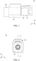
Fig. 1 is a side view showing an assembly according to an embodiment of the present invention. In the figure, a connector is not mated with a mating connector. -
Fig. 2 is a front view showing the assembly ofFig. 1 . -
Fig. 3 is a cross-sectional view showing the assembly ofFig. 2 , taken along line A-A. -
Fig. 4 is a side view showing the assembly ofFig. 1 . In the figure, the connector is mated with the mating connector. -
Fig. 5 is a front view showing the assembly ofFig. 4 . -
Fig. 6 is a cross-sectional view showing the assembly ofFig. 5 , taken along line B-B. -
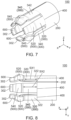
Fig. 7 is a perspective view showing a terminal which is included in the connector of the assembly ofFig. 3 . -
Fig. 8 is a top view showing the terminal ofFig. 7 . -
Fig. 9 is a side view showing the terminal ofFig. 7 . -
Fig. 10 is a cross-sectional view showing the terminal ofFig. 9 , taken along line C-C. -
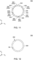
Fig. 11 is a cross-sectional view showing the terminal ofFig. 9 , taken along line D-D. -
Fig. 12 is a cross-sectional view showing the terminal ofFig. 9 , taken along line E-E. -
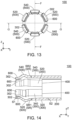
Fig. 13 is a front view showing the terminal ofFig. 7 . -
Fig. 14 is a cross-sectional view showing the terminal ofFig. 13 , taken along line F-F. -
Fig. 15 is a cross-sectional view showing the terminal ofFig. 13 , taken along line G-G. -
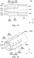
Fig. 16 is a perspective view showing a modification of the terminal ofFig. 7 . -
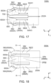
Fig. 17 is a top view showing the terminal ofFig. 16 . -
Fig. 18 is a side view showing the terminal ofFig. 16 . -
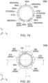
Fig. 19 is a cross-sectional view showing the terminal ofFig. 18 , taken along line H-H. -
Fig. 20 is a front view showing the terminal ofFig. 16 . -
Fig. 21 is a cross-sectional view showing the terminal ofFig. 20 , taken along line I-I. -
Fig. 22 is a cross-sectional view showing the terminal ofFig. 20 , taken along line J-J. -
Fig. 23 is a partially cross-sectional view showing a terminal and a mating terminal ofPatent Document 1. -
Fig. 24 is a perspective view showing the terminal ofFig. 23 . - While the invention is susceptible to various modifications and alternative forms, specific embodiments thereof are shown by way of example in the drawings and will herein be described in detail. It should be understood, however, that the drawings and detailed description thereto are not intended to limit the invention to the particular form disclosed, but on the contrary, the intention is to cover all modifications, equivalents and alternatives falling within the spirit and scope of the present invention as defined by the appended claims.
- As shown in
Fig. 1 , anassembly 10 according to an embodiment of the present invention comprises amating connector 40 and aconnector 20. - As shown in
Fig. 3 , themating connector 40 of the present embodiment comprises amating holding member 42 and amating terminal 850. - Referring to
Fig. 3 , themating holding member 42 of the present embodiment is made of insulator. - Referring to
Fig. 3 , themating terminal 850 of the present embodiment is made of metal. Themating terminal 850 is held by themating holding member 42. - As understood from
Figs. 1 and4 , theconnector 20 of the present embodiment is mateable along a front-rear direction with themating connector 40 which is positioned forward of theconnector 20 in the front-rear direction. In the present embodiment, the front-rear direction is an X-direction. Specifically, forward is a positive X-direction while rearward is a negative X-direction. - As shown in
Fig. 3 , theconnector 20 of the present embodiment comprises a holdingmember 22 and a terminal 100. - Referring to
Fig. 3 , the holdingmember 22 of the present embodiment is made of insulator. The holdingmember 22 has anopening 23 and a matingterminal accommodating portion 24. - As shown in
Fig. 3 , theopening 23 of the present embodiment is positioned at a front end of the holdingmember 22 in the front-rear direction. Theopening 23 connects the matingterminal accommodating portion 24 with the outside of theconnector 20. - As shown in
Fig. 3 , the matingterminal accommodating portion 24 of the present embodiment is positioned rearward of theopening 23 in the front-rear direction. As shown inFig. 6 , the matingterminal accommodating portion 24 accommodates a part of themating terminal 850 when theconnector 20 and themating connector 40 are mated with each other. - Referring to
Figs. 3 and6 , theterminal 100 of the present embodiment is connectable with themating terminal 850 in the front-rear direction. In other words, the terminal 100 is mated with themating terminal 850 when theconnector 20 is mated with themating connector 40. The terminal 100 is held by the holdingmember 22. A part of the terminal 100 is positioned in the matingterminal accommodating portion 24. - Referring to
Fig. 7 , the terminal 100 is made of metal. The terminal 100 is made from bent plate. In other words, the terminal 100 is not formed by cutting a metal block. - As shown in
Fig. 7 , the terminal 100 has abase portion 200, a plurality of supportingportions 300 and a plurality of contact points 500. Thebase portion 200 has a cylindrical shape. - As shown in
Fig. 8 , thebase portion 200 of the present embodiment extends in the front-rear direction. Thebase portion 200 defines a rear end of the terminal 100 in the front-rear direction. As understood fromFigs. 8 and12 , thebase portion 200 is formed by bending a plate to form the cylindrical shape so that edges of the plate face each other. Thebase portion 200 has facingportions 202. It is noted that the facingportions 202 may be connected with each other by crimping, welding or the like. - Referring to
Figs. 8 and9 , each of the supportingportions 300 of the present embodiment is resiliently deformable. Each of the supportingportions 300 extends forward in the front-rear direction from thebase portion 200. The supportingportions 300 are independent from each other.Boundaries 400 between thebase portion 200 and each of the supportingportions 300 are positioned at positions same as each other in the front-rear direction. However, the present invention is not limited thereto, but theboundaries 400 between thebase portion 200 and each of the supportingportions 300 may be positioned at positions different from each other in the front-rear direction. As shown inFig. 11 , the supportingportions 300 are arranged in a circumferential direction about an axis parallel to the front-rear direction. In particular, the supportingportions 300 of the present embodiment are arranged at a constant interval in the circumferential direction. - As shown in
Figs. 8 and9 , the plurality of supportingportions 300 include supportingportions 320 and supportingportions 340. Hereinafter, the supportingportion 320 is also referred to as a first supportingportion 320. In addition, the supportingportion 340 is also referred to as a second supportingportion 340. In other words, the plurality of supportingportions 300 include the first supportingportions 320 and the second supportingportions 340. - As shown in
Fig. 11 , the number of the first supportingportions 320 of the present embodiment is three. However, the present invention is not limited thereto, but the number of the first supportingportions 320 may be other than three. As shown inFig. 8 , in the front-rear direction, a size SX1 of the first supportingportion 320 is smaller than a size SX2 of the second supportingportion 340. That is, in the present embodiment, the first supportingportion 320 is shorter than the second supportingportion 340. The first supportingportion 320 and the second supportingportion 340 are adjacent to each other in the circumferential direction. The first supportingportion 320 has asurface 322 which faces outward in a radial direction. - As shown in
Fig. 11 , in the radial direction, a size SR1 of the first supportingportion 320 is smaller than a size SR2 of the second supportingportion 340. That is, in the present embodiment, the first supportingportion 320 is thinner than the second supportingportion 340. As shown inFig. 14 , the size SR1 of the first supportingportion 320 in the radial direction is smaller than a thickness S2 of thebase portion 200. That is, in the present embodiment, the first supportingportion 320 is thinner than thebase portion 200. - As shown in
Figs. 8 and9 , the number of the second supportingportions 340 of the present embodiment is three. However, the present invention is not limited thereto, but the number of the second supportingportions 340 may be other than three. The second supportingportion 340 has asurface 342 which faces outward in the radial direction. - As shown in
Fig. 11 , the first supportingportions 320 and the second supportingportions 340 are alternately arranged in the circumferential direction. In other words, each of the first supportingportions 320 is arranged between two of the second supportingportions 340 in the circumferential direction, and each of the second supportingportions 340 is arranged between two of the first supportingportions 320 in the circumferential direction. - As shown in
Fig. 11 , thesurfaces portions 300 are positioned on a common circle in a plane perpendicular to the front-rear direction. - Referring to
Figs. 11 and14 , the terminal 100 is manufactured by punching out a blank from a single metal plate, followed by coining inner surfaces of first supportingportions 320 of the blank in the radial direction, and further followed by bending the blank. - As shown in
Figs. 8 and9 , the terminal 100 hasfree ends 302 which correspond to the supportingportions 300, respectively. In other words, each of the supportingportions 300 of the present embodiment is not coupled with any of the other supportingportions 300 at a front of the supportingportion 300. Thus, the supportingportions 300 are resiliently deformable independently of each other as described above. - As shown in
Fig. 8 , in the front-rear direction, each of the free ends 302 of the present embodiment is positioned forward of thecontact point 500 which corresponds to the corresponding supportingportion 300. Thefree end 302 defines a front end of the terminal 100 in the front-rear direction. As shown inFig. 3 , each of the free ends 302 is positioned rearward of theopening 23 in the front-rear direction. Each of the free ends 302 is positioned in the matingterminal accommodating portion 24. - Referring to
Fig. 6 , each of the contact points 500 of the present embodiment is brought into contact with themating terminal 850 when the terminal 100 is connected with themating terminal 850. As shown inFigs. 8 and9 , the contact points 500 are supported by the supportingportions 300, respectively. Referring toFig. 10 , each of the contact points 500 is movable in the radial direction perpendicular to the front-rear direction. - As shown in
Fig. 13 , each of the contact points 500 of the present embodiment protrudes outward in the radial direction. Referring toFigs. 6 and13 , an outer surface of thecontact point 500 in the radial direction is brought into contact with themating terminal 850 when the terminal 100 and themating terminal 850 are mated with each other. However, the present invention is not limited thereto, but thecontact point 500 may protrude inward in the radial direction. In other words, the terminal 100 may be configured so that an inner surface of thecontact point 500 in the radial direction is brought into contact with themating terminal 850 when the terminal 100 and themating terminal 850 are mated with each other. - As described above, the
surfaces portions 300 are positioned on the common circle in the plane perpendicular to the front-rear direction. Accordingly, referring toFigs. 6 and13 , theterminal 100 of the present embodiment has reduced variation of positions of the contact points 500 in the radial direction which are configured to be brought into contact with themating terminal 850. This ensures reliable contact of the contact points 500 with themating terminal 850 when the terminal 100 is connected with themating terminal 850. - As shown in
Fig. 10 , the plurality ofcontact points 500 include contact points 520 and contact points 540. Thecontact point 520 is also referred to as afirst contact point 520. In addition, thecontact point 540 is also referred to as asecond contact point 540. In other words, the plurality ofcontact points 500 include the first contact points 520 and the second contact points 540. - As shown in
Fig. 14 , the first contact points 520 of the present embodiment are resiliently supported by the first supportingportions 320, respectively. The size SR1 of the first supportingportion 320 in the radial direction at a location, which is nearer to thecontact point 520 than to theboundary 400 in the front-rear direction, is smaller than the thickness S2 of thebase portion 200. Each of the first contact points 520 is positioned rearward of any of the second contact points 540 in the front-rear direction. In other words, each of some contact points 520 is positioned rearward of any of the remaining contact points 540 in the front-rear direction. This reduces an insertion force when the terminal 100 is inserted into themating terminal 850. - As shown in
Fig. 8 , the second contact points 540 are resiliently supported by the second supportingportions 340, respectively. Each of the second contact points 540 is positioned forward of any of the first contact points 520 in the front-rear direction. - As described above, in the front-rear direction, the size SX1 of the first supporting
portion 320 is smaller than the size SX2 of the second supportingportion 340. Accordingly, in a case where sizes SR of the supportingportions 300 in the radial direction are same as each other, contact pressure of thecontact point 520, which is supported by the first supportingportion 320, is expected to be higher than contact pressure of thesecond contact point 540 which is supported by the second supportingportion 340. However, the size SR1 of the first supportingportion 320 is smaller than the size SR2 of the second supportingportion 340 in the radial direction as described above. This enables theterminal 100 of the present embodiment to reduce the contact pressure of thecontact point 520 whose contact pressure is expected to be high in the case where the sizes SR of the supportingportions 300 in the radial direction are same as each other. Thus, variation of the contact pressures of the contact points 500 is within a predetermined range. In other words, theterminal 100 of the present embodiment is configured so that contactability of thecontact point 520 is not reduced even if the terminal 100 is repeatedly mated with themating terminal 850. However, the present invention is not limited thereto. Specifically, in at least one of the circumferential direction and the radial direction, a size of each of the first supportingportions 320 should be, at least in part, smaller than a size of any of the second supportingportions 340. That is, in the at least one of the circumferential direction and the radial direction, the size of each of some supportingportions 320 should be, at least in part, smaller than the size of any of the remaining supportingportions 340. This has the same effect as theterminal 100 of the present embodiment. - As shown in
Fig. 10 , the first contact points 520 and the second contact points 540 are alternately arranged in the circumferential direction. In other words, each of the first contact points 520 is arranged between two of the second contact points 540 in the circumferential direction, and each of the second contact points 540 is arranged between two of the first contact points 520 in the circumferential direction. - As described above, each of the first contact points 520 is positioned forward of any of the second contact points 540 in the front-rear direction, and the first contact points 520 and the second contact points 540 are alternately arranged in the circumferential direction. In other words, the positions of the contact points 500, which are adjacent to each other in the circumferential direction, are deviated from each other in the front-rear direction. Thus, in the
terminal 100 of the present embodiment, the contact points 500 are arranged in a manner where their contact pressures are well-balanced. - As shown in
Figs. 8 and9 , the terminal 100 has a plurality offront end portions 600. - As shown in
Figs. 8 and9 , thefront end portions 600 of the present embodiment extend forward in the front-rear direction from the contact points 500, respectively. In the front-rear direction, each of thefront end portions 600 is positioned forward of the supportingportion 300 which corresponds to thecorresponding contact point 500. Thefront end portions 600 form the free ends 302, respectively. As shown inFig. 10 , thefront end portion 600 is positioned inward of thecorresponding contact point 500 in the radial direction. As shown inFig. 14 , a size S1 of thefront end portion 600 in the radial direction is smaller than the thickness S2 of thebase portion 200. In other words, thefront end portion 600 is thinner than thebase portion 200. It is noted that the size S1 of thefront end portion 600 is smaller than the size SR1 of the first supportingportion 320 in the radial direction. Accordingly, even if thefront end portion 600 is resiliently deformed upon the mating of theconnector 20 with themating connector 40, thefront end portion 600 can have a distance from a component of themating connector 40 which is other than themating terminal 850. Thus, even if thefront end portion 600 is resiliently deformed upon the mating of theconnector 20 with themating connector 40, the terminal 100 is prevented from being buckled by abutting against the component. - The structure of the
terminal 100 of theconnector 20 is not limited thereto. The terminal 100 can be modified, for example, as described below. - Referring to
Fig. 16 , a terminal 100A according to a modification of the present invention is made of metal. Similar to theterminal 100 of the aforementioned embodiment, theterminal 100A is made from bent plate. In other words, theterminal 100A is not formed by cutting a metal block. - As shown in
Fig. 16 , theterminal 100A has abase portion 200A, a plurality of contact points 500A, a plurality offront end portions 600A, aslit 700, acoupling portion 800 and a plurality of supportingportions 300A. Thebase portion 200A has a cylindrical shape. - As shown in
Fig. 17 , thebase portion 200A of the present modification extends in the front-rear direction. Thebase portion 200A defines a rear end of the terminal 100A in the front-rear direction. Referring toFig. 19 , thebase portion 200A is formed by bending a plate to form the cylindrical shape so that edges of the plate face each other. Thebase portion 200A has facingportions 202A. It is noted that the facingportions 202A may be connected with each other by crimping, welding or the like. - Referring to
Figs. 6 and18 , each of the contact points 500A of the present modification is brought into contact with themating terminal 850 when the terminal 100A is connected with themating terminal 850. As shown inFigs. 17 and 18 , the contact points 500A are supported by the supportingportions 300A, respectively. Referring toFig. 20 , each of the contact points 500A is movable in the radial direction perpendicular to the front-rear direction. - As shown in
Fig. 20 , each of the contact points 500A of the present modification protrudes outward in the radial direction. Referring toFigs. 6 and20 , an outer surface of thecontact point 500A in the radial direction is brought into contact with themating terminal 850 when the terminal 100A and themating terminal 850 are mated with each other. However, the present invention is not limited thereto, but thecontact point 500A may protrude inward in the radial direction. In other words, the terminal 100A may be configured so that an inner surface of thecontact point 500A in the radial direction is brought into contact with themating terminal 850 when the terminal 100A and themating terminal 850 are mated with each other. - As shown in
Fig. 20 , the plurality ofcontact points 500A include contact points 560, 562, contact points 570, 572 andcontact points contact point first contact point contact point second contact point contact point third contact point contact points 500A include the first contact points 560, 562, the second contact points 570, 572 and the third contact points 580, 582. - As understood from
Figs 17, 18 ,21 and 22 , each of the first contact points 560, 562 is positioned rearward of any of the second contact points 570, 572 and the third contact points 580, 582 in the front-rear direction. Each of the second contact points 570, 572 is positioned forward of any of the first contact points 560, 562 in the front-rear direction. Each of the second contact points 570, 572 is positioned rearward of any of the third contact points 580, 582 in the front-rear direction. Each of the third contact points 580, 582 is positioned forward of any of the first contact points 560, 562 and the second contact points 570, 572 in the front-rear direction. - As shown in
Figs. 17 and 18 , thefront end portions 600A of the present modification extend forward in the front-rear direction from the contact points 500A, respectively. - As shown in
Fig. 20 , theslit 700 of the present modification splits thecoupling portion 800 in the circumferential direction. The number of theslit 700 of the present modification is one. - As shown in
Fig. 20 , thecoupling portion 800 of the present modification has a C-shape. As understood fromFigs. 17 and 18 , thecoupling portion 800 couples thefront end portions 600A with each other except for theslit 700. - Referring to
Figs. 17 and 18 , each of the supportingportions 300A of the present modification is resiliently deformable. Each of the supportingportions 300A extends forward in the front-rear direction from thebase portion 200A. As described above, the contact points 500A are supported by the supportingportions 300A, respectively, thefront end portions 600A extend forward from the contact points 500A, respectively, and thecoupling portion 800 couples thefront end portions 600A with each other except forslit 700. Thus, unlike to the supportingportions 300 of the aforementioned embodiment, the supportingportions 300A of the present modification are not independent from each other. As shown inFig. 19 the supportingportions 300A are arranged in the circumferential direction about the axis parallel to the front-rear direction. - As shown in
Figs. 17 and 18 , the plurality of supportingportions 300A include supportingportions portions portions portion portion portion portion portion - Referring to
Figs. 17 and21 , in the front-rear direction, a size SAX1 of each of the first supportingportions portions portions Fig. 19 , the first supportingportions portion 360 is positioned between the second supportingportion 370 and the third supportingportion 380 in the circumferential direction. The first supportingportion 362 is positioned between the second supportingportion 372 and the third supportingportion 382 in the circumferential direction. The first supportingportion 360 has asurface 3602 which faces outward in the radial direction. The first supportingportion 362 has asurface 3622 which faces outward in the radial direction. - Referring to
Figs. 17 and21 , the size SAX2 of each of the second supportingportions portions portions portions Fig. 19 , the second supportingportions portion 370 is positioned between the first supportingportion 360 and the third supportingportion 382 in the circumferential direction. The second supportingportion 372 is positioned between the first supportingportion 362 and the third supportingportion 380 in the circumferential direction. The second supportingportion 370 has asurface 3702 which faces outward in the radial direction. The second supportingportion 372 has asurface 3722 which faces outward in the radial direction. - Referring to
Figs. 17 and21 , the size SAX3 of each of the third supportingportions portions portions Fig. 19 , the third supportingportions portion 380 is positioned between the first supportingportion 360 and the second supportingportion 372 in the circumferential direction. The third supportingportion 382 is positioned between the first supportingportion 362 and the second supportingportion 370 in the circumferential direction. The third supportingportion 380 has asurface 3802 which faces outward in the radial direction. The third supportingportion 382 has asurface 3822 which faces outward in the radial direction. - As shown in
Figs. 17 and 18 , thefirst contact point 560 is resiliently supported by the first supportingportion 360, and thefirst contact point 562 is resiliently supported by the first supportingportion 362. As shown inFig. 22 , thesecond contact point 570 is resiliently supported by the second supportingportion 370, and thesecond contact point 572 is resiliently supported by the second supportingportion 372. As shown inFigs. 17 and21 , thethird contact point 580 is resiliently supported by the third supportingportion 380, and thethird contact point 582 is resiliently supported by the third supportingportion 382. - As described above, each of the first contact points 560, 562 is positioned rearward of any of the second contact points 570, 572 and the third contact points 580, 582 in the front-rear direction. In other words, each of some contact points 560, 562 is positioned rearward of any of the remaining contact points 570, 572, 580, 582 in the front-rear direction. This reduces an insertion force when the terminal 100A is inserted into the
mating terminal 850. - As shown in
Fig. 19 , the supportingportions - Referring to
Figs. 19 and 20 , the supportingportions portions 300A are positioned farthest from theslit 700 among the plurality of supportingportions 300A. Accordingly, contact pressure of each of the contact points 560, 580, which are supported by the supportingportions portions 300A in the radial direction are same as each other. - As shown in
Fig. 19 , in the radial direction, a size SAR1 of the supportingportion 360 is smaller than the size SAR3 of any of the supportingportions portion 380 is smaller than the size SAR3 of any of the supportingportions portions 300A in the radial direction are same as each other. Thus, variation of the contact pressures of the contact points 500A is within a predetermined range. In other words, the terminal 100A of the present modification is configured so that contactability of thecontact point 500A is not reduced even if the terminal 100A is repeatedly mated with themating terminal 850. However, the present invention is not limited thereto. Specifically, in at least one of the circumferential direction and the radial direction, a size of each of some supportingportions portions - Although the terminal 100A of the aforementioned modification is configured so that the two supporting
portions slit 700 among the supportingportions 300A, the present invention is not limited thereto. Specifically, the terminal 100A may be modified so that one of the supportingportions 300A is positioned farthest from theslit 700 among the supportingportions 300A. More specifically, the terminal 100A may be configured as follows: one or two of the plurality of supportingportions 300A is/are positioned farthest from theslit 700 among the plurality of supportingportions 300A; and, in at least one of the circumferential direction and the radial direction, size(s) of the one or two supporting portion(s) 300A is/are, at least in part, smaller than a size of any of remaining ones of the supportingportions 300A. This has the same effect as the terminal 100A of the present modification. - As shown in
Fig. 19 , thesurfaces portions 300A are positioned on a common circle in the plane perpendicular to the front-rear direction. Accordingly, referring toFigs. 6 and20 , the terminal 100A of the present modification has reduced variation of positions of the contact points 500A in the radial direction which are configured to be brought into contact with themating terminal 850. This ensures reliable contact of the contact points 500A with themating terminal 850 when the terminal 100A is connected with themating terminal 850. - Referring to
Fig. 19 , theterminal 100A is manufactured by punching out a blank from a single metal plate, followed by coining inner surfaces ofsupport portions - Although the specific explanation about the present invention is made above referring to the embodiments, the present invention is not limited thereto and is susceptible to various modifications and alternative forms.
- Although the terminal 100A of the present modification has the
single slit 700, the present invention is not limited thereto. Specifically, the terminal 100A may have two or more of theslits 700. Also, in this case, the size of the supportingportion 300A, which is positioned farthest from theslits 700 among the plurality of supportingportion 300A, must be, at least in part, smaller than the size of any of remaining ones of the supportingportions 300A in at least one of the circumferential direction and the radial direction. This has the same effect as the terminal 100A of the present modification. - The present application is based on a Japanese patent application of
JP2021-206097 filed before the Japan Patent Office on December 20, 2021 - While there has been described what is believed to be the preferred embodiment of the invention, those skilled in the art will recognize that other and further modifications may be made thereto without departing from the spirit of the invention, and it is intended to claim all such embodiments that fall within the true scope of the invention.
-
- 10
- assembly
- 20
- connector
- 22
- holding member
- 23
- opening
- 24
- mating terminal accommodating portion
- 40
- mating connector
- 42
- mating holding member
- 100, 100A
- terminal
- 200, 200A
- base portion
- 202, 202A
- facing portion
- 300, 300A
- supporting portion
- 302
- free end
- 320
- first supporting portion (supporting portion)
- 322
- surface
- 340
- second supporting portion (supporting portion)
- 342
- surface
- 360
- first supporting portion (supporting portion)
- 3602
- surface
- 362
- first supporting portion (supporting portion)
- 3622
- surface
- 370
- second supporting portion (supporting portion)
- 3702
- surface
- 372
- second supporting portion (supporting portion)
- 3722
- surface
- 380
- third supporting portion (supporting portion)
- 3802
- surface
- 382
- third supporting portion (supporting portion)
- 3822
- surface
- 400
- boundary
- 500, 500A
- contact point
- 520
- first contact point (contact point)
- 540
- second contact point (contact point)
- 560
- first contact point (contact point)
- 562
- first contact point (contact point)
- 570
- second contact point (contact point)
- 572
- second contact point (contact point)
- 580
- third contact point (contact point)
- 582
- third contact point (contact point)
- 600, 600A
- front end portion
- 700
- slit
- 800
- coupling portion
- 850
- mating terminal
- S1
- size
- S2
- thickness
- SR
- size
- SR1
- size
- SR2
- size
- SX1
- size
- SX2
- size
- SAR
- size
- SAR1
- size
- SAR2
- size
- SAR3
- size
- SAX1
- size
- SAX2
- size
- SAX3
- size
Claims (6)
- A terminal connectable with a mating terminal in a front-rear direction, wherein:the terminal has a base portion, a plurality of supporting portions and a plurality of contact points;the base portion has a cylindrical shape;each of the supporting portions is resiliently deformable and extends forward in the front-rear direction form the base portion;the supporting portions are arranged in a circumferential direction about an axis parallel to the front-rear direction;each of the contact points is brought into contact with the mating terminal when the terminal is connected with the mating terminal;the contact points are supported by the supporting portions, respectively;each of the contact points is movable in a radial direction perpendicular to the front-rear direction;each of some of the contact points is positioned rearward of any of remaining ones of the contact points in the front-rear direction; andin at least one of the circumferential direction and the radial direction, a size of each of some of the supporting portions is, at least in part, smaller than a size of any of remaining ones of the supporting portions.
- The terminal as recited in claim 1, wherein:the terminal has a plurality of front end portions, a slit and a coupling portion;the front end portions extend forward in the front-rear direction from the contact points, respectively;the coupling portion has a C-shape and couples the front end portions with each other expect for the slit;one or two of the plurality of supporting portions is/are positioned farthest from the slit among the plurality of supporting portions; andin at least one of the circumferential direction and the radial direction, size(s) of the one or two supporting portion(s) is/are, at least in part, smaller than a size of any of remaining ones of the supporting portions.
- The terminal as recited in claim 1, wherein:the supporting portions are independent from each other;the terminal has boundaries between the base portion and each of the supporting portions;the boundaries are positioned at positions same as each other in the front-rear direction;the terminal has free ends which correspond to the supporting portions, respectively;in the front-rear direction, each of the free ends is positioned forward of the contact point which corresponds to the corresponding supporting portion;the plurality of supporting portions include a first supporting portion and a second supporting portion;in the front-rear direction, a size of the first supporting portion is smaller than a size of the second supporting portion; andin at least one of the circumferential direction and the radial direction, a size of the first supporting portion is, at least in part, smaller than a size of the second supporting portion.
- The terminal as recited in claim 3, wherein:each of the contact points protrudes outward in the radial direction;each of the supporting portions has a surface which faces outward in the radial direction; andthe surfaces of all of the plurality of supporting portions are positioned on a common circle in a plane perpendicular to the front-rear direction.
- The terminal as recited in claim 3 or claim 4, wherein:the terminal has a plurality of front end portions;the front end portions extend forward in the front-rear direction from the contact points, respectively;the front end portions form the free ends, respectively; andeach of the front end portions is thinner than the base portion.
- The terminal as recited in one of claims 1 to 5, wherein the terminal is made from bent plate.
Priority Applications (1)
| Application Number | Priority Date | Filing Date | Title |
|---|---|---|---|
| EP25226991.5A EP4697516A3 (en) | 2021-12-20 | 2022-10-28 | Terminal |
Applications Claiming Priority (2)
| Application Number | Priority Date | Filing Date | Title |
|---|---|---|---|
| JP2021206097A JP7348258B2 (en) | 2021-12-20 | 2021-12-20 | terminal |
| PCT/JP2022/040361 WO2023119870A1 (en) | 2021-12-20 | 2022-10-28 | Terminal |
Related Child Applications (1)
| Application Number | Title | Priority Date | Filing Date |
|---|---|---|---|
| EP25226991.5A Division EP4697516A3 (en) | 2021-12-20 | 2022-10-28 | Terminal |
Publications (2)
| Publication Number | Publication Date |
|---|---|
| EP4432479A1 true EP4432479A1 (en) | 2024-09-18 |
| EP4432479A4 EP4432479A4 (en) | 2025-02-26 |
Family
ID=86901998
Family Applications (2)
| Application Number | Title | Priority Date | Filing Date |
|---|---|---|---|
| EP25226991.5A Pending EP4697516A3 (en) | 2021-12-20 | 2022-10-28 | Terminal |
| EP22910591.1A Pending EP4432479A4 (en) | 2021-12-20 | 2022-10-28 | TERMINAL |
Family Applications Before (1)
| Application Number | Title | Priority Date | Filing Date |
|---|---|---|---|
| EP25226991.5A Pending EP4697516A3 (en) | 2021-12-20 | 2022-10-28 | Terminal |
Country Status (5)
| Country | Link |
|---|---|
| US (1) | US20250141141A1 (en) |
| EP (2) | EP4697516A3 (en) |
| JP (1) | JP7348258B2 (en) |
| CN (1) | CN118355569A (en) |
| WO (1) | WO2023119870A1 (en) |
Family Cites Families (14)
| Publication number | Priority date | Publication date | Assignee | Title |
|---|---|---|---|---|
| CA2272458C (en) * | 1998-06-25 | 2008-03-18 | Leslie Laszlo Kerek | Hoodless electrical socket connector |
| JP2014078373A (en) * | 2012-10-10 | 2014-05-01 | Auto Network Gijutsu Kenkyusho:Kk | Multi-contact type female terminal |
| JP6034755B2 (en) * | 2013-06-14 | 2016-11-30 | 矢崎総業株式会社 | Terminal structure |
| CN107112673A (en) * | 2014-10-10 | 2017-08-29 | 株式会社藤仓 | Terminal and its manufacture method |
| JP6583032B2 (en) * | 2016-02-10 | 2019-10-02 | 住友電装株式会社 | Female terminal |
| CN113571936A (en) * | 2016-02-26 | 2021-10-29 | 罗森伯格高频技术有限及两合公司 | Contact sleeve for an electrical plug connector |
| JP6623853B2 (en) * | 2016-03-10 | 2019-12-25 | Smk株式会社 | Contact structure |
| JP2018067496A (en) * | 2016-10-21 | 2018-04-26 | 住友電装株式会社 | Shield terminal and outer conductor terminal |
| US9917390B1 (en) * | 2016-12-13 | 2018-03-13 | Carlisle Interconnect Technologies, Inc. | Multiple piece contact for an electrical connector |
| JP6845438B2 (en) * | 2018-01-26 | 2021-03-17 | タツタ電線株式会社 | How to manufacture connector terminals, connectors with connector terminals, and connector terminals |
| EP3641068B1 (en) * | 2018-10-16 | 2021-01-27 | ODU GmbH & Co. KG | Connecting plug and socket with lamella basket |
| DK3761455T3 (en) * | 2019-07-01 | 2022-08-29 | Odu Gmbh & Co Kg | Connection plug with a center pin and lamella sleeve and connection socket with lamella sleeve |
| TWM598550U (en) * | 2020-03-05 | 2020-07-11 | 連展科技股份有限公司 | Power connector with crown spring |
| CN113410685A (en) * | 2021-07-15 | 2021-09-17 | 长春捷翼汽车零部件有限公司 | Terminal with stamping spring plate structure |
-
2021
- 2021-12-20 JP JP2021206097A patent/JP7348258B2/en active Active
-
2022
- 2022-10-28 WO PCT/JP2022/040361 patent/WO2023119870A1/en not_active Ceased
- 2022-10-28 US US18/721,176 patent/US20250141141A1/en active Pending
- 2022-10-28 CN CN202280084119.4A patent/CN118355569A/en active Pending
- 2022-10-28 EP EP25226991.5A patent/EP4697516A3/en active Pending
- 2022-10-28 EP EP22910591.1A patent/EP4432479A4/en active Pending
Also Published As
| Publication number | Publication date |
|---|---|
| US20250141141A1 (en) | 2025-05-01 |
| WO2023119870A1 (en) | 2023-06-29 |
| EP4697516A3 (en) | 2026-05-13 |
| JP2023091383A (en) | 2023-06-30 |
| CN118355569A (en) | 2024-07-16 |
| EP4432479A4 (en) | 2025-02-26 |
| JP7348258B2 (en) | 2023-09-20 |
| EP4697516A2 (en) | 2026-02-18 |
Similar Documents
| Publication | Publication Date | Title |
|---|---|---|
| US7806737B2 (en) | Stamped beam connector | |
| US6220899B1 (en) | Electrical connector jack for securely holding a plug | |
| EP2511989A1 (en) | Connector and assembling method therefor | |
| JPS6343275A (en) | Contact socket for improvement of contact pressure | |
| EP0136836A2 (en) | Female electrical terminal having improved contactor block structure | |
| CN118235300A (en) | Connector, connector assembly, and tool and method for assembling connector assembly | |
| EP3240114B1 (en) | Electrical contact terminal and method to manufacture the same | |
| US6402575B1 (en) | Tab of terminal fitting | |
| EP4697516A2 (en) | Terminal | |
| EP0214022B1 (en) | Contact for connector | |
| US10720717B2 (en) | Conductive terminal and connector | |
| CN110224253A (en) | Connection terminal | |
| US11888266B2 (en) | Connector shielding with a guiding protrusion | |
| KR102871391B1 (en) | Connection terminal | |
| EP4525215A1 (en) | Floating connector and contact for such a floating connector | |
| EP0727843B1 (en) | Asymmetric electrical receptacle terminal | |
| JP2022037547A (en) | Terminal fittings and chain terminals | |
| JP2012022826A (en) | Socket contact | |
| US9685725B2 (en) | Connector | |
| EP4231460A1 (en) | Contact element, electrical connector and electrical connector assembly | |
| US12261402B2 (en) | Spring connector | |
| US11611168B2 (en) | Cable connector with contact holder latching to the outer shell | |
| JP3237310U (en) | Coaxial plug connector | |
| US11381009B2 (en) | Contact and connector | |
| US20250112391A1 (en) | Connector |
Legal Events
| Date | Code | Title | Description |
|---|---|---|---|
| STAA | Information on the status of an ep patent application or granted ep patent |
Free format text: STATUS: THE INTERNATIONAL PUBLICATION HAS BEEN MADE |
|
| PUAI | Public reference made under article 153(3) epc to a published international application that has entered the european phase |
Free format text: ORIGINAL CODE: 0009012 |
|
| STAA | Information on the status of an ep patent application or granted ep patent |
Free format text: STATUS: REQUEST FOR EXAMINATION WAS MADE |
|
| 17P | Request for examination filed |
Effective date: 20240614 |
|
| AK | Designated contracting states |
Kind code of ref document: A1 Designated state(s): AL AT BE BG CH CY CZ DE DK EE ES FI FR GB GR HR HU IE IS IT LI LT LU LV MC ME MK MT NL NO PL PT RO RS SE SI SK SM TR |
|
| RAP3 | Party data changed (applicant data changed or rights of an application transferred) |
Owner name: JAPAN AVIATION ELECTRONICS INDUSTRY, LIMITED |
|
| A4 | Supplementary search report drawn up and despatched |
Effective date: 20250129 |
|
| RIC1 | Information provided on ipc code assigned before grant |
Ipc: H01R 13/11 20060101ALI20250123BHEP Ipc: H01R 13/24 20060101ALI20250123BHEP Ipc: H01R 13/05 20060101AFI20250123BHEP |
|
| DAV | Request for validation of the european patent (deleted) | ||
| DAX | Request for extension of the european patent (deleted) | ||
| STAA | Information on the status of an ep patent application or granted ep patent |
Free format text: STATUS: EXAMINATION IS IN PROGRESS |
|
| 17Q | First examination report despatched |
Effective date: 20250930 |
|
| GRAP | Despatch of communication of intention to grant a patent |
Free format text: ORIGINAL CODE: EPIDOSNIGR1 |
|
| STAA | Information on the status of an ep patent application or granted ep patent |
Free format text: STATUS: GRANT OF PATENT IS INTENDED |
|
| INTG | Intention to grant announced |
Effective date: 20260421 |
|
| GRAS | Grant fee paid |
Free format text: ORIGINAL CODE: EPIDOSNIGR3 |