EP4432405A1 - Brennstoffzellenanlage mit einem festoxidbrennstoffzellensystem und verfahren zum betrieb davon - Google Patents
Brennstoffzellenanlage mit einem festoxidbrennstoffzellensystem und verfahren zum betrieb davon Download PDFInfo
- Publication number
- EP4432405A1 EP4432405A1 EP23305339.6A EP23305339A EP4432405A1 EP 4432405 A1 EP4432405 A1 EP 4432405A1 EP 23305339 A EP23305339 A EP 23305339A EP 4432405 A1 EP4432405 A1 EP 4432405A1
- Authority
- EP
- European Patent Office
- Prior art keywords
- gas flow
- heat exchanger
- flow
- tube bundle
- oxygen
- Prior art date
- Legal status (The legal status is an assumption and is not a legal conclusion. Google has not performed a legal analysis and makes no representation as to the accuracy of the status listed.)
- Pending
Links
Images


Classifications
-
- H—ELECTRICITY
- H01—ELECTRIC ELEMENTS
- H01M—PROCESSES OR MEANS, e.g. BATTERIES, FOR THE DIRECT CONVERSION OF CHEMICAL ENERGY INTO ELECTRICAL ENERGY
- H01M8/00—Fuel cells; Manufacture thereof
- H01M8/04—Auxiliary arrangements, e.g. for control of pressure or for circulation of fluids
- H01M8/04007—Auxiliary arrangements, e.g. for control of pressure or for circulation of fluids related to heat exchange
- H01M8/04067—Heat exchange or temperature measuring elements, thermal insulation, e.g. heat pipes, heat pumps, fins
- H01M8/04074—Heat exchange unit structures specially adapted for fuel cell
-
- H—ELECTRICITY
- H01—ELECTRIC ELEMENTS
- H01M—PROCESSES OR MEANS, e.g. BATTERIES, FOR THE DIRECT CONVERSION OF CHEMICAL ENERGY INTO ELECTRICAL ENERGY
- H01M8/00—Fuel cells; Manufacture thereof
- H01M8/04—Auxiliary arrangements, e.g. for control of pressure or for circulation of fluids
- H01M8/04007—Auxiliary arrangements, e.g. for control of pressure or for circulation of fluids related to heat exchange
- H01M8/04014—Heat exchange using gaseous fluids; Heat exchange by combustion of reactants
-
- H—ELECTRICITY
- H01—ELECTRIC ELEMENTS
- H01M—PROCESSES OR MEANS, e.g. BATTERIES, FOR THE DIRECT CONVERSION OF CHEMICAL ENERGY INTO ELECTRICAL ENERGY
- H01M8/00—Fuel cells; Manufacture thereof
- H01M8/04—Auxiliary arrangements, e.g. for control of pressure or for circulation of fluids
- H01M8/04007—Auxiliary arrangements, e.g. for control of pressure or for circulation of fluids related to heat exchange
- H01M8/04014—Heat exchange using gaseous fluids; Heat exchange by combustion of reactants
- H01M8/04022—Heating by combustion
-
- H—ELECTRICITY
- H01—ELECTRIC ELEMENTS
- H01M—PROCESSES OR MEANS, e.g. BATTERIES, FOR THE DIRECT CONVERSION OF CHEMICAL ENERGY INTO ELECTRICAL ENERGY
- H01M8/00—Fuel cells; Manufacture thereof
- H01M8/04—Auxiliary arrangements, e.g. for control of pressure or for circulation of fluids
- H01M8/04082—Arrangements for control of reactant parameters, e.g. pressure or concentration
- H01M8/04089—Arrangements for control of reactant parameters, e.g. pressure or concentration of gaseous reactants
- H01M8/04097—Arrangements for control of reactant parameters, e.g. pressure or concentration of gaseous reactants with recycling of the reactants
-
- H—ELECTRICITY
- H01—ELECTRIC ELEMENTS
- H01M—PROCESSES OR MEANS, e.g. BATTERIES, FOR THE DIRECT CONVERSION OF CHEMICAL ENERGY INTO ELECTRICAL ENERGY
- H01M8/00—Fuel cells; Manufacture thereof
- H01M8/06—Combination of fuel cells with means for production of reactants or for treatment of residues
- H01M8/0662—Treatment of gaseous reactants or gaseous residues, e.g. cleaning
- H01M8/0668—Removal of carbon monoxide or carbon dioxide
-
- H—ELECTRICITY
- H01—ELECTRIC ELEMENTS
- H01M—PROCESSES OR MEANS, e.g. BATTERIES, FOR THE DIRECT CONVERSION OF CHEMICAL ENERGY INTO ELECTRICAL ENERGY
- H01M8/00—Fuel cells; Manufacture thereof
- H01M8/06—Combination of fuel cells with means for production of reactants or for treatment of residues
- H01M8/0662—Treatment of gaseous reactants or gaseous residues, e.g. cleaning
- H01M8/0675—Removal of sulfur
-
- H—ELECTRICITY
- H01—ELECTRIC ELEMENTS
- H01M—PROCESSES OR MEANS, e.g. BATTERIES, FOR THE DIRECT CONVERSION OF CHEMICAL ENERGY INTO ELECTRICAL ENERGY
- H01M8/00—Fuel cells; Manufacture thereof
- H01M8/10—Fuel cells with solid electrolytes
- H01M8/12—Fuel cells with solid electrolytes operating at high temperature, e.g. with stabilised ZrO2 electrolyte
- H01M2008/1293—Fuel cells with solid oxide electrolytes
-
- H—ELECTRICITY
- H01—ELECTRIC ELEMENTS
- H01M—PROCESSES OR MEANS, e.g. BATTERIES, FOR THE DIRECT CONVERSION OF CHEMICAL ENERGY INTO ELECTRICAL ENERGY
- H01M8/00—Fuel cells; Manufacture thereof
- H01M8/04—Auxiliary arrangements, e.g. for control of pressure or for circulation of fluids
- H01M8/04082—Arrangements for control of reactant parameters, e.g. pressure or concentration
- H01M8/04089—Arrangements for control of reactant parameters, e.g. pressure or concentration of gaseous reactants
- H01M8/04119—Arrangements for control of reactant parameters, e.g. pressure or concentration of gaseous reactants with simultaneous supply or evacuation of electrolyte; Humidifying or dehumidifying
- H01M8/04156—Arrangements for control of reactant parameters, e.g. pressure or concentration of gaseous reactants with simultaneous supply or evacuation of electrolyte; Humidifying or dehumidifying with product water removal
- H01M8/04164—Arrangements for control of reactant parameters, e.g. pressure or concentration of gaseous reactants with simultaneous supply or evacuation of electrolyte; Humidifying or dehumidifying with product water removal by condensers, gas-liquid separators or filters
-
- H—ELECTRICITY
- H01—ELECTRIC ELEMENTS
- H01M—PROCESSES OR MEANS, e.g. BATTERIES, FOR THE DIRECT CONVERSION OF CHEMICAL ENERGY INTO ELECTRICAL ENERGY
- H01M8/00—Fuel cells; Manufacture thereof
- H01M8/06—Combination of fuel cells with means for production of reactants or for treatment of residues
- H01M8/0606—Combination of fuel cells with means for production of reactants or for treatment of residues with means for production of gaseous reactants
- H01M8/0612—Combination of fuel cells with means for production of reactants or for treatment of residues with means for production of gaseous reactants from carbon-containing material
- H01M8/0618—Reforming processes, e.g. autothermal, partial oxidation or steam reforming
-
- Y—GENERAL TAGGING OF NEW TECHNOLOGICAL DEVELOPMENTS; GENERAL TAGGING OF CROSS-SECTIONAL TECHNOLOGIES SPANNING OVER SEVERAL SECTIONS OF THE IPC; TECHNICAL SUBJECTS COVERED BY FORMER USPC CROSS-REFERENCE ART COLLECTIONS [XRACs] AND DIGESTS
- Y02—TECHNOLOGIES OR APPLICATIONS FOR MITIGATION OR ADAPTATION AGAINST CLIMATE CHANGE
- Y02E—REDUCTION OF GREENHOUSE GAS [GHG] EMISSIONS, RELATED TO ENERGY GENERATION, TRANSMISSION OR DISTRIBUTION
- Y02E60/00—Enabling technologies; Technologies with a potential or indirect contribution to GHG emissions mitigation
- Y02E60/30—Hydrogen technology
- Y02E60/50—Fuel cells
Definitions
- the present invention concerns a fuel cell installation for the production of an electric current by electrochemical reaction between a combustible fluid and dioxygen of the air.
- the fuel fluid is typically a mixture of gas such as hydrogen, carbon monoxide, methane, propane, butane, fermentation gases, gasified biomass, and/or paint vapors.
- the fuel may also consist of a liquid fuel such as methanol, ethanol or fuel, in particular such as diesel or gasoline.
- the fuel cell system typically consists of one or more solid oxide fuel cells (SOFC).
- SOFC solid oxide fuel cells
- Such cells are mainly intended for stationary applications with an output power ranging from 1 kW to several MW.
- a SOFC element generally consists of four layers, three of which are ceramics.
- a single cell consisting of the four superposed layers has a typical thickness of a few millimeters. Tens of such cells are then superimposed in series to form a stack.
- oxygen ions which are formed on the cathode side due to electrochemical reduction of molecular oxygen (dioxygen of air), are conducted through a solid oxide membrane used as an electrolyte at high temperature, in order to react with the gaseous fuel, e.g. hydrogen, on the anode side which is diffused through the anode to the anode/electrolyte interface.
- gaseous fuel e.g. hydrogen
- Such electrochemical reaction leads to the release of electrons that are transported through external circuit to produce electricity.
- the electrochemical reaction between oxygen ions and the fuel is complete, the amount of oxygen ions generated in the SOFC element is insufficient for consuming the entire (re-formed) fuel. A large quantity of non-consumed fuel is thus necessarily recovered at the outlet of the SOFC element.
- the conversion rate of the liquid fuel in a SOFC element is conventionally on the order of 60%.
- a portion of the gas leaving the anode, comprising the carbon dioxide formed, is recycled toward the anode of the cell in order to consume the portion of fuel which did not react, thus increasing the efficiency of the cell.
- the remaining portion of the flow leaving the anode is sent into a catalytic burner wherein same is burned with the oxygen-depleted air flow recovered at the outlet of the cathode of the SOFC element.
- the concentration of carbon dioxide in the gas coming out from the catalytic burner is very low, typically less than or equal to 8 % molar. Indeed, the portion of the anodic flow introduced into the catalytic burner is mixed with oxygen-depleted air coming out of the cathode. Such mixing step then has the effect of significantly reducing the concentration of carbon dioxide in the effluents to be treated.
- the recovery of carbon dioxide present in such a low concentration requires the use of a liquid solvent with a very high regeneration rate, typically the use of a perfectly regenerated liquid solvent, which means a very high energy consumption.
- the oxygen in the air present after the burner can lead to problems of degradation of the liquid solvent, especially the amine compound.
- Such installations further require expensive and very bulky equipment such as a stripping column, along with reboiling and condensation systems.
- SOFC operating pressures and temperatures.
- SOFC structure usability and durability at high pressure limit the SOFC application to pressure level lower than 3 atm. This pressure level has impact on the sizing of the installation since at lower pressure the volumetric flows are higher and thus it results in larger equipment sizing, affecting the applicability of SOFC in area constraint applications such as marine transport, onshore applications and for offshore applications.
- SOFC operates at high temperatures, typically in the order of 800°C.
- the fuel used in the SOFC must thus be pre-heated to about 600°C, making it necessary to use additional heating systems that are both energy and space-consuming.
- the goal of the invention is thus to provide a fuel cell installation allowing an efficient and reliable production of an electric current, with reduced energy consumption and footprint.
- the subject matter of the invention is a fuel cell installation comprising :
- the vertically arranged installation of the first and second heat exchanger systems allows an efficient utilization of the heat generated by the fuel cell unit and the reduction of the temperature of the flows produced by the same, while having a reduced footprint thanks to the stacking of the heat exchangers and of the fuel cell unit.
- the installation according to the invention can comprise one or a plurality of the following features, taken alone or in any technically possible combination:
- the invention further relates to a method of operating a fuel cell installation as define above, comprising the following steps:
- the method according to the invention can comprise one or a plurality of the following features, taken alone or in any technically possible combination
- FIG. 1 An installation 10 according to the invention is shown schematically in Fig. 1 .
- the installation 10 is intended for the production of an electric current from a fuel gas flow 14 and an oxygen-rich gas flow 16.
- the installation 10 is also intended for the recovery, as effluents, of an anodic gas flow 18 and of a cathodic gas flow 20, also called oxygen-depleted gas flow 20.
- the anodic gas flow 18 typically contains hydrogen, water vapor, carbon monoxide, carbon dioxide, some unreacted hydrocarbon gas, such as methane and other reaction byproducts and impurities.
- the cathodic gas flow 20, also called oxygen-depleted cathodic gas flow 20, is oxygen-depleted air.
- the installation 10 may be used for on-shore, off-shore or marine applications.
- the installation 10 is connected upstream to a storage unit 22 intended for storing the fuel gas.
- the storage unit 22 can be replaced by a gas distribution network for conveying the fuel gas 14 into the installation 10 according to the invention.
- the installation 10 preferably comprises a pump and compressor system 24 for conveying atmospheric air 25, compressed if appropriate, into the installation 10 according to the invention.
- pump and compressor system 24 can be replaced by an additional storage system (not shown).
- the fuel gas flow 14 typically comprises hydrogen; carbon monoxide; natural gas containing mainly methane along with lower amounts of ethane, propane, butane and heavier hydrocarbons; fermentation gases; gasified biomass; paint vapors or any of the mixtures thereof.
- the fuel gas flow 14 is a methane flow.
- the fuel gas flow 14 coming from the storage unit 22 is at a pressure ranging from 1 atm to 3 bara (absolute bars), more preferentially from 1 atm to 1.5 bara (absolute bars).
- the oxygen-rich gas flow 16 typically has a concentration of oxygen of at least 10% by volume, preferentially from 15% to 25% by volume of oxygen.
- the oxygen-rich gas flow 16 is an air flow.
- the oxygen-rich gas flow 16 coming from the pump and compressor system 24 is at a pressure ranging from 1 atm to 3 bara (absolute bars).
- the installation 10 is connected downstream to a collecting installation 26 for collecting at least part the oxygen-depleted gas flow 20 for post-treatment or for discharging the oxygen-depleted gas flow 20 directly into the atmosphere.
- the oxygen-depleted gas flow 20 is discharged directly into the atmosphere at the collecting installation 26.
- the oxygen-depleted gas flow 20 is collected in the installation 26 in order to be conveyed to another installation where same will be consumed or converted.
- the installation 10 comprises a pretreatment unit 28, intended for pre-heating the incoming gas flows 14, 16, and a fuel cell unit 30.
- the installation 10 further comprises a carbon capture unit 34 for sequestering carbon dioxide produced by the fuel cell unit 30.
- the storage unit 22 (or the gas distribution network) is connected to an inlet 36 of the pretreatment unit 28 so that the fuel gas flow 14 is injected into the pretreatment unit 28.
- the fuel gas flow 14 is advantageously mixed with a recycled flow 38 recovered at an outlet of the carbon capture unit 34 in order to form a fuel feed flow.
- the nature of the recycled flow 38 is described in detail hereinafter.
- the pretreatment unit 28 is intended for forming and preheating the fuel feed flow to form a heated fuel flow 50 before it is introduced into the fuel cell unit 30.
- the pretreatment unit 28 is also intended for preheating the oxygen-rich gas flow 16 to form a heated oxygen-rich gas flow 52 before it is introduced into the fuel cell unit 30.
- the fuel cell unit 30 is intended for producing the electric current from the heated fuel flow 50 and the heated oxygen-rich gas flow 52 in order to form the anodic gas flow 18 and the cathodic gas flow 20 at the outlet.
- the carbon capture unit 34 is intended for recovering at least part of the anodic gas flow 18 and for forming the recycled flow 38
- the pretreatment unit 28 is shown in more details on Figure 2 .
- the pretreatment unit 28 comprises a first heat exchanger system 42 (also called first heat exchanger 42) intended for heating the fuel feed flow and a second heat exchanger system 44 (also called second heat exchanger 44) intended for heating the oxygen-rich gas flow 16, before the introduction thereof into the fuel cell unit 30.
- first heat exchanger system 42 also called first heat exchanger 42
- second heat exchanger 44 also called second heat exchanger 44
- the pretreatment unit 28 comprises a supplemental furnace 46.
- a heat exchanger system comprises at least one heat exchanger.
- a heat exchanger system can thus comprise one heat exchanger or a plurality of heat exchangers associated with each other.
- Each heat exchanger system 42, 44 includes an enclosure 420, 440 defining a vertical circulation pipe 422, 442 for a gas flow along a circulation axis, extending vertically between a gas inlet 424, 444 and a gas outlet 426, 446.
- the vertical circulation axis is substantially parallel to a vertical elevation axis A.
- substantially parallel we mean that the circulation axis and the vertical elevation axis define together an angle of less than 5°.
- each enclosure 420, 440 are located above the gas inlet 424, 444. More precisely, the gas inlet 424, 444 are arranged at the bottom of enclosure 420, 440 and the gas outlets 426, 446 are located at the top of the enclosure 420, 440.
- the gas flow penetrating the enclosure 420, 440 through the gas inlet 424, 444 has typically a temperature comprised between 700 0 C and 900 0 C, preferably around 800°C and is under a pressure comprised between 1 atm and 3 bara (absolute bars). As it will be described later, the gas flow penetrating the enclosure 420, 440 through the gas inlet 424, 444 are respectively the anodic gas flow 18 and the cathodic gas flow 20.
- the gas flow extracted through the gas outlet 426, 446 has a lower temperature than at the gas inlet 424, 444.
- the gas flow extracted from the enclosure through the gas outlet 426, 446 has typically a temperature comprised between 700 0 C and 900 0 C, preferably around 800°C and is under a pressure comprised between 1 atm and 3 bara (absolute bars).
- Each heat exchanger system 42, 44 further includes a tube bundle system comprising at least one tube bundle 74 passing through the circulation pipe 422, 442 in order to circulate the flow to be heated through said circulation pipe 422, 442.
- Each heat exchanger system 42, 44 typically comprises between 1 and 10 tube bundles 74.
- Each heat exchanger system 42, 44 may further optionally comprise one fan (not shown), capable of producing the driving of the gas flow through the circulation pipe 422, 442 around the tubes of the tube bundle 74.
- Each tube bundle 74 comprises a plurality of tubes 740 intended to convey the flow to be heated by the heat exchanger system 42, 44.
- the tubes 740 are capable of placing the flow to be heated in a contactless heat exchange relationship with the gas flow circulating in the circulation pipe 422, 442.
- the tubes 740 of each tube bundle 74 extend transversely relative to the vertical circulation axis.
- the tubes 740 are arranged parallel to one another at several rows R1 to Rn along the circulation axis.
- the tubes 740 of each tube bundle 74 extend horizontally on several rows R1 to Rn located above one another along the vertical circulation axis.
- Each tube bundle 74 may comprise the same number of tubes 740 or different numbers of tubes 740. Typically, each tube bundle 74 comprises between 50 and 500 tubes 740, arranged in 2 to 30 rows.
- Each tube bundle 74 may be single pass or multi-pass.
- the tube 740 of a tube bundle 74 are regularly laid out, so that they define a tube pitch d, corresponding to the shortest distance between the centers of two adjacent tubes 740, that is substantially constant.
- the tube pitch d ranges preferentially from 60 mm to 150 mm.
- horizontal and vertical tube pitch may be different.
- the tubes are staggered.
- Each heat exchanger system 42, 44 may comprise several tube bundles 74 arranged at a same level in the circulation pipe 422, 442.
- each heat exchanger system 42, 44 comprises several tube bundles 74 arranged at different levels located above one another along the vertical circulation axis in the circulation pipe 422, 442.
- the number of tube bundles 74 and/or of tubes 740 per tube bundles 74 decreases along the vertical circulation axis between the bottom and the top of the enclosure 420, 440.
- the number of tube bundles 74 and/or of tubes 740 per tube bundles 74 is higher near the gas inlet 424, 444 than near the gas outlet 426, 446, improving heat exchanges between the flows.
- the number of tubes 740 per tube row decreases along the vertical circulation axis between the bottom and the top of the enclosure 420, 440.
- the width of enclosure 420, 440 is bigger near the gas inlet 424, 444 than near the gas outlet 426, 446, improving heat exchanges between the flows.
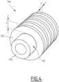
- each tube 740 comprises a tube body 742, having an outer surface 743 and defining a central passageway for the flow to be heated, and a plurality of external annular fins 745 extending radially from the tube body outer surface 743.
- the tube body outer surface 743 is preferably smooth.
- the outer surface may comprise corrugations in addition to the fins.
- the tube body 742 may comprise internal corrugations on its inner surface.
- the tube body 742 is preferably made of metal, for example of stainless steel.
- the fins 745 may be worked in the mass of the tube body 742 or attached to the outer surface 743, for example by welding.
- the fins 745 are substantially parallel to each other and arranged at predetermined intervals p (fin pitch p) to form passageways in which the gas flow circulating between the gas inlet 424, 444 and the gas outlet 426, 446 is to flow.
- the fins 745 are arranged along the tube body 742 at a constant fin pitch p, for example comprised between 2.5 mm and 10 mm. Alternatively, the fin pitch p is not constant. As shown on Figure 4 , the fin pitch p is represented by the center-to-center distance in the thickness direction of the two adjacent fins 745.
- the fins 745 have an annular plate shape, for example an annular flat plate shape, and define a fin height h extending radially from the tube body outer surface 743, the fin height h being comprised between 2 mm and 20mm.
- Such an arrangement allows the anodic gas flow 18 and the cathodic gas flow 20 coming from the fuel cell unit 30 to exchange heat with the incoming fuel and incoming air in cross current way, enhancing the heat transfer while requesting a smaller heat exchange area compared to a shell and tube type heat exchanger.
- the flow circulating in the tube bundles 74 of the first heat exchanger 42 is pre-heated by the anodic gas flow 18 coming from the fuel cell unit 30.
- the oxygen-rich gas flow 16 circulating in the tube bundles 74 of the second heat exchanger 44 is pre-heated by the cathodic gas flow 20 coming from the fuel cell unit 30.
- the fins have a non-flat shape.
- the fins have structured surfaces.
- the first heat exchanger 42 further comprised a water gas shift reactor 45 arranged in the circulation pipe 422.
- the water gas shift reactor 45 is configured to produce hydrogen from carbon monoxide present in the anodic gas flow 18.
- Water gas shift reactors are known to a person skilled in the art and will therefore not be discussed here in further detail.
- the first heat exchanger 42 and/or the second heat exchanger 44 comprise a deported tube bundle 75 connected to the tube bundles 74 of the other heat exchanger.
- a deported tube bundle 75 for conveying the oxygen-rich gas flow 16 is arranged in the circulation pipe 422 of the first heat exchanger 42 below the water gas shift reactor 45. Part of the oxygen-rich gas flow 16 is thus pre-heated by the anodic gas flow 18. Maximum heat can thus be recovered from the anodic gas flow 18 in the first heat exchanger 42 to preheat the flow circulating in the deported tube bundle 75 and to cool the anodic gas flow 18 so that it reaches desired temperature level before it is fed into the water gas shift reactor 45.
- the pretreatment unit 28 further comprises a supplemental furnace 46 for preheating the fuel gas flow 14 before its introduction in the first heat exchanger 42.
- the supplemental furnace 46 comprises a burner 80 along with a third heat exchanger system 82.
- the supplemental furnace 46 is connected to a fuel gas source (not shown) so that fuel gas 83 is injected into the burner 80 in order to be burned therein.
- the supplemental furnace 46 is connected to the carbon capture unit 34 so that a portion of a carbon dioxide recovered by the carbon capture unit 34 is reinjected in the burner 80.
- the second heat exchanger system 44 further comprises an outlet 84 connected to the burner 80 so that a portion 840 of the cathodic flow 20 circulating in the circulation pipe 442 is injected into the burner 80 and burned therein.
- the storage unit 22 is connected to the third heat exchanger system 82 located in the furnace 46 so that the fuel gas flow 14 is heated by the heat generated by the combustion inside the burner 80, in order to form a pre-heated fuel gas flow 35.
- the furnace 80 thus comprises an outlet 88 for recovering the pre-heated fuel gas flow 35.
- the outlet 88 of the furnace 80 is connected to the tube bundle system of the first heat exchanger system 42 so that the pre-heated fuel gas flow 35 is mixed with the recycled flow 38 coming from the carbon capture unit 34.
- the third heat exchanger 80 comprises a plurality of tube bundles 74 arranged at different elevation levels within the furnace 46.
- the pretreatment unit 28 further comprises, between the supplemental furnace 80 and the first heat exchanger system 42, a desulfurization unit 90 and a pre-reforming unit 92.
- the desulfurization unit 90 is intended for absorbing any sulfur present in the fuel gas flow 14, in order to prevent the downstream poisoning of the fuel cell unit 30. Desulfurization units are known to a person skilled in the art and will therefore not be discussed here in further detail.
- the pre-reforming unit 92 is intended for forming, from the desulfurized flow, a flow consisting of hydrogen, carbon monoxide, water and a portion of the unreacted initial fuel.
- the pre-reforming unit 92 converts hydrocarbons heavier than methane such as ethane, propane, butane and pentane present in the fuel gas flow 14 in order to prevent carbon deposition (or coking) within the fuel cell unit 30.
- the pre-reforming modules are known to a person skilled in the art and will therefore not be discussed here in further detail.
- a first tube bundle 74 of the third heat exchanger is connected upstream the desulfurization unit 90.
- An outlet of the desulfurization unit 57 is connected to a second tube bundle, which is connected to the pre-reforming unit 92.
- the pre-reforming unit 92 is connected to a third tube bundle of the third heat exchanger 82.
- the second tube bundle 74 is arranged within the enclosure 420 of the first heat exchanger system 42, in proximity of a tube bundle 74 in which the recycled flow 38 is circulating. Such arrangement further improves the pre-heating of the recycled flow.
- the pretreatment unit 28 may also comprise additional modules intended for removing other pollutants or impurities which would be present in the fuel gas flow 14, such as e.g. mercury. Such modules are known to a person skilled in the art who will know how to integrate same into the installation according to the invention without modifying the operation described herein.
- the fuel cell unit 30 is a solid oxide fuel cell unit and comprises at least one anode system 104 and at least one cathode system 106, separated from one another by at least one electrolyte, in particular a solid electrolyte.
- an anode system (or cathode system) comprises at least one anode (at least one cathode, respectively).
- An anode system (or cathode system) can thus comprise one anode (cathode respectively) or a plurality of anodes (cathodes respectively) associated with each other.
- the fuel cell unit 30 comprises an inlet 108 for introducing the heated fuel flow 50.
- the inlet 108 is intended for bringing the heated fuel flow 50 into contact with the anode system 104.
- the fuel cell unit 30 further includes an inlet 110 for introducing the heated oxygen-rich gas flow 52.
- the inlet 110 is intended for bringing the heated oxygen-rich gas flow 52 into contact with the cathode system 106.
- the fuel cell unit 30 further includes a first outlet 112 for recovering the anodic gas flow 18, coming from the operation of the fuel cell unit 30 and recovered at the anode system 104.
- the fuel cell unit 30 further includes a second outlet 114 for recovering the cathodic gas flow 20, coming from the operation of the fuel cell unit 30 and recovered at the cathode system 106.
- the outlets 112, 114 for recovering the anodic and cathodic gas flow 18, 20 are respectively connected upstream to the gas inlets 424, 444 of the first and second heat exchanger systems 42, 44 of the installation 10.
- the anodic and cathodic gas flow 18, 20 emerge from the fuel cell unit 30 at the outlets 112, 114, before entering the first and second heat exchanger systems 42, 44.
- the first outlet 112 emerges at the bottom of the circulation pipe 422 of the first heat exchanger 42 so that the anodic gas flow 18 circulates within the enclosure 422 from bottom to top in crossflow through and around the or each tube bundle 74.
- the anodic gas flow 18 is cooled therein by heat exchange with the tube bundles 74 extending within the same enclosure 420, in order to form a cooled anodic flow 180.
- the second outlet 114 emerges at the bottom of the circulation pipe 442 of the second heat exchanger 44, so that the cathodic gas flow 20 circulates from bottom to top in crossflow through and around the or each tube bundle 74.
- the cathodic gas flow 20 is cooled therein by heat exchange with the tube bundles 74 extending within the same enclosure 440, in order to form a cooled cathodic flow 200.
- Such embodiment is advantageous in that it can be used to heat the incoming flows before their introduction into the fuel cell unit 30, by heat integration, without requiring external energy input.
- the outlet 426 of the first heat exchanger system 42 is connected to the carbon capture unit 34.
- Such embodiment is advantageous in that same makes it possible both to heat the incoming fuel flow, which is a mixture of the recycled flow 38 and of the pre-heated fuel gas flow 35, before the introduction thereof into the fuel cell unit 30, and to cool the anodic gas flow 18, before the treatment thereof in the carbon capture unit 34, by heat integration without requiring external energy input.
- a post-treatment unit (not shown) is arranged between the first heat exchanger system 42 and the carbon capture unit 34.
- the post-treatment unit is intended to extract by condensation the excess water from the cooled anodic gas flow 180 and to convert into hydrogen and carbon dioxide at least a portion of the carbon monoxide present in the anodic gas flow 180. The conversion can then be used for increasing the concentration of carbon dioxide in the anodic gas flow 180 in order to facilitate the capture thereof in the carbon capture unit 34.
- the carbon capture unit 34 is intended for recovering at least a portion of the carbon dioxide present in the cooled anodic gas flow 180 in the form of a recycled carbon-dioxide depleted flow, which corresponds to the recycled flow 38.
- the carbon capture unit 34 typically comprises an inlet 340 for introducing the cooled anodic flow 180 and an outlet 342 for recovering the recycled flow 124.
- the outlet 118 for recovering the recycled flow 38 is connected to the pretreatment unit 28, in particular to the tube bundle system of the first heat exchanger 42 so that the carbon dioxide-depleted flow 38 is pre-heated in the first heat exchanger 42
- the heated fuel feed flow 50 entering the fuel cell system 30 consists of a mixture of the pre-heated fuel feed flow 35 coming from the furnace 46 and the carbon dioxide-depleted flow 38.
- the installation 10 further comprises a closed heat exchange circuit 134 for recovering the heat generated in one or a plurality of parts of the installation 10 in order to be transferred to another portion of the installation 10 so as to use same.
- the closed heat exchange circuit 134 is intended for supplying a portion of the heat required for the preheating in the first and second heat exchanger systems 42, 44.
- the closed circuit 134 is intended for making flow a heat-transfer fluid 136.
- the heat-transfer fluid may consist of pressurized liquid water, or further of a heat-transfer oil.
- the closed circuit 134 allows the recovery of residual heat, which may be used to heat water or oil, which further may be utilized in the carbon capture unit 34.
- the operation of the closed heat exchange circuit 134 requires a certain number of additional equipment (not shown, such as one or a plurality of expansion tanks, pumps, valve systems, etc). Such necessary equipment are well known to a person skilled in the art and will therefore not be described further hereinafter in the description.
- the method according to the invention comprises first of all supplying at least one fuel gas flow 14, coming from the storage unit 22 (or from a gas pipe network), and at least one oxygen-rich gas flow 16, coming from the pump and compressor system 24 (or from another storage system).
- the fuel gas flow 14 is first introduced into the pretreatment unit 28 in order to be heated and pre-treated.
- the fuel gas flow 14 is introduced into the supplemental furnace 46 and heated for the first time.
- the fuel gas flow 14 has a temperature ranging from 0°C to 50°C, more preferentially from 10°C to 30°C.
- the fuel gas flow 14 is heated in the third heat exchanger 82 to a temperature ranging from 400°C to 800°C, preferentially ranging from 600°C to 750°C.
- the fuel gas flow 14 also undergoes a preliminary desulfurization step so as to form a desulfurized fuel flow.
- the presence of sulfur in the fuel gas flow 14 is likely to lead to premature wear of the installation, in particular by poisoning the fuel cell unit 30.
- a desulfurization step may then be necessary to significantly reduce the concentration of sulfur in the fuel gas flow 14, preferentially to completely remove the sulfur present.
- the desulfurization step is carried out by introducing the preheated fuel gas flow 14 into the desulfurization unit 90.
- the desulfurized flow has a concentration of sulfur smaller than or equal to 1 ppm, more preferentially smaller than or equal to 0.1 ppm.
- the desulfurized flow may also undergo, within the pretreatment unit 28, a preliminary prereforming step.
- hydrocarbon compounds used as fuels are likely to fragment by thermal cracking, thus leading to the unwanted formation of deposits in the installation.
- a preliminary pre-reforming step makes it possible to prevent the thermal cracking phenomenon by converting the desulfurized flow into a flow consisting of dihydrogen H 2 , carbon monoxide CO, carbon dioxide, water and part of the methane present in the unreacted initial fuel gas. Such conversion is performed e.g. in contact with a catalyst such as nickel.
- the pre-reforming step is performed by making the desulfurized flow go through the pre-reforming unit 92.
- the flow recovered at the outlet of the pre-reforming unit 92 is then further pre-heated in the third heat exchanger system 82 to form a pre-heated fuel feed flow 35.
- the pre-heated fuel feed flow 35 is sent to the first heat exchanger system 42, where it is mixed with the recycled flow 38 recovered at the outlet 342 of the carbon capture unit 34 toward the pretreatment unit 28 in order to form a mixed fuel feed flow.
- Said mixed fuel feed flow circulates within the tube bundle system of the first heat exchanger system 42 and is further heated therein to form the heated fuel feed flow 50.
- the heated fuel feed flow 50 is then sent to the fuel cell unit 30, more precisely to the anode system 104.
- the heated fuel feed flow 50 typically has a molar concentration of dihydrogen H 2 ranging from 20% to 50%, preferentially from 30% to 40%.
- the heated fuel feed flow 50 typically has a molar concentration of carbon monoxide CO ranging from 0% to 15%, preferentially from 0% to 10%.
- the proportion in the flow of unreacted initial fuel is smaller than 50% (of the molar composition), more preferentially smaller than 30%, in particular between 20% and 30%.
- the oxygen-rich gas flow 16 is heated by flowing through the second heat exchanger system 44.
- At least part of the oxygen-rich gas flow 16 is conveyed in the deported tube bundle 75, so that it is pre-heated in the first heat exchanger system 42.
- the oxygen-rich gas flow 16 is heated in the second heat exchanger system 44 to a temperature ranging from 500°C to 800°C, preferentially ranging from 600°C to 700°C.
- the heated oxygen-rich gas flow 52 is then introduced into the fuel cell unit 30, more precisely into the cathode system 106.
- the fuel cell unit 30 fed continuously with the heated fuel flow 50 and the heated oxygen-rich gas flow 52, is then put into operation.
- the heated fuel flow 50 is introduced into the fuel cell unit 30, at the inlet 108.
- the heated fuel flow 50 is injected at the anode system 104.
- the heated oxygen-rich gas flow 52 is introduced at the inlet 110 of the fuel cell unit 30.
- the heated oxygen-rich gas flow 16 is injected into the cathode system 106.
- the heated fuel flow 50 undergoes a first reforming step during which all the initial fuel is converted into a synthesis gas consisting of hydrogen H 2 and carbon monoxide CO.
- the hydrogen H 2 In contact with the anode system 104, the hydrogen H 2 dissociates into protons H + and electrons.
- the electrons thus released accumulate at the anode system 104 and are transferred to the cathode system 106 of the unit 30 by means of an external circuit, the displacement of the electrons from the anode system 104 to the cathode system 106 generating the electric current.
- the electrons conveyed are fixed by the oxygen O2 present in the heated oxygen-rich gas flow 52, resulting in the transformation of the oxygen O 2 molecules into oxygen ions O 2- .
- the oxygen ions O 2- thus formed then flow through the electrolyte and cross over to the side of the anode system 104 where same react with the previously generated H + protons so as to form water H 2 O and with carbon monoxide CO so as to form carbon dioxide CO 2 .
- the anodic gas flow 18 and the cathodic gas flow 20 are then recovered at the outlet of the fuel cell unit 30.
- the flow 20 has a reduced concentration of oxygen relative to the initial oxygen-rich gas flow 16.
- the cathodic gas flow 38 has a concentration of oxygen smaller than or equal to 20% molar, preferentially from 5% molar to 15% molar.
- the cathodic gas flow 20 is then conveyed to the collecting installation 26, by first circulating within the enclosure 440 of the second heat exchanger system 44.
- the cathodic gas flow 20 is cooled by flowing through the second heat exchanger systems 44.
- the cathodic gas flow 20 is first introduced into the second heat exchanger at the inlet 444 and flows in the circulation pipe 442 from bottom to top in crossflow around the tubes 740 of the or each tube bundle 74 extending within the circulation pipe 442.
- Heat exchanges take place between the oxygen-rich gas flow 16 flowing inside the tubes 740 of the second heat exchanger system 44 and the cathodic gas flow 20, so that the oxygen-rich gas flow 16 is pre-heated and the cathodic gas flow 20 is cooled, forming a cooled cathodic gas flow 200.
- the cooled cathodic flow 200, recovered at the outlet 446 of the second heat exchanger system 44, is then conveyed to the collecting installation 26 for post-treatment or for discharging directly into the atmosphere.
- the cathodic gas flow 20 is cooled in the second heat exchanger system 44 to a temperature ranging from 50°C to 250°C, preferentially ranging from 80°C to 150°C.
- the flow 18 consists of a mixture of carbon dioxide CO 2 , water H 2 O resulting from the operation of the fuel cell unit and further of carbon monoxide CO and hydrogen H2 which has not reacted.
- At least 30% by volume of the initial synthesis gas is recovered in the anodic gas flow, more preferentially from 30% to 50% by volume.
- the anodic gas flow 18 has a concentration of carbon dioxide greater than 10% by volume, more preferentially from 10% to 40% by volume, typically from 20% to 40% by volume.
- the anodic gas flow 18 is free of sulfur.
- the anodic gas flow 18, recovered at the outlet of the fuel cell unit 30, typically has a temperature greater than 500°C, preferentially ranging from 750°C to 850°C.
- the entire anodic gas flow 18, recovered at the outlet 112 of the fuel cell unit 30, is then introduced into the enclosure 420 of the first heat exchanger system 42 in order to be cooled therein by flowing within the circulation pipe 422.
- the anodic gas flow 36 flows in the circulation pipe 442 from bottom to top in crossflow around the tubes 740 of the or each tube bundle 74 in the first heat exchanger system 42 and is cooled by heat exchange with the preheated fuel flow 35 and the recycled flow 38 flowing in the tube bundles 74.
- a cooled anodic flow 180 is thus obtained at the outlet 426 of the first heat exchanger 42.
- the anodic gas flow 18 is cooled in the first heat exchanger system 42 to a temperature ranging from 50°C to 300°C, preferentially ranging from 75°C to 150°C.
- Such embodiment is advantageous in that same can be used for heating the preheated fuel flow 35 and the recycled flow 38, before being introduced into the fuel cell unit 30, and to pre-cool the anodic gas flow 36, by heat integration without requiring external energy input.
- the cooled anodic flow 180 is then preferably introduced into the post-treatment unit when it is present.
- the cooled anodic flow 180 is then introduced into the carbon capture unit 34 in order to form the recycled flow 38.
- the recycled carbon dioxide-depleted flow 38 typically comprises from 10% to 60% by volume of carbon dioxide CO2, preferentially from 20% to 50% by volume.
- the recycled flow 38 recovered at the outlet of the carbon capture unit 34 is then injected into the tube bundle system at the top of the first heat exchanger system 42 and is pre-heated therein.
- the recycled flow 38 is then mixed with the preheated fuel feed flow 35 in order to form the heated fuel feed flow 50.
- the recycled flow 38 represents at least 30% by volume of the heated fuel feed flow 50, more preferentially from 40% to 85% by volume, even more preferentially from 45% to 80% by volume.
- the preheated fuel feed flow 35 represents at least 70% by volume of the fuel feed flow, more preferentially from 15% to 60% by volume, even more preferentially from 20% to 55% by volume.
- Fuel gas is further injected into the furnace 46 in order to be burned therein.
- a portion of the carbon dioxide flow recovered from the carbon capture unit 34 is further injected into the furnace 46, in particular into the burner 80, in order to be burned with the fuel gas.
- a portion 840 of the oxygen-depleted cathodic flow 20 is also injected into the furnace 46, in particular into the burner 80, in order to be burned therein.
- the other portion of the oxygen-depleted flow 20 is then conveyed to the installation 26 after flowing through the circulation pipe 442.
- the portion 840 of the oxygen-depleted cathodic flow 20 injected into the furnace 46 is adjusted in order to maintain excess oxygen in the burner 80, advantageously so that oxygen is maintained to be in excess of 2% by volume.
- the installation 10 and the method according to the invention can thus be used for producing an electric current by means of a solid oxide fuel cell unit 30 while reducing the energy required.
- the installation 10 and the method according to the invention make it possible to significantly reduce the energy requirement associated with the preheating of the flows, which feed the fuel cell unit 30, by proposing to re-use a significant portion of the heat emitted during the operation of the fuel cell unit 30. A portion of the heat energy dispersed by the fuel cell unit 30 is thus recovered, thereby increasing the overall efficiency of the system.
- the vertically arranged installation of the first and second heat exchanger systems 42, 44 allows an efficient utilization of the heat and the reduction of the temperature of the flows produced by the fuel cell unit 30 as low as around 1 00°C, without requiring additional cooling systems.
- Such smaller heat transfer area allows to arrange the exchangers in a modular stacked and enclosed structure, eliminating the need of shell for individual exchanger, thereby making it possible to operate at near atmospheric pressure without requiring high thickness otherwise necessary for shell and tube type of exchangers arrangement.
- the stacking of the heat exchanger systems takes the benefit of clean exhaust gas free of sulfur, thereby avoiding any sulfur condensation leading to issues like acidic corrosion, and eliminates the need of connecting pipelines between exchanger, thus avoiding any potential for gas/air leak and avoiding heat losses.
- the method and the installation according to the invention lead therefore to saving equipment and energy consumption in the overall chain (electricity production, capture) and reduce the overall plot plan area required to accommodate the entire process.
Landscapes
- Engineering & Computer Science (AREA)
- Chemical & Material Sciences (AREA)
- Life Sciences & Earth Sciences (AREA)
- Sustainable Development (AREA)
- Manufacturing & Machinery (AREA)
- Sustainable Energy (AREA)
- Chemical Kinetics & Catalysis (AREA)
- Electrochemistry (AREA)
- General Chemical & Material Sciences (AREA)
- Combustion & Propulsion (AREA)
- Fuel Cell (AREA)
Priority Applications (3)
| Application Number | Priority Date | Filing Date | Title |
|---|---|---|---|
| EP23305339.6A EP4432405A1 (de) | 2023-03-13 | 2023-03-13 | Brennstoffzellenanlage mit einem festoxidbrennstoffzellensystem und verfahren zum betrieb davon |
| AU2024234821A AU2024234821A1 (en) | 2023-03-13 | 2024-03-12 | Fuel cell installation comprising a solid oxide fuel cell system and method of operating the same |
| PCT/EP2024/056520 WO2024189008A1 (en) | 2023-03-13 | 2024-03-12 | Fuel cell installation comprising a solid oxide fuel cell system and method of operating the same |
Applications Claiming Priority (1)
| Application Number | Priority Date | Filing Date | Title |
|---|---|---|---|
| EP23305339.6A EP4432405A1 (de) | 2023-03-13 | 2023-03-13 | Brennstoffzellenanlage mit einem festoxidbrennstoffzellensystem und verfahren zum betrieb davon |
Publications (1)
| Publication Number | Publication Date |
|---|---|
| EP4432405A1 true EP4432405A1 (de) | 2024-09-18 |
Family
ID=85778706
Family Applications (1)
| Application Number | Title | Priority Date | Filing Date |
|---|---|---|---|
| EP23305339.6A Pending EP4432405A1 (de) | 2023-03-13 | 2023-03-13 | Brennstoffzellenanlage mit einem festoxidbrennstoffzellensystem und verfahren zum betrieb davon |
Country Status (3)
| Country | Link |
|---|---|
| EP (1) | EP4432405A1 (de) |
| AU (1) | AU2024234821A1 (de) |
| WO (1) | WO2024189008A1 (de) |
Citations (3)
| Publication number | Priority date | Publication date | Assignee | Title |
|---|---|---|---|---|
| US20110053027A1 (en) * | 2009-09-02 | 2011-03-03 | Bloom Energy Corporation | Multi-Stream Heat Exchanger for a Fuel Cell System |
| US20140352931A1 (en) * | 2013-05-31 | 2014-12-04 | Steve Turner | Corrosion Resistant Air Preheater with Lined Tubes |
| CN115332565A (zh) * | 2022-09-05 | 2022-11-11 | 中海石油气电集团有限责任公司 | 一种sofc高效换热系统 |
-
2023
- 2023-03-13 EP EP23305339.6A patent/EP4432405A1/de active Pending
-
2024
- 2024-03-12 WO PCT/EP2024/056520 patent/WO2024189008A1/en not_active Ceased
- 2024-03-12 AU AU2024234821A patent/AU2024234821A1/en active Pending
Patent Citations (3)
| Publication number | Priority date | Publication date | Assignee | Title |
|---|---|---|---|---|
| US20110053027A1 (en) * | 2009-09-02 | 2011-03-03 | Bloom Energy Corporation | Multi-Stream Heat Exchanger for a Fuel Cell System |
| US20140352931A1 (en) * | 2013-05-31 | 2014-12-04 | Steve Turner | Corrosion Resistant Air Preheater with Lined Tubes |
| CN115332565A (zh) * | 2022-09-05 | 2022-11-11 | 中海石油气电集团有限责任公司 | 一种sofc高效换热系统 |
Also Published As
| Publication number | Publication date |
|---|---|
| AU2024234821A1 (en) | 2025-10-02 |
| WO2024189008A1 (en) | 2024-09-19 |
Similar Documents
| Publication | Publication Date | Title |
|---|---|---|
| CN105264701B (zh) | 使用燃料电池的综合发电和碳捕集 | |
| US9077007B2 (en) | Integrated power generation and chemical production using fuel cells | |
| US11691874B2 (en) | Apparatuses and methods for hydrogen production | |
| CN119365672A (zh) | 用于在燃气涡轮中产生动力的工艺 | |
| US12162772B2 (en) | System for offshore production of fuel | |
| EP4432405A1 (de) | Brennstoffzellenanlage mit einem festoxidbrennstoffzellensystem und verfahren zum betrieb davon | |
| US20170214072A1 (en) | Apparatus and method of operation for reformer and fuel cell system | |
| US20230022303A1 (en) | Method Of Operating A Fuel Cell System With Carbon Dioxide Recovery And Associated Installation | |
| AU2007260574A1 (en) | Improvements in the utilisation of methane | |
| JP7854043B2 (ja) | リアクター及びアンモニアを分解する装置と方法 | |
| US12370522B2 (en) | Oxygen transport reactors for co-generating ammonia and power | |
| WO2025215366A1 (en) | Process and plant | |
| KR20260014348A (ko) | 개질기 | |
| CN120359345A (zh) | 使用电解过程产生的富集空气来燃烧尾气 | |
| CN107534170A (zh) | 用于多个燃料电池堆的壳体 | |
| KR20160101076A (ko) | 고체 산화물 연료 전지 시스템을 위한 가스 회로 및 고체 산화물 연료 전지 시스템 |
Legal Events
| Date | Code | Title | Description |
|---|---|---|---|
| PUAI | Public reference made under article 153(3) epc to a published international application that has entered the european phase |
Free format text: ORIGINAL CODE: 0009012 |
|
| STAA | Information on the status of an ep patent application or granted ep patent |
Free format text: STATUS: THE APPLICATION HAS BEEN PUBLISHED |
|
| AK | Designated contracting states |
Kind code of ref document: A1 Designated state(s): AL AT BE BG CH CY CZ DE DK EE ES FI FR GB GR HR HU IE IS IT LI LT LU LV MC ME MK MT NL NO PL PT RO RS SE SI SK SM TR |
|
| STAA | Information on the status of an ep patent application or granted ep patent |
Free format text: STATUS: REQUEST FOR EXAMINATION WAS MADE |
|
| 17P | Request for examination filed |
Effective date: 20250128 |
|
| P01 | Opt-out of the competence of the unified patent court (upc) registered |
Free format text: CASE NUMBER: APP_19829/2025 Effective date: 20250424 |