EP4432375A1 - Battery cell, battery and electric device - Google Patents
Battery cell, battery and electric device Download PDFInfo
- Publication number
- EP4432375A1 EP4432375A1 EP23880895.0A EP23880895A EP4432375A1 EP 4432375 A1 EP4432375 A1 EP 4432375A1 EP 23880895 A EP23880895 A EP 23880895A EP 4432375 A1 EP4432375 A1 EP 4432375A1
- Authority
- EP
- European Patent Office
- Prior art keywords
- size
- tab portion
- battery
- conductive structure
- zone
- Prior art date
- Legal status (The legal status is an assumption and is not a legal conclusion. Google has not performed a legal analysis and makes no representation as to the accuracy of the status listed.)
- Pending
Links
Images




Classifications
-
- H—ELECTRICITY
- H01—ELECTRIC ELEMENTS
- H01M—PROCESSES OR MEANS, e.g. BATTERIES, FOR THE DIRECT CONVERSION OF CHEMICAL ENERGY INTO ELECTRICAL ENERGY
- H01M50/00—Constructional details or processes of manufacture of the non-active parts of electrochemical cells other than fuel cells, e.g. hybrid cells
- H01M50/20—Mountings; Secondary casings or frames; Racks, modules or packs; Suspension devices; Shock absorbers; Transport or carrying devices; Holders
- H01M50/204—Racks, modules or packs for multiple batteries or multiple cells
- H01M50/207—Racks, modules or packs for multiple batteries or multiple cells characterised by their shape
- H01M50/209—Racks, modules or packs for multiple batteries or multiple cells characterised by their shape adapted for prismatic or rectangular cells
-
- H—ELECTRICITY
- H01—ELECTRIC ELEMENTS
- H01M—PROCESSES OR MEANS, e.g. BATTERIES, FOR THE DIRECT CONVERSION OF CHEMICAL ENERGY INTO ELECTRICAL ENERGY
- H01M50/00—Constructional details or processes of manufacture of the non-active parts of electrochemical cells other than fuel cells, e.g. hybrid cells
- H01M50/50—Current conducting connections for cells or batteries
- H01M50/528—Fixed electrical connections, i.e. not intended for disconnection
-
- H—ELECTRICITY
- H01—ELECTRIC ELEMENTS
- H01M—PROCESSES OR MEANS, e.g. BATTERIES, FOR THE DIRECT CONVERSION OF CHEMICAL ENERGY INTO ELECTRICAL ENERGY
- H01M50/00—Constructional details or processes of manufacture of the non-active parts of electrochemical cells other than fuel cells, e.g. hybrid cells
- H01M50/50—Current conducting connections for cells or batteries
- H01M50/531—Electrode connections inside a battery casing
- H01M50/538—Connection of several leads or tabs of wound or folded electrode stacks
-
- H—ELECTRICITY
- H01—ELECTRIC ELEMENTS
- H01M—PROCESSES OR MEANS, e.g. BATTERIES, FOR THE DIRECT CONVERSION OF CHEMICAL ENERGY INTO ELECTRICAL ENERGY
- H01M50/00—Constructional details or processes of manufacture of the non-active parts of electrochemical cells other than fuel cells, e.g. hybrid cells
- H01M50/50—Current conducting connections for cells or batteries
- H01M50/572—Means for preventing undesired use or discharge
- H01M50/574—Devices or arrangements for the interruption of current
- H01M50/583—Devices or arrangements for the interruption of current in response to current, e.g. fuses
-
- H—ELECTRICITY
- H01—ELECTRIC ELEMENTS
- H01M—PROCESSES OR MEANS, e.g. BATTERIES, FOR THE DIRECT CONVERSION OF CHEMICAL ENERGY INTO ELECTRICAL ENERGY
- H01M2200/00—Safety devices for primary or secondary batteries
- H01M2200/10—Temperature sensitive devices
- H01M2200/103—Fuse
-
- H—ELECTRICITY
- H01—ELECTRIC ELEMENTS
- H01M—PROCESSES OR MEANS, e.g. BATTERIES, FOR THE DIRECT CONVERSION OF CHEMICAL ENERGY INTO ELECTRICAL ENERGY
- H01M2220/00—Batteries for particular applications
- H01M2220/20—Batteries in motive systems, e.g. vehicle, ship, plane
-
- H—ELECTRICITY
- H01—ELECTRIC ELEMENTS
- H01M—PROCESSES OR MEANS, e.g. BATTERIES, FOR THE DIRECT CONVERSION OF CHEMICAL ENERGY INTO ELECTRICAL ENERGY
- H01M50/00—Constructional details or processes of manufacture of the non-active parts of electrochemical cells other than fuel cells, e.g. hybrid cells
- H01M50/50—Current conducting connections for cells or batteries
- H01M50/531—Electrode connections inside a battery casing
- H01M50/536—Electrode connections inside a battery casing characterised by the method of fixing the leads to the electrodes, e.g. by welding
-
- Y—GENERAL TAGGING OF NEW TECHNOLOGICAL DEVELOPMENTS; GENERAL TAGGING OF CROSS-SECTIONAL TECHNOLOGIES SPANNING OVER SEVERAL SECTIONS OF THE IPC; TECHNICAL SUBJECTS COVERED BY FORMER USPC CROSS-REFERENCE ART COLLECTIONS [XRACs] AND DIGESTS
- Y02—TECHNOLOGIES OR APPLICATIONS FOR MITIGATION OR ADAPTATION AGAINST CLIMATE CHANGE
- Y02E—REDUCTION OF GREENHOUSE GAS [GHG] EMISSIONS, RELATED TO ENERGY GENERATION, TRANSMISSION OR DISTRIBUTION
- Y02E60/00—Enabling technologies; Technologies with a potential or indirect contribution to GHG emissions mitigation
- Y02E60/10—Energy storage using batteries
Definitions
- This application relates to the field of battery technologies, and in particular, to a battery cell, a battery, and an electric device.
- thermal runaway inside batteries In the development of battery technology, in addition to improving the performance of the battery, the occurrence of thermal runaway inside batteries is also a non-negligible issue. If thermal runaway occurs inside a battery, the battery becomes unusable. Therefore, how the probability of thermal runaway inside batteries is reduced is an urgent problem to be resolved in battery technology.
- embodiments of this application provide a battery cell, a battery, and an electric device, to reduce the probability of thermal runaway in batteries.
- a battery cell including an electrode assembly including a body portion and a lead-out portion that are disposed in a first direction, the body portion being electrically connected to an electrode terminal via the lead-out portion.
- the lead-out portion includes a tab portion and a conductive structure. A first end of the conductive structure is welded to the tab portion to form a welded zone, a second end of the conductive structure is connected to the electrode terminal, and the conductive structure extends in a direction leaving the body portion.
- a melting zone is provided between the welded zone and the body portion.
- the electrode assembly includes the body portion and the lead-out portion. Further, the lead-out portion includes the tab portion and the conductive structure.
- the conductive structure is welded to the tab portion to form the welded zone, and the melting zone is provided between the welded zone and the body portion. With the melting zone provided between the body portion and the welded zone and the welded zone formed by welding the tab portion to the conductive structure, the melting zone serves as a fuse in the battery cell and therefore can blow when a large current passes through, preventing risks such as lithium precipitation and excessive heat generation caused by the passage of the large current in the electrode assembly, thus reducing the risk of thermal runaway in the battery.
- the conductive structure is directly electrically connected to the electrode terminal without using another component such as an adapter sheet, thereby increasing the weight energy density and production efficiency of the battery and reducing production costs.
- a size of the melting zone is larger than a size of the conductive structure, the second direction being perpendicular to the first direction and parallel to the tab portion.
- the size of the melting zone in the second direction is larger than the size of the conductive structure; in other words, the melting zone exceeds the conductive structure in the second direction.
- a size of the melting zone is not smaller than half the size of the body portion.
- making the size of the melting zone in the second direction not smaller than half the size of the body portion can increase the current flow area of the melting zone and reduce heat generation.
- the body portion includes a straight portion and a bent portion.
- the body portion of the electrode assembly when the electrode assembly is of a wound type, that is, when multiple electrode plates are wound to form the electrode assembly, the body portion of the electrode assembly includes the straight portion and the bent portion.
- the size of the melting zone is not larger than a size of the straight portion.
- the size of the melting zone in the second direction is made to be not larger than the size of the straight portion, that is, the melting zone does not need to maintain bent. This can reduce the production difficulty and is advantageous to wide-scale production.
- the electrode assembly includes multiple electrode plates, where the electrode plate includes a non-metal layer and a metal layer disposed on two sides of the non-metal layer, and the conductive structure is welded to the metal layer of the tab portion to form the welded zone.
- the electrode assembly includes multiple electrode plates.
- the electrode plate includes the non-metal layer and the metal layer, where the metal layer is disposed on two sides of the non-metal layer. Since the electrode plate is provided with the non-metal layer, the thickness of the metal layer can be reduced. As a result, burrs generated at a part of the metal layer punctured by a foreign matter are small, making it difficult to puncture the separator.
- the electrode plate including the non-metal layer and metal layer disposed on two sides of the non-metal layer can reduce the risk of short circuits of the battery caused by a foreign matter puncturing the metal layer.
- the electrode assembly includes multiple electrode plates, where the electrode plate includes a non-metal layer and a metal layer disposed on two sides of the non-metal layer, and the conductive structure is welded to the metal layer of the tab portion to form the welded zone.
- the electrode assembly includes multiple electrode plates.
- the electrode plate includes the non-metal layer and the metal layer, where the metal layer is disposed on two sides of the non-metal layer. Since the electrode plate is provided with the non-metal layer, the thickness of the metal layer can be reduced. As a result, burrs generated at a part of the metal layer punctured by a foreign matter are small, making it difficult to puncture the separator.
- the electrode plate including the non-metal layer and metal layer disposed on two sides of the non-metal layer can reduce the risk of short circuits of the battery caused by a foreign matter puncturing the metal layer.
- a size of the melting zone is smaller than a size of the conductive structure, the second direction being perpendicular to the first direction and parallel to the tab portion.
- the size of the melting zone in the second direction is smaller than the size of the conductive structure; in other words, the melting zone is recessed into the conductive structure in the second direction.
- a size of the melting zone is smaller than a size of the conductive structure, the third direction being perpendicular to the first direction and perpendicular to the tab portion.
- the size of the melting zone in the third direction is smaller than the size of the conductive structure; in other words, the tab portion is recessed into the conductive structure in the third direction.
- the melting zone is provided with a melting hole.
- providing the melting hole on the melting zone can further reduce the current flow capability of the melting zone, thereby further reducing the risk of thermal runaway in the battery.
- the battery cell further includes a separator, where the separator covers the melting hole.
- covering the melting hole with the separator can prevent burrs generated during preparation of the melting hole from puncturing the electrode plate, while such puncturing affects performance of the battery.
- the tab portion includes a first tab portion and a second tab portion, where the first tab portion is disposed between the body portion and the second tab portion, and in the second direction, a size of the first tab portion is larger than a size of the second tab portion.
- the size of the first tab portion is larger than the size of the second tab portion.
- the first tab portion connected to the body portion has a larger size in the second direction, which can increase the connection area between the body portion and the tab portion, thereby increasing the connection strength between the two.
- the second tab portion having a smaller size can reduce the space occupied by the entire tab portion in the battery while a stable connection between the tab portion and the body portion is ensured.
- the welded zone includes a first welded zone and a second welded zone, where the first welded zone is located on the first tab portion, the second welded zone is located on the second tab portion, and in the second direction, a size of the first welded zone is larger than a size of the second welded zone.
- the first welded zone is located on the first tab portion that has a larger size in the second direction, allowing for a larger welding area between the conductive structure and the first tab portion, thereby increasing the connection strength between the two.
- a first protective layer is provided at an end of the tab portion close to the body portion, where the first protective layer is disposed between the body portion and the melting zone.
- a first protective layer is provided at an outer surface of a part of the tab portion, where the part of the tab portion is not covered by the conductive structure and does not serve as the melting zone, and the first protective layer is disposed between the body portion and the melting zone.
- the first protective layer is disposed on a part of the tab portion that is neither covered by the active substance nor connected to the conductive structure and that does not serve as the melting zone.
- the stiffness of the first protective layer can be larger than the stiffness of the metal layer. This allows the first protective layer to have a larger stiffness so as to support the tab portion and limit deformation of the tab portion, thereby preventing the metal layer from rupturing, and improving the current flow capability of the electrode plate.
- a size of the first protective layer is 0.1 mm to 6 mm.
- the size of the first protective layer in the first direction directly affects the effects of the first protective layer in protecting the tab portion. If the size of the first protective layer is too small, the adhesion between the first protective layer and the tab portion is weak, making them prone to fall off, and the coverage area is small, leading to weak capability to inhibit deformation of the tab portion is weak. If the size of the first protective layer is too large, the connection area between the tab portion and the conductive structure is reduced, decreasing the current flow capability between the conductive structure and the electrode assembly.
- the first protective layer with the size in the first direction maintained within 0.1 mm to 6 mm can not only support the tab portion but also ensure good current flow capability between the conductive structure and the electrode assembly.
- a size of the first protective layer is 0.5 mm to 4 mm.
- keeping the size of the first protective layer in the first direction within 0.5 mm to 4 mm can provide support to the tab portion and reserve enough region for the melting zone.
- a size of the melting zone is 0.01 mm to 2 mm.
- the first protective layer is disposed on a part of the tab portion that is neither covered by the active substance nor connected to the conductive structure and that does not serve as the melting zone. If the size of the melting zone is too small, a part of the conductive structure may overlap with the first protective layer, resulting in tilt of the conductive structure and thus poor connection, thereby affecting the service life of the battery. Making the size of the melting zone in the first direction fall within 0.01 mm to 2 mm can ensure the normal service life of the battery.
- a size of the first protective layer is 0.05 mm to 1.5 mm.
- making the size of the melting zone in the first direction fall within 0.05 mm to 1.5 mm can further ensure the normal service life of the battery.
- a second protective layer is disposed on a surface of the welded zone away from the tab portion.
- the surface of the welded zone may become uneven. As a result, the separator may be punctured, posing a short circuit risk.
- the second protective layer provided on the surface of the welded zone the surface of the welded zone can be separated from the separator, preventing the separator from being punctured, thus further improving the safety performance of the battery.
- both the first protective layer and the second protective layer are made of an insulating material.
- the insulating material does not have the function of electrical connection.
- Both the first protective layer and the second protective layer being made of an insulating material can prevent the first protective layer and second protective layer from affecting a current flow path of the electrode plate in the electrode assembly, thus ensuring the safety of the electrical connection of the electrode plate.
- a battery including the battery cell according to any one of the embodiments of the first aspect.
- an electric device including the battery according to the second aspect, where the battery is configured to supply electric energy.
- the electrode assembly includes the body portion and the lead-out portion, and the lead-out portion includes the tab portion and the conductive structure.
- the first end of the conductive structure is welded to the tab portion to form the welded zone
- the melting zone is provided between the welded zone and the body portion
- another end of the conductive structure is directly connected to the electrode terminal.
- the melting zone can serve as a fuse and therefore can melt the tab portion when a large current passes through, preventing risks of lithium precipitation and excessive heat generation caused by the passage of the large current in the electrode assembly, thus reducing the risk of thermal runaway in the battery.
- the conductive structure is directly connected to the end cover without using another component such as an adapter sheet, thereby increasing the weight energy density and production efficiency of the battery and reducing production costs.
- the battery cell may include a lithium-ion secondary battery, a lithium-ion primary battery, a lithium-sulfur battery, a sodium-lithium-ion battery, a sodium-ion battery, a magnesium-ion battery, or the like.
- the battery cell may be cylindrical, flat, cuboid, or of other shapes. This is not limited in the embodiments of this application either.
- Battery cells are typically divided into three types by packaging method: cylindrical cell, prismatic cell, and pouch cell. This is not limited in the embodiments of this application either.
- the battery mentioned in the embodiments of this application is a single physical module that includes one or more battery cells for providing a higher voltage and capacity.
- the battery mentioned in this application may include a battery module, a battery pack, or the like.
- a battery typically includes a box configured to enclose one or more battery cells. The box can prevent liquids or other foreign matter from affecting charging or discharging of the battery cell.
- the battery cell may include an electrode assembly and an electrolyte.
- the electrode assembly includes a positive electrode plate, a negative electrode plate, and a separator.
- Working of the battery cell mainly relies on migration of metal ions between the positive electrode plate and the negative electrode plate.
- the positive electrode plate includes a positive electrode current collector and a positive electrode active substance layer.
- the positive electrode active substance layer is applied on a surface of the positive electrode current collector.
- the part of positive electrode current collector uncoated with the positive electrode active substance layer protrudes out of the part of positive electrode current collector coated with the positive electrode active substance layer and serves as a positive tab.
- a lithium-ion battery is used as an example, for which, the positive electrode current collector may be made of aluminum and the positive electrode active substance may be lithium cobaltate, lithium iron phosphate, ternary lithium, lithium manganate, or the like.
- the negative electrode plate includes a negative electrode current collector and a negative electrode active substance layer. The negative electrode active substance layer is applied on a surface of the negative electrode current collector. The part of negative electrode current collector uncoated with the negative electrode active substance layer protrudes out of the part of negative electrode current collector coated with the negative electrode active substance layer and serves as a negative tab.
- the negative electrode current collector may be made of copper, and the negative electrode active substance may be graphite, carbon, silicon, or the like.
- the separator may be made of polypropylene (polypropylene, PP), polyethylene (polyethylene, PE), or the like.
- the electrode assembly may be a wound structure or a laminated structure, but the embodiments of this application are not limited thereto.
- Electric vehicle batteries have been widely used in energy storage power supply systems such as hydroelectric power plants, thermal power plants, wind power plants, and solar power plants, and many other fields including electric transportation tools such as electric bicycles, electric motorcycles, and electric vehicles, military equipment, and aerospace. With continuous expansion of application fields of electric vehicle batteries, market demands for electric vehicle batteries are also expanding.
- performance parameters such as energy density, cycling performance, discharge capacity, and charge and discharge rate, as well as safety performance and production costs of batteries.
- an embodiment of this application provides an electrode assembly.
- the electrode assembly includes a body portion and a lead-out portion.
- the lead-out portion includes a tab portion and a conductive structure.
- a first end of the conductive structure is welded to the tab portion to form a welded zone, a melting zone is provided between the welded zone and the body portion, and another end of the conductive structure is directly connected to an electrode terminal.
- the melting zone can serve as a fuse and therefore can melt the tab portion when a large current passes through, preventing risks of lithium precipitation and excessive heat generation caused by the passage of the large current in the electrode assembly, thus reducing the risk of thermal runaway in the battery.
- the conductive structure is directly connected to the end cover without using another component such as an adapter sheet, thereby increasing the weight energy density and production efficiency of the battery and reducing production costs.
- the technical solutions described in the embodiments of this application are all applicable to various devices using batteries, such as mobile phones, portable devices, notebook computers, electric bicycles, electric toys, electric tools, electric vehicles, ships, and spacecraft.
- the spacecraft includes planes, rockets, space shuttles, spaceships, and the like.
- FIG. 1 is a schematic structural diagram of a vehicle according to an embodiment of this application.
- the vehicle 1 may be a fossil fuel vehicle, a natural-gas vehicle, or a new energy vehicle, where the new energy vehicle may be a battery electric vehicle, a hybrid electric vehicle, a range-extended vehicle, or the like.
- a motor 40, a controller 30, and a battery 10 may be provided inside the vehicle 1, where the controller 30 is configured to control the battery 10 to supply power to the motor 40.
- the battery 10 may be disposed at the bottom, front, or rear of the vehicle 1.
- the battery 10 may be configured to supply power to the vehicle 1.
- the battery 10 may be used as an operational power source for the vehicle 1 which is configured for a circuit system of the vehicle 1, for example, to satisfy power needs of start, navigation, and running of the vehicle 1.
- the battery 10 can be used not only as the operational power source for the vehicle 1, but also as a driving power source for the vehicle 1, replacing or partially replacing fossil fuel or natural gas to provide driving traction for the vehicle 1.
- the battery 10 may include a plurality of battery cells.
- FIG. 2 is a schematic structural exploded view of a battery 10 according to an embodiment of this application.
- the battery 10 may include a plurality of battery cells 20.
- the number of the battery cells 20 may be set to any numerical value.
- the multiple battery cells 20 may be connected in series, in parallel, or in series and parallel to achieve greater capacity or power. Because the number of battery cells 20 included in each battery 10 may be large, for ease of installation, the battery cells 20 may be arranged in groups, and each group of battery cells 20 forms a battery module.
- the number of battery cells 20 included in the battery module is not limited, and may be set according to requirements.
- a battery may include multiple battery modules. These battery modules may be connected in series, parallel, or series-parallel.
- the battery 10 may further include other structures.
- the battery 10 may also include a busbar that is used to implement electrical connection between the multiple battery cells 20, for example, in parallel, in series, or in hybrid connection.
- the busbar may enable the electrical connection between the battery cells 20 by connecting the electrode terminals of the battery cells 20.
- the busbar may be fixed to the electrode terminals of battery cells 20 by welding. Electrical energy of the plurality of battery cells 20 can be further drawn out of the box through a conductive mechanism.
- the conductive structure may also belong to the busbar.
- the battery 10 may further include a box 11 (or referred to as a cover), where the box 11 has a hollow structure inside, and the plurality of battery cells 20 are accommodated in the box 11.
- the box 11 may include two portions: an upper box body 111 and a lower box body 112.
- the upper box body 111 and the lower box body 112 are snap-fitted together. Shapes of the upper box body 111 and the lower box body 112 may be determined based on a shape of the plurality of combined battery cells 20, and at least one of the upper box body 111 and the lower box body 112 has an opening.
- one of the upper box body 111 and the lower box body 112 included in the box 11 is a hollow cuboid with an opening, and the other is plate shaped for covering the opening.
- the lower box body 112 is a hollow cuboid and has only one face with an opening and the upper box body 111 is plate shaped.
- the upper box body 111 covers the opening of the lower box body 112 to form the box 11 with a closed chamber.
- the chamber may be configured to accommodate the multiple battery cells 20.
- the upper box body 111 and the lower box body 112 included in the box 11 in this embodiment of this application may be in other shapes.
- the upper box body 111 and the lower box body 112 each may be a hollow cuboid and have only one face with an opening, where the opening of the upper box body 111 is disposed opposite the opening of the lower box body 112, and the upper box body 111 and the lower box body 112 are snap-fitted to form the box 11 with a closed chamber.
- the multiple battery cells 20 are connected in parallel, in series, or in series-parallel, and then placed into the box formed after the upper box body 111 and the lower box body 112 are snap-fitted.
- FIG. 3 is a schematic structural exploded view of a battery cell 20 according to an embodiment of this application.
- the battery cell 20 includes one or more electrode assemblies 22, a housing 21, and an end cover 24.
- the housing 21 and the end cover 24 form an outer shell or battery case.
- the wall of the housing 21 as well as the end cover 24 are referred to as the walls of the battery cell 20.
- the walls of the housing 21 include a bottom wall and four side walls, where the bottom wall and the four side walls are connected to form an accommodating space 23 for placing the electrode assembly 22.
- the housing 21 depends on a combined shape of the one or more electrode assemblies 22.
- the housing 21 may be a hollow cuboid, a cube, or a cylinder, and one surface of the housing 21 has an opening for placing the one or more electrode assemblies 22 into the housing 21.
- one face of the housing 21 is an opening face, which means that the face has no wall so that the inside and the outside of the housing 21 are communicated.
- the end face of the housing 21 is an opening face, which means that the end face has no wall so that the inside and the outside of the housing 21 are communicated.
- the end cover 24 covers the opening of the accommodating space 23 and is coupled to the housing 21 to form a closed cavity in which the electrode assembly 22 is placed.
- the housing 21 is filled with an electrolyte, for example, a liquid electrolyte.
- the battery cell 20 may also include two electrode terminals 241 and the two electrode terminals 241 may be disposed on the end cover 24.
- the end cover 24 is generally in a shape of a flat plate, and two electrode terminals 241 are fixed on a flat surface of the end cover 24.
- the two electrode terminals 241 are a positive electrode terminal 241a and a negative electrode terminal 241b respectively.
- Each electrode terminal 241 is provided with one corresponding conductive structure 254 that is located between the end cover 24 and the electrode assembly 22 and that is configured to electrically connect the electrode assembly 22 to the electrode terminal 241.
- each electrode assembly 22 has a first tab 222a and a second tab 222b.
- the first tab 222a and the second tab 222b have opposite polarities.
- the first tab 222a is a positive tab
- the second tab 222b is a negative tab.
- the first tabs 222a of the one or more electrode assemblies 22 are connected to one electrode terminal 241 through one conductive structure 254, and the second tabs 222b of the one or more electrode assemblies 22 are connected to the other electrode terminal 241 through the other conductive structure 254.
- the positive electrode terminal 241a is connected to the positive electrode tab through one conductive structure 254, and the negative electrode terminal 241b is connected to the negative electrode tab through the other conductive structure 254.
- one or more electrode assemblies 22 may be provided depending on an actual need. As shown in FIG. 3 , the battery cell 20 is provided with four independent electrode assemblies 22.
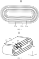
- FIG. 4 is a schematic structural diagram of an electrode assembly according to an embodiment of this application.
- FIG. 5 is a schematic structural diagram of an electrode assembly according to another embodiment of this application.
- the electrode assembly 22 includes multiple electrode plates 25.
- the multiple electrode plates 25 are wound to form the electrode assembly 22. More specifically, the positive electrode plate 221a, the negative electrode plate 221b, and the separator 221c are stacked sequentially and wound to form a jelly-like electrode assembly 22.
- the electrode assembly 22 may alternatively be a laminated electrode assembly 22. This is not particularly limited in this application.
- the battery 10 may be a pouch battery, and the electrode assembly 22 formed by winding the positive electrode plate 221a, negative electrode plate 221b, and separator 221c can be directly placed in the packaging bag.
- the packaging bag may be made of aluminum-plastic film.
- the battery 10 may alternatively be a hard-shell battery as mentioned before.
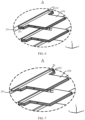
- FIG. 6 is a partially enlarged view of region A of FIG. 5 .
- the electrode assembly 22 includes a body portion 251 and a lead-out portion 252 that are disposed in a first direction X, the body portion 251 being electrically connected to an electrode terminal 241 via the lead-out portion 252.
- the lead-out portion 252 includes a tab portion 253 and a conductive structure 254.
- a first end of the conductive structure 254 is welded to the tab portion 253 to form a welded zone 255, a second end of the conductive structure 254 is connected to the electrode terminal 241, and the conductive structure 254 extends along a direction leaving the body portion 251.
- a melting zone 26 is provided between the welded zone 255 and the body portion 251.
- the electrode assembly 22 includes the body portion 251 and the lead-out portion 252. More specifically, the lead-out portion 252 includes the tab portion 253 and the conductive structure 254. The conductive structure 254 is welded to the tab portion 253 to form the welded zone 255, and the melting zone 26 is provided between the welded zone 255 and the body portion 251.
- the first end of the conductive structure 254 is an end of the conductive structure 254 closer to the tab portion 253, and the second end of the conductive structure 254 is an end of the conductive structure 254 farther away from the tab portion 253.
- the melting zone 26 serves as a fuse in the battery cell 20 and therefore can blow when a large current passes through, preventing risks such as lithium precipitation and excessive heat generation caused by the passage of the large current in the electrode assembly 22, thus reducing the risk of thermal runaway in the battery.
- the conductive structure 254 is directly electrically connected to the electrode terminal 241 without using another component such as an adapter sheet, thereby increasing the weight energy density and production efficiency of the battery 10 and reducing production costs.
- the lead-out portion 252 includes the tab portion 253 and the conductive structure 254, the conductive structure 254 is welded to the tab portion 253 to form the welded zone 255, and the melting zone 26 is provided between the welded zone 255 and the body portion 251.
- the melting zone 26 herein may be a part of the tab portion 253 or exist independently. This is not limited in this application.
- FIG. 7 is another partially enlarged view of region A of FIG. 5 .
- a size of the melting zone 26 is larger than a size of the conductive structure 254, the second direction Y being perpendicular to the first direction X and parallel to the tab portion 253.
- the size of the melting zone 26 in the second direction Y is larger than that of the conductive structure 254, the size of the melting zone 26 in the first direction X or another direction may be smaller than that of the conductive structure 254. Only the size in the second direction Y is limited herein without particularly limiting the sizes in other directions.
- the size of the melting zone 26 in the second direction Y is larger than the size of the conductive structure 254; in other words, the melting zone 26 exceeds the conductive structure 254 in the second direction Y
- a size of the melting zone 26 is not smaller than half the size of the body portion 251.
- the body portion 251 includes a straight portion 2512 and a bent portion 2513.
- the electrode assembly 22 When the electrode assembly 22 is a wound-type electrode assembly 22, it includes the straight portion 2512 and the bent portion 2513.
- the body portion 251 of the electrode assembly 22 includes the straight portion 2512 and the bent portion 2513.
- the size of the melting zone 26 is not larger than a size of the straight portion 2512.
- the size of the melting zone 26 in the second direction Y is made to be not larger than the size of the straight portion 2512; in other words, the melting zone 26 does not need to maintain bent. This can reduce the production difficulty and is advantageous to wide-scale production.
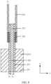
- FIG. 8 is a cross-sectional view of an electrode plate according to an embodiment of this application.
- the electrode assembly 22 includes multiple electrode plates 25, where the electrode plate 25 includes a non-metal layer 256 and a metal layer 257 disposed on two sides of the non-metal layer 256, and the conductive structure 254 is welded to the metal layer 257 of the tab portion 253 to form the welded zone 255.
- the electrode plate 25 includes the non-metal layer 256 and the metal layer 257, where the metal layer 257 is disposed on two sides of the non-metal layer 256. Since the electrode assembly 22 is provided with the non-metal layer 256, the thickness of the metal layer 257 can be reduced. As a result, burrs generated at a part of the metal layer 257 punctured by a foreign matter are small, making it difficult to puncture the separator 221c.
- the size L 1 of the non-metal layer 256 may be 1 ⁇ m to 20 ⁇ m
- the size L 2 of the metal layer 257 may be 0.1 ⁇ m to 10 ⁇ m
- the size L 3 of the conductive structure 254 may be 6 ⁇ m to 15 ⁇ m. Because the metal layer 257 is relatively thin, burrs generated by the metal layer 257 during cutting are small, making it difficult to puncture the separator 221c of a dozen micrometers, thereby avoiding short circuits and improving the safety performance.
- the non-metal layer 256 may be an inorganic material or an organic material, or a conductive non-metal material or a non-conductive non-metal material, that is, an insulating material. This is not limited in this application.
- the electrode plate 25 including the non-metal layer 256 and the metal layer 257 disposed on two sides of the non-metal layer 256, short circuits in the battery 10 can be avoided, thereby improving the safety performance of the battery 10.
- FIG. 9 is still another partially enlarged view of region A of FIG. 5 .
- a size of the melting zone 26 is smaller than a size of the conductive structure 254, the second direction Y being perpendicular to the first direction X and parallel to the tab portion 253.
- the size of the melting zone 26 in the second direction Y is smaller than that of the conductive structure 254
- the size of the melting zone 26 in the first direction X or another direction may be larger than that of the conductive structure 254. Only the size in the second direction Y is limited herein without particularly limiting the size in other directions.
- the size of the melting zone 26 in the second direction Y is smaller than the size of the conductive structure 254; in other words, the melting zone 26 is recessed into the conductive structure 254 in the second direction Y
- a size of the melting zone 26 is smaller than a size of the conductive structure 254, the third direction Z being perpendicular to the first direction X and perpendicular to the tab portion 253.
- the size of the melting zone 26 in the third direction Z is smaller than that of the conductive structure 254, the size of the melting zone 26 in the first direction X or another direction may be larger than that of the conductive structure 254. Only the size in the third direction Z is limited herein without particularly limiting the size in other directions.
- the size of the melting zone 26 in the third direction Z is smaller than the size of the conductive structure 254; in other words, the tab portion 253 is recessed into the conductive structure 254 in the third direction Z.
- the melting zone 26 is provided with a melting hole.
- providing the melting hole on the melting zone 26 can further reduce the current flow capability of the melting zone 26, thereby further reducing the risk of thermal runaway in the battery 10.
- the battery cell 20 further includes a separator 221c, where the separator 221c covers the melting hole.
- the multiple electrode plates 25 form the electrode assembly 22.
- the melting hole is provided on the melting zone 26, it is likely that burrs of the melting hole puncture the electrode plate 25, in spite of a wound electrode assembly 22 or a laminated electrode assembly 22.
- covering the melting hole with the separator 221c can prevent burrs generated during preparation of the melting hole from puncturing the electrode plate 25, while such puncturing affects performance of the battery 10.
- FIG. 10 is a cross-sectional view of an electrode plate according to another embodiment of this application.
- the tab portion 253 includes a first tab portion 2531 and a second tab portion 2532, where the first tab portion 2531 is disposed between the body portion 251 and the second tab portion 2532, and in the second direction Y, a size of the first tab portion 2531 is larger than a size of the second tab portion 2532.
- the size of the first tab portion 2531 is larger than the size of the second tab portion 2532.
- the first tab portion 2531 connected to the body portion 251 has a larger size in the second direction Y, which can increase the connection area between the body portion 251 and the tab portion 253, thereby increasing the connection strength between the two.
- the second tab portion 2532 having a smaller size can reduce the space occupied by the entire tab portion 253 in the battery cell 20.
- the tab portion 253 includes the first tab portion 2531 and the second tab portion 2532, and the size of the first tab portion 2531 connected to the body portion 251 is made larger than the size of the second tab portion 2532. This not only can increase the connection strength between the tab portion 253 and the body portion 251, but also can reduce the space occupied by the entire tab portion 253 in the battery cell 20.
- the welded zone 255 includes a first welded zone 2551 and a second welded zone 2552, where the first welded zone 2551 is located on the first tab portion 2531, the second welded zone 2552 is located on the second tab portion 2532, and in the second direction Y, a size of the first welded zone 2551 is larger than a size of the second welded zone 2552.
- the first welded zone 2551 is located on the first tab portion 2531 that has a larger size in the second direction Y
- the second welded zone 2552 is located on the second tab portion 2532 that has a smaller size in the second direction Y
- the first welded zone 2551 is located on the first tab portion 2531 that has a larger size in the second direction Y, allowing for a larger welding area between the conductive structure 254 and the first tab portion 2531, thereby increasing the connection strength between the two.
- an active substance layer 2511 is disposed on an outer surface of the body portion 251.
- the multiple electrode plates 25 are wound to form the electrode assembly 22.
- the electrode assembly 22 includes the body portion 251 and the lead-out portion 252. Further, the lead-out portion 252 includes the tab portion 253 and the conductive structure 254. The tab portion 253 is welded to the conductive structure 254 to create an electrical connection. More specifically, the electrode plate 25 includes the metal layer 257 and the non-metal layer 256, where the metal layer 257 is disposed on two sides of the non-metal layer 256. In other words, the conductive structure 254 is welded to the metal layer 257 of the tab portion 253 to form the welded zone 255, and the metal layer 257 of the body portion 251 is coated with the active substance layer 2511.
- the current generated by the active substance in the active substance layer 2511 is collected to form a larger current for external output.
- the active substance layer 2511 disposed on the outer surface of the body portion 251, namely, the metal layer 257 of the body portion 251, the active substance layer 2511 can undergo electrochemical reactions during charging and discharging of the battery 10, achieving the conversion between chemical energy and electrical energy.
- a first protective layer 2514 is provided at an end of the tab portion 253 close to the body portion 251, where the first protective layer 2514 is disposed between the body portion 251 and the melting zone 26.
- the first protective layer 2514 is disposed on a part of the tab portion 253 that is neither covered by the active substance nor connected to the conductive structure 254.
- the first protective layer 2514 may be directly disposed on the surface of the tab portion 253 farther away from the non-metal layer 256; in other words, the first protective layer 2514 is disposed on the metal layer 257 of the tab portion 253.
- a coating may be applied on the surface of the tab portion 253 farther away from the non-metal layer 256, and the first protective layer 2514 is disposed on the surface of the coating.
- the first protective layer 2514 is connected to the active substance layer 2511 so that the first protective layer 2514 is fixed to the active substance layer 2511, increasing the bonding strength of the first protective layer 2514 to the electrode plate 25, thereby preventing the first protective layer 2514 from falling off.
- an end of the first protective layer 2514 may be connected to the active substance layer 2511, allowing the first protective layer 2514 to cover the junction between the body portion 251 and the tab portion 253. This prevents the metal layer 257 from fracturing, thus affecting the current flow capability of the electrode plate 25.
- the coating zone covers an end of the active substance layer 2511.
- the stiffness of the first protective layer 2514 can be made higher than the stiffness of the metal layer 257. This can further prevent the tab portion 253 from deforming and prevent the metal layer 257 from rupturing.
- first protective layer 2514 being disposed between the conductive structure 254 and the active substance layer 2511 means the active substance layer 2511, the first protective layer 2514, the melting zone 26, and the conductive structure 254 being disposed sequentially in the first direction X.
- disposing the first protective layer 2514 on the tab portion 253 that is neither covered by the active substance nor connected to the conductive structure 254 can provide support to the tab portion 253, limiting deformation of the tab portion 253. As a result, this prevents fracture of the metal layer 257, thereby improving the current flow capability of the electrode plate 25.
- FIG. 11 is a cross-sectional view of an electrode plate according to still another embodiment of this application. As shown in FIG. 11 , in the first direction X, a size L 4 of the first protective layer 2514 is 0.1 mm to 6 mm.
- the tab portion 253 is usually bent to form the first tab 222a (or the second tab 222b) to reduce the space occupied by the tab portion 253 in the third direction Z and increase the energy density of the battery 10. Due to the high stiffness of the first protective layer 2514, the region of the tab portion 253 covered by the first protective layer 2514 cannot be bent.
- the first protective layer 2514 occupying excessive space also reduces the region for welding the tab portion 253 to the conductive structure 254, reducing the current flow capability between the conductive structure 254 and the tab portion 253.
- keeping the size L 4 of the first protective layer 2514 in the first direction X within 0.1 mm to 6 mm can not only provide support to the tab portion 253 but also ensure good current flow capability between the conductive structure 254 and the tab portion 253 as well as ensure the energy density of the battery 10.
- a size of the first protective layer 2514 is 0.5 mm to 4 mm.
- keeping the size of the first protective layer 2514 in the first direction X within 0.5 mm to 4 mm can provide support to the tab portion 253 and reserve enough region for the melting zone 26.
- the size L 5 of the melting zone 26 is 0.01 mm to 2 mm.
- the melting zone 26 is provided between the first protective layer 2514 and the conductive structure 254. If the size of the melting zone 26 is too small, a part of the conductive structure 254 connected to the tab portion 253 may overlap with the first protective layer 2514 because of error, causing the conductive structure 254 to tilt and resulting in poor welding to the tab portion 253, thereby affecting the service life of the battery 10. In addition, because the first protective layer 2514 has a high stiffness, the first protective layer 2514 may probably damage the welding device.
- the conductive structure 254 may still overlap with the first protective layer 2514 because of error. If the size L 5 of the melting zone 26 in the first direction X is larger than 2 mm, when the tab portion 253 is bent, the part of the tab portion 253 corresponding to the melting zone 26 creases, leading to fracture of the metal layer 257.
- a size L 5 of the melting zone 26 is 0.05 mm to 1.5 mm.
- a second protective layer 2533 is disposed on a surface of the welded zone 255 farther away from the tab portion 253.
- the separator 221c may be punctured, posing a short circuit risk.
- disposing the second protective layer 2533 on the surface of the welded zone 255 farther away from the tab portion 253 can separate the surface of the welded zone 255 from the separator 221c, preventing the separator 221c from being punctured, thus further improving the safety performance of the battery 10.
- both the first protective layer 2514 and the second protective layer 2533 are made of an insulating material.
- the insulating material may be at least one of alumina trihydrate or hydroxide alumina.
- the first protective layer 2514 and the second protective layer 2533 may further include a binder.
- the binder is mixed with the insulating material to prepare a slurry.
- the slurry is applied on the surface of the tab portion 253 or the surface of the welded zone 255 farther away from the tab portion 253, and then cured to form the first protective layer 2514 and the second protective layer 2533.
- both the first protective layer 2514 and the second protective layer 2533 being made of an insulating material can prevent the first protective layer 2514 and second protective layer 2533 from affecting a current flow path of the electrode plate 25 in the electrode assembly 22, thus ensuring the safety of the electrical connection of the electrode plate 25.
- the size L 6 of the melting zone 26 in the second direction Y is A H 1 ⁇ C where A represents the current flow area of the battery cell 20, H 1 represents the total thickness of the conductive structure 254 in the third direction Z, and C represents the number of the conductive structures 254.
- H 1 may be the total thickness of the conductive structure 254 in the third direction Z.
- the electrode assembly 22 may have multiple conductive structures 254, and after electrode plates 25 are wound, the multiple conductive structures 254 are opposite in position.
- the multiple conductive structures 254 are stacked together and connected to one electrode terminal 241. Therefore, the number C of conductive structures 254 connected to one electrode terminal 241 is introduced in the formula. For example, in FIG. 5 , there are four conductive structures 254, and C takes the value of four in the formula for calculation; and in FIG. 6 , there are two conductive structures 254, and C takes the value of two in the formula for calculation.
- A represents the current flow area of the battery cell 20.
- the value of A is not limited in any way in this application, meaning that A can be any constant value.
- the value of A is related to the specific performance of the battery 10 and is not discussed in detail herein.
- the size L 6 of an end of the welded zone 255 close to the body portion 251 in the second direction Y needs to be 100 mm to ensure that the melting zone 26 can serve as a fuse, so as to ensure the safety of the battery 10.
- An embodiment of this application further provides a battery 10, where the battery 10 may include the battery cell 20 in the foregoing embodiments.
- the battery 10 may also include other structures such as a box 11 and a busbar. Details are not described herein.
- An embodiment of this application further provides an electric device, where the electric device may include the battery 10 in the foregoing embodiments.
- the electric device can be a vehicle 1, ship, spacecraft, or the like, which is not limited in the embodiment of this application.
Landscapes
- Chemical & Material Sciences (AREA)
- Chemical Kinetics & Catalysis (AREA)
- Electrochemistry (AREA)
- General Chemical & Material Sciences (AREA)
- Connection Of Batteries Or Terminals (AREA)
Abstract
Description
- This application relates to the field of battery technologies, and in particular, to a battery cell, a battery, and an electric device.
- Energy conservation and emission reduction are crucial to sustainable development of the automobile industry. In this context, electric vehicles, with their advantages in energy conservation and emission reduction, have become an important part of sustainable development of the automobile industry. For electric vehicles, battery technology is an important factor in connection with their development.
- In the development of battery technology, in addition to improving the performance of the battery, the occurrence of thermal runaway inside batteries is also a non-negligible issue. If thermal runaway occurs inside a battery, the battery becomes unusable. Therefore, how the probability of thermal runaway inside batteries is reduced is an urgent problem to be resolved in battery technology.
- In view of the foregoing issue, embodiments of this application provide a battery cell, a battery, and an electric device, to reduce the probability of thermal runaway in batteries.
- According to a first aspect, a battery cell is provided, including an electrode assembly including a body portion and a lead-out portion that are disposed in a first direction, the body portion being electrically connected to an electrode terminal via the lead-out portion. The lead-out portion includes a tab portion and a conductive structure. A first end of the conductive structure is welded to the tab portion to form a welded zone, a second end of the conductive structure is connected to the electrode terminal, and the conductive structure extends in a direction leaving the body portion. A melting zone is provided between the welded zone and the body portion.
- In this embodiment of this application, the electrode assembly includes the body portion and the lead-out portion. Further, the lead-out portion includes the tab portion and the conductive structure. The conductive structure is welded to the tab portion to form the welded zone, and the melting zone is provided between the welded zone and the body portion. With the melting zone provided between the body portion and the welded zone and the welded zone formed by welding the tab portion to the conductive structure, the melting zone serves as a fuse in the battery cell and therefore can blow when a large current passes through, preventing risks such as lithium precipitation and excessive heat generation caused by the passage of the large current in the electrode assembly, thus reducing the risk of thermal runaway in the battery. In addition, the conductive structure is directly electrically connected to the electrode terminal without using another component such as an adapter sheet, thereby increasing the weight energy density and production efficiency of the battery and reducing production costs.
- In a possible embodiment, in a second direction, a size of the melting zone is larger than a size of the conductive structure, the second direction being perpendicular to the first direction and parallel to the tab portion.
- In this embodiment of this application, with the welded zone formed by the tab portion and the conductive structure and the melting zone located between the body portion and the welded zone, the size of the melting zone in the second direction is larger than the size of the conductive structure; in other words, the melting zone exceeds the conductive structure in the second direction.
- In a possible embodiment, in the second direction, a size of the melting zone is not smaller than half the size of the body portion.
- In this embodiment of this application, making the size of the melting zone in the second direction not smaller than half the size of the body portion can increase the current flow area of the melting zone and reduce heat generation.
- In a possible embodiment, the body portion includes a straight portion and a bent portion.
- In this embodiment of this application, when the electrode assembly is of a wound type, that is, when multiple electrode plates are wound to form the electrode assembly, the body portion of the electrode assembly includes the straight portion and the bent portion.
- In a possible embodiment, in the second direction, the size of the melting zone is not larger than a size of the straight portion.
- In this embodiment of this application, the size of the melting zone in the second direction is made to be not larger than the size of the straight portion, that is, the melting zone does not need to maintain bent. This can reduce the production difficulty and is advantageous to wide-scale production.
- In a possible embodiment, the electrode assembly includes multiple electrode plates, where the electrode plate includes a non-metal layer and a metal layer disposed on two sides of the non-metal layer, and the conductive structure is welded to the metal layer of the tab portion to form the welded zone.
- In this embodiment of this application, the electrode assembly includes multiple electrode plates. Further, the electrode plate includes the non-metal layer and the metal layer, where the metal layer is disposed on two sides of the non-metal layer. Since the electrode plate is provided with the non-metal layer, the thickness of the metal layer can be reduced. As a result, burrs generated at a part of the metal layer punctured by a foreign matter are small, making it difficult to puncture the separator. The electrode plate including the non-metal layer and metal layer disposed on two sides of the non-metal layer can reduce the risk of short circuits of the battery caused by a foreign matter puncturing the metal layer.
- In a possible embodiment, the electrode assembly includes multiple electrode plates, where the electrode plate includes a non-metal layer and a metal layer disposed on two sides of the non-metal layer, and the conductive structure is welded to the metal layer of the tab portion to form the welded zone.
- In this embodiment of this application, the electrode assembly includes multiple electrode plates. Further, the electrode plate includes the non-metal layer and the metal layer, where the metal layer is disposed on two sides of the non-metal layer. Since the electrode plate is provided with the non-metal layer, the thickness of the metal layer can be reduced. As a result, burrs generated at a part of the metal layer punctured by a foreign matter are small, making it difficult to puncture the separator. The electrode plate including the non-metal layer and metal layer disposed on two sides of the non-metal layer can reduce the risk of short circuits of the battery caused by a foreign matter puncturing the metal layer.
- In a possible embodiment, in a second direction, a size of the melting zone is smaller than a size of the conductive structure, the second direction being perpendicular to the first direction and parallel to the tab portion.
- In this embodiment of this application, with the welded zone formed by the tab portion and the conductive structure and the melting zone located between the body portion and the welded zone, the size of the melting zone in the second direction is smaller than the size of the conductive structure; in other words, the melting zone is recessed into the conductive structure in the second direction.
- In a possible embodiment, in a third direction, a size of the melting zone is smaller than a size of the conductive structure, the third direction being perpendicular to the first direction and perpendicular to the tab portion.
- In this embodiment of this application, with the welded zone formed by the tab portion and the conductive structure and the welded zone located between the body portion and the welded zone, the size of the melting zone in the third direction is smaller than the size of the conductive structure; in other words, the tab portion is recessed into the conductive structure in the third direction.
- In a possible embodiment, the melting zone is provided with a melting hole.
- In this embodiment of this application, providing the melting hole on the melting zone can further reduce the current flow capability of the melting zone, thereby further reducing the risk of thermal runaway in the battery.
- In a possible embodiment, the battery cell further includes a separator, where the separator covers the melting hole.
- In this embodiment of this application, covering the melting hole with the separator can prevent burrs generated during preparation of the melting hole from puncturing the electrode plate, while such puncturing affects performance of the battery.
- In a possible embodiment, the tab portion includes a first tab portion and a second tab portion, where the first tab portion is disposed between the body portion and the second tab portion, and in the second direction, a size of the first tab portion is larger than a size of the second tab portion.
- In this embodiment of this application, in the second direction, the size of the first tab portion is larger than the size of the second tab portion. In other words, the first tab portion connected to the body portion has a larger size in the second direction, which can increase the connection area between the body portion and the tab portion, thereby increasing the connection strength between the two. Additionally, the second tab portion having a smaller size can reduce the space occupied by the entire tab portion in the battery while a stable connection between the tab portion and the body portion is ensured.
- In a possible embodiment, the welded zone includes a first welded zone and a second welded zone, where the first welded zone is located on the first tab portion, the second welded zone is located on the second tab portion, and in the second direction, a size of the first welded zone is larger than a size of the second welded zone.
- In this embodiment of this application, the first welded zone is located on the first tab portion that has a larger size in the second direction, allowing for a larger welding area between the conductive structure and the first tab portion, thereby increasing the connection strength between the two.
- In a possible embodiment, a first protective layer is provided at an end of the tab portion close to the body portion, where the first protective layer is disposed between the body portion and the melting zone.
- In a possible embodiment, a first protective layer is provided at an outer surface of a part of the tab portion, where the part of the tab portion is not covered by the conductive structure and does not serve as the melting zone, and the first protective layer is disposed between the body portion and the melting zone.
- In this embodiment of this application, the first protective layer is disposed on a part of the tab portion that is neither covered by the active substance nor connected to the conductive structure and that does not serve as the melting zone. Further, the stiffness of the first protective layer can be larger than the stiffness of the metal layer. This allows the first protective layer to have a larger stiffness so as to support the tab portion and limit deformation of the tab portion, thereby preventing the metal layer from rupturing, and improving the current flow capability of the electrode plate.
- In a possible embodiment, in the first direction, a size of the first protective layer is 0.1 mm to 6 mm.
- In this embodiment of this application, the size of the first protective layer in the first direction directly affects the effects of the first protective layer in protecting the tab portion. If the size of the first protective layer is too small, the adhesion between the first protective layer and the tab portion is weak, making them prone to fall off, and the coverage area is small, leading to weak capability to inhibit deformation of the tab portion is weak. If the size of the first protective layer is too large, the connection area between the tab portion and the conductive structure is reduced, decreasing the current flow capability between the conductive structure and the electrode assembly. The first protective layer with the size in the first direction maintained within 0.1 mm to 6 mm can not only support the tab portion but also ensure good current flow capability between the conductive structure and the electrode assembly.
- In a possible embodiment, in the first direction, a size of the first protective layer is 0.5 mm to 4 mm.
- In this embodiment of this application, keeping the size of the first protective layer in the first direction within 0.5 mm to 4 mm can provide support to the tab portion and reserve enough region for the melting zone.
- In a possible embodiment, in the first direction, a size of the melting zone is 0.01 mm to 2 mm.
- In this embodiment of this application, the first protective layer is disposed on a part of the tab portion that is neither covered by the active substance nor connected to the conductive structure and that does not serve as the melting zone. If the size of the melting zone is too small, a part of the conductive structure may overlap with the first protective layer, resulting in tilt of the conductive structure and thus poor connection, thereby affecting the service life of the battery. Making the size of the melting zone in the first direction fall within 0.01 mm to 2 mm can ensure the normal service life of the battery.
- In a possible embodiment, in the first direction, a size of the first protective layer is 0.05 mm to 1.5 mm.
- In this embodiment of this application, making the size of the melting zone in the first direction fall within 0.05 mm to 1.5 mm can further ensure the normal service life of the battery.
- In a possible embodiment, a second protective layer is disposed on a surface of the welded zone away from the tab portion.
- In this embodiment of this application, since the conductive structure and the tab portion are connected through welding, the surface of the welded zone may become uneven. As a result, the separator may be punctured, posing a short circuit risk. With the second protective layer provided on the surface of the welded zone, the surface of the welded zone can be separated from the separator, preventing the separator from being punctured, thus further improving the safety performance of the battery.
- In a possible embodiment, both the first protective layer and the second protective layer are made of an insulating material.
- In this embodiment of this application, the insulating material does not have the function of electrical connection. Both the first protective layer and the second protective layer being made of an insulating material can prevent the first protective layer and second protective layer from affecting a current flow path of the electrode plate in the electrode assembly, thus ensuring the safety of the electrical connection of the electrode plate.
- According to a second aspect, a battery is provided, including the battery cell according to any one of the embodiments of the first aspect.
- According to a third aspect, an electric device is provided, including the battery according to the second aspect, where the battery is configured to supply electric energy.
- In the technical solutions of this application, the electrode assembly includes the body portion and the lead-out portion, and the lead-out portion includes the tab portion and the conductive structure. In the technical solutions of this application, the first end of the conductive structure is welded to the tab portion to form the welded zone, the melting zone is provided between the welded zone and the body portion, and another end of the conductive structure is directly connected to the electrode terminal. The melting zone can serve as a fuse and therefore can melt the tab portion when a large current passes through, preventing risks of lithium precipitation and excessive heat generation caused by the passage of the large current in the electrode assembly, thus reducing the risk of thermal runaway in the battery. In addition, the conductive structure is directly connected to the end cover without using another component such as an adapter sheet, thereby increasing the weight energy density and production efficiency of the battery and reducing production costs.
- To describe the technical solutions of the embodiments of this application more clearly, the following briefly describes the accompanying drawings required for describing the embodiments of this application. Apparently, the accompanying drawings described below show merely some embodiments of this application, and persons of ordinary skill in the art may still derive other drawings from the accompanying drawings without creative efforts.
-
FIG. 1 is a schematic structural diagram of a vehicle according to an embodiment of this application; -
FIG. 2 is a schematic structural exploded view of a battery according to an embodiment of this application; -
FIG. 3 is a schematic structural exploded view of a battery cell according to an embodiment of this application; -
FIG. 4 is a schematic structural diagram of an electrode assembly according to an embodiment of this application; -
FIG. 5 is a schematic structural diagram of an electrode assembly according to another embodiment of this application; -
FIG. 6 is a partially enlarged view of region A ofFIG. 5 ; -
FIG. 7 is another partially enlarged view of region A ofFIG. 5 ; -
FIG. 8 is a cross-sectional view of an electrode plate according to an embodiment of this application; -
FIG. 9 is still another partially enlarged view of region A ofFIG. 5 ; -
FIG. 10 is a cross-sectional view of an electrode plate according to another embodiment of this application; and -
FIG. 11 is a cross-sectional view of an electrode plate according to still another embodiment of this application. - In the accompanying drawings, the figures are not necessarily drawn to scale.
- Reference signs in the description of embodiments are described as follows:
-
vehicle 1; -
battery 10,controller 30, andmotor 40; -
box 11,battery cell 20,housing 21,electrode assembly 22, accommodatingspace 23,end cover 24,electrode plate 25, andmelting zone 26; -
upper box body 111,lower box body 112,positive electrode plate 221a,negative electrode plate 221b,separator 221c,first tab 222a,second tab 222b,electrode terminal 241,positive electrode terminal 241a,negative electrode terminal 241b,body portion 251, lead-outportion 252,tab portion 253,conductive structure 254, weldedzone 255,non-metal layer 256,metal layer 257; and -
active substance layer 2511,straight portion 2512,bent portion 2513, firstprotective layer 2514,first tab portion 2531,second tab portion 2532, secondprotective layer 2533, first weldedzone 2551, second weldedzone 2552, first direction X, second direction Y, and third direction Z. - The following further describes embodiments of this application in detail with reference to the accompanying drawings and examples. The detailed description of the embodiments and the accompanying drawings are intended to illustrate the principle of this application, rather than to limit the scope of this application, meaning this application is not limited to the embodiments described herein.
- In the descriptions of this application, it should be noted that, unless otherwise stated, "plurality" means two or more; and the orientations or positional relationships indicated by the terms "upper", "lower", "left", "right", "inside", "outside", and the like are merely intended to help the descriptions of this application and simplify the descriptions rather than to indicate or imply that the apparatuses or components must have specific orientations, or be constructed and manipulated with specific orientations, and therefore shall not be construed as limitations on this application. In addition, the terms "first", "second", and "third" are merely intended for a purpose of description, and shall not be understood as an indication or implication of relative importance. "Vertical" means being vertical with an allowable range of error other than being strictly vertical. "Parallel" means being parallel with an allowable range of error other than being strictly parallel.
- The orientation terms appearing in the following description all are directions shown in the figures, and do not limit the specific structure of this application. In the descriptions of this application, it should be further noted that unless otherwise specified and defined explicitly, the terms "installment", "link", and "connection" should be understood in their general senses. For example, the terms may be a fixed connection, a detachable connection, or an integrated connection, or may be a direct connection, or an indirect connection through an intermediate medium. A person of ordinary skill in the art can understand specific meanings of these terms in this application based on specific situations.
- The term "and/or" in this application is only an associative relationship for describing associated objects, indicating that three relationships may be present. For example, A and/or B may indicate three cases: presence of only A; presence of both A and B; and presence of only B. In addition, the character "/" in this application generally indicates an "or" relationship between contextually associated objects.
- Unless otherwise defined, all technical and scientific terms used in this application shall have the same meanings as commonly understood by those skilled in the art to which this application relates. The terms used in the specification of this application are intended to merely describe the specific embodiments rather than to limit this application. The terms "include", "include", and any variations thereof in the specification and claims of this application as well as the foregoing description of drawings are intended to cover non-exclusive inclusions. In the specification, claims, or accompanying drawings of this application, the terms "first", "second", and the like are intended to distinguish between different objects rather than to indicate a particular order or relative importance.
- Reference to "embodiment" in this application means that specific features, structures, or characteristics described with reference to the embodiment may be included in at least one embodiment of this application. The word "embodiment" appearing in various places in the specification does not necessarily refer to the same embodiment or an independent or alternative embodiment that is exclusive of other embodiments. A person skilled in the art can clearly and implicitly understand that the embodiments described in this application can be combined with other embodiments.
- In the embodiments of this application, the battery cell may include a lithium-ion secondary battery, a lithium-ion primary battery, a lithium-sulfur battery, a sodium-lithium-ion battery, a sodium-ion battery, a magnesium-ion battery, or the like. This is not limited in the embodiments of this application. The battery cell may be cylindrical, flat, cuboid, or of other shapes. This is not limited in the embodiments of this application either. Battery cells are typically divided into three types by packaging method: cylindrical cell, prismatic cell, and pouch cell. This is not limited in the embodiments of this application either.
- The battery mentioned in the embodiments of this application is a single physical module that includes one or more battery cells for providing a higher voltage and capacity. For example, the battery mentioned in this application may include a battery module, a battery pack, or the like. A battery typically includes a box configured to enclose one or more battery cells. The box can prevent liquids or other foreign matter from affecting charging or discharging of the battery cell.
- The battery cell may include an electrode assembly and an electrolyte. The electrode assembly includes a positive electrode plate, a negative electrode plate, and a separator. Working of the battery cell mainly relies on migration of metal ions between the positive electrode plate and the negative electrode plate. The positive electrode plate includes a positive electrode current collector and a positive electrode active substance layer. The positive electrode active substance layer is applied on a surface of the positive electrode current collector. The part of positive electrode current collector uncoated with the positive electrode active substance layer protrudes out of the part of positive electrode current collector coated with the positive electrode active substance layer and serves as a positive tab. A lithium-ion battery is used as an example, for which, the positive electrode current collector may be made of aluminum and the positive electrode active substance may be lithium cobaltate, lithium iron phosphate, ternary lithium, lithium manganate, or the like. The negative electrode plate includes a negative electrode current collector and a negative electrode active substance layer. The negative electrode active substance layer is applied on a surface of the negative electrode current collector. The part of negative electrode current collector uncoated with the negative electrode active substance layer protrudes out of the part of negative electrode current collector coated with the negative electrode active substance layer and serves as a negative tab. The negative electrode current collector may be made of copper, and the negative electrode active substance may be graphite, carbon, silicon, or the like. To allow a large current to pass through without any fusing, multiple positive tabs are provided and stacked together, and multiple negative tabs are provided and stacked together. The separator may be made of polypropylene (polypropylene, PP), polyethylene (polyethylene, PE), or the like. In addition, the electrode assembly may be a wound structure or a laminated structure, but the embodiments of this application are not limited thereto.
- Currently, from a perspective of market development, application of electric vehicle batteries is becoming more and more extensive. Electric vehicle batteries have been widely used in energy storage power supply systems such as hydroelectric power plants, thermal power plants, wind power plants, and solar power plants, and many other fields including electric transportation tools such as electric bicycles, electric motorcycles, and electric vehicles, military equipment, and aerospace. With continuous expansion of application fields of electric vehicle batteries, market demands for electric vehicle batteries are also expanding.
- For the development of battery technologies, many design factors need to be considered, for example, performance parameters such as energy density, cycling performance, discharge capacity, and charge and discharge rate, as well as safety performance and production costs of batteries.
- Currently, in some batteries made from special current collectors such as composite substrate current collectors, because the conductive metal layer is relatively thin, if the tab portion responsible for current flow in the composite substrate current collector is designed in the same way as that of a conventional battery having a copper or aluminum foil current collector, the secondary current flow capability is lower than the current flow capability the adapter sheet. Therefore, the size of the tab portion of the battery needs to be designed based on the current flow capability of the adapter sheet for a proper match. When a large tab portion is designed to match the current flow capability of the adapter sheet, the large tab portion interferes with the structure of the end cover of the battery to some degree, affecting the performance of the battery. Therefore, how the safety performance of batteries prepared using such composite substrate current collector is an issue to be solved urgently at present.
- In view of this, an embodiment of this application provides an electrode assembly. The electrode assembly includes a body portion and a lead-out portion. The lead-out portion includes a tab portion and a conductive structure. A first end of the conductive structure is welded to the tab portion to form a welded zone, a melting zone is provided between the welded zone and the body portion, and another end of the conductive structure is directly connected to an electrode terminal. The melting zone can serve as a fuse and therefore can melt the tab portion when a large current passes through, preventing risks of lithium precipitation and excessive heat generation caused by the passage of the large current in the electrode assembly, thus reducing the risk of thermal runaway in the battery. In addition, the conductive structure is directly connected to the end cover without using another component such as an adapter sheet, thereby increasing the weight energy density and production efficiency of the battery and reducing production costs.
- The technical solutions described in the embodiments of this application are all applicable to various devices using batteries, such as mobile phones, portable devices, notebook computers, electric bicycles, electric toys, electric tools, electric vehicles, ships, and spacecraft. For example, the spacecraft includes planes, rockets, space shuttles, spaceships, and the like.
- It should be understood that the technical solutions described in the embodiments of this application are not only applicable to the devices described above, but also applicable to all devices using batteries. However, for brevity of description, in the following embodiments, the electric vehicle is used as an example for description.
- For example,
FIG. 1 is a schematic structural diagram of a vehicle according to an embodiment of this application. As shown inFIG. 1 , thevehicle 1 may be a fossil fuel vehicle, a natural-gas vehicle, or a new energy vehicle, where the new energy vehicle may be a battery electric vehicle, a hybrid electric vehicle, a range-extended vehicle, or the like. Amotor 40, acontroller 30, and abattery 10 may be provided inside thevehicle 1, where thecontroller 30 is configured to control thebattery 10 to supply power to themotor 40. For example, thebattery 10 may be disposed at the bottom, front, or rear of thevehicle 1. Thebattery 10 may be configured to supply power to thevehicle 1. For example, thebattery 10 may be used as an operational power source for thevehicle 1 which is configured for a circuit system of thevehicle 1, for example, to satisfy power needs of start, navigation, and running of thevehicle 1. In another embodiment of this application, thebattery 10 can be used not only as the operational power source for thevehicle 1, but also as a driving power source for thevehicle 1, replacing or partially replacing fossil fuel or natural gas to provide driving traction for thevehicle 1. - To meet different requirements for power use, the
battery 10 may include a plurality of battery cells.FIG. 2 is a schematic structural exploded view of abattery 10 according to an embodiment of this application. As shown inFIG. 2 , thebattery 10 may include a plurality ofbattery cells 20. According to different requirements for electricity, the number of thebattery cells 20 may be set to any numerical value. Themultiple battery cells 20 may be connected in series, in parallel, or in series and parallel to achieve greater capacity or power. Because the number ofbattery cells 20 included in eachbattery 10 may be large, for ease of installation, thebattery cells 20 may be arranged in groups, and each group ofbattery cells 20 forms a battery module. The number ofbattery cells 20 included in the battery module is not limited, and may be set according to requirements. A battery may include multiple battery modules. These battery modules may be connected in series, parallel, or series-parallel. - Optionally, the
battery 10 may further include other structures. For example, thebattery 10 may also include a busbar that is used to implement electrical connection between themultiple battery cells 20, for example, in parallel, in series, or in hybrid connection. Specifically, the busbar may enable the electrical connection between thebattery cells 20 by connecting the electrode terminals of thebattery cells 20. Further, the busbar may be fixed to the electrode terminals ofbattery cells 20 by welding. Electrical energy of the plurality ofbattery cells 20 can be further drawn out of the box through a conductive mechanism. Optionally, the conductive structure may also belong to the busbar. - The
battery 10 may further include a box 11 (or referred to as a cover), where thebox 11 has a hollow structure inside, and the plurality ofbattery cells 20 are accommodated in thebox 11. As shown inFIG. 2 , thebox 11 may include two portions: anupper box body 111 and alower box body 112. Theupper box body 111 and thelower box body 112 are snap-fitted together. Shapes of theupper box body 111 and thelower box body 112 may be determined based on a shape of the plurality of combinedbattery cells 20, and at least one of theupper box body 111 and thelower box body 112 has an opening. For example, one of theupper box body 111 and thelower box body 112 included in thebox 11 is a hollow cuboid with an opening, and the other is plate shaped for covering the opening. For example, as shown inFIG. 2 , thelower box body 112 is a hollow cuboid and has only one face with an opening and theupper box body 111 is plate shaped. In such case, theupper box body 111 covers the opening of thelower box body 112 to form thebox 11 with a closed chamber. The chamber may be configured to accommodate themultiple battery cells 20. - Optionally, the
upper box body 111 and thelower box body 112 included in thebox 11 in this embodiment of this application may be in other shapes. For example, theupper box body 111 and thelower box body 112 each may be a hollow cuboid and have only one face with an opening, where the opening of theupper box body 111 is disposed opposite the opening of thelower box body 112, and theupper box body 111 and thelower box body 112 are snap-fitted to form thebox 11 with a closed chamber. Themultiple battery cells 20 are connected in parallel, in series, or in series-parallel, and then placed into the box formed after theupper box body 111 and thelower box body 112 are snap-fitted. -
FIG. 3 is a schematic structural exploded view of abattery cell 20 according to an embodiment of this application. As shown inFIG. 3 , thebattery cell 20 includes one ormore electrode assemblies 22, ahousing 21, and anend cover 24. Thehousing 21 and theend cover 24 form an outer shell or battery case. The wall of thehousing 21 as well as theend cover 24 are referred to as the walls of thebattery cell 20. For a rectangular-type battery cell 20, the walls of thehousing 21 include a bottom wall and four side walls, where the bottom wall and the four side walls are connected to form anaccommodating space 23 for placing theelectrode assembly 22. Thehousing 21 depends on a combined shape of the one ormore electrode assemblies 22. For example, thehousing 21 may be a hollow cuboid, a cube, or a cylinder, and one surface of thehousing 21 has an opening for placing the one ormore electrode assemblies 22 into thehousing 21. For example, when thehousing 21 is a hollow cuboid or cube, one face of thehousing 21 is an opening face, which means that the face has no wall so that the inside and the outside of thehousing 21 are communicated. When thehousing 21 is a hollow cylinder, the end face of thehousing 21 is an opening face, which means that the end face has no wall so that the inside and the outside of thehousing 21 are communicated. The end cover 24 covers the opening of theaccommodating space 23 and is coupled to thehousing 21 to form a closed cavity in which theelectrode assembly 22 is placed. Thehousing 21 is filled with an electrolyte, for example, a liquid electrolyte. - The
battery cell 20 may also include twoelectrode terminals 241 and the twoelectrode terminals 241 may be disposed on theend cover 24. Theend cover 24 is generally in a shape of a flat plate, and twoelectrode terminals 241 are fixed on a flat surface of theend cover 24. The twoelectrode terminals 241 are apositive electrode terminal 241a and anegative electrode terminal 241b respectively. Eachelectrode terminal 241 is provided with one correspondingconductive structure 254 that is located between theend cover 24 and theelectrode assembly 22 and that is configured to electrically connect theelectrode assembly 22 to theelectrode terminal 241. - As shown in
FIG. 3 , eachelectrode assembly 22 has afirst tab 222a and asecond tab 222b. Thefirst tab 222a and thesecond tab 222b have opposite polarities. For example, when thefirst tab 222a is a positive tab, thesecond tab 222b is a negative tab. In this embodiment of this application, thefirst tabs 222a of the one ormore electrode assemblies 22 are connected to oneelectrode terminal 241 through oneconductive structure 254, and thesecond tabs 222b of the one ormore electrode assemblies 22 are connected to theother electrode terminal 241 through the otherconductive structure 254. For example, thepositive electrode terminal 241a is connected to the positive electrode tab through oneconductive structure 254, and thenegative electrode terminal 241b is connected to the negative electrode tab through the otherconductive structure 254. - In the
battery cell 20, one ormore electrode assemblies 22 may be provided depending on an actual need. As shown inFIG. 3 , thebattery cell 20 is provided with fourindependent electrode assemblies 22. -
FIG. 4 is a schematic structural diagram of an electrode assembly according to an embodiment of this application.FIG. 5 is a schematic structural diagram of an electrode assembly according to another embodiment of this application. As shown inFIG. 4 and FIG. 5 , theelectrode assembly 22 includesmultiple electrode plates 25. Themultiple electrode plates 25 are wound to form theelectrode assembly 22. More specifically, thepositive electrode plate 221a, thenegative electrode plate 221b, and theseparator 221c are stacked sequentially and wound to form a jelly-like electrode assembly 22. Theelectrode assembly 22 may alternatively be alaminated electrode assembly 22. This is not particularly limited in this application. - The
battery 10 may be a pouch battery, and theelectrode assembly 22 formed by winding thepositive electrode plate 221a,negative electrode plate 221b, andseparator 221c can be directly placed in the packaging bag. The packaging bag may be made of aluminum-plastic film. Certainly, thebattery 10 may alternatively be a hard-shell battery as mentioned before. -
FIG. 6 is a partially enlarged view of region A ofFIG. 5 . As shown inFIG. 5 andFIG. 6 , theelectrode assembly 22 includes abody portion 251 and a lead-outportion 252 that are disposed in a first direction X, thebody portion 251 being electrically connected to anelectrode terminal 241 via the lead-outportion 252. The lead-outportion 252 includes atab portion 253 and aconductive structure 254. A first end of theconductive structure 254 is welded to thetab portion 253 to form a weldedzone 255, a second end of theconductive structure 254 is connected to theelectrode terminal 241, and theconductive structure 254 extends along a direction leaving thebody portion 251. Amelting zone 26 is provided between the weldedzone 255 and thebody portion 251. - The
electrode assembly 22 includes thebody portion 251 and the lead-outportion 252. More specifically, the lead-outportion 252 includes thetab portion 253 and theconductive structure 254. Theconductive structure 254 is welded to thetab portion 253 to form the weldedzone 255, and themelting zone 26 is provided between the weldedzone 255 and thebody portion 251. - The first end of the
conductive structure 254 is an end of theconductive structure 254 closer to thetab portion 253, and the second end of theconductive structure 254 is an end of theconductive structure 254 farther away from thetab portion 253. - In the foregoing solution, with the
melting zone 26 provided between thebody portion 251 and the weldedzone 255 and the weldedzone 255 formed by welding thetab portion 253 to theconductive structure 254, themelting zone 26 serves as a fuse in thebattery cell 20 and therefore can blow when a large current passes through, preventing risks such as lithium precipitation and excessive heat generation caused by the passage of the large current in theelectrode assembly 22, thus reducing the risk of thermal runaway in the battery. In addition, theconductive structure 254 is directly electrically connected to theelectrode terminal 241 without using another component such as an adapter sheet, thereby increasing the weight energy density and production efficiency of thebattery 10 and reducing production costs. - Additionally, the lead-out
portion 252 includes thetab portion 253 and theconductive structure 254, theconductive structure 254 is welded to thetab portion 253 to form the weldedzone 255, and themelting zone 26 is provided between the weldedzone 255 and thebody portion 251. Themelting zone 26 herein may be a part of thetab portion 253 or exist independently. This is not limited in this application. -
FIG. 7 is another partially enlarged view of region A ofFIG. 5 . As shown inFIG. 7 , in some embodiments, in a second direction Y, a size of themelting zone 26 is larger than a size of theconductive structure 254, the second direction Y being perpendicular to the first direction X and parallel to thetab portion 253. - With the
melting zone 26 located between the weldedzone 255 and thebody portion 251, if the size of themelting zone 26 in the second direction Y is larger than that of theconductive structure 254, the size of themelting zone 26 in the first direction X or another direction may be smaller than that of theconductive structure 254. Only the size in the second direction Y is limited herein without particularly limiting the sizes in other directions. - In the foregoing solution, with the welded
zone 255 formed by thetab portion 253 and theconductive structure 254 and themelting zone 26 located between thebody portion 251 and the weldedzone 255, the size of themelting zone 26 in the second direction Y is larger than the size of theconductive structure 254; in other words, themelting zone 26 exceeds theconductive structure 254 in the second direction Y - In some embodiments, in the second direction Y, a size of the
melting zone 26 is not smaller than half the size of thebody portion 251. - Properly increasing the size of the
melting zone 26 in the second direction Y helps to increase the current flow area of themelting zone 26. - In the foregoing solution, with the size of the
melting zone 26 in the second direction Y not smaller than half the size of thebody portion 251 can increase the current flow area of themelting zone 26 and reduce heat generation. - Referring to
FIG. 5 , in some embodiments, thebody portion 251 includes astraight portion 2512 and abent portion 2513. - When the
electrode assembly 22 is a wound-type electrode assembly 22, it includes thestraight portion 2512 and thebent portion 2513. - In the foregoing solution, when the
electrode assembly 22 is of a wound type, that is, whenmultiple electrode plates 25 are wound to form theelectrode assembly 22, thebody portion 251 of theelectrode assembly 22 includes thestraight portion 2512 and thebent portion 2513. - In some embodiments, in the second direction Y, the size of the
melting zone 26 is not larger than a size of thestraight portion 2512. - In the foregoing solution, the size of the
melting zone 26 in the second direction Y is made to be not larger than the size of thestraight portion 2512; in other words, themelting zone 26 does not need to maintain bent. This can reduce the production difficulty and is advantageous to wide-scale production. -
FIG. 8 is a cross-sectional view of an electrode plate according to an embodiment of this application. As shown inFIG. 5 andFIG. 8 , in some embodiments, theelectrode assembly 22 includesmultiple electrode plates 25, where theelectrode plate 25 includes anon-metal layer 256 and ametal layer 257 disposed on two sides of thenon-metal layer 256, and theconductive structure 254 is welded to themetal layer 257 of thetab portion 253 to form the weldedzone 255. - The
electrode plate 25 includes thenon-metal layer 256 and themetal layer 257, where themetal layer 257 is disposed on two sides of thenon-metal layer 256. Since theelectrode assembly 22 is provided with thenon-metal layer 256, the thickness of themetal layer 257 can be reduced. As a result, burrs generated at a part of themetal layer 257 punctured by a foreign matter are small, making it difficult to puncture theseparator 221c. - More specifically, in the second direction Y, the size L1 of the
non-metal layer 256 may be 1 µm to 20 µm, the size L2 of themetal layer 257 may be 0.1 µm to 10 µm, and the size L3 of theconductive structure 254 may be 6 µm to 15 µm. Because themetal layer 257 is relatively thin, burrs generated by themetal layer 257 during cutting are small, making it difficult to puncture theseparator 221c of a dozen micrometers, thereby avoiding short circuits and improving the safety performance. - Additionally, the
non-metal layer 256 may be an inorganic material or an organic material, or a conductive non-metal material or a non-conductive non-metal material, that is, an insulating material. This is not limited in this application. - In the foregoing solution, with the
electrode plate 25 including thenon-metal layer 256 and themetal layer 257 disposed on two sides of thenon-metal layer 256, short circuits in thebattery 10 can be avoided, thereby improving the safety performance of thebattery 10. -
FIG. 9 is still another partially enlarged view of region A ofFIG. 5 . As shown inFIG. 9 , in some embodiments, in a second direction Y, a size of themelting zone 26 is smaller than a size of theconductive structure 254, the second direction Y being perpendicular to the first direction X and parallel to thetab portion 253. - With the
melting zone 26 located between the weldedzone 255 and thebody portion 251, if the size of themelting zone 26 in the second direction Y is smaller than that of theconductive structure 254, the size of themelting zone 26 in the first direction X or another direction may be larger than that of theconductive structure 254. Only the size in the second direction Y is limited herein without particularly limiting the size in other directions. - In the foregoing solution, with the welded
zone 255 formed by thetab portion 253 and theconductive structure 254 and the weldedzone 255 located between thebody portion 251 and the weldedzone 255, the size of themelting zone 26 in the second direction Y is smaller than the size of theconductive structure 254; in other words, themelting zone 26 is recessed into theconductive structure 254 in the second direction Y - In some embodiments, in a third direction Z, a size of the
melting zone 26 is smaller than a size of theconductive structure 254, the third direction Z being perpendicular to the first direction X and perpendicular to thetab portion 253. - With the
melting zone 26 located between the weldedzone 255 and thebody portion 251, if the size of themelting zone 26 in the third direction Z is smaller than that of theconductive structure 254, the size of themelting zone 26 in the first direction X or another direction may be larger than that of theconductive structure 254. Only the size in the third direction Z is limited herein without particularly limiting the size in other directions. - In the foregoing solution, with the welded
zone 255 formed by thetab portion 253 and theconductive structure 254 and the weldedzone 255 located between thebody portion 251 and the weldedzone 255, the size of themelting zone 26 in the third direction Z is smaller than the size of theconductive structure 254; in other words, thetab portion 253 is recessed into theconductive structure 254 in the third direction Z. - In some embodiments, the
melting zone 26 is provided with a melting hole. - In the foregoing solution, providing the melting hole on the
melting zone 26 can further reduce the current flow capability of themelting zone 26, thereby further reducing the risk of thermal runaway in thebattery 10. - In some embodiments, the
battery cell 20 further includes aseparator 221c, where theseparator 221c covers the melting hole. - As mentioned earlier, the
multiple electrode plates 25 form theelectrode assembly 22. When the melting hole is provided on themelting zone 26, it is likely that burrs of the melting hole puncture theelectrode plate 25, in spite of awound electrode assembly 22 or alaminated electrode assembly 22. - In the foregoing solution, covering the melting hole with the
separator 221c can prevent burrs generated during preparation of the melting hole from puncturing theelectrode plate 25, while such puncturing affects performance of thebattery 10. -
FIG. 10 is a cross-sectional view of an electrode plate according to another embodiment of this application. As shown inFIG. 10 , thetab portion 253 includes afirst tab portion 2531 and asecond tab portion 2532, where thefirst tab portion 2531 is disposed between thebody portion 251 and thesecond tab portion 2532, and in the second direction Y, a size of thefirst tab portion 2531 is larger than a size of thesecond tab portion 2532. - In the second direction Y, the size of the
first tab portion 2531 is larger than the size of thesecond tab portion 2532. In other words, thefirst tab portion 2531 connected to thebody portion 251 has a larger size in the second direction Y, which can increase the connection area between thebody portion 251 and thetab portion 253, thereby increasing the connection strength between the two. Additionally, thesecond tab portion 2532 having a smaller size can reduce the space occupied by theentire tab portion 253 in thebattery cell 20. - In the foregoing solution, the
tab portion 253 includes thefirst tab portion 2531 and thesecond tab portion 2532, and the size of thefirst tab portion 2531 connected to thebody portion 251 is made larger than the size of thesecond tab portion 2532. This not only can increase the connection strength between thetab portion 253 and thebody portion 251, but also can reduce the space occupied by theentire tab portion 253 in thebattery cell 20. - In some embodiments, the welded
zone 255 includes a first weldedzone 2551 and a second weldedzone 2552, where the first weldedzone 2551 is located on thefirst tab portion 2531, the second weldedzone 2552 is located on thesecond tab portion 2532, and in the second direction Y, a size of the first weldedzone 2551 is larger than a size of the second weldedzone 2552. - The first welded
zone 2551 is located on thefirst tab portion 2531 that has a larger size in the second direction Y The second weldedzone 2552 is located on thesecond tab portion 2532 that has a smaller size in the second direction Y - In the foregoing solution, the first welded
zone 2551 is located on thefirst tab portion 2531 that has a larger size in the second direction Y, allowing for a larger welding area between theconductive structure 254 and thefirst tab portion 2531, thereby increasing the connection strength between the two. - As shown in
FIG. 8 , anactive substance layer 2511 is disposed on an outer surface of thebody portion 251. - The
multiple electrode plates 25 are wound to form theelectrode assembly 22. Theelectrode assembly 22 includes thebody portion 251 and the lead-outportion 252. Further, the lead-outportion 252 includes thetab portion 253 and theconductive structure 254. Thetab portion 253 is welded to theconductive structure 254 to create an electrical connection. More specifically, theelectrode plate 25 includes themetal layer 257 and thenon-metal layer 256, where themetal layer 257 is disposed on two sides of thenon-metal layer 256. In other words, theconductive structure 254 is welded to themetal layer 257 of thetab portion 253 to form the weldedzone 255, and themetal layer 257 of thebody portion 251 is coated with theactive substance layer 2511. - The current generated by the active substance in the
active substance layer 2511 is collected to form a larger current for external output. - In the foregoing solution, with the
active substance layer 2511 disposed on the outer surface of thebody portion 251, namely, themetal layer 257 of thebody portion 251, theactive substance layer 2511 can undergo electrochemical reactions during charging and discharging of thebattery 10, achieving the conversion between chemical energy and electrical energy. - As shown in
FIG. 10 , in some embodiments, a firstprotective layer 2514 is provided at an end of thetab portion 253 close to thebody portion 251, where the firstprotective layer 2514 is disposed between thebody portion 251 and themelting zone 26. - The first
protective layer 2514 is disposed on a part of thetab portion 253 that is neither covered by the active substance nor connected to theconductive structure 254. The firstprotective layer 2514 may be directly disposed on the surface of thetab portion 253 farther away from thenon-metal layer 256; in other words, the firstprotective layer 2514 is disposed on themetal layer 257 of thetab portion 253. Alternatively, a coating may be applied on the surface of thetab portion 253 farther away from thenon-metal layer 256, and the firstprotective layer 2514 is disposed on the surface of the coating. - In some embodiments of this application, the first
protective layer 2514 is connected to theactive substance layer 2511 so that the firstprotective layer 2514 is fixed to theactive substance layer 2511, increasing the bonding strength of the firstprotective layer 2514 to theelectrode plate 25, thereby preventing the firstprotective layer 2514 from falling off. In this case, an end of the firstprotective layer 2514 may be connected to theactive substance layer 2511, allowing the firstprotective layer 2514 to cover the junction between thebody portion 251 and thetab portion 253. This prevents themetal layer 257 from fracturing, thus affecting the current flow capability of theelectrode plate 25. When the slurry is applied, to ensure that the junction can be covered, it may alternatively be that the coating zone covers an end of theactive substance layer 2511. - Further, the stiffness of the first
protective layer 2514 can be made higher than the stiffness of themetal layer 257. This can further prevent thetab portion 253 from deforming and prevent themetal layer 257 from rupturing. - It should be noted herein that the first
protective layer 2514 being disposed between theconductive structure 254 and theactive substance layer 2511 means theactive substance layer 2511, the firstprotective layer 2514, themelting zone 26, and theconductive structure 254 being disposed sequentially in the first direction X. - In the foregoing solution, disposing the first
protective layer 2514 on thetab portion 253 that is neither covered by the active substance nor connected to theconductive structure 254 can provide support to thetab portion 253, limiting deformation of thetab portion 253. As a result, this prevents fracture of themetal layer 257, thereby improving the current flow capability of theelectrode plate 25. -
FIG. 11 is a cross-sectional view of an electrode plate according to still another embodiment of this application. As shown inFIG. 11 , in the first direction X, a size L4 of the firstprotective layer 2514 is 0.1 mm to 6 mm. - In the first direction X, if the size L4 of the first
protective layer 2514 is smaller than 0.1 mm, the adhesion between the firstprotective layer 2514 and thetab portion 253 is weak, making them prone to fall off. In addition, the coverage area is small, and consequently, the capability to inhibit deformation of thetab portion 253 is weak and themetal layer 257 is still likely to fracture. In thebattery 10, referring toFIG. 3 , thetab portion 253 is usually bent to form thefirst tab 222a (or thesecond tab 222b) to reduce the space occupied by thetab portion 253 in the third direction Z and increase the energy density of thebattery 10. Due to the high stiffness of the firstprotective layer 2514, the region of thetab portion 253 covered by the firstprotective layer 2514 cannot be bent. In this case, if the size L4 of the firstprotective layer 2514 is larger than 4 mm, the bendable portion of thetab portion 253 is reduced, making thetab portion 253 occupy too much space, thus decreasing the energy density of thebattery 10. Further, the firstprotective layer 2514 occupying excessive space also reduces the region for welding thetab portion 253 to theconductive structure 254, reducing the current flow capability between theconductive structure 254 and thetab portion 253. - In the foregoing solution, keeping the size L4 of the first
protective layer 2514 in the first direction X within 0.1 mm to 6 mm can not only provide support to thetab portion 253 but also ensure good current flow capability between theconductive structure 254 and thetab portion 253 as well as ensure the energy density of thebattery 10. - In some embodiments, in the first direction X, a size of the first
protective layer 2514 is 0.5 mm to 4 mm. - In the foregoing solution, keeping the size of the first
protective layer 2514 in the first direction X within 0.5 mm to 4 mm can provide support to thetab portion 253 and reserve enough region for themelting zone 26. - As shown in
FIG. 11 , in the first direction X, the size L5 of themelting zone 26 is 0.01 mm to 2 mm. - The
melting zone 26 is provided between the firstprotective layer 2514 and theconductive structure 254. If the size of themelting zone 26 is too small, a part of theconductive structure 254 connected to thetab portion 253 may overlap with the firstprotective layer 2514 because of error, causing theconductive structure 254 to tilt and resulting in poor welding to thetab portion 253, thereby affecting the service life of thebattery 10. In addition, because the firstprotective layer 2514 has a high stiffness, the firstprotective layer 2514 may probably damage the welding device. - Further, if the size L5 of the
melting zone 26 in the first direction X is smaller than 0.01 mm, theconductive structure 254 may still overlap with the firstprotective layer 2514 because of error. If the size L5 of themelting zone 26 in the first direction X is larger than 2 mm, when thetab portion 253 is bent, the part of thetab portion 253 corresponding to themelting zone 26 creases, leading to fracture of themetal layer 257. - In the foregoing solution, keeping the size L5 of the
melting zone 26 in the first direction X within 0.01 mm to 2 mm can ensure the normal service life of thebattery 10. - In some embodiments, in the first direction X, a size L5 of the
melting zone 26 is 0.05 mm to 1.5 mm. - In the foregoing solution, keeping the size L5 of the
melting zone 26 in the first direction X within 0.05 mm to 1.5 mm can further ensure the normal service life of thebattery 10. - Still referring to
FIG. 11 , in some embodiments, a secondprotective layer 2533 is disposed on a surface of the weldedzone 255 farther away from thetab portion 253. - Since the first end of the
conductive structure 254 is welded to thetab portion 253 to form the weldedzone 255, the surface of the weldedzone 255 may become uneven. As a result, theseparator 221c may be punctured, posing a short circuit risk. - In the foregoing solution, disposing the second
protective layer 2533 on the surface of the weldedzone 255 farther away from thetab portion 253 can separate the surface of the weldedzone 255 from theseparator 221c, preventing theseparator 221c from being punctured, thus further improving the safety performance of thebattery 10. - In some embodiments, both the first
protective layer 2514 and the secondprotective layer 2533 are made of an insulating material. - In this embodiment of this application, the insulating material may be at least one of alumina trihydrate or hydroxide alumina. The first
protective layer 2514 and the secondprotective layer 2533 may further include a binder. The binder is mixed with the insulating material to prepare a slurry. The slurry is applied on the surface of thetab portion 253 or the surface of the weldedzone 255 farther away from thetab portion 253, and then cured to form the firstprotective layer 2514 and the secondprotective layer 2533. - In the foregoing solution, both the first
protective layer 2514 and the secondprotective layer 2533 being made of an insulating material can prevent the firstprotective layer 2514 and secondprotective layer 2533 from affecting a current flow path of theelectrode plate 25 in theelectrode assembly 22, thus ensuring the safety of the electrical connection of theelectrode plate 25. - Still referring to
FIG. 10 , in some embodiments, the size L6 of themelting zone 26 in the second direction Y is
battery cell 20, H1 represents the total thickness of theconductive structure 254 in the third direction Z, and C represents the number of theconductive structures 254. - Specifically, as shown in
FIG. 6, FIG. 7 , orFIG. 9 , H1 may be the total thickness of theconductive structure 254 in the third direction Z. It should be understood that theelectrode assembly 22 may have multipleconductive structures 254, and afterelectrode plates 25 are wound, the multipleconductive structures 254 are opposite in position. During the assembly of thebattery cell 20, the multipleconductive structures 254 are stacked together and connected to oneelectrode terminal 241. Therefore, the number C ofconductive structures 254 connected to oneelectrode terminal 241 is introduced in the formula. For example, inFIG. 5 , there are fourconductive structures 254, and C takes the value of four in the formula for calculation; and inFIG. 6 , there are twoconductive structures 254, and C takes the value of two in the formula for calculation. - It should be noted herein that A represents the current flow area of the
battery cell 20. The value of A is not limited in any way in this application, meaning that A can be any constant value. The value of A is related to the specific performance of thebattery 10 and is not discussed in detail herein. - In the foregoing solution, a specific value is calculated using the formula, and that value is used as the size L6 of an end of the
melting zone 26 close to thebody portion 251 in the second direction Y This not only can prevent safety accidents caused by excessive overcurrent in theelectrode assembly 22, thereby improving the safety performance of thebattery 10, but also can allow for a direct connection between theconductive structure 254 and theend cover 24, thereby increasing the weight energy density of thebattery 10, reducing costs, and improving the production efficiency of thebattery 10. - In this embodiment of this application, if A is 8 mm2, if the total thickness H1 of the
conductive structures 254 in the third direction Z is 1 µm, and if the number C ofconductive structures 254 connected to oneelectrode terminal 241 is 80, the size L6 of an end of the weldedzone 255 close to thebody portion 251 in the second direction Y needs to be 100 mm to ensure that themelting zone 26 can serve as a fuse, so as to ensure the safety of thebattery 10. - It should be understood that the specific parameter settings mentioned above are only examples for describing the embodiments of this application and do not impose limitations on this application.
- An embodiment of this application further provides a
battery 10, where thebattery 10 may include thebattery cell 20 in the foregoing embodiments. In some embodiments, thebattery 10 may also include other structures such as abox 11 and a busbar. Details are not described herein. - An embodiment of this application further provides an electric device, where the electric device may include the
battery 10 in the foregoing embodiments. Optionally, the electric device can be avehicle 1, ship, spacecraft, or the like, which is not limited in the embodiment of this application. - Although this application has been described with reference to some preferred embodiments, various modifications to this application and replacements of the components therein with equivalents can be made without departing from the scope of this application. In particular, as long as there is no structural conflict, the various technical features mentioned in the embodiments can be combined in any manner. This application is not limited to the specific embodiments disclosed in this specification but includes all technical solutions falling in the scope of the claims.
Claims (22)
- A battery cell, characterized by comprising:an electrode assembly (22) comprising a body portion (251) and a lead-out portion (252) that are disposed in a first direction (X), the body portion (251) being electrically connected to an electrode terminal (241) via the lead-out portion (252); whereinthe lead-out portion (252) comprises a tab portion (253) and a conductive structure (254), wherein a first end of the conductive structure (254) is welded to the tab portion (253) to form a welded zone (255), a second end of the conductive structure (254) is connected to the electrode terminal (241), and the conductive structure (254) extends along a direction leaving the body portion (251); anda melting zone (26) is provided between the welded zone (255) and the body portion (251).
- The battery cell according to claim 1, characterized in that in a second direction (Y), a size of the melting zone (26) is larger than a size of the conductive structure (254), the second direction (Y) being perpendicular to the first direction (X) and parallel to the tab portion (253).
- The battery cell according to claim 1 or 2, characterized in that in the second direction (Y), the size of the melting zone (26) is not smaller than half the size of the body portion (251).
- The battery cell according to claim 2 or 3, characterized in that the body portion (251) comprises a straight portion (2512) and a bent portion (2513).
- The battery cell according to claim 4, characterized in that in the second direction (Y), the size of the melting zone (26) is not larger than a size of the straight portion (2512).
- The battery cell according to any one of claims 2 to 5, characterized in that the electrode assembly (22) comprises multiple electrode plates (25), wherein the electrode plate (25) comprises a non-metal layer (256) and a metal layer (257) disposed on two sides of the non-metal layer (256), and the conductive structure (254) is welded to the metal layer (257) of the tab portion (253) to form the welded zone (255).
- The battery cell according to claim 1, characterized in that the electrode assembly (22) comprises multiple electrode plates (25), wherein the electrode plate (25) comprises a non-metal layer (256) and a metal layer (257) disposed on two sides of the non-metal layer (256), and the conductive structure (254) is welded to the metal layer (257) of the tab portion (253) to form the welded zone (255).
- The battery cell according to claim 7, characterized in that in a second direction (Y), a size of the melting zone (26) is smaller than a size of the conductive structure (254), the second direction (Y) being perpendicular to the first direction (X) and parallel to the tab portion (253).
- The battery cell according to claim 7, characterized in that in a third direction (Z), a size of the melting zone (26) is smaller than a size of the conductive structure (254), the third direction (Z) being perpendicular to the first direction (X) and perpendicular to the tab portion (253).
- The battery cell according to claim 9, characterized in that the melting zone (26) is provided with a melting hole.
- The battery cell according to claim 10, characterized in that the battery cell (20) further comprises a separator (221c), wherein the separator (221c) covers the melting hole.
- The battery cell according to any one of claims 2 to 11, characterized in that the tab portion (253) comprises a first tab portion (2531) and a second tab portion (2532), wherein the first tab portion (2531) is disposed between the body portion (251) and the second tab portion (2532), and in the second direction (Y), a size of the first tab portion (2531) is larger than a size of the second tab portion (2532).
- The battery cell according to claim 12, characterized in that the welded zone (255) comprises a first welded zone (2551) and a second welded zone (2552), wherein the first welded zone (2551) is located on the first tab portion (2531), the second welded zone (2552) is located on the second tab portion (2532), and in the second direction (Y), a size of the first welded zone (2551) is larger than a size of the second welded zone (2552).
- The battery cell according to any one of claims 1 to 13, characterized in that a first protective layer (2514) is provided at an end of the tab portion (253) close to the body portion (251), wherein the first protective layer (2514) is disposed between the body portion (251) and the melting zone (26).
- The battery cell according to claim 14, characterized in that in the first direction (X), a size of the first protective layer (2514) is 0.1 mm to 6 mm.
- The battery cell according to claim 14 or 15, characterized in that in the first direction (X), a size of the first protective layer (2514) is 0.5 mm to 4 mm.
- The battery cell according to any one of claims 1 to 16, characterized in that in the first direction (X), a size of the melting zone (26) is 0.01 mm to 2 mm.
- The battery cell according to claim 17, characterized in that in the first direction (X), a size of the melting zone (26) is 0.05 mm to 1.5 mm.
- The battery cell according to any one of claims 1 to 18, characterized in that a second protective layer (2533) is provided on a surface of the welded zone (255) away from the tab portion (253).
- The battery cell according to claim 19, characterized in that both the first protective layer (2514) and the second protective layer (2533) are made of an insulating material.
- A battery, characterized by comprising the battery cell (20) according to any one of claims 1 to 20.
- An electric device, characterized by comprising the battery (10) according to claim 21, wherein the battery (10) is configured to supply electric energy.
Applications Claiming Priority (1)
| Application Number | Priority Date | Filing Date | Title |
|---|---|---|---|
| PCT/CN2023/074014 WO2024159413A1 (en) | 2023-01-31 | 2023-01-31 | Battery cell, battery and electric device |
Publications (2)
| Publication Number | Publication Date |
|---|---|
| EP4432375A1 true EP4432375A1 (en) | 2024-09-18 |
| EP4432375A4 EP4432375A4 (en) | 2025-05-14 |
Family
ID=92145769
Family Applications (1)
| Application Number | Title | Priority Date | Filing Date |
|---|---|---|---|
| EP23880895.0A Pending EP4432375A4 (en) | 2023-01-31 | 2023-01-31 | BATTERY CELL, BATTERY AND ELECTRICAL DEVICE |
Country Status (4)
| Country | Link |
|---|---|
| US (1) | US20240313366A1 (en) |
| EP (1) | EP4432375A4 (en) |
| CN (1) | CN118743039A (en) |
| WO (1) | WO2024159413A1 (en) |
Family Cites Families (6)
| Publication number | Priority date | Publication date | Assignee | Title |
|---|---|---|---|---|
| CN204927440U (en) * | 2015-09-24 | 2015-12-30 | 宁德时代新能源科技有限公司 | Lamination formula secondary cell |
| CN111883740B (en) * | 2018-06-22 | 2021-09-21 | 宁德时代新能源科技股份有限公司 | Pole piece and secondary battery |
| CN209087968U (en) * | 2018-08-02 | 2019-07-09 | 宁德时代新能源科技股份有限公司 | Electrode member, electrode assembly and secondary cell |
| CN214505731U (en) * | 2021-04-22 | 2021-10-26 | 远景动力技术(江苏)有限公司 | Utmost point ear structure and lithium cell |
| CN217719892U (en) * | 2022-08-08 | 2022-11-01 | 宁德时代新能源科技股份有限公司 | Cylindrical battery monomer, battery and electric equipment |
| CN115425372B (en) * | 2022-11-04 | 2023-04-14 | 江苏时代新能源科技有限公司 | Electrode pole piece, electrode assembly, battery cell, battery and electrical equipment |
-
2023
- 2023-01-31 WO PCT/CN2023/074014 patent/WO2024159413A1/en not_active Ceased
- 2023-01-31 CN CN202380011217.XA patent/CN118743039A/en active Pending
- 2023-01-31 EP EP23880895.0A patent/EP4432375A4/en active Pending
-
2024
- 2024-05-23 US US18/672,003 patent/US20240313366A1/en active Pending
Also Published As
| Publication number | Publication date |
|---|---|
| WO2024159413A1 (en) | 2024-08-08 |
| EP4432375A4 (en) | 2025-05-14 |
| CN118743039A (en) | 2024-10-01 |
| US20240313366A1 (en) | 2024-09-19 |
Similar Documents
| Publication | Publication Date | Title |
|---|---|---|
| US20240243444A1 (en) | Electrode plate, electrode assembly, battery cell, battery, and electric device | |
| EP4106087A1 (en) | Battery cell, battery, power-consuming device, and manufacturing method and device for battery | |
| US20240145887A1 (en) | Battery cell, battery, electric apparatus, and manufacturing method and device of battery cell | |
| CN218414936U (en) | Battery monomer, battery and consumer | |
| EP4421971A1 (en) | Electrode sheet of battery, electrode assembly, battery cell, battery, and electric device | |
| EP4675730A1 (en) | Battery, electric device and energy storage device | |
| EP4383434A1 (en) | Battery and electric apparatus | |
| CN116097488B (en) | Electrode assembly, battery cell, battery, and method and apparatus for manufacturing electrode assembly | |
| US20230411761A1 (en) | Battery, electric apparatus, and method and apparatus for manufacturing battery | |
| US20240413495A1 (en) | Battery cell, battery, electric device, and manufacturing method | |
| US20230275296A1 (en) | Battery, power consumption device, and method and device for producing battery | |
| US12580257B2 (en) | Battery, manufacturing method and manufacturing system thereof, and electric apparatus | |
| EP4465419A1 (en) | Battery and electric device | |
| US20250260119A1 (en) | Battery cell, battery, and electric device | |
| US20260031513A1 (en) | Battery cell and manufacturing method thereof, battery, and electric device | |
| US20240339626A1 (en) | Electrode assembly, battery cell, battery, and electric device | |
| US20240332541A1 (en) | Electrode plate, electrode assembly, battery cell, battery, and electric device | |
| US20240243366A1 (en) | Electrode assembly and preparation method therefor, battery cell, battery, and power consuming apparatus | |
| US12249723B2 (en) | Battery, electric device, and method and device for preparing battery cell | |
| US20240313366A1 (en) | Battery cell, battery, and electric device | |
| WO2024055311A1 (en) | Battery cell, battery and electric device | |
| CN223757523U (en) | Battery cells, battery packs and electrical devices | |
| CN223771290U (en) | Battery cells, battery packs and electrical devices | |
| US20230163410A1 (en) | Exhaust apparatus, battery cell, battery, and electric apparatus | |
| US20240322302A1 (en) | Battery cell, battery, electric apparatus, and preparation method and apparatus of battery cell |
Legal Events
| Date | Code | Title | Description |
|---|---|---|---|
| STAA | Information on the status of an ep patent application or granted ep patent |
Free format text: STATUS: UNKNOWN |
|
| STAA | Information on the status of an ep patent application or granted ep patent |
Free format text: STATUS: THE INTERNATIONAL PUBLICATION HAS BEEN MADE |
|
| PUAI | Public reference made under article 153(3) epc to a published international application that has entered the european phase |
Free format text: ORIGINAL CODE: 0009012 |
|
| STAA | Information on the status of an ep patent application or granted ep patent |
Free format text: STATUS: REQUEST FOR EXAMINATION WAS MADE |
|
| 17P | Request for examination filed |
Effective date: 20240430 |
|
| AK | Designated contracting states |
Kind code of ref document: A1 Designated state(s): AL AT BE BG CH CY CZ DE DK EE ES FI FR GB GR HR HU IE IS IT LI LT LU LV MC ME MK MT NL NO PL PT RO RS SE SI SK SM TR |
|
| RAP1 | Party data changed (applicant data changed or rights of an application transferred) |
Owner name: CONTEMPORARY AMPEREX TECHNOLOGY(HONG KONG) LIMITED |
|
| REG | Reference to a national code |
Ref country code: DE Ref legal event code: R079 Free format text: PREVIOUS MAIN CLASS: H01M0004020000 Ipc: H01M0050538000 |
|
| A4 | Supplementary search report drawn up and despatched |
Effective date: 20250411 |
|
| RIC1 | Information provided on ipc code assigned before grant |
Ipc: H01M 50/209 20210101ALI20250407BHEP Ipc: H01M 50/583 20210101ALI20250407BHEP Ipc: H01M 50/538 20210101AFI20250407BHEP |
|
| DAV | Request for validation of the european patent (deleted) | ||
| DAX | Request for extension of the european patent (deleted) | ||
| STAA | Information on the status of an ep patent application or granted ep patent |
Free format text: STATUS: EXAMINATION IS IN PROGRESS |