EP4432304A1 - Electrical power supply changeover test method, apparatus and device for nuclear power plant - Google Patents
Electrical power supply changeover test method, apparatus and device for nuclear power plant Download PDFInfo
- Publication number
- EP4432304A1 EP4432304A1 EP22882340.7A EP22882340A EP4432304A1 EP 4432304 A1 EP4432304 A1 EP 4432304A1 EP 22882340 A EP22882340 A EP 22882340A EP 4432304 A1 EP4432304 A1 EP 4432304A1
- Authority
- EP
- European Patent Office
- Prior art keywords
- power supply
- test
- plant
- restoring
- bas56
- Prior art date
- Legal status (The legal status is an assumption and is not a legal conclusion. Google has not performed a legal analysis and makes no representation as to the accuracy of the status listed.)
- Pending
Links
Images

Classifications
-
- G—PHYSICS
- G21—NUCLEAR PHYSICS; NUCLEAR ENGINEERING
- G21C—NUCLEAR REACTORS
- G21C17/00—Monitoring; Testing ; Maintaining
-
- G—PHYSICS
- G21—NUCLEAR PHYSICS; NUCLEAR ENGINEERING
- G21D—NUCLEAR POWER PLANT
- G21D3/00—Control of nuclear power plant
- G21D3/001—Computer implemented control
-
- G—PHYSICS
- G21—NUCLEAR PHYSICS; NUCLEAR ENGINEERING
- G21D—NUCLEAR POWER PLANT
- G21D1/00—Details of nuclear power plant
- G21D1/02—Arrangements of auxiliary equipment
-
- G—PHYSICS
- G21—NUCLEAR PHYSICS; NUCLEAR ENGINEERING
- G21D—NUCLEAR POWER PLANT
- G21D3/00—Control of nuclear power plant
- G21D3/04—Safety arrangements
- G21D3/06—Safety arrangements responsive to faults within the plant
-
- Y—GENERAL TAGGING OF NEW TECHNOLOGICAL DEVELOPMENTS; GENERAL TAGGING OF CROSS-SECTIONAL TECHNOLOGIES SPANNING OVER SEVERAL SECTIONS OF THE IPC; TECHNICAL SUBJECTS COVERED BY FORMER USPC CROSS-REFERENCE ART COLLECTIONS [XRACs] AND DIGESTS
- Y02—TECHNOLOGIES OR APPLICATIONS FOR MITIGATION OR ADAPTATION AGAINST CLIMATE CHANGE
- Y02E—REDUCTION OF GREENHOUSE GAS [GHG] EMISSIONS, RELATED TO ENERGY GENERATION, TRANSMISSION OR DISTRIBUTION
- Y02E30/00—Energy generation of nuclear origin
-
- Y—GENERAL TAGGING OF NEW TECHNOLOGICAL DEVELOPMENTS; GENERAL TAGGING OF CROSS-SECTIONAL TECHNOLOGIES SPANNING OVER SEVERAL SECTIONS OF THE IPC; TECHNICAL SUBJECTS COVERED BY FORMER USPC CROSS-REFERENCE ART COLLECTIONS [XRACs] AND DIGESTS
- Y02—TECHNOLOGIES OR APPLICATIONS FOR MITIGATION OR ADAPTATION AGAINST CLIMATE CHANGE
- Y02E—REDUCTION OF GREENHOUSE GAS [GHG] EMISSIONS, RELATED TO ENERGY GENERATION, TRANSMISSION OR DISTRIBUTION
- Y02E30/00—Energy generation of nuclear origin
- Y02E30/30—Nuclear fission reactors
Definitions
- the present invention generally relates to nuclear power plants and, more particularly, relates to an electrical power supply changeover test method, apparatus and device for a nuclear power plant.
- the reactor coolant pump needs to be started by auxiliary standby transformer power supply. Therefore, the nuclear power plant is provided with a reactor coolant pump, to realize the verification of power supply capability of auxiliary standby transformer to maintain the heat shutdown condition of primary circuit and the vacuum condition of condenser via the start-up test of the auxiliary step-down transformer (hereinafter referred as BAS54).
- the test is used to maintain the hot shutdown condition of the primary circuit and the vacuum condition of the condenser by starting auxiliary devices such as RCP001PO, CRF001PO, CEX001PO, SEN, SRI, CVI, CET, GGR, and GHE.
- auxiliary devices such as RCP001PO, CRF001PO, CEX001PO, SEN, SRI, CVI, CET, GGR, and GHE.
- BAS56 and BAS54 in the power supply changeover test in the hot state function test phase in the prior art are tested twice. After the BAS56 test is completed, it is necessary to restart three main coolant pumps to heat the working fluid of the primary circuit, so that the Bas54 test can be carried out after the reactor has been brought back to the standard thermal shutdown condition. The period of single test is shortened by means of staged tests, to realize the temperature control of the primary circuit finally.
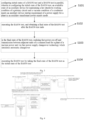
- the electrical power supply changeover method of the prior art is shown in Fig. 1 .
- the BAS54 test in the prior art is carried out when the reactor is under thermal shutdown condition, the 500kv ultra-high voltage power supply switch is switched off to trigger automatic switching action of the auxiliary standby transformer, and the power supply for a plant starts the devices, such as RCP001PO, RCP001PO, CRF001PO, CEX001PO, SEN, SRI, CVI, CET, GGR, GHE, in the auxiliary standby transformer supply mode.
- the test process involves a large number of network-related device operations, the test window requirements are strict, and the requirements to the test operation accuracy and effectiveness are quite high. Because of the complexity of the test operation, the test risk increases, and the test process needs a lot of manpower.
- the power supply distribution of auxiliary loads for maintaining primary circuit thermal shutdown and condenser vacuum conditions in a nuclear power plant is shown in Fig. 2 .
- one object of the present invention is to provide an electrical power supply changeover test method, apparatus and device for nuclear power plant.
- an electrical power supply changeover test method for a nuclear plant includes the steps of:
- the step of executing the BAS56 test includes the steps of:
- the step of realizing fast power cut-off and transmission between adjacent units of a common load for a plant of a nuclear power unit via fast power supply changeover technology which simulates automatic changeover includes the steps of:
- the step of executing the BAS54 test includes the steps of:
- the electrical power supply changeover test method further includes:
- the electrical power supply changeover test method further includes: keeping LHP and LHQ emergency diesel generator in a hot standby state in initial state of the test, to ensure that when the power supply for a plant fails to switch to auxiliary standby transformer, LHP/LHQ emergency automatically start to power the main pump shaft seal and heat shield related devices.
- the status of the unit is controlled via the steps of:
- the status of the unit is controlled via the steps of:
- the status of the unit is controlled via the steps of:
- the status of the unit is controlled via the steps of:
- the status of the unit is controlled via the steps of:
- the unit when LHA/LHB fail to switch to LHP/LHQ, the unit enters a SBO working condition and the unit status of the unit is controlled via the steps of:
- the electrical power supply changeover test method further includes simulating loss of main power supply outside the plant when BAS56 and Bas54 cannot be executed under a same task window, wherein the step of simulating loss of main power supply outside the plant includes the steps of:
- Yet another embodiment of the present invention also provides an electrical power supply changeover test device for a nuclear power plant including a memory having a computer program stored therein and a processor, wherein the computer program can be executed by the processor to implement the electrical power supply changeover test method for nuclear power plant of anyone of the present invention.
- the deep decoupling of an electrical power supply changeover test for a plant from a grid-related test can be realized, such that the degree of association between the electrical power supply changeover test for a plant and grid-related work is reduced, thereby realizing the high flexibility of a test window, and further improving the test efficiency, simplifying test operations, and reducing test risks.
- the investment in manpower, power consumption, diesel generator fuel consumption, desalination water production and process wastewater treatment is reduced, thereby saving more than 2 days of the main line period in the nuclear power unit commissioning start-up process hot state function test phase, which can remarkably reduce cost and increase efficiency.
- the embodiments of the present invention provides an electrical power supply changeover test method, apparatus and device for nuclear power plant, which can reduce the degree of association between the electrical power supply changeover test for a plant and grid-related work, realize decoupling of BAS54 test from a grid-related operation, improve flexibility of a test window, reduce test operation risk, improve the test efficiency, and reduce operation cost.
- a first embodiment of the present invention provides an electrical power supply changeover test method for a nuclear power plant, including the steps of:
- S104 executing the BAS54 test by taking the final state of the BAS56 test as the initial state of the BAS54 test.
- the step of executing the BAS54 test includes:
- the deep decoupling of an electrical power supply changeover test for a plant from a grid-related test can be realized, such that the degree of association between the electrical power supply changeover test for a plant and grid-related work is reduced, thereby realizing the high flexibility of a test window, and further improving the test efficiency, simplifying test operations, and reducing test risks.
- the investment in manpower, power consumption, diesel generator fuel consumption, desalination water production and process wastewater treatment is reduced, thereby saving more than 2 days of the main line period in the nuclear power unit commissioning start-up process hot state function test phase, which can remarkably reduce cost and increase efficiency.
- the adjustment of the test logic sequence also increases the risk concern during test execution.
- the 7LGI reverse operation is simplified, the test may still face a prolonged period of time, causing the primary circuit temperature to drop to a threshold. Therefore, manual intervention by the operator is required.
- a low-temperature emergency operation of primary circuit is described as following.
- the temperature of the primary circuit is raised appropriately before the start of the test, and the temperature of the primary circuit is closely monitored during the test.
- the RCP001PO is started by auxiliary standby transformer, to maintain the temperature of the primary circuit. If not feasible, GEV should be restored as soon as possible to power medium voltage distribution system, so that operators can manually start one or more main pumps via the main power supply to maintain the temperature and pressure of the primary circuit.
- one embodiment of the present invention also includes:
- a second embodiment of the present invention also provides an electrical power supply changeover test apparatus for a nuclear power plant including:
- the third embodiment of the present invention also provides an electrical power supply changeover test device for a nuclear power plant including a memory having a computer program stored therein and a processor, wherein the computer program can be executed by the processor to implement the electrical power supply changeover test method for nuclear power plant of the present invention as described above.
- each box in the block diagram and/or flowchart, and the combination of boxes in the block diagram and/or flowchart can be implemented with a dedicated hardware-based system that performs a given function or action, or can do it with a combination of specialized hardware and computer instructions.
- each functional module in each embodiment of the present invention can be integrated together to form an independent part.
- Each module can exist separatelly. It is also possible to integrate two or more modules to form an independent part.
- the computer software product is stored in a storage medium. A number of instructions are included to enable a computer device (which may be a personal computer, an electronic device, or a network device, etc.) to perform all or part of the steps of the method described in various embodiments of the present invention.
- the storage medium includes USB drives, removable hard drives, Read-Only Memory (ROM), Random-Access Memory (RAM) , diskettes or CDs, and a variety of other media that can store program code.
Landscapes
- Engineering & Computer Science (AREA)
- Physics & Mathematics (AREA)
- General Engineering & Computer Science (AREA)
- Plasma & Fusion (AREA)
- High Energy & Nuclear Physics (AREA)
- Business, Economics & Management (AREA)
- Emergency Management (AREA)
- Testing And Monitoring For Control Systems (AREA)
Abstract
Description
- The present invention generally relates to nuclear power plants and, more particularly, relates to an electrical power supply changeover test method, apparatus and device for a nuclear power plant.
- Under the condition the nuclear power plant lose normal power outside the plant, in order to restore the capability of forced circulation of the primary circuit and the core heat export, the reactor coolant pump needs to be started by auxiliary standby transformer power supply. Therefore, the nuclear power plant is provided with a reactor coolant pump, to realize the verification of power supply capability of auxiliary standby transformer to maintain the heat shutdown condition of primary circuit and the vacuum condition of condenser via the start-up test of the auxiliary step-down transformer (hereinafter referred as BAS54). When the reactor is under a thermal shutdown condition, the test is used to maintain the hot shutdown condition of the primary circuit and the vacuum condition of the condenser by starting auxiliary devices such as RCP001PO, CRF001PO, CEX001PO, SEN, SRI, CVI, CET, GGR, and GHE.
- In order to avoid a low temperature of the primary circuit caused by the loss of the reactor coolant pump for a long time due to the long period of the power changeover test during the hot state function test phase, BAS56 and BAS54 in the power supply changeover test in the hot state function test phase in the prior art are tested twice. After the BAS56 test is completed, it is necessary to restart three main coolant pumps to heat the working fluid of the primary circuit, so that the Bas54 test can be carried out after the reactor has been brought back to the standard thermal shutdown condition. The period of single test is shortened by means of staged tests, to realize the temperature control of the primary circuit finally. The electrical power supply changeover method of the prior art is shown in
Fig. 1 . - The BAS54 test in the prior art is carried out when the reactor is under thermal shutdown condition, the 500kv ultra-high voltage power supply switch is switched off to trigger automatic switching action of the auxiliary standby transformer, and the power supply for a plant starts the devices, such as RCP001PO, RCP001PO, CRF001PO, CEX001PO, SEN, SRI, CVI, CET, GGR, GHE, in the auxiliary standby transformer supply mode. Because the test process involves a large number of network-related device operations, the test window requirements are strict, and the requirements to the test operation accuracy and effectiveness are quite high. Because of the complexity of the test operation, the test risk increases, and the test process needs a lot of manpower. The power supply distribution of auxiliary loads for maintaining primary circuit thermal shutdown and condenser vacuum conditions in a nuclear power plant is shown in
Fig. 2 . - The conventional electrical power changeover test method in the hot-state function test phase of the prior art has the following disadvantages:
- 1) The flexibility and continuity of the test operation window are poor. The test method involves the operation of power grid device. Due to the restriction of the power grid operation, the flexibility of the test execution window is poor. At the same time, the continuous working condition of the test method is poor, which is not conducive to the main line duration control of the thermal function test.
- 2) The cost of the electrical power consumption, desalination water production and wastewater treatment during commissioning is increased.
- 3) The fuel consumption of the diesel generator is increased: before BAS56 and BAS54 tests are coupled, two 6,000kw emergency diesel generator need to be activated in both tests, which will increase diesel generator fuel consumption.
- 4) The number of test impact of the electrical device and process device is increased, which will increase the loss of industrial device.
- 5) The number of impact of the main pump and the circulating pump due to loss of the auxiliary system under the transient switching of electrical power supply is increased.
- 6) The risk of misoperation is increased. The restoration operation of the additional power supply outside the plant, the power distribution system for a plant, the plant load, and the re-uplink of the unit, involves more systems to be restored. There is a risk of human error operation.
- 7) Labor cost is increased. The re-uplink of the unit involves more than 50 systems of the process, electrical and instrumentation to be restored. Considering the configuration of at least 2 people for each system, after the test coupling, about 200 labor days of labor costs can be saved.
- In view of the foregoing, one object of the present invention is to provide an electrical power supply changeover test method, apparatus and device for nuclear power plant.
- According to one embodiment of the present invention, an electrical power supply changeover test method for a nuclear plant includes the steps of:
- configuring initial states of a BAS56 test and a BAS54 test in parallel, wherein in configuring the initial state of the BAS54 test, an available state of an auxiliary device for maintaining a hot shutdown working condition of a primary circuit and a vacuum condition of a condenser meets an auxiliary device startup requirement of a power supply for a plant in an auxiliary standby transformer power supply mode;
- executing the BAS56 test, and obtaining a final state of the BAS56 test after the BAS56 test ends;
- in the final state of the BAS56 test, realizing fast power cut-off and transmission between adjacent units of a common load for a plant of a nuclear power unit via fast power supply changeover technology which simulates automatic changeover; and
- executing the BAS54 test by taking the final state of the BAS56 test as the initial state of the BAS54 test.
- According to one aspect of the present invention, the step of executing the BAS56 test includes the steps of:
- disconnecting a 500kV ultra-high voltage switch of a normal power supply outside the plant;
- starting GPA protection action, to switch the power supply for a plant to auxiliary standby transformer power supply automatically;
- restoring the 500kV ultra-high voltage switch of the normal power supply outside the plant, restoring operation of the main transformer, and resetting the GPA protection; and
- completing the BAS56 test.
- According to one aspect of the present invention, for a public distribution panel 7LGI of the unit, the step of realizing fast power cut-off and transmission between adjacent units of a common load for a plant of a nuclear power unit via fast power supply changeover technology which simulates automatic changeover, includes the steps of:
- confirming that downstream medium voltage rotating load of 7LGI power supply has been stopped;
- using a test box to verify 7LGIB001 JA test bit opening and closing operation;
- putting 7LGIB001JA in working position and preparing for fast power supply changeover operation;
- disconnecting 7LGIA001JA and confirming electricity loss of 7LGI, closing 7LGIB001JA on site after a preset time, 7LGI reversing power to a LGC power supply of a adjacent unit for operation, wherein when 7LGIB001JA is not closed successfully, 7LGI fails to be switched to LGC power supply of an adjacent unit, the 7LGIA001JA switch has been disconnected and placed in an isolated position, to disconnect the DC power supply of the 7LGIA001JA switch and execute operation of powering 7LGI by 7LGIB;
- restoring the downstream medium voltage rotating load of 7LGI power.
- According to one aspect of the present invention, the step of executing the BAS54 test includes the steps of:
- operating LGA/D switch to auxiliary transformer power supply for operation, and starting a primary circuit device and a second circuit device in turn;
- switching power supply for a plant back to auxiliary normal transformer power supply, restoring plant electrical devices, and restoring the unit to a thermoelectric shutdown state; and
- completing the BAS54 test.
- According to one aspect of the present invention, the electrical power supply changeover test method further includes:
- when temperature of the primary circuit drops to a warning value, activating RCP001PO via an auxiliary standby transformer to maintain the temperature of the primary circuit; and
- if not feasible, restoring GEV to power medium voltage distribution system, so that operators can start one or more main pumps via a main power supply to maintain temperature and pressure of the primary circuit.
- According to one aspect of the present invention, the electrical power supply changeover test method further includes:
keeping LHP and LHQ emergency diesel generator in a hot standby state in initial state of the test, to ensure that when the power supply for a plant fails to switch to auxiliary standby transformer, LHP/LHQ emergency automatically start to power the main pump shaft seal and heat shield related devices. - According to one aspect of the present invention, when LGB fails to switch to the auxiliary standby transformer, the status of the unit is controlled via the steps of:
- checking to confirm that LHA is powered by LHP emergency diesel generator for operation;
- checking to confirm that RCV/RRI/SEC continue to run;
- performing RCV and ASG regulation operation, to stabilize the temperature and the pressure of the primary circuit;
- restoring LGB to be powered by auxiliary standby transformer;
- restoring GEW/GEV power supply;
- restoring power supply for a plant to be powered by normal power supply;
- reconfiguring test conditions in accordance with the initial state to re-execute the test.
- According to one aspect of the present invention, when LGC fails to switch to the auxiliary standby transformer, the status of the unit is controlled via the steps of:
- checking to confirm that LHB is powered by LHQ emergency diesel generator;
- checking to confirm that RCV/RRI/SEC continues to run;
- performing RCV and ASG regulation operation, to stabilize the temperature and the pressure of the primary circuit;
- restoring LGC to be powered by auxiliary standby transformer;
- restoring GEW/GEV power supply;
- restore power supply for a plant to be powered by normal power supply;
- reconfiguring test conditions in accordance with the initial state to re-execute the test.
- According to one aspect of the present invention, when LGB/LGC fails to switch to the auxiliary standby transformer, the status of the unit is controlled via the steps of:
- checking to confirm that LHA is powered by a LHP emergency diesel generator;
- checking to confirm that LHB is powered by a LHQ emergency diesel generator;
- checking to confirm that RCV/RRI/SEC continues to run;
- performing RCV and ASG regulation operation, to stabilize the temperature and the pressure of the primary circuit;
- restoring LGB to be powered by auxiliary standby transformer;
- restoring LGC to be powered by auxiliary standby transformer;
- restoring GEW/GEV power supply;
- restoring power supply for a plant to be powered by normal power supply;
- reconfiguring test conditions in accordance with the initial state to re-execute the test.
- According to one aspect of the present invention, when LHA fails to switch to LHP, the status of the unit is controlled via the steps of:
- checking to confirm that LHB is powered by LHQ emergency diesel generator;
- checking to confirm that RCV/RRI/SEC continues to run;
- performing RCV and ASG regulation operation, to stabilize the temperature and the pressure of the primary circuit;
- restoring LGB to be powered by auxiliary standby transformer;
- restoring GEW/GEV power supply;
- restoring power supply for a plant to be powered by normal power supply;
- reconfiguring test conditions in accordance with the initial state to re-execute the test.
- According to one aspect of the present invention, when LHB fails to switch to LHQ, the status of the unit is controlled via the steps of:
- checking to confirm that LHA is powered by LHP emergency diesel generator;
- checking to confirm that RCV/RRI/SEC continues to run;
- performing RCV and ASG regulation operation, to stabilize the temperature and the pressure of the primary circuit;
- restoring LGC to be powered by auxiliary standby transformer;
- restoring GEW/GEV power supply;
- restoring power supply for a plant to be powered by normal power supply;
- reconfiguring test conditions in accordance with the initial state to re-execute the test.
- According to one aspect of the present invention, when LHA/LHB fail to switch to LHP/LHQ, the unit enters a SBO working condition and the unit status of the unit is controlled via the steps of:
- configuring RRI/SEC in two columns to run before the test, and putting standby functions between the columns into operation;
- recording status of RCV device;
- restoring LGB/LHA to be powered by auxiliary standby transformer, or restoring LGC/LHB to be powered by auxiliary standby transformer;
- checking to confirm that RCV/RRI/SEC continues to run, otherwise starting manually;
- checking seal injection flow of RCP pump, wherein if the main pump shaft seal water is not established within 2 min, do not establish shaft seal water;
- performing RCV and ASG regulation operation, to stabilize the temperature and the pressure of the primary circuit;
- continuing to restore other power supply series to be powered by auxiliary standby transformer;
- restoring power supply for a plant to be powered by normal power supply;
- reconfiguring test conditions in accordance with the initial state to re-execute the test.
- According to one aspect of the present invention, the electrical power supply changeover test method further includes simulating loss of main power supply outside the plant when BAS56 and Bas54 cannot be executed under a same task window, wherein the step of simulating loss of main power supply outside the plant includes the steps of:
- disconnecting LGE001JA, LGF001JA via a main control room DCS under a hot shutdown working condition of the primary circuit of the unit;
- after disconnecting LGE001JA, LGF001JA, the main control room DCS disconnecting LGA001JA and LGD001JA synchronously to trigger LGB/C switch to auxiliary standby transformer power supply automatically and synchronously;
- continuing BAS54 test in auxiliary standby transformer power supply mode, and starting RCP001PO, CRF001PO , CEX001PO , SEN , SRI , CVI , CET , GGR , GHE auxiliary devices to maintain a hot shutdown working condition of the primary circuit and the vacuum condition of a condenser.
- Another embodiment of the present invention provides an electrical power supply changeover test apparatus for a nuclear plant including:
- a configuration unit, for configuring initial states of a BAS56 test and a BAS54 test in parallel, wherein in configuring the initial state of the BAS54 test, an available state of an auxiliary device for maintaining a hot shutdown working condition of a primary circuit and a vacuum condition of a condenser meets an auxiliary device startup requirement of a power supply for a plant in an auxiliary standby transformer power supply mode;
- a BAS56 test unit, for executing the BAS56 test, and obtaining a final state of the BAS56 test after the BAS56 test ends;
- a fast power supply changeover unit, for realizing fast power cut-off and transmission between adjacent units of a common load for a plant of a nuclear power unit via fast power supply changeover technology which simulates automatic changeover in the final state of the BAS56 test;
- a BAS54 test unit, for executing the BAS54 test by taking the final state of the BAS56 test as the initial state of the BAS54 test.
- Yet another embodiment of the present invention also provides an electrical power supply changeover test device for a nuclear power plant including a memory having a computer program stored therein and a processor, wherein the computer program can be executed by the processor to implement the electrical power supply changeover test method for nuclear power plant of anyone of the present invention.
- According to the embodiments of the present invention, the deep decoupling of an electrical power supply changeover test for a plant from a grid-related test can be realized, such that the degree of association between the electrical power supply changeover test for a plant and grid-related work is reduced, thereby realizing the high flexibility of a test window, and further improving the test efficiency, simplifying test operations, and reducing test risks. The investment in manpower, power consumption, diesel generator fuel consumption, desalination water production and process wastewater treatment is reduced, thereby saving more than 2 days of the main line period in the nuclear power unit commissioning start-up process hot state function test phase, which can remarkably reduce cost and increase efficiency.
- In order to explain the technical solution of the embodiments of the present invention more clearly, the attached drawings which are used in the embodiments of the present invention will briefly described below. It should be understood that, only some embodiments of the present invention are shown in the attached drawings. Therefore, the drawings should not be seen as a limitation of scope of the present invention. For one ordinary skilled in the art, other relevant drawings can also be obtained without creative work based on these drawings.
-
Fig. 1 is a flow chart of an electrical power supply changeover test method for a nuclear power plant in the prior art; -
Fig. 2 is a schematic diagram of auxiliary load distribution for a prior nuclear power plant, to maintain a hot shutdown working condition and a vacuum condition of a condenser; -
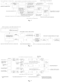
Fig. 3 is a flowchart of an electrical power supply changeover test method for a nuclear power plant according to a first embodiment of the present invention; -
Fig. 4 is another flowchart of an electrical power supply changeover test method for a nuclear power plant according to a first embodiment of the present invention; -
Fig. 5 is a schematic flow diagram of a fast power supply changeover method for 7LGI which simulates automatic changeover; -
Fig. 6 is a flow diagram of an emergency response plan for a low-temperature primary circuit; -
Fig. 7 is a schematic diagram of a processing method when the electrical power supply changeover fails; -
Fig. 8 is a flow diagram for simulating the loss of main power supply outside the plant; and -
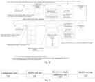
Fig. 9 is a structure schematic diagram of an electrical power supply changeover test apparatus for a nuclear power plant according to a second embodiment of the present invention. - In order to make the objects, technical solution and advantages of the embodiments of the present invention clearer, the technical solutions of the present invention will be described clearly and completely in the following in view of the attached drawings. It should be understood that, the embodiments described as following are only part of the embodiments of the present invention, not all embodiments of the present invention. Based on the embodiments of the present invention, all other embodiments can also be obtained by one ordinary skilled in the art without creative work. These embodiments all fall within the scope of protection of the present invention. Therefore, the following detailed description of the embodiments of the present invention provided in the attached drawings is not intended to limit the scope of the present invention, but merely represent selected embodiments of the present invention. Based on the embodiments of the present invention, all other embodiments obtained by one ordinary skilled in the art without creative work, also fall within the scope of the present invention.
- The embodiments of the present invention provides an electrical power supply changeover test method, apparatus and device for nuclear power plant, which can reduce the degree of association between the electrical power supply changeover test for a plant and grid-related work, realize decoupling of BAS54 test from a grid-related operation, improve flexibility of a test window, reduce test operation risk, improve the test efficiency, and reduce operation cost.
- In particular, since it takes less than 1.5 seconds for the residual voltage U of LGB/C to drop to 0.4un when switching between auxiliary normal transformer and auxiliary standby transformer in the BAS56 test, it should be put into operation as much as possible before the test, to test the project in extreme cases. In BAS56 test, public distribution panel 7LGI of the unit is powered by the test unit. However, in BAS54 test, due to the power supply mode of auxiliary standby transformer, when the main pump needs to be started by auxiliary standby transformer, 7LGI should be switched to adjacent units for power supply. After the power supply for the plant is switched to auxiliary standby transformer power supply in the hot test stage, because the core has no residual heat, the core loses heat source after the main pump is shut down. In addition, due to the natural cooling of the primary circuit, the temperature and the pressure of the primary circuit will slowly decrease. In serious cases, the temperature and the pressure of the primary circuit will go beyond the limit of the operating parameters, which leads to unexpected trigger of the reactor protection system. In accordance with normal operation of the power supply changeover mode, strict implementation of the operation and power transmission shutdown regulations are needed, which will last for a long time. In order to realize the coupling between BAS56 and BAS54, 7LGI must be switched to adjacent unit immediately for power supply after power supply for a plant is switched to auxiliary standby transformer power supply and the unit is in a steady state.
- In case that BAS56 and Bas54 execute under two task windows, to realize the deep decoupling between BAS54 and grid-related operation, the operating condition of nuclear power unit without main power supply outside the plant is simulated comprehensively, to start auxiliary devices, such as RCP001PO, CRF001PO, CEX001PO, SEN, SRI, CVI, CET, GGR, GHE in auxiliary standby transformer power supply mode, and maintain a hot shutdown working condition of the primary circuit and the vacuum condition of the condenser.
- In order to facilitate the understanding of the present invention, the present invention will be described in more detail below. Some terms in the present invention are described below.
- BAS--Electrical Power Supply Changeover Test
- ASG--Auxiliary Feedwater
- RCP--Reactor Cooling System
- RCV--Chemical and Volume Control
- RRI--Component Cooling
- SEC--Essential Service Water
- CRF --Circulating Water System
- CEX--Condensate Extraction System
- GGR--Turbine Lubrication, Jacking and Turning System
- GHE--Generator Seal Oil System
- CVI--Condenser Vacuum System
- SEN--Auxiliary Cooling Water System
- SRI--Conventional Island Closed Cooling Water System
- CET--Turbine Gland System
- GEV-Power Transmission System
- GEW--500kV ultra High Voltage Distribution System
- LGA, LGB, LGC, LGD, LGE, LGF--CI Medium-Voltage Normal Distribution System
- LGB001JA, LGC001JA --the Auxiliary Normal Transformer Power Side Tie Breaker of CI Medium-Voltage Normal Distribution System
- LGB102JA, LGC102JA--the Auxiliary Standby Transformer Power Side Incoming Breaker of CI Medium-Voltage Normal Distribution System
- 7LGJ--BOP Medium-Voltage Normal switchboard
- LHA, LHB--NI Medium-Voltage Distribution Board Emergency Power Supply System
- LHP--A Medium-Voltage AC Emergency Power Supply - Diesel - Train A
- LHQ--Medium-Voltage AC Emergency Power Supply - Diesel - Train B
- GPA--Generator and Power Transmission Protection System
- TS--Auxiliary Normal Transformer
- TA--Auxiliary Standby Transformer
- power supply for a plant including the Auxiliary Normal Power, the Auxiliary Standby Power and the Auxiliary Emergency Power
- DCS--Distributed Control System
- Referring to
Figs. 3 and 4 , a first embodiment of the present invention provides an electrical power supply changeover test method for a nuclear power plant, including the steps of: - S101: configuring initial states of a BAS56 test and a BAS54 test in parallel, wherein in configuring the initial state of the BAS54 test, an available state of an auxiliary device for maintaining a hot shutdown working condition of a primary circuit and a vacuum condition of a condenser meets an auxiliary device startup requirement of a power supply for a plant in an auxiliary standby transformer power supply mode.
- S102: executing the BAS56 test, and obtaining a final state of the BAS56 test after the BAS56 test ends;
- wherein the step of executing the BAS56 test includes the steps of:
- disconnecting a 500kV ultra-high voltage switch of a normal power supply outside the plant;
- starting GPA protection action, to switch the power supply for a plant to auxiliary standby transformer power supply automatically;
- restoring the 500kV ultra-high voltage switch of the normal power supply outside the plant, restoring operation of the main transformer, and resetting the GPA protection; and
- completing the BAS56 test.
- S103: in the final state of the BAS56 test, realizing fast power cut-off and transmission between adjacent units of a common load for a plant of a nuclear power unit via fast power supply changeover technology which simulates automatic changeover.
wherein, as shown inFig. 5 , for a public distribution panel 7LGI of the unit, the fast power supply changeover technology which simulates automatic changeover includes: - confirming that downstream medium voltage rotating load of 7LGI power supply has been stopped;
- using a test box to verify 7LGIB001JA test bit opening and closing operation;
- putting 7LGIB001JA in working position and preparing for fast power supply changeover operation;
- disconnecting 7LGIA001JA and confirming electricity loss of 7LGI, closing 7LGIB001JA on site after a preset time (such as 3 seconds), 7LGI reversing power to a LGC power supply of a adjacent unit for operation.
- In the present embodiment, when 7LGIB001JA is not closed successfully, 7LGI fails to be switched to LGC power supply of an adjacent unit, the 7LGIA001JA switch has been disconnected and placed in an isolated position, to disconnect the DC power supply of the 7LGIA001JA switch and execute operation of powering 7LGI by 7LGIB.
- The downstream medium voltage rotating load of 7LGI power is restored.
- S104: executing the BAS54 test by taking the final state of the BAS56 test as the initial state of the BAS54 test.
- In the present embodiment, the step of executing the BAS54 test includes:
- operating LGA/D switch to auxiliary standby transformer power supply for operation, and starting a primary circuit device and a second circuit device in turn;
- switching power supply for a plant back to auxiliary normal transformer power supply, restoring plant electrical devices, and restoring the unit to a thermoelectric shutdown state; and
- completing the BAS54 test.
- In view of the foregoing, According to the embodiments of the present invention, the deep decoupling of an electrical power supply changeover test for a plant from a grid-related test can be realized, such that the degree of association between the electrical power supply changeover test for a plant and grid-related work is reduced, thereby realizing the high flexibility of a test window, and further improving the test efficiency, simplifying test operations, and reducing test risks. The investment in manpower, power consumption, diesel generator fuel consumption, desalination water production and process wastewater treatment is reduced, thereby saving more than 2 days of the main line period in the nuclear power unit commissioning start-up process hot state function test phase, which can remarkably reduce cost and increase efficiency.
- To facilitate understanding of the present invention, some preferred embodiments of the present invention will be further described as following.
- In the above embodiments, the adjustment of the test logic sequence also increases the risk concern during test execution. Although the 7LGI reverse operation is simplified, the test may still face a prolonged period of time, causing the primary circuit temperature to drop to a threshold. Therefore, manual intervention by the operator is required. In a preferred embodiment, as shown in
Fig. 6 , a low-temperature emergency operation of primary circuit is described as following. - The temperature of the primary circuit is raised appropriately before the start of the test, and the temperature of the primary circuit is closely monitored during the test. When the temperature of the primary circuit drops to a warning value, to prevent the temperature of the primary circuit from further dropping, the RCP001PO is started by auxiliary standby transformer, to maintain the temperature of the primary circuit. If not feasible, GEV should be restored as soon as possible to power medium voltage distribution system, so that operators can manually start one or more main pumps via the main power supply to maintain the temperature and pressure of the primary circuit.
- In order to keep the shaft seal and heat shield of the main pump from being lost, as shown in
Fig. 7 , one embodiment of the present invention also includes: - keeping LHP and LHQ emergency diesel generator in a hot standby state in initial state of the test, to ensure that when the power supply for a plant fails to switch to auxiliary standby transformer, LHP/LHQ emergency automatically start to power the main pump shaft seal and heat shield related devices.
- wherein when LGB fails to switch to the auxiliary standby transformer, the status of the unit is controlled via the steps of:
- checking to confirm that LHA is powered by LHP emergency diesel generator for operation;
- checking to confirm that RCV/RRI/SEC continue to run;
- performing RCV and ASG regulation operation, to stabilize the temperature and the pressure of the primary circuit;
- restoring LGB to be powered by auxiliary standby transformer;
- restoring GEW/GEV power supply;
- restoring power supply for a plant to be powered by normal power supply;
- reconfiguring test conditions in accordance with the initial state to re-execute the test.
- wherein when LGC fails to switch to the auxiliary standby transformer, the status of the unit is controlled via the steps of:
- checking to confirm that LHB is powered by LHQ emergency diesel generator;
- checking to confirm that RCV/RRI/SEC continues to run;
- performing RCV and ASG regulation operation, to stabilize the temperature and the pressure of the primary circuit;
- restoring LGC to be powered by auxiliary standby transformer;
- restoring GEW/GEV power supply;
- restore power supply for a plant to be powered by normal power supply;
- reconfiguring test conditions in accordance with the initial state to re-execute the test.
- wherein when LGB/LGC fail to switch to the auxiliary standby transformer, the status of the unit is controlled via the steps of:
- checking to confirm that LHA is powered by a LHP emergency diesel generator;
- checking to confirm that LHB is powered by a LHQ emergency diesel generator;
- checking to confirm that RCV/RRI/SEC continues to run;
- performing RCV and ASG regulation operation, to stabilize the temperature and the pressure of the primary circuit;
- restoring LGB to be powered by auxiliary standby transformer;
- restoring LGC to be powered by auxiliary standby transformer;
- restoring GEW/GEV power supply;
- restoring power supply for a plant to be powered by normal power supply;
- reconfiguring test conditions in accordance with the initial state to re-execute the test.
- when LHA fails to switch to LHP, the status of the unit is controlled via the steps of:
- checking to confirm that LHB is powered by LHQ emergency diesel generator;
- checking to confirm that RCV/RRI/SEC continues to run;
- performing RCV and ASG regulation operation, to stabilize the temperature and the pressure of the primary circuit;
- restoring LGB to be powered by auxiliary standby transformer;
- restoring GEW/GEV power supply;
- restoring power supply for a plant to be powered by normal power supply;
- reconfiguring test conditions in accordance with the initial state to re-execute the test.
- wherein when LHB fails to switch to LHQ, the status of the unit is controlled via the steps of:
- checking to confirm that LHA is powered by LHP emergency diesel generator;
- checking to confirm that RCV/RRI/SEC continues to run;
- performing RCV and ASG regulation operation, to stabilize the temperature and the pressure of the primary circuit;
- restoring LGC to be powered by auxiliary standby transformer;
- restoring GEW/GEV power supply;
- restoring power supply for a plant to be powered by normal power supply;
- reconfiguring test conditions in accordance with the initial state to re-execute the test.
- wherein when LHA/LHB fail to switch to LHP/LHQ, the unit enters a SBO working condition and the unit status of the unit is controlled via the steps of:
- configuring RRI/SEC in two columns to run before the test, and putting standby functions between the columns into operation;
- recording status of RCV device;
- restoring LGB/LHA to be powered by auxiliary standby transformer, or restoring LGC/LHB to be powered by auxiliary standby transformer;
- checking to confirm that RCV/RRI/SEC continues to run, otherwise starting manually;
- checking seal injection flow of RCP pump, wherein if the main pump shaft seal water is not established within 2 min, do not establish shaft seal water;
- performing RCV and ASG regulation operation, to stabilize the temperature and the pressure of the primary circuit;
- continuing to restore other power supply series to be powered by auxiliary standby transformer;
- restoring power supply for a plant to be powered by normal power supply;
- reconfiguring test conditions in accordance with the initial state to re-execute the test.
- when BAS56 and Bas54 cannot be executed under a same task window, the electrical power supply changeover test method further includes simulating loss of main power supply outside the plant, to reduce the degree of association between the BAS54 test and grid-related work, and realize decoupling of BAS54 test from a grid-related operation. As shown in
Fig. 8 , the step of simulating loss of main power supply outside the plant includes:- disconnecting LGE001JA, LGF001JA via a main control room DCS under a hot shutdown working condition of the primary circuit of the unit;
- after disconnecting LGE001JA, LGF001JA, the main control room DCS disconnecting LGA001JA and LGD001JA synchronously to trigger LGB/C switch to auxiliary standby transformer power supply automatically and synchronously;
- continuing BAS54 test in auxiliary standby transformer power supply mode, and starting RCP001PO, CRF001PO , CEX001PO , SEN , SRI , CVI , CET , GGR , GHE auxiliary devices to maintain a hot shutdown working condition of the primary circuit and the vacuum condition of a condenser.
- Referring to
Fig. 9 , a second embodiment of the present invention also provides an electrical power supply changeover test apparatus for a nuclear power plant including: - a
configuration unit 210, for configuring initial states of a BAS56 test and a BAS54 test in parallel, wherein in configuring the initial state of the BAS54 test, an available state of an auxiliary device for maintaining a hot shutdown working condition of a primary circuit and a vacuum condition of a condenser meets an auxiliary device startup requirement of a power supply for a plant in an auxiliary standby transformer power supply mode; - a
BAS56 test unit 220, for executing the BAS56 test, and obtaining a final state of the BAS56 test after the BAS56 test ends; - a fast power
supply changeover unit 230, for realizing fast power cut-off and transmission between adjacent units of a common load for a plant of a nuclear power unit via fast power supply changeover technology which simulates automatic changeover in the final state of the BAS56 test; and - a BAS54 test unit 240, for executing the BAS54 test by taking the final state of the BAS56 test as the initial state of the BAS54 test.
- The third embodiment of the present invention also provides an electrical power supply changeover test device for a nuclear power plant including a memory having a computer program stored therein and a processor, wherein the computer program can be executed by the processor to implement the electrical power supply changeover test method for nuclear power plant of the present invention as described above.
- In the embodiments provided in the present invention, it should be understood that the device and method as disclosed can be realized in other ways. The apparatus and method embodiments described above are only illustrative, for example, the flowcharts and block diagrams in the drawings show possible architectures, functions, and operations of devices, methods, and computer program products according to embodiments of the present invention. Each box in a flowchart or block diagram can represent a module, program segment, or part of code, the module, the program segment, or a part of code contains one or more executable instructions for implementing a specified logical function. It should also be noted that, in alternative implementations of the present invention, the functions noted in the box can also occur in a different order than those noted in the attached drawings. For example, two contiguous boxes actually be executed in essentially parallel, can sometimes be executed in the opposite order, depending on the functionality involved. It should be also noted that each box in the block diagram and/or flowchart, and the combination of boxes in the block diagram and/or flowchart, can be implemented with a dedicated hardware-based system that performs a given function or action, or can do it with a combination of specialized hardware and computer instructions.
- In addition, each functional module in each embodiment of the present invention can be integrated together to form an independent part. Each module can exist separatelly. It is also possible to integrate two or more modules to form an independent part.
- The functions, if implemented in the form of software function modules and sold or used as stand-alone products, can be stored in a computer-readable storage medium. Therefore, the technical solution of the present invention can be embodied in the form of a software product in essence or a portion that contributes to the prior art or a portion of the technical solution. The computer software product is stored in a storage medium. A number of instructions are included to enable a computer device (which may be a personal computer, an electronic device, or a network device, etc.) to perform all or part of the steps of the method described in various embodiments of the present invention. The storage medium includes USB drives, removable hard drives, Read-Only Memory (ROM), Random-Access Memory (RAM) , diskettes or CDs, and a variety of other media that can store program code.
- It should be noted that, in the description, the terms "include", "comprise" or any other variant thereof are intended to cover non-exclusive inclusion, so that a process, method, article, or device including a set of elements includes not only those elements but also other elements not explicitly listed. It may include elements inherent in such a process, method, article, or device. In the absence of any further restrictions, elements defined by the statement "including a..." do not exclude the existence of additional elements of the same in the process, method, object, or device that includes the elements.
- The above described embodiments are only preferred embodiments of the present invention, and are not intended to limit the scope of the present invention. Any modification, equivalent replacement and improvement within the spirit and principle of the present invention should be included in the protection scope of the present invention.
Claims (15)
- An electrical power supply changeover test method for a nuclear plant, characterized in that the electrical power supply changeover test method for a nuclear plant comprises the steps of:(S101) configuring initial states of a BAS56 test and a BAS54 test in parallel, wherein in configuring the initial state of the BAS54 test, an available state of an auxiliary device for maintaining a hot shutdown working condition of a primary circuit and a vacuum condition of a condenser meets an auxiliary device startup requirement of a power supply for a plant in an auxiliary standby transformer power supply mode;(S102) executing the BAS56 test, and obtaining a final state of the BAS56 test after the BAS56 test ends;(S103) in the final state of the BAS56 test, realizing fast power cut-off and transmission between adjacent units of a common load for a plant of a nuclear power unit via fast power supply changeover technology which simulates automatic changeover; and(S104) executing the BAS54 test by taking the final state of the BAS56 test as the initial state of the BAS54 test.
- The electrical power supply changeover test method of claim 1, characterized in that, the step of executing the BAS56 test comprises:disconnecting a 500kV ultra-high voltage switch of a normal power supply outside the plant;starting GPA protection action, to switch the power supply for a plant to auxiliary standby transformer power supply automatically;restoring the 500kV ultra-high voltage switch of the normal power supply outside the plant, restoring operation of the main transformer, and resetting the GPA protection; andcompleting the BAS56 test.
- The electrical power supply changeover test method of claim 1, characterized in that, for a public distribution panel 7LGI of the unit, the step of realizing fast power cut-off and transmission between adjacent units of a common load for a plant of a nuclear power unit via fast power supply changeover technology which simulates automatic changeover, comprises:confirming that downstream medium voltage rotating load of 7LGI power supply has been stopped;using a test box to verify 7LGIB001JA test bit opening and closing operation;putting 7LGIB001JA in working position and preparing for fast power supply changeover operation;disconnecting 7LGIA001JA and confirming electricity loss of 7LGI, closing 7LGIB001JA on the spot after a preset time, 7LGI reversing power to a LGC power supply of an adjacent unit for operation, wherein when 7LGIB001JA is not closed successfully, 7LGI fails to be switched to LGC power supply of an adjacent unit, the 7LGIA001JA switch has been disconnected and placed in an isolated position, to disconnect the DC power supply of the 7LGIA001JA switch and execute operation of powering 7LGI by 7LGIB;restoring the downstream medium voltage rotating load of 7LGI power.
- The electrical power supply changeover test method of claim 1, characterized in that, the step of executing the BAS54 test comprises:operating LGA/D switch to auxiliary standby transformer power supply for operation, and starting a primary circuit device and a second circuit device in turn;switching power supply for a plant back to auxiliary normal transformer power supply, restoring plant electrical devices, and restoring the unit to a thermoelectric shutdown state; andcompleting the BAS54 test.
- The electrical power supply changeover test method of claim 1, characterized in that, the electrical power supply changeover test method further comprises:when temperature of the primary circuit drops to a warning value, activating RCP001PO via an auxiliary standby transformer to maintain the temperature of the primary circuit; andif not feasible, restoring GEV to power medium voltage distribution system, so that operators can start one or more main pumps via a main power supply to maintain temperature and pressure of the primary circuit.
- The electrical power supply changeover test method of claim 1, characterized in that, the electrical power supply changeover test method further comprises:
keeping LHP and LHQ emergency diesel generator in a hot standby state in initial state of the test, to ensure that when the power supply for a plant fails to switch to auxiliary standby transformer, LHP/LHQ emergency automatically start to power the main pump shaft seal and heat shield related devices. - The electrical power supply changeover test method of claim 6, characterized in that, when LGB fails to switch to the auxiliary standby transformer, the status of the unit is controlled via the steps of:checking to confirm that LHA is powered by LHP emergency diesel generator for operation;checking to confirm that RCV/RRI/SEC continue to run;performing RCV and ASG regulation operation, to stabilize the temperature and the pressure of the primary circuit;restoring LGB to be powered by auxiliary standby transformer;restoring GEW/GEV power supply;restoring power supply for a plant to be powered by normal power supply;reconfiguring test conditions in accordance with the initial state to re-execute the test.
- The electrical power supply changeover test method of claim 6, characterized in that, when LGC fails to switch to the auxiliary standby transformer, the status of the unit is controlled via the steps of:checking to confirm that LHB is powered by LHQ emergency diesel generator;checking to confirm that RCV/RRI/SEC continues to run;performing RCV and ASG regulation operation, to stabilize the temperature and the pressure of the primary circuit;restoring LGC to be powered by auxiliary standby transformer;restoring GEW/GEV power supply;restore power supply for a plant to be powered by normal power supply;reconfiguring test conditions in accordance with the initial state to re-execute the test.
- The electrical power supply changeover test method of claim 6, characterized in that, when LGB/LGC fail to switch to the auxiliary standby transformer, the status of the unit is controlled via the steps of:checking to confirm that LHA is powered by a LHP emergency diesel generator;checking to confirm that LHB is powered by a LHQ emergency diesel generator;checking to confirm that RCV/RRI/SEC continues to run;performing RCV and ASG regulation operation, to stabilize the temperature and the pressure of the primary circuit;restoring LGB to be powered by auxiliary standby transformer;restoring LGC to be powered by auxiliary standby transformer;restoring GEW/GEV power supply;restoring power supply for a plant to be powered by normal power supply;reconfiguring test conditions in accordance with the initial state to re-execute the test.
- The electrical power supply changeover test method of claim 6, characterized in that, when LHA fails to switch to LHP, the status of the unit is controlled via the steps of:checking to confirm that LHB is powered by LHQ emergency diesel generator;checking to confirm that RCV/RRI/SEC continues to run;performing RCV and ASG regulation operation, to stabilize the temperature and the pressure of the primary circuit;restoring LGB to be powered by auxiliary standby transformer;restoring GEW/GEV power supply;restoring power supply for a plant to be powered by normal power supply;reconfiguring test conditions in accordance with the initial state to re-execute the test.
- The electrical power supply changeover test method of claim 6, characterized in that, when LHB fails to switch to LHQ, the status of the unit is controlled via the steps of:checking to confirm that LHA is powered by LHP emergency diesel generator;checking to confirm that RCV/RRI/SEC continues to run;performing RCV and ASG regulation operation, to stabilize the temperature and the pressure of the primary circuit;restoring LGC to be powered by auxiliary standby transformer;restoring GEW/GEV power supply;restoring power supply for a plant to be powered by normal power supply;reconfiguring test conditions in accordance with the initial state to re-execute the test.
- The electrical power supply changeover test method of claim 6, characterized in that, when LHA/LHB fail to switch to LHP/LHQ, the unit enters a SBO working condition and the unit status of the unit is controlled via the steps of:configuring RRI/SEC in two columns to run before the test, and putting standby functions between the columns into operation;recording status of RCV device;restoring LGB/LHA to be powered by auxiliary standby transformer, or restoring LGC/LHB to be powered by auxiliary standby transformer;checking to confirm that RCV/RRI/SEC continues to run, otherwise starting manually;checking seal injection flow of RCP pump, wherein if the main pump shaft seal water is not established within 2 min, do not establish shaft seal water;performing RCV and ASG regulation operation, to stabilize the temperature and the pressure of the primary circuit;continuing to restore other power supply series to be powered by auxiliary standby transformer;restoring power supply for a plant to be powered by normal power supply;reconfiguring test conditions in accordance with the initial state to re-execute the test.
- The electrical power supply changeover test method of claim 4, characterized in that, the electrical power supply changeover test method further comprises simulating loss of main power supply outside the plant when BAS56 and Bas54 cannot be executed under a same task window, wherein the step of simulating loss of main power supply outside the plant comprises:disconnecting LGE001JA, LGF001JA via a main control room DCS under a hot shutdown working condition of the primary circuit of the unit;after disconnecting LGE001JA, LGF001JA, the main control room DCS disconnecting LGA001JA and LGD001JA synchronously to trigger LGB/C switch to auxiliary standby transformer power supply automatically and synchronously;continuing BAS54 test in auxiliary standby transformer power supply mode, and starting RCP001PO, CRF001PO , CEX001PO , SEN , SRI , CVI , CET , GGR , GHE auxiliary devices to maintain a hot shutdown working condition of the primary circuit and the vacuum condition of a condenser.
- An electrical power supply changeover test apparatus, characterized in that, the electrical power supply changeover test apparatus comprises:a configuration unit (210), for configuring initial states of a BAS56 test and a BAS54 test in parallel, wherein in configuring the initial state of the BAS54 test, an available state of an auxiliary device for maintaining a hot shutdown working condition of a primary circuit and a vacuum condition of a condenser meets an auxiliary device startup requirement of a power supply for a plant in an auxiliary standby transformer power supply mode;a BAS56 test unit (220), for executing the BAS56 test, and obtaining a final state of the BAS56 test after the BAS56 test ends;a fast power supply changeover unit (230), for realizing fast power cut-off and transmission between adjacent units of a common load for a plant of a nuclear power unit via fast power supply changeover technology which simulates automatic changeover in the final state of the BAS56 test; anda BAS54 test unit (240), for executing the BAS54 test by taking the final state of the BAS56 test as the initial state of the BAS54 test.
- An electrical power supply changeover test device, characterized in that, the electrical power supply changeover test device comprises a memory having a computer program stored therein and a processor, wherein the computer program can be executed by the processor to implement the electrical power supply changeover test method for nuclear power plant of anyone of claims 1 to 13.
Applications Claiming Priority (2)
| Application Number | Priority Date | Filing Date | Title |
|---|---|---|---|
| CN202111208236.0A CN114121317B (en) | 2021-10-18 | 2021-10-18 | Test methods, apparatus and equipment for switching power supplies in nuclear power plants |
| PCT/CN2022/102852 WO2023065718A1 (en) | 2021-10-18 | 2022-06-30 | Electrical power supply changeover test method, apparatus and device for nuclear power plant |
Publications (2)
| Publication Number | Publication Date |
|---|---|
| EP4432304A1 true EP4432304A1 (en) | 2024-09-18 |
| EP4432304A4 EP4432304A4 (en) | 2025-09-10 |
Family
ID=80375917
Family Applications (1)
| Application Number | Title | Priority Date | Filing Date |
|---|---|---|---|
| EP22882340.7A Pending EP4432304A4 (en) | 2021-10-18 | 2022-06-30 | Method, apparatus and device for testing the power supply switchover for a nuclear power plant |
Country Status (3)
| Country | Link |
|---|---|
| EP (1) | EP4432304A4 (en) |
| CN (1) | CN114121317B (en) |
| WO (1) | WO2023065718A1 (en) |
Families Citing this family (3)
| Publication number | Priority date | Publication date | Assignee | Title |
|---|---|---|---|---|
| CN114121317B (en) * | 2021-10-18 | 2026-01-06 | 中广核工程有限公司 | Test methods, apparatus and equipment for switching power supplies in nuclear power plants |
| CN119253836A (en) * | 2024-07-24 | 2025-01-03 | 北京双杰电气股份有限公司 | Intelligent complete equipment inspection vehicle |
| CN120489458B (en) * | 2025-05-14 | 2025-12-16 | 振航电气科技有限公司 | Ring main unit intelligent detection equipment |
Family Cites Families (13)
| Publication number | Priority date | Publication date | Assignee | Title |
|---|---|---|---|---|
| JPH09292268A (en) * | 1996-04-26 | 1997-11-11 | Toshiba Corp | Instrument calibration test isolation device |
| CN102638095B (en) * | 2012-04-24 | 2015-09-23 | 中广核工程有限公司 | A kind of method of supplying power to of nuclear power plant cold-state function test |
| CN103514969B (en) * | 2012-06-28 | 2017-04-12 | 中国核电工程有限公司 | Power supply system failure and consequence analyzing method |
| WO2014187133A1 (en) * | 2013-05-22 | 2014-11-27 | 江苏省电力公司常州供电公司 | Intelligent checking system for backup power supply automatic switching apparatus |
| JP2016065834A (en) * | 2014-09-26 | 2016-04-28 | 株式会社日立製作所 | Emergency operation assist system for plants |
| CN104299661B (en) * | 2014-10-11 | 2017-05-03 | 中广核工程有限公司 | Transient test control method and system used in debugging and starting process of nuclear power station |
| CN104637558B (en) * | 2015-01-23 | 2017-04-26 | 福建省电力勘测设计院 | Safe and stable control method for asynchronous oscillation of nuclear power unit |
| CN105098968B (en) * | 2015-08-18 | 2018-03-09 | 中广核工程有限公司 | A kind of nuclear power plant's Primary hydraulic test dead electricity control method and system |
| CN105427911B (en) * | 2015-11-10 | 2017-07-11 | 中广核工程有限公司 | The control method and control system of PWR nuclear power plant service power switching tests |
| JP7169134B2 (en) * | 2018-09-07 | 2022-11-10 | 三菱重工業株式会社 | Nuclear reactor plant, operating method of nuclear reactor plant |
| CN109254250B (en) * | 2018-09-29 | 2021-04-13 | 中广核工程有限公司 | Experimental method of switching power supply for plant in the cold state function test stage of primary circuit of nuclear power plant |
| CN112185602B (en) * | 2020-09-15 | 2023-12-08 | 岭东核电有限公司 | Methods, devices, terminal equipment and storage media for nuclear power plant standby units |
| CN114121317B (en) * | 2021-10-18 | 2026-01-06 | 中广核工程有限公司 | Test methods, apparatus and equipment for switching power supplies in nuclear power plants |
-
2021
- 2021-10-18 CN CN202111208236.0A patent/CN114121317B/en active Active
-
2022
- 2022-06-30 EP EP22882340.7A patent/EP4432304A4/en active Pending
- 2022-06-30 WO PCT/CN2022/102852 patent/WO2023065718A1/en not_active Ceased
Also Published As
| Publication number | Publication date |
|---|---|
| CN114121317B (en) | 2026-01-06 |
| CN114121317A (en) | 2022-03-01 |
| EP4432304A4 (en) | 2025-09-10 |
| WO2023065718A1 (en) | 2023-04-27 |
Similar Documents
| Publication | Publication Date | Title |
|---|---|---|
| CN114121317B (en) | Test methods, apparatus and equipment for switching power supplies in nuclear power plants | |
| CN107069963B (en) | A kind of unattended hydropower plant intelligence prison disk method and system | |
| CN101430358A (en) | Head-machine first water pump behavior full-group start test method for pump storage plant | |
| CN102638095A (en) | Power supply method of cold-state function test in nuclear power plant | |
| BR102015026557A2 (en) | power generation system and method | |
| CN107465255A (en) | A kind of Turbo-generator Set accident starts auxiliary Power switching method and system | |
| CN106160202A (en) | The method of supplying power to of a kind of nuclear power plant Primary hydraulic test and system | |
| CN105098968B (en) | A kind of nuclear power plant's Primary hydraulic test dead electricity control method and system | |
| CN110597173B (en) | A kind of main transformer cooling control method | |
| CN102324757B (en) | Monitoring method and system of energy storage system of nuclear power station emergency power supply | |
| CN107528293A (en) | Unit fault processing method and device | |
| CN114019372B (en) | A method for checking the first loading capacity of emergency diesel generators in thermal power plants | |
| CN104237714B (en) | Overvoltage integrated monitoring fault diagnosing device and method for transformer substation | |
| CN206195453U (en) | Million units do not have high -pressure stand -by power supply's quick recovering start -up system | |
| CN106786617B (en) | A kind of motor low voltage protection method and device | |
| CN215256725U (en) | A highly reliable oil pump control system suitable for pumped storage power station | |
| CN207184153U (en) | A kind of dynamic communication ups system for black net thermal power plant load power supply | |
| CN117967649A (en) | An emergency DC power supply oil pump system for a small hydropower station speed regulator | |
| CN216312743U (en) | Security power supply system with outlet circuit breaker and double-gas turbine configuration | |
| CN116683402A (en) | A Method and Structure for Quickly Removing Excitation Transformation Faults of Self-Shunt Excited Generators | |
| CN119861605B (en) | A smart control method and system applicable to large main transformer coolers | |
| CN220186545U (en) | High-temperature reactor frequency converter leakage discharge system | |
| CN111030186A (en) | Prevent to mistake and close return circuit of generator outlet switch | |
| CN214900201U (en) | Circulating water system liquid accuse non return butterfly valve electrical power generating system | |
| CN110995061A (en) | Linkage control method for realizing automatic starting of power-off and power-on of motor equipment |
Legal Events
| Date | Code | Title | Description |
|---|---|---|---|
| STAA | Information on the status of an ep patent application or granted ep patent |
Free format text: STATUS: THE INTERNATIONAL PUBLICATION HAS BEEN MADE |
|
| PUAI | Public reference made under article 153(3) epc to a published international application that has entered the european phase |
Free format text: ORIGINAL CODE: 0009012 |
|
| STAA | Information on the status of an ep patent application or granted ep patent |
Free format text: STATUS: REQUEST FOR EXAMINATION WAS MADE |
|
| 17P | Request for examination filed |
Effective date: 20240516 |
|
| AK | Designated contracting states |
Kind code of ref document: A1 Designated state(s): AL AT BE BG CH CY CZ DE DK EE ES FI FR GB GR HR HU IE IS IT LI LT LU LV MC MK MT NL NO PL PT RO RS SE SI SK SM TR |
|
| DAV | Request for validation of the european patent (deleted) | ||
| DAX | Request for extension of the european patent (deleted) | ||
| REG | Reference to a national code |
Ref country code: DE Ref legal event code: R079 Free format text: PREVIOUS MAIN CLASS: G21D0003000000 Ipc: G21D0001020000 |
|
| A4 | Supplementary search report drawn up and despatched |
Effective date: 20250813 |
|
| RIC1 | Information provided on ipc code assigned before grant |
Ipc: G21D 1/02 20060101AFI20250807BHEP Ipc: G21D 3/00 20060101ALI20250807BHEP Ipc: G21D 3/06 20060101ALI20250807BHEP |