EP4432086A1 - Verfahren und system zum verteilen einer saas-anwendung - Google Patents
Verfahren und system zum verteilen einer saas-anwendung Download PDFInfo
- Publication number
- EP4432086A1 EP4432086A1 EP23305365.1A EP23305365A EP4432086A1 EP 4432086 A1 EP4432086 A1 EP 4432086A1 EP 23305365 A EP23305365 A EP 23305365A EP 4432086 A1 EP4432086 A1 EP 4432086A1
- Authority
- EP
- European Patent Office
- Prior art keywords
- application
- node
- slave
- master
- load
- Prior art date
- Legal status (The legal status is an assumption and is not a legal conclusion. Google has not performed a legal analysis and makes no representation as to the accuracy of the status listed.)
- Pending
Links
Images


Classifications
-
- G—PHYSICS
- G06—COMPUTING OR CALCULATING; COUNTING
- G06F—ELECTRIC DIGITAL DATA PROCESSING
- G06F9/00—Arrangements for program control, e.g. control units
- G06F9/06—Arrangements for program control, e.g. control units using stored programs, i.e. using an internal store of processing equipment to receive or retain programs
- G06F9/46—Multiprogramming arrangements
- G06F9/50—Allocation of resources, e.g. of the central processing unit [CPU]
- G06F9/5005—Allocation of resources, e.g. of the central processing unit [CPU] to service a request
- G06F9/5027—Allocation of resources, e.g. of the central processing unit [CPU] to service a request the resource being a machine, e.g. CPUs, Servers, Terminals
- G06F9/505—Allocation of resources, e.g. of the central processing unit [CPU] to service a request the resource being a machine, e.g. CPUs, Servers, Terminals considering the load
-
- H—ELECTRICITY
- H04—ELECTRIC COMMUNICATION TECHNIQUE
- H04L—TRANSMISSION OF DIGITAL INFORMATION, e.g. TELEGRAPHIC COMMUNICATION
- H04L67/00—Network arrangements or protocols for supporting network services or applications
- H04L67/01—Protocols
- H04L67/10—Protocols in which an application is distributed across nodes in the network
- H04L67/1001—Protocols in which an application is distributed across nodes in the network for accessing one among a plurality of replicated servers
-
- G—PHYSICS
- G06—COMPUTING OR CALCULATING; COUNTING
- G06F—ELECTRIC DIGITAL DATA PROCESSING
- G06F9/00—Arrangements for program control, e.g. control units
- G06F9/06—Arrangements for program control, e.g. control units using stored programs, i.e. using an internal store of processing equipment to receive or retain programs
- G06F9/46—Multiprogramming arrangements
- G06F9/50—Allocation of resources, e.g. of the central processing unit [CPU]
- G06F9/5083—Techniques for rebalancing the load in a distributed system
- G06F9/5088—Techniques for rebalancing the load in a distributed system involving task migration
-
- H—ELECTRICITY
- H04—ELECTRIC COMMUNICATION TECHNIQUE
- H04L—TRANSMISSION OF DIGITAL INFORMATION, e.g. TELEGRAPHIC COMMUNICATION
- H04L63/00—Network architectures or network communication protocols for network security
- H04L63/08—Network architectures or network communication protocols for network security for authentication of entities
-
- H—ELECTRICITY
- H04—ELECTRIC COMMUNICATION TECHNIQUE
- H04L—TRANSMISSION OF DIGITAL INFORMATION, e.g. TELEGRAPHIC COMMUNICATION
- H04L67/00—Network arrangements or protocols for supporting network services or applications
- H04L67/01—Protocols
- H04L67/10—Protocols in which an application is distributed across nodes in the network
- H04L67/1001—Protocols in which an application is distributed across nodes in the network for accessing one among a plurality of replicated servers
- H04L67/1004—Server selection for load balancing
-
- H—ELECTRICITY
- H04—ELECTRIC COMMUNICATION TECHNIQUE
- H04L—TRANSMISSION OF DIGITAL INFORMATION, e.g. TELEGRAPHIC COMMUNICATION
- H04L67/00—Network arrangements or protocols for supporting network services or applications
- H04L67/01—Protocols
- H04L67/10—Protocols in which an application is distributed across nodes in the network
- H04L67/1001—Protocols in which an application is distributed across nodes in the network for accessing one among a plurality of replicated servers
- H04L67/1031—Controlling of the operation of servers by a load balancer, e.g. adding or removing servers that serve requests
Definitions
- the present invention relates to a method for deploying a SaaS application, and in particular an identification as a service, IDaaS, application. It also relates to a system implementing such a method.
- the field of the invention is the field of applications offered in SaaS mode, and in particular the field of the deployment of such applications.
- SaaS applications Access to these applications is managed by a user identification service, which may also be offered as a SaaS application, generally referred to as identification as a service, IDaaS.
- An IDaaS application, or service includes a user management component enabling administrators to administer user access rights, and an access management component enabling authentication of users and administrators.
- the deployment of a SaaS application must respond to a variable number of connections which depends on several parameters: number of users, nature of the application, authentication frequency, re-authentication frequency, etc.
- the deployment architecture of a SaaS application must be able to respond to connection peaks and offer high availability of the SaaS application, be able to cope with significant loads, while optimizing the resources used for its deployment and the cost of the infrastructure.
- a first solution consists of using a reverse proxy, but this solution leads to a confidentiality breach and cannot be used for all applications, and in particular for an IDaaS application.
- Another solution consists of using a DNS resolution rotating, for example using the Round Robin DNS principle, but this solution is expensive and does not allow continuity of service with efficient load distribution.
- Another solution is to carry out a multi-tenant deployment with over-provisioning of capacities, but this solution is expensive and has security flaws.
- An aim of the present invention is to remedy at least one of the aforementioned drawbacks.
- Another aim of the present invention is to propose a solution for deploying a SaaS application, and in particular an IDaaS application, which is more flexible, less expensive, offering high availability of the application and efficient load management.
- the invention proposes to deploy a load balancing module that is intended to receive all connections, or connection requests, to the SaaS application from users: which allows for security continuity for each connection. This also allows for service continuity since when a new connection is assigned to an application node, the latter ensures and maintains the continuity of service for said connection.
- the resulting architecture is single-tenant.
- the load balancing module is designed to provide a link between users and application nodes: it is therefore not necessary for the application nodes to be accessible to users.
- the application nodes are not subject to malicious acts.
- the number of application nodes used to deploy the application is adjusted according to a load index of the group of application nodes running the SaaS application.
- a load index of the group of application nodes running the SaaS application it is possible to increase or decrease, on the fly, in a dynamic, reactive and flexible manner, the quantity of nodes used to deploy the application.
- the deployed architecture is therefore always adjusted according to the load to be managed, which makes it possible to optimize the costs for the deployment of the SaaS application.
- node any type of machine, unit, container, virtual or physical, capable of executing a SaaS application, and in particular an IDaaS application.
- a node may be a virtual machine.
- Application Node means a node running an instance of the deployed SaaS application and capable of managing one or more connections to said SaaS application.
- a “master application node” means an application node configured to have the ability to add or remove an application node, called a slave application node, to/from the group of application nodes running the SaaS application.
- a "slave application node” means an application node created by another application node, called a master application node, and which does not have the ability to add or remove an application node.
- load index we mean a metric indicating the application load of an application node, or a group of application nodes, i.e. the ratio between the application load executed by said node and the total application capacity of said node.
- the load index of an application node can be determined in the following manner, for a given SaaS application.
- the cost of each type of operation proposed for said SaaS application can be determined by taking into account the CPU/memory/network load necessary to perform said type of operation.
- the total load of an application node can be calculated by adding the costs of all the operations provided by the application node. Since the total capacity of said application node is known in terms of CPU/memory/network, it is then possible to calculate the load index for said node.
- the load index of the group of application nodes may be calculated based on the individual load indices of the application nodes forming said group.
- the load index of the group may be an average of the individual load indices.
- the load index of the group of application nodes may be equal to the load index of a master application node.
- the connections are distributed between several application nodes by the distribution module. Consequently, it is highly probable that the distribution of the connections is statistically equal for each of the application nodes. Thus, it is statistically highly probable that the load index of the group of application nodes is equal to the individual load index of a master application node.
- the adjustment step may include a step of adding, by a master application node, a slave application node when the value of the load index exceeds a predetermined high threshold.
- slave application node is performed by a master node, and not by another component of the infrastructure.
- the or Each master node has a global vision of all the application nodes deployed for the deployment of the SaaS application.
- a master node adding a slave node can signal the addition of said slave node to the other master nodes so that each master node has a view of all application nodes.
- the slave node IP address can preferably be an internal IP address and not a public IP address.
- the transmission of the IP address of the slave node to the load distribution module can be performed by the slave node itself.
- the transmission of the IP address of the slave node to the load distribution module can be performed by the master node. In this case, the latter receives the IP address of the slave node and transmits it to the load distribution module.
- the load balancing module can transmit information relating to the slave node to the load balancing module, such as for example an identifier or a name of said slave node.
- the added slave node may have a power, and in particular a power in terms of CPU/memory/network, greater than or equal to the master node having added it.
- the adjustment step may include a step of deletion, by a master application node, of a slave application node when the value of the load index falls below a predetermined low threshold.
- the invention makes it possible to adjust downward the sizing of the deployment infrastructure of the SaaS application when the load linked to said deployment decreases, for example because the number of connections to said application decreases. This makes it possible to reduce the cost linked to the deployment of the SaaS application.
- a master node deleting a slave node can signal the deletion of said slave node to the other master nodes so that each master node has a view of all application nodes.
- the method according to the invention may comprise a step of validating the deletion of the slave node.
- a validation step makes it possible to ensure that the deletion of the slave node will not affect the deployment of the SaaS application.
- the invention makes it possible to ensure that the deletion of the slave node does not put the group of application nodes in an overload situation or close to overload.
- the slave node is not deleted if the projected load index after deletion of said slave node remains higher than the low threshold.
- the projected load index after deletion can be calculated by keeping the current application load reduced to a total resource quantity reduced by that of the slave node to be deleted.
- the list of application nodes may be the list mentioned above, maintained by the load balancing module, and allowing said load balancing module to know the application nodes to which it can direct connection requests to the SaaS application. This list mentions the exhaustive list of application nodes between which the load balancing module distributes connection requests to the SaaS application.
- the removal of a slave node is preferably requested by the master node, or one of the master nodes, by indicating the name or an identifier or even the internal IP address of said slave node.
- the method according to the invention may comprise an update of the load index based on the number of connections.
- the updating of the load index may be performed by one or each master module depending on the number of connections managed by said master module.
- the master module may update the load index each time said master module receives a new connection assigned to it, and/or each time the master module terminates a current connection. In this case, the master module does not see the other connections managed by the other master or slave application nodes. But, given that the distribution is performed equally between the application nodes, the overall load index is similar or equal to the load index of the, or of each master node, provided of course that all nodes have the same processing power.
- At least one adjustment step namely a step of adding a slave application node or a step of removing a slave application node, can be performed depending on the current value of the load index.
- At least one adjustment step namely a step of adding a slave application node or a step of removing a slave application node, may be performed based on a projected or expected, or estimated, value of the load index.
- the calculation of the corrected, or estimated, value of the load index can be carried out by any known mathematical relationship.
- the calculation of the corrected, or estimated, value of the load index can be carried out for a future moment, or for the current moment.
- the method according to the invention may comprise a historization of the load index over a predetermined past period, or a past time slot.
- the predetermined past period can be a period of 30 seconds, or one minute, immediately preceding the current time, denoted t 0 .
- Historization makes it possible to know, among other things, the variation of the load index, possibly the speed of the variation and/or the acceleration of said variation. Thus, it is possible to estimate a value of said load index at a future time, such as for example at t 0 +30 seconds or t 0 +60 seconds. Adjustment of the number of application nodes can be made based on said estimated value.
- the method according to the invention may comprise storing the value of the load index over one or more time slots, such as for example time slots at the start of the day, at the end of the day, during the week or at the weekend.
- the estimation of the value of the load index can also be carried out based on the said values stored for a given time slot.
- a single master module can be deployed.
- the or each adjustment step is performed by said master application node, in particular in turn.
- the method according to the invention can comprise a deployment of several master application nodes.
- each of said master nodes can be configured to carry out an adjustment step such that each master node can adjust upwards or downwards the number of application nodes to deploy the SaaS application.
- the master nodes can be configured such that only one adjustment step is implemented at a time. For example, when a master node is about to implement an adjustment step, it warns the other master nodes which refrain from implementing an adjustment step until the one in progress is completed.
- a slave node communicates with the master node using the master node's APIs that are communicated to it when it is created.
- a computer program comprising computer instructions, which when executed by a computer, implement the steps of the method according to the invention.
- the computer program can be in machine language, C, C++, JAVA, Python, and more generally any type of computer language.
- the computer program can be a single program, or a set of several programs communicating together.
- system according to the invention may also comprise, in terms of technical means, any combination of the characteristics described above with reference to the method according to the invention and which are not repeated here for the sake of brevity.
- FIGURE 1 is a schematic representation of a non-limiting exemplary embodiment of a method according to the invention.
- Process 100 shown in the FIGURE 1 , can be implemented to deploy, within an infrastructure, an application in SaaS mode.
- the method 100 can be used to deploy an authentication application as a service, called an IDaaS application.
- the method 100 includes preliminary phase 102 of starting the basic components for the deployment of the SaaS application.
- the preliminary phase 102 comprises a step 104 of deploying, within the infrastructure, a load distribution module, also called a load balancer in the following.
- the load balancer makes it possible to receive connection requests to the SaaS application.
- the load balancer comprises a public IP address that can be used by users, or user devices, to issue a connection request to the SaaS application.
- the load balancer can be deployed manually by an operator. Alternatively, the load balancer can be deployed in a semi-automated or automated manner by an orchestrator.
- the load balancer can be a physical machine.
- the load balancer is a virtual machine.
- the load balancer maintains a list of application nodes, each running an instance of the SaaS application, and scheduled to receive and process connections to the SaaS application.
- the preliminary phase 102 further comprises a step 106 of deploying, within the infrastructure, at least one master application node, and in particular several, for example two, master application nodes.
- An Internet IP address is assigned to each master application node, also called a master node in the following.
- the master application nodes are identical.
- Each master node holds an instance of the SaaS application and can receive and process one or more connections to the SaaS application.
- The, or each, master node can be a virtual machine.
- The, or each, node calculates and updates a load index representative of the load of all application nodes to deploy the SaaS application.
- The, or each, master node can maintain a list of slave nodes to deploy the SaaS application.
- The, or each, master node can be deployed by an infrastructure orchestrator for example.
- the internal IP address, and possibly an identifier, such as a name, of the, or each, master node is transmitted to the load distribution module which stores it on the list of application nodes.
- the SaaS application is deployed and connections to the application can begin to be processed by the master node(s).
- the method 100 comprises, after the preliminary phase 102, a phase 110 of processing connections to the SaaS application.
- a phase 110 of processing connections to the SaaS application each new connection request is received by the load distribution module which assigns it to one of the application nodes indicated on the list that said load distribution module holds.
- the list contains only one or more master nodes. Then, gradually, one or more slave nodes are created when the load increases, and added to the list. When the load decreases, one or more slave nodes are removed from the list. Thus, the number of application nodes in the list held by the load repair module varies and adapts to the load.
- the connection processing phase 110 may include one or more scaling phases 120 during which the number of connections to the SaaS application increases. In this case, the load to be processed also increases and may justify an increase in the number of application nodes, to avoid overloading the application nodes already deployed. which may cause service unavailability or service slowdown.
- the scaling phase 120 may include an addition of a slave node by a master node, particularly when the scaling is significant.
- the addition of a slave node may be done in the following manner.
- a master node receives a new connection to the SaaS application, to be processed by said master node.
- the master node calculates or updates a load index based on the number of connections it manages, the cost of each connection in terms of CPU/memory/networks and its processing capacity in terms of CPU/memory/networks.
- the load index of the master node corresponds to the average load index of all the application nodes that manage the connections to the SaaS application.
- the load distribution module achieves a balanced distribution of the connections within the application nodes listed on the list it maintains.
- each of the application nodes statistically has the same load index.
- a step 128 the value of the load index calculated in step 124, or in step 126, is compared to a high threshold representative of an overload.
- the high threshold can for example be 80%.
- the method 100 comprises a step 130 of adding a slave application node by the master node. This slave node is then added to the list held by the load balancing module and can receive connections to the SaaS application.
- a slave node added by a master node has a data processing capacity, in terms of CPU/memory/network, equal to or greater than said master node.
- a non-limiting example of a step 130 of adding a slave node is described with reference to the FIGURE 2 .
- steps 122-130 can be repeated as many times as desired to add one or more slave application nodes to support the increase in load.
- the connection processing phase 110 may include several load reduction phases 140 during which the number of connections to the SaaS application decreases. In this case, the load to be processed also decreases and may justify a reduction in the number of application nodes, to avoid the application nodes already deployed being underloaded.
- the load reduction phase 140 may include a deletion of a slave node already deployed by a master node, in particular when the load reduction is significant.
- the deletion of a slave node may be done in the following manner.
- a connection processed by a master node is terminated.
- the master node calculates or updates a load index based on the number of remaining connections that it manages, the cost of each connection in terms of CPU/memory/networks and its processing capacity in terms of CPU/memory/networks.
- the load index of the master node corresponds to the average load index of all the application nodes that manage the connections to the SaaS application.
- the load distribution module achieves a balanced distribution of the connections within the application nodes listed on the list that it maintains. Thus, it can be considered that each of the application nodes statistically has the same load index.
- a projected value of the load index may be calculated considering the removal of a slave node, based on the capacity of said slave node and the value of the load index calculated in step 144 or 146.
- a step 150 the value of the load index calculated in step 144, or in step 146 or in step 148, is compared to a low threshold representative of an underload.
- the low threshold may for example be 30%.
- the method 100 comprises a step 152 of deleting a slave application node by the master node. This slave node is then deleted from the list held by the load distribution module and can no longer receive connections to the SaaS application.
- a non-limiting example of a step 152 of deleting a slave node is described with reference to the FIGURE 3 .
- Steps 142-152 can be repeated as many times as desired to delete one or more slave application nodes in order to support the load reduction.
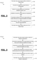
- FIGURE 2 is a schematic representation of a non-limiting exemplary embodiment of a step of adding a slave node that can be implemented in a method according to the invention.
- Stage 200 of the FIGURE 2 may be step 130 of the FIGURE 1 .
- Step 200 is performed to deploy and add a slave application node to a group of application nodes ensuring the deployment of a SaaS application.
- Step 200 is carried out for example when the measured or estimated load index exceeds a high threshold.
- Step 200 is triggered by a master application node.
- Step 200 includes an optional step 202 during which the master node communicates with the other master nodes to notify them of the start of step 200 of adding a new slave node.
- the other master nodes refrain from creating or deleting a slave node until step 200 of node creation, in progress, is completed.
- Step 200 includes a step 204 during which the master node communicates with an orchestrator, using the orchestrator APIs communicated to it at the time of its creation, to request the creation of a slave application node.
- the orchestrator creates the slave application node, for example with the same technical parameters as the master node, or with parameters previously defined for the creation of a slave node. These parameters can be stored in a configuration file stored at the master node level or at the orchestrator level. In all cases, the created slave node has a capacity greater than or equal to the master node that requested its creation, in terms of CPU/memory/network.
- the slave node When created, the slave node is assigned an internal IP address, and optionally a name. It also receives the APIs to communicate with the master node that requested its creation.
- a step 208 an instance of the SaaS application is installed and started on the slave node. This step can for example be performed by the slave node.
- the IP address, as well as the name, of the slave node is communicated, by the slave node, to the master node, which, itself, transmits said IP address and name to the load balancing module.
- the master node stores the slave node's IP address and name locally.
- the load distribution module registers the IP address and the identifier of the slave node on the list of application nodes deploying the SaaS application.
- the slave node can from this moment receive the connections to the SaaS application.
- the master node notifies the other nodes that the step of adding a slave node is complete, and optionally communicates to them the IP address and/or the name of the slave node that has just been created.
- the master node(s) update the number of slave nodes.
- FIGURE 3 is a schematic representation of a non-limiting exemplary embodiment of a step of deleting a slave node that can be implemented in a method according to the invention.
- Stage 300 of the FIGURE 3 may be step 152 of the FIGURE 1 .
- Step 300 is performed to remove a slave application node from a group of application nodes ensuring the deployment of a SaaS application, in particular during a load reduction phase.
- Step 300 is carried out for example when the measured or estimated load index falls below a low threshold.
- Step 300 is triggered by a master application node.
- Step 300 includes an optional step 302 during which the master node communicates with the other master nodes to notify them of the start of step 300 of deleting a slave node. Thus, the others refrain from creating or deleting a slave node until step 300 of deleting a node is complete.
- Step 300 includes a step 304 during which the master node communicates with the load distribution module, using the APIs of the load distribution module communicated to it at the time of its creation, to request the deletion of a slave application node from the list of application nodes that said distribution module holds.
- the load distribution module removes the name and/or IP address of the slave node from the list of application modules that it holds. Thus, the slave module in question no longer receives a new connection to the SaaS application.
- the slave module continues to provide the connections that had been assigned to it before step 306, until all the connections for which it was responsible are extinguished.
- This slave application node does not receive new connections, so that after a while this slave node no longer provides any connections to the SaaS application.
- the slave node informs the master node, deletes the instance of the SaaS application, then shuts down, during a step 310.
- the resources associated with this slave node can be destroyed or paused.
- the master node notifies the other nodes that the step of deleting a slave node is complete.
- the master node(s) update the number of slave nodes.
- FIGURE 4 is a schematic representation of a non-limiting exemplary embodiment of a system according to the invention.
- the 400 system of the FIGURE 4 can be used to implement a method according to the invention and in particular method 100 of the FIGURE 1 .
- the system 400 comprises an orchestrator 402, a load distribution module 404 and one or more master application nodes 406.
- the system 400 comprises two master nodes 406 1 and 406 2 .
- the system 400 may further comprise one or more slave application nodes 408, added by the master node(s) 406, during operation of the system, i.e. during deployment of the SaaS application.
- the system 400 comprises three slave nodes 408 1 -408 3 .
- the load balancing module 404 and each master node 406 can be created by the orchestrator 402.
- the load balancing module 404 maintains a list 410 of application nodes handling connections to the SaaS application.
- This list shows the two masters 406 1 , 406 2 and the three slave nodes 408 1 , 408 2 and 408 3 .
- Each slave node 408 runs one instance of the SaaS application, respectively 412 3 -412 4 .
- the master nodes are identical, but can be different.
- slave nodes are identical, but can be different.
- each of the nodes is a virtual machine.
- the number of master nodes is not limited to two and is greater than or equal to 1.
- the number of slave nodes is not limited to three and is greater than or equal to 0.
Landscapes
- Engineering & Computer Science (AREA)
- Signal Processing (AREA)
- Computer Networks & Wireless Communication (AREA)
- Theoretical Computer Science (AREA)
- Software Systems (AREA)
- General Engineering & Computer Science (AREA)
- General Physics & Mathematics (AREA)
- Physics & Mathematics (AREA)
- Computing Systems (AREA)
- Computer Security & Cryptography (AREA)
- Computer Hardware Design (AREA)
- Data Exchanges In Wide-Area Networks (AREA)
- Multi Processors (AREA)
Priority Applications (2)
| Application Number | Priority Date | Filing Date | Title |
|---|---|---|---|
| EP23305365.1A EP4432086A1 (de) | 2023-03-16 | 2023-03-16 | Verfahren und system zum verteilen einer saas-anwendung |
| US18/604,941 US12506799B2 (en) | 2023-03-16 | 2024-03-14 | Method and system for deploying a SAAS application |
Applications Claiming Priority (1)
| Application Number | Priority Date | Filing Date | Title |
|---|---|---|---|
| EP23305365.1A EP4432086A1 (de) | 2023-03-16 | 2023-03-16 | Verfahren und system zum verteilen einer saas-anwendung |
Publications (1)
| Publication Number | Publication Date |
|---|---|
| EP4432086A1 true EP4432086A1 (de) | 2024-09-18 |
Family
ID=86732017
Family Applications (1)
| Application Number | Title | Priority Date | Filing Date |
|---|---|---|---|
| EP23305365.1A Pending EP4432086A1 (de) | 2023-03-16 | 2023-03-16 | Verfahren und system zum verteilen einer saas-anwendung |
Country Status (2)
| Country | Link |
|---|---|
| US (1) | US12506799B2 (de) |
| EP (1) | EP4432086A1 (de) |
Citations (4)
| Publication number | Priority date | Publication date | Assignee | Title |
|---|---|---|---|---|
| US20110078303A1 (en) * | 2009-09-30 | 2011-03-31 | Alcatel-Lucent Usa Inc. | Dynamic load balancing and scaling of allocated cloud resources in an enterprise network |
| US9300728B1 (en) * | 2013-10-14 | 2016-03-29 | Ca, Inc. | Controlling resource deployment thresholds in a distributed computer system |
| US20170199770A1 (en) * | 2014-06-23 | 2017-07-13 | Getclouder Ltd. | Cloud hosting systems featuring scaling and load balancing with containers |
| US20220329651A1 (en) * | 2021-04-12 | 2022-10-13 | Electronics And Telecommunications Research Institute | Apparatus for container orchestration in geographically distributed multi-cloud environment and method using the same |
Family Cites Families (4)
| Publication number | Priority date | Publication date | Assignee | Title |
|---|---|---|---|---|
| US11061929B2 (en) * | 2019-02-08 | 2021-07-13 | Oracle International Corporation | Replication of resource type and schema metadata for a multi-tenant identity cloud service |
| EP4187408A1 (de) * | 2021-11-29 | 2023-05-31 | Bull SAS | Verfahren und system zur authentifizierung eines benutzers auf einem identitätsserver als service mit einem vertrauenswürdigen dritten |
| EP4210277B1 (de) * | 2022-01-05 | 2024-12-18 | Bull SAS | Verfahren zum herstellen eines kommunikationskanals zwischen einer lokalen anwendung und einer saas-anwendung und verfahren und system zur kommunikation zwischen diesen anwendungen |
| US11924036B1 (en) * | 2023-04-10 | 2024-03-05 | Cisco Technology, Inc. | Automatic SAAS optimization |
-
2023
- 2023-03-16 EP EP23305365.1A patent/EP4432086A1/de active Pending
-
2024
- 2024-03-14 US US18/604,941 patent/US12506799B2/en active Active
Patent Citations (4)
| Publication number | Priority date | Publication date | Assignee | Title |
|---|---|---|---|---|
| US20110078303A1 (en) * | 2009-09-30 | 2011-03-31 | Alcatel-Lucent Usa Inc. | Dynamic load balancing and scaling of allocated cloud resources in an enterprise network |
| US9300728B1 (en) * | 2013-10-14 | 2016-03-29 | Ca, Inc. | Controlling resource deployment thresholds in a distributed computer system |
| US20170199770A1 (en) * | 2014-06-23 | 2017-07-13 | Getclouder Ltd. | Cloud hosting systems featuring scaling and load balancing with containers |
| US20220329651A1 (en) * | 2021-04-12 | 2022-10-13 | Electronics And Telecommunications Research Institute | Apparatus for container orchestration in geographically distributed multi-cloud environment and method using the same |
Also Published As
| Publication number | Publication date |
|---|---|
| US20240314196A1 (en) | 2024-09-19 |
| US12506799B2 (en) | 2025-12-23 |
Similar Documents
| Publication | Publication Date | Title |
|---|---|---|
| EP3931694B1 (de) | Verfahren zur auswertung der vorrichtungen einer netzwerkinfrastruktur für den einsatz einer virtualisierten funktion | |
| FR2953352A1 (fr) | Procede de controle d'un etat de charge d'un lien physique entre deux noeuds de reseau physiques portant une pluralite de liens virtuels | |
| EP4432086A1 (de) | Verfahren und system zum verteilen einer saas-anwendung | |
| EP3051416A1 (de) | Steuerverfahren zum betreiben eines programms, das in einem maschinenpark ausgeführt werden soll | |
| WO2018122533A1 (fr) | Reseau informatique de noeuds communiquant entre eux par messages en pair a pair et procede d'interconnexion entre noeuds associe | |
| EP3205067B1 (de) | Ausstrahlung von inhalten durch streaming in einem peer-to-peer-netzwerk | |
| FR2854753A1 (fr) | Procede de distribution de documents numeriques multi-resolutions | |
| WO2025132515A1 (fr) | Procédé d'optimisation du dimensionnement d'une infrastructure de virtualisation à une charge de service | |
| EP1897360B1 (de) | Einrichtung und verfahren zum verwalten von mit der verwendung von diensten durch ein endgerät assoziierten kommunikationsguthaben | |
| WO2025003099A1 (fr) | Procédé d'adaptation du dimensionnement d'une infrastructure de virtualisation à une charge de service | |
| WO2016107840A1 (fr) | Procédé de gestion automatique de la consommation électrique d'une grappe de serveurs | |
| EP2446608B1 (de) | Verfahren für die zugriffskontrolle durch eine client-einheit auf einen server | |
| EP2860630A1 (de) | Datenübertragungsverfahren in einer dynamischen Umgebung | |
| WO2025114164A1 (fr) | Procédé de déploiement d'un service dans un environnement distribué | |
| WO2026041625A1 (fr) | Procédé d'affectation d'unités informatiques dans une architecture d'informatique en nuage | |
| WO2023217639A1 (fr) | Procédé, dispositif et système d'élaboration dynamique d'une infrastructure de données | |
| FR3135543A1 (fr) | Procédé, dispositif et système de certification d’une ressource | |
| WO2017109435A1 (fr) | Procede de configuration d'un systeme d'exploitation | |
| FR3103986A1 (fr) | Procédé de répartition de ressources dans une infrastructure en réseau | |
| FR3122010A1 (fr) | Gestion de la mémoire dans un dispositif de traitement de transactions | |
| EP4584683A1 (de) | Verfahren zur orchestrierung von softwareanwendungen in einem telekommunikationssystem, zugehöriges computerprogramm und orchestrierungsvorrichtung | |
| FR3118512A1 (fr) | Procédé de contrôle d’un ensemble de cartes de calcul d’un serveur multimédia embarqué à bord d’un aéronef, programme d’ordinateur, dispositif électronique de contrôle, et serveur multimédia associés | |
| Ait Elmrabti et al. | Les défis de sécurité dans le Cloud Computing: Problèmes et solutions de la sécurité en Cloud Computing | |
| WO2019170974A1 (fr) | Procédé et système pour la construction d'un plan d'acquisitions pour satellite | |
| FR3031204A1 (fr) | Procede et systeme d'allocation de ressources de traitement pour l'execution d'un programme d'un equipement client |
Legal Events
| Date | Code | Title | Description |
|---|---|---|---|
| PUAI | Public reference made under article 153(3) epc to a published international application that has entered the european phase |
Free format text: ORIGINAL CODE: 0009012 |
|
| STAA | Information on the status of an ep patent application or granted ep patent |
Free format text: STATUS: THE APPLICATION HAS BEEN PUBLISHED |
|
| AK | Designated contracting states |
Kind code of ref document: A1 Designated state(s): AL AT BE BG CH CY CZ DE DK EE ES FI FR GB GR HR HU IE IS IT LI LT LU LV MC ME MK MT NL NO PL PT RO RS SE SI SK SM TR |
|
| STAA | Information on the status of an ep patent application or granted ep patent |
Free format text: STATUS: REQUEST FOR EXAMINATION WAS MADE |
|
| 17P | Request for examination filed |
Effective date: 20250212 |
|
| STAA | Information on the status of an ep patent application or granted ep patent |
Free format text: STATUS: EXAMINATION IS IN PROGRESS |
|
| 17Q | First examination report despatched |
Effective date: 20250423 |
|
| P01 | Opt-out of the competence of the unified patent court (upc) registered |
Free format text: CASE NUMBER: APP_22852/2025 Effective date: 20250514 |