EP4431827A1 - Cooling system and pretreatment module therefor - Google Patents
Cooling system and pretreatment module therefor Download PDFInfo
- Publication number
- EP4431827A1 EP4431827A1 EP24163184.5A EP24163184A EP4431827A1 EP 4431827 A1 EP4431827 A1 EP 4431827A1 EP 24163184 A EP24163184 A EP 24163184A EP 4431827 A1 EP4431827 A1 EP 4431827A1
- Authority
- EP
- European Patent Office
- Prior art keywords
- liquid
- branch
- cooling device
- heat exchanger
- mode
- Prior art date
- Legal status (The legal status is an assumption and is not a legal conclusion. Google has not performed a legal analysis and makes no representation as to the accuracy of the status listed.)
- Granted
Links
Images
Classifications
-
- F—MECHANICAL ENGINEERING; LIGHTING; HEATING; WEAPONS; BLASTING
- F24—HEATING; RANGES; VENTILATING
- F24F—AIR-CONDITIONING; AIR-HUMIDIFICATION; VENTILATION; USE OF AIR CURRENTS FOR SCREENING
- F24F11/00—Control or safety arrangements
- F24F11/62—Control or safety arrangements characterised by the type of control or by internal processing, e.g. using fuzzy logic, adaptive control or estimation of values
- F24F11/63—Electronic processing
- F24F11/65—Electronic processing for selecting an operating mode
-
- H—ELECTRICITY
- H05—ELECTRIC TECHNIQUES NOT OTHERWISE PROVIDED FOR
- H05K—PRINTED CIRCUITS; CASINGS OR CONSTRUCTIONAL DETAILS OF ELECTRIC APPARATUS; MANUFACTURE OF ASSEMBLAGES OF ELECTRICAL COMPONENTS
- H05K7/00—Constructional details common to different types of electric apparatus
- H05K7/20—Modifications to facilitate cooling, ventilating, or heating
- H05K7/20709—Modifications to facilitate cooling, ventilating, or heating for server racks or cabinets; for data centers, e.g. 19-inch computer racks
- H05K7/20836—Thermal management, e.g. server temperature control
-
- F—MECHANICAL ENGINEERING; LIGHTING; HEATING; WEAPONS; BLASTING
- F24—HEATING; RANGES; VENTILATING
- F24F—AIR-CONDITIONING; AIR-HUMIDIFICATION; VENTILATION; USE OF AIR CURRENTS FOR SCREENING
- F24F11/00—Control or safety arrangements
- F24F11/70—Control systems characterised by their outputs; Constructional details thereof
- F24F11/80—Control systems characterised by their outputs; Constructional details thereof for controlling the temperature of the supplied air
- F24F11/83—Control systems characterised by their outputs; Constructional details thereof for controlling the temperature of the supplied air by controlling the supply of heat-exchange fluids to heat-exchangers
-
- F—MECHANICAL ENGINEERING; LIGHTING; HEATING; WEAPONS; BLASTING
- F24—HEATING; RANGES; VENTILATING
- F24F—AIR-CONDITIONING; AIR-HUMIDIFICATION; VENTILATION; USE OF AIR CURRENTS FOR SCREENING
- F24F11/00—Control or safety arrangements
- F24F11/70—Control systems characterised by their outputs; Constructional details thereof
- F24F11/80—Control systems characterised by their outputs; Constructional details thereof for controlling the temperature of the supplied air
- F24F11/83—Control systems characterised by their outputs; Constructional details thereof for controlling the temperature of the supplied air by controlling the supply of heat-exchange fluids to heat-exchangers
- F24F11/84—Control systems characterised by their outputs; Constructional details thereof for controlling the temperature of the supplied air by controlling the supply of heat-exchange fluids to heat-exchangers using valves
-
- F—MECHANICAL ENGINEERING; LIGHTING; HEATING; WEAPONS; BLASTING
- F24—HEATING; RANGES; VENTILATING
- F24F—AIR-CONDITIONING; AIR-HUMIDIFICATION; VENTILATION; USE OF AIR CURRENTS FOR SCREENING
- F24F3/00—Air-conditioning systems in which conditioned primary air is supplied from one or more central stations to distributing units in the rooms or spaces where it may receive secondary treatment; Apparatus specially designed for such systems
- F24F3/12—Air-conditioning systems in which conditioned primary air is supplied from one or more central stations to distributing units in the rooms or spaces where it may receive secondary treatment; Apparatus specially designed for such systems characterised by the treatment of the air otherwise than by heating and cooling
- F24F3/14—Air-conditioning systems in which conditioned primary air is supplied from one or more central stations to distributing units in the rooms or spaces where it may receive secondary treatment; Apparatus specially designed for such systems characterised by the treatment of the air otherwise than by heating and cooling by humidification; by dehumidification
-
- F—MECHANICAL ENGINEERING; LIGHTING; HEATING; WEAPONS; BLASTING
- F24—HEATING; RANGES; VENTILATING
- F24F—AIR-CONDITIONING; AIR-HUMIDIFICATION; VENTILATION; USE OF AIR CURRENTS FOR SCREENING
- F24F5/00—Air-conditioning systems or apparatus not covered by F24F1/00 or F24F3/00, e.g. using solar heat or combined with household units such as an oven or water heater
- F24F5/0007—Air-conditioning systems or apparatus not covered by F24F1/00 or F24F3/00, e.g. using solar heat or combined with household units such as an oven or water heater cooling apparatus specially adapted for use in air-conditioning
- F24F5/0035—Air-conditioning systems or apparatus not covered by F24F1/00 or F24F3/00, e.g. using solar heat or combined with household units such as an oven or water heater cooling apparatus specially adapted for use in air-conditioning using evaporation
-
- H—ELECTRICITY
- H05—ELECTRIC TECHNIQUES NOT OTHERWISE PROVIDED FOR
- H05K—PRINTED CIRCUITS; CASINGS OR CONSTRUCTIONAL DETAILS OF ELECTRIC APPARATUS; MANUFACTURE OF ASSEMBLAGES OF ELECTRICAL COMPONENTS
- H05K7/00—Constructional details common to different types of electric apparatus
- H05K7/20—Modifications to facilitate cooling, ventilating, or heating
- H05K7/20709—Modifications to facilitate cooling, ventilating, or heating for server racks or cabinets; for data centers, e.g. 19-inch computer racks
- H05K7/20718—Forced ventilation of a gaseous coolant
-
- F—MECHANICAL ENGINEERING; LIGHTING; HEATING; WEAPONS; BLASTING
- F24—HEATING; RANGES; VENTILATING
- F24F—AIR-CONDITIONING; AIR-HUMIDIFICATION; VENTILATION; USE OF AIR CURRENTS FOR SCREENING
- F24F3/00—Air-conditioning systems in which conditioned primary air is supplied from one or more central stations to distributing units in the rooms or spaces where it may receive secondary treatment; Apparatus specially designed for such systems
- F24F3/12—Air-conditioning systems in which conditioned primary air is supplied from one or more central stations to distributing units in the rooms or spaces where it may receive secondary treatment; Apparatus specially designed for such systems characterised by the treatment of the air otherwise than by heating and cooling
- F24F3/14—Air-conditioning systems in which conditioned primary air is supplied from one or more central stations to distributing units in the rooms or spaces where it may receive secondary treatment; Apparatus specially designed for such systems characterised by the treatment of the air otherwise than by heating and cooling by humidification; by dehumidification
- F24F2003/144—Air-conditioning systems in which conditioned primary air is supplied from one or more central stations to distributing units in the rooms or spaces where it may receive secondary treatment; Apparatus specially designed for such systems characterised by the treatment of the air otherwise than by heating and cooling by humidification; by dehumidification by dehumidification only
Definitions
- the present invention relates to the field of refrigeration devices, in particular to a pretreatment module (such as for data center heat dissapation) and a cooling system configured with the pretreatment module.
- a pretreatment module such as for data center heat dissapation
- a cooling system configured with the pretreatment module.
- refrigeration systems are typically equipped with both a mechanical refrigeration device and a natural cooling device.
- Mechanical refrigeration devices are refrigeration devices based on traditional compressors, while natural cooling devices aim to use ambient air for cooling.
- ambient temperature is relatively low, only natural cooling devices can be adopted to meet the load demand by utilizing the cold air from the outdoor environment. As the ambient temperature increases, natural cooling alone may not be able to meet the cooling demand.
- mechanical refrigeration devices and natural cooling devices can be used in combination.
- the mechanical refrigeration devices are configured with compressors, the energy consumption of the mechanical refrigeration devices during operation is significantly higher than that of the natural cooling devices.
- the object of at least preferred embodiments of the present invention is to solve or at least alleviate the problems existing in the prior art.
- the object of the present invention is to solve the problem of high energy consumption ratio of air conditioning in existing cooling systems.
- a pretreatment module for a cooling system comprising:
- the pretreatment module further comprises an additional pipeline and valve assembly, wherein liquid flow paths of the first dehumidification heat exchanger and the second dehumidification heat exchanger are connected to a first liquid port and a second liquid port of the cooling system through the additional pipeline and valve assembly.
- the additional pipeline and valve assembly is configured such that in the first mode, the liquid flow path of the first dehumidification heat exchanger communicates with the first liquid port and the second liquid port of the cooling system, and the communication from the liquid flow path of the second dehumidification heat exchanger to the first liquid port or the second liquid port of the cooling system is cut off; and in the second mode, the liquid flow path of the second dehumidification heat exchanger communicates with the first liquid port and the second liquid port of the cooling system, and the communication from the liquid flow path of the first dehumidification heat exchanger to the first liquid port or the second liquid port of the cooling system is cut off.
- the pipeline and valve assembly comprises:
- the additional pipeline and valve assembly comprises:
- a first driving device such as a first pump, is provided on a pipeline near the air inlet, where the first driving device draws ambient air into the natural cooling device.
- a second driving device such as a second pump, is provided on a pipeline near the air outlet, where the second driving device discharges air from the natural cooling device to the environment.
- either the first main flow path or the second main flow path includes a third driving device, such as a third pump, where the third driving device drives the liquid cooling medium to circulate.
- a third driving device such as a third pump
- a cooling system comprising: a pretreatment module (e.g. as described above) and a natural cooling device connected to the pretreatment module, wherein the natural cooling device comprises a direct evaporative cooling device and/or an indirect evaporative cooling device.
- the natural cooling device is configured to cool air entering from the air inlet through direct evaporative cooling and indirect evaporative cooling with the liquid cooling medium from the second liquid port and transport the air to a load.
- the natural cooling device is configured to cool liquid cooling medium from the second liquid port through direct evaporative cooling with the air entering from the air inlet and transport the liquid cooling medium to the load.
- the natural cooling device comprises: a direct evaporative cooling device and an indirect evaporative cooling device, wherein, the liquid cooling medium from the second liquid port sequentially passes through the direct evaporative cooling device and the indirect evaporative cooling device, and is circulated from the first liquid port to the liquid flow path of one of the first dehumidification heat exchanger and the second dehumidification heat exchanger, and absorbing the adsorption heat generated during the dehumidification, where a first part of the airflow from the air inlet is cooled by passing through a dry channel of the indirect evaporative cooling device and is transported to the load, a second part of the airflow from the air inlet or ambient air is discharged after heat and mass exchange with the liquid cooling medium in the direct evaporative cooling device, and a third part of the airflow from the air inlet or ambient air is discharged after heat and mass exchange with the liquid cooling medium in a wet channel of the indirect evaporative cooling device.
- the natural cooling device comprises: a first direct evaporative cooling device and a second direct evaporative cooling device, wherein, the liquid cooling medium from the second liquid port is transported to the load after sequentially passing through the first direct evaporative cooling device and the second direct evaporative cooling device, and then is circulated from the first liquid port to the liquid flow path of one of the first dehumidification heat exchanger and the second dehumidification heat exchanger to absorb the adsorption heat generated during the dehumidification, where the ambient air or a part of the airflow from the air inlet is discharged after heat and mass exchange with the liquid cooling medium in the first direct evaporative cooling device, and the airflow from the air inlet is discharged after heat and mass exchange with the liquid cooling medium in the second direct evaporative cooling device.
- the cooling system further comprises: a mechanical refrigeration device comprising a compressor, a condenser, a throttling device, and an evaporator connected in sequence.
- a mechanical refrigeration device comprising a compressor, a condenser, a throttling device, and an evaporator connected in sequence.
- the cooling system is capable of operating in a natural cooling mode, an auxiliary natural cooling mode, a collaborative refrigeration mode, or a mechanical refrigeration mode, where only the natural cooling device is in operation in the natural cooling mode, the pretreatment module and the natural cooling device operate together in the auxiliary natural cooling mode, the pretreatment module, the natural cooling device, and the mechanical refrigeration device operate together in the collaborative refrigeration mode, and only the mechanical refrigeration device is in operation in the mechanical refrigeration mode.
- the cooling system determines the operating mode based on ambient temperature and humidity.
- the air heated by the load is mixed with optional ambient air, and is then transported to the first dehumidification heat exchanger or the second dehumidification heat exchanger after passing through a condenser in the mechanical refrigeration device.
- the pretreatment module when in operation, periodically switches between the first mode and the second mode.
- the pretreatment module and cooling system according to embodiments of the present invention can improve the overall efficiency of the cooling system and reduce its overall energy consumption.
- the cooling system comprises a pretreatment module 1 and a natural cooling device 2 connected to the pretreatment module 1, wherein the natural cooling device 2 is a device based on direct evaporative cooling and/or indirect evaporative cooling for cooling a load 4.
- the load 4 is a data center machine room that includes a plurality of servers 9.
- the load 4 can be any other device that requires heat dissipation on a long-term basis.
- the natural cooling device 2 can be directly adopted to meet the heat dissipation needs of the load 4.
- ambient air can first be cooled through direct or indirect evaporative cooling in the natural cooling device 2, and then provided to a mixing box 41 in the machine room 4 for circulation in the machine room 4, while the hot air in the machine room 4 is discharged through an outlet channel 42.
- the natural cooling device 2 alone may not be able to meet the heat dissipation needs of the machine room 4.
- the pretreatment module 1 can be activated to dehumidify the ambient air and supply the dehumidified ambient air to the natural cooling device 2, so as to reduce the temperature of the cooling medium provided to the load 4 through the natural cooling device 2, improve the cooling capacity of the natural cooling device 2, and broaden the applicable ambient temperature and humidity range of the natural cooling device 2, thereby reducing the overall energy consumption of the cooling system.
- the pretreatment module 1 comprises: a first airflow path 11, a second airflow path 13, and a pipeline and valve assembly.
- the first airflow path 11 is provided with a first dehumidification heat exchanger 12, and the second airflow path 13 is provided with a second dehumidification heat exchanger 14.
- the first end of the first airflow path 11 and the first end of the second airflow path 13 communicate with the ambient air.
- the second end of the first airflow path 11 and the second end of the second airflow path 13 are connected to an air inlet 201 and an air outlet 202 of the natural cooling device of the cooling system through the pipeline and valve assembly.
- the pipeline and valve assembly is configured to switch between a first mode as shown in FIG. 1 and a second mode as shown in FIG. 2 .
- the pipeline and valve assembly In the first mode, the pipeline and valve assembly is configured such that the first airflow path 11 communicates with the air inlet 201 of the cooling system, and the second airflow path 13 communicates with the air outlet 202 of the cooling system. And, in the second mode, the pipeline and valve assembly is configured such that the first airflow path 11 communicates with the air outlet 202 of the cooling system, and the second airflow path 13 communicates with the air inlet 201 of the cooling system.
- one of the first dehumidification heat exchanger 12 and the second dehumidification heat exchanger 14 can be used to reduce the humidity of the introduced ambient air, while the other can be regenerated through the hot air from the load, that is, to remove the moisture adsorbed by the dehumidification heat exchanger and restore its ability to absorb moisture again.
- the first dehumidification heat exchanger 12 plays a dehumidification role, while the second dehumidification heat exchanger 14 is regenerated using the hot air from the load to remove the moisture adsorbed therein.
- the second dehumidification heat exchanger 14 plays a dehumidification role, while the first dehumidification heat exchanger 12 is regenerated using the hot air from the load to remove the moisture adsorbed therein. Therefore, by switching the pretreatment module 1 between the first mode and the second mode, it can be ensured that the pretreatment module 1 continuously supplies dehumidified ambient air to the natural cooling device 2.
- the pipeline and valve assembly comprises: a first branch 15 and a second branch 16 respectively connected from the first airflow path 11 to the air inlet 201 and the air outlet 202, where a first valve 151 and a second valve 161 are respectively provided on the first branch 15 and the second branch 16; and a third branch 18 and a fourth branch 17 respectively connected from the second airflow path 13 to the air inlet 201 and the air outlet 202, where a third valve 181 and a fourth valve 171 are respectively provided on the third branch 18 and the fourth branch 17.
- the switching between the first mode and the second mode can be achieved by controlling the open and close of the first valve, second valve, third valve and fourth valve. For example, in the first mode shown in FIG.
- the first valve 151 and the fourth valve 171 are opened, and the second valve 161 and the third valve 181 are closed.
- the first valve 151 and the fourth valve 171 are opened, and the second valve 161 and the third valve 181 are closed.
- the four valves can be replaced by the following arrangement, that is, a first three-way valve is provided at the intersection of the first airflow path 11, the first branch 15 and the second branch 16, and a second three-way valve is provided at the intersection of the second airflow path 13, the third branch 17 and the fourth branch 18.
- Switching between the first mode and the second mode can also be achieved by controlling the first three-way valve and the second three-way valve.
- the pipeline and valve assembly can have any other suitable arrangement different from that shown in the figures. For example, switching between the first mode and the second mode can be achieved by only configuring a single four-way valve.
- the pretreatment module further comprises an additional pipeline and valve assembly.
- the liquid flow paths of the first dehumidification heat exchanger 12 and the second dehumidification heat exchanger 14 are connected to the first liquid port 203 and the second liquid end 204 of the natural cooling device of the cooling system through the additional pipeline and valve assembly.
- the additional pipeline and valve assembly is configured such that in the first mode, the liquid flow path of the first dehumidification heat exchanger 12 communicates with the first liquid port 203 and the second liquid port 204 of the cooling system, and the communication from the liquid flow path of the second dehumidification heat exchanger 14 to the first liquid port 203 and/or the second liquid port 204 of the cooling system is cut off.
- the liquid flow path of the second dehumidification heat exchanger 14 communicates with the first liquid port 203 and the second liquid port 204 of the cooling system, and the communication from the liquid flow path of the first dehumidification heat exchanger 12 to the first liquid port 203 and/or the second liquid port 204 of the cooling system is cut off.
- the additional pipeline and valve assembly comprises: a first main flow path 22 connected to the first liquid port 203 of the cooling system, a first liquid branch 221 and a second liquid branch 222 respectively connected from the first main flow path 22 to the liquid flow path inlet 121 of the first dehumidification heat exchanger 12 and the liquid flow path inlet 141 of the second dehumidification heat exchanger 14, a second main flow path 23 connected to the second liquid port 204 of the cooling system, and a third liquid branch 231 and a fourth liquid branch 232 respectively connected from the second main flow path 23 to the liquid flow path outlet 122 of the first dehumidification heat exchanger 12 and the liquid flow path outlet 142 of the second dehumidification heat exchanger 14.
- the first liquid branch 221 and the second liquid branch 222 are respectively provided with a first shut-off valve 51 and a second shut-off valve 52.
- the first shut-off valve 51 can be provided on the third liquid branch 231.
- the second shut-off valve 52 can be provided on the fourth liquid branch 232.
- the first shut-off valve 51 is opened while the second shut-off valve 52 is closed.
- the first shut-off valve 51 is closed while the second shut-off valve 52 is opened.
- a third three-way valve is provided at the intersection of the first main flow path 22, the first liquid branch 221, and the second liquid branch 222, and a fourth three-way valve is provided at the intersection of the second main flow path 23, the third liquid branch 231, and the fourth liquid branch 232.
- a single four-way valve can also be used to replace two three-way valves.
- a first driving device such as a first pump 191
- a second driving device such as a second pump 192
- the third driving device drives the liquid cooling medium to circulate.
- a cooling system comprising: the pretreatment module 1 according to the various embodiments, and a natural cooling device 2 connected to the pretreatment module 1, wherein the natural cooling device 2 comprises a direct evaporative cooling device and/or an indirect evaporative cooling device.
- the natural cooling device 2 is configured to cool the air entering from the air inlet 201 through direct evaporative cooling and indirect evaporative cooling with the liquid cooling medium from the second liquid port 204 and transport the air to the load 4, as is described in detail below in conjunction with FIG. 3 , or to cool the liquid cooling medium from the second liquid port 204 through direct evaporative cooling with the air entering from the air inlet 201 and transport the liquid cooling medium to the load 4, as is described in detail below in conjunction with FIG. 4 .
- the natural cooling device comprises: a direct evaporative cooling device 211 and an indirect evaporative cooling device 212.
- the liquid cooling medium from the second liquid port 204 of the cooling system sequentially passes through the direct evaporative cooling device 211 and the indirect evaporative cooling device 212, and is circulated from the first liquid port 203 to the liquid flow path of one of the first dehumidification heat exchanger 12 and the second dehumidification heat exchanger 14 that is in a dehumidification operation, absorbing the adsorption heat generated during the dehumidification.
- a first part A1 of the airflow from the air inlet 201 is cooled by passing through the dry channel of the indirect evaporative cooling device 212 and is transported to the load 4.
- a second part A2 of the airflow from the air inlet is discharged after heat and mass exchange with the liquid cooling medium in the direct evaporative cooling device 211, i.e., discharged to the environment or other suitable places, thereby obtaining cooling medium at a lower temperature.
- a third part A3 of the airflow from the air inlet is discharged after heat and mass exchange with the low-temperature cooling medium from the direct evaporative cooling device 211 in the wet channel of the indirect evaporative cooling device 212.
- ambient air can be used to heat and mass exchange with liquid cooling medium in the direct evaporative cooling device 211 and the indirect evaporative cooling device 212 and then be discharged, or ambient air can be used in the direct evaporative cooling device 211 and a part of the airflow from the air inlet 201 can be used in the indirect evaporative cooling device 212.
- low-temperature cooling medium can be obtained through the direct evaporative cooling device 211, where the low-temperature cooling medium is used to reduce the temperature of the first part A1 of the airflow in the indirect evaporative cooling device 212.
- the natural cooling device 2 comprises: a first direct evaporative cooling device 213 and a second direct evaporative cooling device 214.
- the liquid cooling medium from the second liquid port 204 is transported to the load 4 after sequentially passing through the first direct evaporative cooling device 213 and the second direct evaporative cooling device 214, and then is circulated from the first liquid port 203 to the liquid flow path of one of the first dehumidification heat exchanger 12 and the second dehumidification heat exchanger 14 that is in a dehumidification operation, absorbing the adsorption heat generated.
- the ambient air B1 or alternatively a part of the airflow A4 from the air inlet can be introduced to the first direct evaporative cooling device 213 for heat and mass exchange with the liquid cooling medium and then be discharged. And, the airflow A4 (partially or entirely) from the air inlet is discharged after heat and mass exchange with the liquid cooling medium in the second direct evaporative cooling device 214.
- a fourth pump 194 is provided between the first direct evaporative cooling device 213 and the second direct evaporative cooling device 214.
- a machine room air treater 43 is arranged at the load 4, and the hot air flow for regeneration of the dehumidification heat exchanger is generated by using the ambient air B2 to exchange heat with the load 4 at the heat exchanger 44.
- the natural cooling device 2 in FIGS. 3 or 4 is only illustrative, and in alternative embodiments, the natural cooling device 2 may have other suitable structures.
- FIG. 4 also illustrates a mechanical refrigeration device 5 in the cooling system, which is activated when the heat dissipation demand of the load 4 cannot be met when both the natural cooling device 2 and the pretreatment module 1 operate together.
- the mechanical refrigeration device 5 is a conventional compressor-based refrigeration loop, which includes a compressor 51, a condenser 52, a throttling device 53, and an evaporator 54 connected in sequence, wherein the evaporator 54 is used to cool the load 4. Therefore, the cooling system according to the embodiments of the present invention can operate in any of the natural cooling mode, auxiliary natural cooling mode, collaborative refrigeration mode, or mechanical refrigeration mode. In the natural cooling mode, only the natural cooling device 2 is in operation.
- the pretreatment module 1 and natural cooling device 2 operate together.
- the pretreatment module 1, natural cooling device 2, and mechanical refrigeration device 5 operate together.
- the mechanical refrigeration mode the mechanical refrigeration device 5 operates alone.
- the operating mode of the cooling system is determined based on ambient temperature and humidity.
- the enthalpy-humidity chart of humid air may include four regions corresponding to the four operating modes, where the mode to be executed is determined based on which region the actual ambient temperature and humidity locate in.
- the air heated by the load 4 can be mixed with the ambient air 101 before being transported to the first or second dehumidification heat exchanger to increase the flow amount of the airflow used for regeneration.
- the ambient airflow B2 heated by the load 4 can be adopted and transported to the first dehumidification heat exchanger or the second dehumidification heat exchanger after passing through the condenser 52 in the mechanical refrigeration device 5.
- the temperature of the airflow used for regeneration can be further increased when the condenser 52 is operating, thereby improving the speed and adequacy of regeneration, so as to remove the moisture absorbed by the dehumidification heat exchanger more quickly and thoroughly.
- the pretreatment module 1 can periodically switch between the first mode and the second mode when it is activated, where the switching frequency can be determined based on the ambient temperature and humidity, the temperature and humidity of regeneration air, the regeneration rate, the dehumidification effect and the like.
- direct evaporative cooling refers to the direct contact between air and cooling medium, such as water, in the pipeline, which can increase the humidity of the air and decrease its temperature, thus reaching the temperature T wb as shown by the arrow in the figure.
- air and cooling medium such as water
- air and cooling medium come into direct contact in the pipeline in a wet channel, which can increase the humidity and decrease the temperature of the air, while the airflow in another dry channel exchanges heat with the fluid in the wet channel, thereby reducing the temperature while keeping the humidity constant.
- the minimum temperature T dp that can be achieved through indirect evaporative cooling depends on the humidity of the airflow in the dry channel. Referring to FIG. 7 , after dehumidification, the ambient air can be further reduced to a minimum temperature of T dp2 from T dp1 through indirect evaporative cooling. Similarly, the minimum temperature that can be achieved through direct evaporative cooling also decreases as a result of decreasing humidity.
- the device according to the embodiments of the present invention when as the ambient temperature rises, it is possible to use the natural cooling device as long as possible and activate the mechanical refrigeration device with higher energy comsumption as late as possible, thereby reducing the overall energy consumption of the cooling system and improving its overall efficiency.
Landscapes
- Engineering & Computer Science (AREA)
- General Engineering & Computer Science (AREA)
- Chemical & Material Sciences (AREA)
- Mechanical Engineering (AREA)
- Combustion & Propulsion (AREA)
- Physics & Mathematics (AREA)
- Signal Processing (AREA)
- Microelectronics & Electronic Packaging (AREA)
- Thermal Sciences (AREA)
- Computer Hardware Design (AREA)
- Life Sciences & Earth Sciences (AREA)
- Sustainable Development (AREA)
- Fuzzy Systems (AREA)
- Mathematical Physics (AREA)
- Central Air Conditioning (AREA)
Abstract
Description
- The present invention relates to the field of refrigeration devices, in particular to a pretreatment module (such as for data center heat dissapation) and a cooling system configured with the pretreatment module.
- For data center heat dissapation, refrigeration systems are typically equipped with both a mechanical refrigeration device and a natural cooling device. Mechanical refrigeration devices are refrigeration devices based on traditional compressors, while natural cooling devices aim to use ambient air for cooling. When the ambient temperature is relatively low, only natural cooling devices can be adopted to meet the load demand by utilizing the cold air from the outdoor environment. As the ambient temperature increases, natural cooling alone may not be able to meet the cooling demand. In this case, mechanical refrigeration devices and natural cooling devices can be used in combination. As the mechanical refrigeration devices are configured with compressors, the energy consumption of the mechanical refrigeration devices during operation is significantly higher than that of the natural cooling devices.
- The object of at least preferred embodiments of the present invention is to solve or at least alleviate the problems existing in the prior art.
- According to some aspects, the object of the present invention is to solve the problem of high energy consumption ratio of air conditioning in existing cooling systems.
- According to a first aspect of the invention there is provided a pretreatment module for a cooling system comprising:
- a first airflow path and a second airflow path, wherein the first airflow path is provided with a first dehumidification heat exchanger, and the second airflow path is provided with a second dehumidification heat exchanger, where a first end of the first airflow path and a first end of the second airflow path communicate to ambient air; and
- a pipeline and valve assembly, wherein a second end of the first airflow path and a second end of the second airflow path are connected to an air inlet and an air outlet of a natural cooling device of the cooling system through the pipeline and valve assembly;
- wherein, the pipeline and valve assembly is configured to switch between a first mode and a second mode;
- in the first mode, the pipeline and valve assembly is configured such that the first airflow path communicates to the air inlet, and the second airflow path communicates to the air outlet; and
- in the second mode, the pipeline and valve assembly is configured such that the first airflow path communicates to the air outlet, and the second airflow path communicates to the air inlet.
- Optionally, the pretreatment module further comprises an additional pipeline and valve assembly, wherein liquid flow paths of the first dehumidification heat exchanger and the second dehumidification heat exchanger are connected to a first liquid port and a second liquid port of the cooling system through the additional pipeline and valve assembly.
- Optionally, the additional pipeline and valve assembly is configured such that in the first mode, the liquid flow path of the first dehumidification heat exchanger communicates with the first liquid port and the second liquid port of the cooling system, and the communication from the liquid flow path of the second dehumidification heat exchanger to the first liquid port or the second liquid port of the cooling system is cut off; and
in the second mode, the liquid flow path of the second dehumidification heat exchanger communicates with the first liquid port and the second liquid port of the cooling system, and the communication from the liquid flow path of the first dehumidification heat exchanger to the first liquid port or the second liquid port of the cooling system is cut off. - Optionally, the pipeline and valve assembly comprises:
- a first branch and a second branch respectively connected from the first airflow path to the air inlet and the air outlet;
- a third branch and a fourth branch respectively connected from the second airflow path to the air inlet and the air outlet;
- wherein, the first branch is provided with a first valve, the second branch is provided with a second valve, the third branch is provided with a third valve, and the fourth branch is provided with a fourth valve; or
- a first three-way valve is provided at an intersection of the first airflow path, the first branch, and the second branch, and a second three-way valve is provided at an intersection of the second airflow path, the third branch, and the fourth branch.
- Optionally, the additional pipeline and valve assembly comprises:
- a first main flow path connected to the first liquid port of the cooling system, a first liquid branch and a second liquid branch respectively connected from the first main flow path to the liquid flow path inlet of the first dehumidification heat exchanger and the liquid flow path inlet of the second dehumidification heat exchanger, a second main flow path connected to the second liquid port of the cooling system, and a third liquid branch and a fourth liquid branch respectively connected from the second main flow path to the liquid flow path outlet of the first dehumidification heat exchanger and the liquid flow path outlet of the second dehumidification heat exchanger;
- wherein, one of the first liquid branch and the third liquid branch includes a first shut-off valve, and one of the second liquid branch and the fourth liquid branch includes a second shut-off valve; or
- a third three-way valve is provided at an intersection of the first main flow path, the first liquid branch, and the second liquid branch, and a fourth three-way valve is provided at an intersection of the second main flow path, the third liquid branch, and the fourth liquid branch.
- Optionally, a first driving device, such as a first pump, is provided on a pipeline near the air inlet, where the first driving device draws ambient air into the natural cooling device.
- Optionally, a second driving device, such as a second pump, is provided on a pipeline near the air outlet, where the second driving device discharges air from the natural cooling device to the environment.
- Optionally, either the first main flow path or the second main flow path includes a third driving device, such as a third pump, where the third driving device drives the liquid cooling medium to circulate.
- According to a second aspect of the invention there is provided a cooling system comprising: a pretreatment module (e.g. as described above) and a natural cooling device connected to the pretreatment module, wherein the natural cooling device comprises a direct evaporative cooling device and/or an indirect evaporative cooling device.
- Optionally, the natural cooling device is configured to cool air entering from the air inlet through direct evaporative cooling and indirect evaporative cooling with the liquid cooling medium from the second liquid port and transport the air to a load.
- Optionally, the natural cooling device is configured to cool liquid cooling medium from the second liquid port through direct evaporative cooling with the air entering from the air inlet and transport the liquid cooling medium to the load.
- Optionally, the natural cooling device comprises: a direct evaporative cooling device and an indirect evaporative cooling device, wherein, the liquid cooling medium from the second liquid port sequentially passes through the direct evaporative cooling device and the indirect evaporative cooling device, and is circulated from the first liquid port to the liquid flow path of one of the first dehumidification heat exchanger and the second dehumidification heat exchanger, and absorbing the adsorption heat generated during the dehumidification, where a first part of the airflow from the air inlet is cooled by passing through a dry channel of the indirect evaporative cooling device and is transported to the load, a second part of the airflow from the air inlet or ambient air is discharged after heat and mass exchange with the liquid cooling medium in the direct evaporative cooling device, and a third part of the airflow from the air inlet or ambient air is discharged after heat and mass exchange with the liquid cooling medium in a wet channel of the indirect evaporative cooling device.
- Optionally, the natural cooling device comprises: a first direct evaporative cooling device and a second direct evaporative cooling device, wherein, the liquid cooling medium from the second liquid port is transported to the load after sequentially passing through the first direct evaporative cooling device and the second direct evaporative cooling device, and then is circulated from the first liquid port to the liquid flow path of one of the first dehumidification heat exchanger and the second dehumidification heat exchanger to absorb the adsorption heat generated during the dehumidification, where the ambient air or a part of the airflow from the air inlet is discharged after heat and mass exchange with the liquid cooling medium in the first direct evaporative cooling device, and the airflow from the air inlet is discharged after heat and mass exchange with the liquid cooling medium in the second direct evaporative cooling device.
- Optionally, the cooling system further comprises: a mechanical refrigeration device comprising a compressor, a condenser, a throttling device, and an evaporator connected in sequence.
- Optionally, the cooling system is capable of operating in a natural cooling mode, an auxiliary natural cooling mode, a collaborative refrigeration mode, or a mechanical refrigeration mode, where only the natural cooling device is in operation in the natural cooling mode, the pretreatment module and the natural cooling device operate together in the auxiliary natural cooling mode, the pretreatment module, the natural cooling device, and the mechanical refrigeration device operate together in the collaborative refrigeration mode, and only the mechanical refrigeration device is in operation in the mechanical refrigeration mode.
- Optionally, the cooling system determines the operating mode based on ambient temperature and humidity.
- Optionally, the air heated by the load is mixed with optional ambient air, and is then transported to the first dehumidification heat exchanger or the second dehumidification heat exchanger after passing through a condenser in the mechanical refrigeration device.
- Optionally, when in operation, the pretreatment module periodically switches between the first mode and the second mode.
- The pretreatment module and cooling system according to embodiments of the present invention can improve the overall efficiency of the cooling system and reduce its overall energy consumption.
- With reference to the accompanying drawings, certain exemplary embodiments will now be described in greater detail by way of example only so that the present disclosure will become easier to understand. Those skilled in the art would easily understand that these drawings are for the purpose of illustration, and are not intended to limit the scope of protection which is defined by the claims. In addition, in the figures, similar numerals are used to denote similar components, where:
-
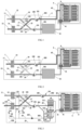
FIGS. 1 and 2 respectively show the schematic diagrams of a cooling system when the pretreatment module is in the first mode and the second mode; -
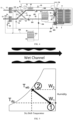
FIG. 3 shows a schematic diagram of another cooling system; -
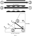
FIG. 4 shows a schematic diagram of yet another cooling system; -
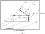
FIGS. 5 to 7 show the schematic diagrams of direct evaporative cooling and indirect evaporative cooling, as well as the temperature and humidity curves. - Referring to
FIGS. 1 and 2 , a cooling system is shown. The cooling system comprises apretreatment module 1 and anatural cooling device 2 connected to thepretreatment module 1, wherein thenatural cooling device 2 is a device based on direct evaporative cooling and/or indirect evaporative cooling for cooling a load 4. In the illustrated embodiment, the load 4 is a data center machine room that includes a plurality ofservers 9. Alternatively, the load 4 can be any other device that requires heat dissipation on a long-term basis. When the ambient temperature is sufficiently low, such as in winter, thenatural cooling device 2 can be directly adopted to meet the heat dissipation needs of the load 4. For example, ambient air can first be cooled through direct or indirect evaporative cooling in thenatural cooling device 2, and then provided to amixing box 41 in the machine room 4 for circulation in the machine room 4, while the hot air in the machine room 4 is discharged through anoutlet channel 42. However, as the ambient temperature increases, thenatural cooling device 2 alone may not be able to meet the heat dissipation needs of the machine room 4. In this case, thepretreatment module 1 according to an embodiment of the present invention can be activated to dehumidify the ambient air and supply the dehumidified ambient air to thenatural cooling device 2, so as to reduce the temperature of the cooling medium provided to the load 4 through thenatural cooling device 2, improve the cooling capacity of thenatural cooling device 2, and broaden the applicable ambient temperature and humidity range of thenatural cooling device 2, thereby reducing the overall energy consumption of the cooling system. - The
pretreatment module 1 comprises: afirst airflow path 11, asecond airflow path 13, and a pipeline and valve assembly. Thefirst airflow path 11 is provided with a firstdehumidification heat exchanger 12, and thesecond airflow path 13 is provided with a seconddehumidification heat exchanger 14. The first end of thefirst airflow path 11 and the first end of thesecond airflow path 13 communicate with the ambient air. The second end of thefirst airflow path 11 and the second end of thesecond airflow path 13 are connected to anair inlet 201 and anair outlet 202 of the natural cooling device of the cooling system through the pipeline and valve assembly. The pipeline and valve assembly is configured to switch between a first mode as shown inFIG. 1 and a second mode as shown inFIG. 2 . In the first mode, the pipeline and valve assembly is configured such that thefirst airflow path 11 communicates with theair inlet 201 of the cooling system, and thesecond airflow path 13 communicates with theair outlet 202 of the cooling system. And, in the second mode, the pipeline and valve assembly is configured such that thefirst airflow path 11 communicates with theair outlet 202 of the cooling system, and thesecond airflow path 13 communicates with theair inlet 201 of the cooling system. Through this arrangement, one of the firstdehumidification heat exchanger 12 and the seconddehumidification heat exchanger 14 can be used to reduce the humidity of the introduced ambient air, while the other can be regenerated through the hot air from the load, that is, to remove the moisture adsorbed by the dehumidification heat exchanger and restore its ability to absorb moisture again. Specifically, in the first mode, the firstdehumidification heat exchanger 12 plays a dehumidification role, while the seconddehumidification heat exchanger 14 is regenerated using the hot air from the load to remove the moisture adsorbed therein. Whereas, in the second mode, the seconddehumidification heat exchanger 14 plays a dehumidification role, while the firstdehumidification heat exchanger 12 is regenerated using the hot air from the load to remove the moisture adsorbed therein. Therefore, by switching thepretreatment module 1 between the first mode and the second mode, it can be ensured that thepretreatment module 1 continuously supplies dehumidified ambient air to thenatural cooling device 2. - In the embodiment shown in the figures, the pipeline and valve assembly comprises: a
first branch 15 and asecond branch 16 respectively connected from thefirst airflow path 11 to theair inlet 201 and theair outlet 202, where afirst valve 151 and asecond valve 161 are respectively provided on thefirst branch 15 and thesecond branch 16; and athird branch 18 and afourth branch 17 respectively connected from thesecond airflow path 13 to theair inlet 201 and theair outlet 202, where athird valve 181 and afourth valve 171 are respectively provided on thethird branch 18 and thefourth branch 17. Through this arrangement, the switching between the first mode and the second mode can be achieved by controlling the open and close of the first valve, second valve, third valve and fourth valve. For example, in the first mode shown inFIG. 1 , thefirst valve 151 and thefourth valve 171 are opened, and thesecond valve 161 and thethird valve 181 are closed. Whereas, in the second mode shown inFIG. 2 , thefirst valve 151 and thefourth valve 171 are opened, and thesecond valve 161 and thethird valve 181 are closed. Alternatively, the four valves can be replaced by the following arrangement, that is, a first three-way valve is provided at the intersection of thefirst airflow path 11, thefirst branch 15 and thesecond branch 16, and a second three-way valve is provided at the intersection of thesecond airflow path 13, thethird branch 17 and thefourth branch 18. Switching between the first mode and the second mode can also be achieved by controlling the first three-way valve and the second three-way valve. In a further alternative embodiment, the pipeline and valve assembly can have any other suitable arrangement different from that shown in the figures. For example, switching between the first mode and the second mode can be achieved by only configuring a single four-way valve. - With continued reference to
FIG. 3 , the pretreatment module further comprises an additional pipeline and valve assembly. The liquid flow paths of the firstdehumidification heat exchanger 12 and the seconddehumidification heat exchanger 14 are connected to the firstliquid port 203 and the secondliquid end 204 of the natural cooling device of the cooling system through the additional pipeline and valve assembly. The additional pipeline and valve assembly is configured such that in the first mode, the liquid flow path of the firstdehumidification heat exchanger 12 communicates with the firstliquid port 203 and the secondliquid port 204 of the cooling system, and the communication from the liquid flow path of the seconddehumidification heat exchanger 14 to the firstliquid port 203 and/or the secondliquid port 204 of the cooling system is cut off. In the second mode, the liquid flow path of the seconddehumidification heat exchanger 14 communicates with the firstliquid port 203 and the secondliquid port 204 of the cooling system, and the communication from the liquid flow path of the firstdehumidification heat exchanger 12 to the firstliquid port 203 and/or the secondliquid port 204 of the cooling system is cut off. - In the specific embodiment shown in the figure, the additional pipeline and valve assembly comprises: a first
main flow path 22 connected to the firstliquid port 203 of the cooling system, a firstliquid branch 221 and a secondliquid branch 222 respectively connected from the firstmain flow path 22 to the liquidflow path inlet 121 of the firstdehumidification heat exchanger 12 and the liquidflow path inlet 141 of the seconddehumidification heat exchanger 14, a secondmain flow path 23 connected to the secondliquid port 204 of the cooling system, and a thirdliquid branch 231 and a fourthliquid branch 232 respectively connected from the secondmain flow path 23 to the liquidflow path outlet 122 of the firstdehumidification heat exchanger 12 and the liquidflow path outlet 142 of the seconddehumidification heat exchanger 14. The firstliquid branch 221 and the secondliquid branch 222 are respectively provided with a first shut-offvalve 51 and a second shut-offvalve 52. Alternatively, the first shut-offvalve 51 can be provided on the thirdliquid branch 231. Likewise, the second shut-offvalve 52 can be provided on the fourthliquid branch 232. In the first mode, the first shut-offvalve 51 is opened while the second shut-offvalve 52 is closed. Whereas, in the second mode, the first shut-offvalve 51 is closed while the second shut-offvalve 52 is opened. In alternative embodiments, a third three-way valve is provided at the intersection of the firstmain flow path 22, the firstliquid branch 221, and the secondliquid branch 222, and a fourth three-way valve is provided at the intersection of the secondmain flow path 23, the thirdliquid branch 231, and the fourthliquid branch 232. In alternative embodiments, a single four-way valve can also be used to replace two three-way valves. Through this arrangement, the cooling medium flowing through the dehumidification heat exchanger absorbs the adsorption heat generated during the dehumidification, which can further reduce the temperature of the air entering the natural cooling device. - In some embodiments, a first driving device, such as a
first pump 191, is provided on the pipeline near theair inlet 201, where the first driving device draws ambient air into the natural cooling device. In some embodiments, a second driving device, such as asecond pump 192, is provided on the pipeline near theair outlet 202, where the second driving device discharges air from the natural cooling device to the environment. In some embodiments, one of the firstmain flow path 22 and the secondmain flow path 23 includes a third driving device, such as athird pump 193, where the third driving device drives the liquid cooling medium to circulate. - According to another aspect, there is also provided a cooling system, comprising: the
pretreatment module 1 according to the various embodiments, and anatural cooling device 2 connected to thepretreatment module 1, wherein thenatural cooling device 2 comprises a direct evaporative cooling device and/or an indirect evaporative cooling device. Thenatural cooling device 2 is configured to cool the air entering from theair inlet 201 through direct evaporative cooling and indirect evaporative cooling with the liquid cooling medium from the secondliquid port 204 and transport the air to the load 4, as is described in detail below in conjunction withFIG. 3 , or to cool the liquid cooling medium from the secondliquid port 204 through direct evaporative cooling with the air entering from theair inlet 201 and transport the liquid cooling medium to the load 4, as is described in detail below in conjunction withFIG. 4 . - In some embodiments, the natural cooling device comprises: a direct
evaporative cooling device 211 and an indirectevaporative cooling device 212. The liquid cooling medium from the secondliquid port 204 of the cooling system sequentially passes through the directevaporative cooling device 211 and the indirectevaporative cooling device 212, and is circulated from the firstliquid port 203 to the liquid flow path of one of the firstdehumidification heat exchanger 12 and the seconddehumidification heat exchanger 14 that is in a dehumidification operation, absorbing the adsorption heat generated during the dehumidification. In addition, a first part A1 of the airflow from theair inlet 201 is cooled by passing through the dry channel of the indirectevaporative cooling device 212 and is transported to the load 4. A second part A2 of the airflow from the air inlet is discharged after heat and mass exchange with the liquid cooling medium in the directevaporative cooling device 211, i.e., discharged to the environment or other suitable places, thereby obtaining cooling medium at a lower temperature. And, a third part A3 of the airflow from the air inlet is discharged after heat and mass exchange with the low-temperature cooling medium from the directevaporative cooling device 211 in the wet channel of the indirectevaporative cooling device 212. In alternative embodiments, ambient air can be used to heat and mass exchange with liquid cooling medium in the directevaporative cooling device 211 and the indirectevaporative cooling device 212 and then be discharged, or ambient air can be used in the directevaporative cooling device 211 and a part of the airflow from theair inlet 201 can be used in the indirectevaporative cooling device 212. In the embodiment shown inFIG. 3 , low-temperature cooling medium can be obtained through the directevaporative cooling device 211, where the low-temperature cooling medium is used to reduce the temperature of the first part A1 of the airflow in the indirectevaporative cooling device 212. - With continued reference to
FIG. 4 , another embodiment of thenatural cooling device 2 is shown. In the embodiment ofFIG. 4 , thenatural cooling device 2 comprises: a first directevaporative cooling device 213 and a second directevaporative cooling device 214. The liquid cooling medium from the secondliquid port 204 is transported to the load 4 after sequentially passing through the first directevaporative cooling device 213 and the second directevaporative cooling device 214, and then is circulated from the firstliquid port 203 to the liquid flow path of one of the firstdehumidification heat exchanger 12 and the seconddehumidification heat exchanger 14 that is in a dehumidification operation, absorbing the adsorption heat generated. The ambient air B1 or alternatively a part of the airflow A4 from the air inlet can be introduced to the first directevaporative cooling device 213 for heat and mass exchange with the liquid cooling medium and then be discharged. And, the airflow A4 (partially or entirely) from the air inlet is discharged after heat and mass exchange with the liquid cooling medium in the second directevaporative cooling device 214. In the illustrated embodiment, afourth pump 194 is provided between the first directevaporative cooling device 213 and the second directevaporative cooling device 214. In addition, due to the use of liquid cooling medium to cool the load 4, a machineroom air treater 43 is arranged at the load 4, and the hot air flow for regeneration of the dehumidification heat exchanger is generated by using the ambient air B2 to exchange heat with the load 4 at theheat exchanger 44. It should be appreciated that thenatural cooling device 2 inFIGS. 3 or4 is only illustrative, and in alternative embodiments, thenatural cooling device 2 may have other suitable structures. - According to yet another aspect,
FIG. 4 also illustrates amechanical refrigeration device 5 in the cooling system, which is activated when the heat dissipation demand of the load 4 cannot be met when both thenatural cooling device 2 and thepretreatment module 1 operate together. Themechanical refrigeration device 5 is a conventional compressor-based refrigeration loop, which includes acompressor 51, acondenser 52, athrottling device 53, and anevaporator 54 connected in sequence, wherein theevaporator 54 is used to cool the load 4. Therefore, the cooling system according to the embodiments of the present invention can operate in any of the natural cooling mode, auxiliary natural cooling mode, collaborative refrigeration mode, or mechanical refrigeration mode. In the natural cooling mode, only thenatural cooling device 2 is in operation. In the auxiliary natural cooling mode, thepretreatment module 1 andnatural cooling device 2 operate together. In the collaborative refrigeration mode, thepretreatment module 1,natural cooling device 2, andmechanical refrigeration device 5 operate together. In the mechanical refrigeration mode, themechanical refrigeration device 5 operates alone. In some embodiments, the operating mode of the cooling system is determined based on ambient temperature and humidity. The enthalpy-humidity chart of humid air may include four regions corresponding to the four operating modes, where the mode to be executed is determined based on which region the actual ambient temperature and humidity locate in. In addition, in some embodiments, as shown inFIG. 3 , the air heated by the load 4 can be mixed with theambient air 101 before being transported to the first or second dehumidification heat exchanger to increase the flow amount of the airflow used for regeneration. In some embodiments, as shown inFIG. 4 , the ambient airflow B2 heated by the load 4 can be adopted and transported to the first dehumidification heat exchanger or the second dehumidification heat exchanger after passing through thecondenser 52 in themechanical refrigeration device 5. Through this arrangement, the temperature of the airflow used for regeneration can be further increased when thecondenser 52 is operating, thereby improving the speed and adequacy of regeneration, so as to remove the moisture absorbed by the dehumidification heat exchanger more quickly and thoroughly. Furthermore, thepretreatment module 1 can periodically switch between the first mode and the second mode when it is activated, where the switching frequency can be determined based on the ambient temperature and humidity, the temperature and humidity of regeneration air, the regeneration rate, the dehumidification effect and the like. - With continued reference to
FIGS. 5 to 7 , the principles of direct evaporative cooling and indirect evaporative cooling, as well as the impact of dehumidification on direct and indirect evaporative coolings are introduced. As shown inFIG. 5 , direct evaporative cooling refers to the direct contact between air and cooling medium, such as water, in the pipeline, which can increase the humidity of the air and decrease its temperature, thus reaching the temperature Twb as shown by the arrow in the figure. With continued reference toFIG. 6 , in indirect evaporative cooling, air and cooling medium, such as water, come into direct contact in the pipeline in a wet channel, which can increase the humidity and decrease the temperature of the air, while the airflow in another dry channel exchanges heat with the fluid in the wet channel, thereby reducing the temperature while keeping the humidity constant. The minimum temperature Tdp that can be achieved through indirect evaporative cooling depends on the humidity of the airflow in the dry channel. Referring toFIG. 7 , after dehumidification, the ambient air can be further reduced to a minimum temperature of Tdp2 from Tdp1 through indirect evaporative cooling. Similarly, the minimum temperature that can be achieved through direct evaporative cooling also decreases as a result of decreasing humidity. This enables the supply airflow with lower humidity to reach lower temperatures when using the same natural cooling device, which enbales it to handle larger loads or higher ambient temperatures while the load remains constant. Specifically, when the temperature required for heat dissipation for the load is Tsa, the minimum temperature Tdp1 that can be achieved by indirect evaporative cooling of air without dehumidification treatment cannot meet the demand, while the minimum temperature Tdp2 lower than Tdp1 of the air after dehumidification treatment can meet the demand of the load. Therefore, by using the device according to the embodiments of the present invention, when as the ambient temperature rises, it is possible to use the natural cooling device as long as possible and activate the mechanical refrigeration device with higher energy comsumption as late as possible, thereby reducing the overall energy consumption of the cooling system and improving its overall efficiency. - The specific embodiments described above in the present disclosure are merely intended to describe the principles of the present invention more clearly, wherein various components are clearly shown or described to facilitate the understanding of the principles of the present invention. Those skilled in the art may, without departing from the scope of the present invention as defined by the claims, make various modifications or changes. Therefore, it should be understood that these modifications or changes should be included within the scope of patent protection as defined by the claims.
Claims (10)
- A pretreatment module (1) for a cooling system, comprising:a first airflow path (11) and a second airflow path (13), wherein the first airflow path is provided with a first dehumidification heat exchanger (12), and the second airflow path is provided with a second dehumidification heat exchanger (14), where a first end of the first airflow path and a first end of the second airflow path communicate with ambient air; anda pipeline and valve assembly, wherein a second end of the first airflow path and a second end of the second airflow path are connected to an air inlet (201) and an air outlet (202) of a natural cooling device (2) of the cooling system through the pipeline and valve assembly;wherein, the pipeline and valve assembly is configured to switch between a first mode and a second mode;in the first mode, the pipeline and valve assembly is configured such that the first airflow path communicates to the air inlet, and the second airflow path communicates to the air outlet; andin the second mode, the pipeline and valve assembly is configured such that the first airflow path communicates to the air outlet, and the second airflow path communicates to the air inlet.
- The pretreatment module according to claim 1, wherein the pretreatment module further comprises an additional pipeline and valve assembly, wherein liquid flow paths of the first dehumidification heat exchanger and the second dehumidification heat exchanger are connected to a first liquid port (203) and a second liquid port (204) of the natural cooling device of the cooling system through the additional pipeline and valve assembly;wherein, the additional pipeline and valve assembly is configured such that in the first mode, the liquid flow path of the first dehumidification heat exchanger comunicates with the first liquid port and the second liquid port of the cooling system, and the communication from the liquid flow path of the second dehumidification heat exchanger to the first liquid port or the second liquid port of the cooling system is cut off; andin the second mode, the liquid flow path of the second dehumidification heat exchanger communicates with the first liquid port and the second liquid port of the cooling system, and the communication from the liquid flow path of the first dehumidification heat exchanger to the first liquid port or the second liquid port of the cooling system is cut off.
- The pretreatment module according to claims 1 or 2, wherein the pipeline and valve assembly comprises:a first branch (15) and a second branch (16) respectively connected from the first airflow path to the air inlet and the air outlet;a third branch (18) and a fourth branch (17) respectively connected from the second airflow path to the air inlet and the air outlet;wherein, the first branch is provided with a first valve (151), the second branch is provided with a second valve (161), the third branch is provided with a third valve (181), and the fourth branch is provided with a fourth valve (171); ora first three-way valve is provided at an intersection of the first airflow path, the first branch, and the second branch, and a second three-way valve is provided at an intersection of the second airflow path, the third branch, and the fourth branch.
- The pretreatment module according to claims 2 or 3 when dependent on claim 2, wherein the additional pipeline and valve assembly comprises:a first main flow path (22) connected to the first liquid port of the natural cooling device, a first liquid branch (221) and a second liquid branch (222) respectively connected from the first main flow path to the liquid flow path inlet of the first dehumidification heat exchanger and the liquid flow path inlet of the second dehumidification heat exchanger, a second main flow path (23) connected to the second liquid port of the cooling system, and a third liquid branch (231) and a fourth liquid branch (232) respectively connected from the second main flow path to the liquid flow path outlet of the first dehumidification heat exchanger and the liquid flow path outlet of the second dehumidification heat exchanger;wherein, one of the first liquid branch and the third liquid branch includes a first shut-off valve (51), and one of the second liquid branch and the fourth liquid branch includes a second shut-off valve (52); ora third three-way valve is provided at an intersection of the first main flow path, the first liquid branch, and the second liquid branch, and a fourth three-way valve is provided at an intersection of the second main flow path, the third liquid branch, and the fourth liquid branch.
- The pretreatment module according to any of claims 1 to4, wherein a first driving device, such as a first pump (191), is provided on a pipeline near the air inlet, where the first driving device draws ambient air into the natural cooling device; optionally, a second driving device, such as a second pump (192), is provided on a pipeline near the air outlet, where the second driving device discharges air from the natural cooling device to the environment; optionally, one of the first main flow path and the second main flow path includes a third driving device, such as a third pump (193), where the third driving device drives a liquid cooling medium to circulate.
- A cooling system, comprising: the pretreatment module (1) according to any of claims 1 to 5 and a natural cooling device (2) connected to the pretreatment module, wherein the natural cooling device comprises a direct evaporative cooling device (211) and/or an indirect evaporative cooling device (212).
- The cooling system according to claim 6, wherein the natural cooling device is configured to cool the air entering from the air inlet (201) through direct evaporative cooling and indirect evaporative cooling with a liquid cooling medium from the second liquid port (204) and transport the air to a load (4), or to cool liquid cooling medium from the second liquid port through direct evaporative cooling with the air entering from the air inlet and transport the liquid cooling medium to the load.
- The cooling system according to any of claims 6 or 7, wherein the natural cooling device comprises: a direct evaporative cooling device and an indirect evaporative cooling device, wherein, the liquid cooling medium from the second liquid port sequentially passes through the direct evaporative cooling device and the indirect evaporative cooling device, and then circulates from the first liquid port (203) to the liquid flow path of one of the first dehumidification heat exchanger (12) and the second dehumidification heat exchanger (14), absorbing adsorption heat generated during the dehumidification, where a first part of airflow from the air inlet is cooled by passing through a dry channel of the indirect evaporative cooling device and is transported to the load, a second part of the airflow from the air inlet or ambient air is discharged after heat and mass exchange with the liquid cooling medium in the direct evaporative cooling device, and a third part of the airflow from the air inlet or ambient air is discharged after heat and mass exchange with the liquid cooling medium in a wet channel of the indirect evaporative cooling device.
- The cooling system according to any of claims 6 or 7, wherein the natural cooling device comprises: a first direct evaporative cooling device (213) and a second direct evaporative cooling device (214), wherein, the liquid cooling medium from the second liquid port is transported to the load after sequentially passing through the first direct evaporative cooling device and the second direct evaporative cooling device, and then circulates from the first liquid port to the liquid flow path of either the first dehumidification heat exchanger or the second dehumidification heat exchanger to absorb the adsorption heat generated during the dehumidification, where ambient air or a part of the airflow from the air inlet is discharged after heat and mass exchange with the liquid cooling medium in the first direct evaporative cooling device, and the airflow from the air inlet is discharged after heat and mass exchange with the liquid cooling medium in the second direct evaporative cooling device.
- The cooling system according to any of claims 6 to 9, wherein the cooling system further comprises: a mechanical refrigeration device (5) comprising a compressor (51), a condenser (52), a throttling device (53), and an evaporator (54) connected in sequence;wherein, the cooling system is capable of operating in a natural cooling mode, an auxiliary natural cooling mode, a collaborative refrigeration mode, or a mechanical refrigeration mode, where only the natural cooling device is in operation in the natural cooling mode, the pretreatment module and the natural cooling device operate together in the auxiliary natural cooling mode, the pretreatment module, the natural cooling device, and the mechanical refrigeration device operate together in the collaborative refrigeration mode, and only the mechanical refrigeration device is in operation in the mechanical refrigeration mode;wherein, the cooling system determines an operating mode based on ambient temperature and humidity;optionally, air heated by the load is mixed with optional ambient air, and is then transported to the first dehumidification heat exchanger or the second dehumidification heat exchanger after passing through the condenser in the mechanical refrigeration device;wherein, when in operation, the pretreatment module periodically switches between the first mode and the second mode.
Applications Claiming Priority (1)
| Application Number | Priority Date | Filing Date | Title |
|---|---|---|---|
| CN202310265786.9A CN118647169A (en) | 2023-03-13 | 2023-03-13 | Cooling system and pre-treatment module therefor |
Publications (2)
| Publication Number | Publication Date |
|---|---|
| EP4431827A1 true EP4431827A1 (en) | 2024-09-18 |
| EP4431827B1 EP4431827B1 (en) | 2026-04-29 |
Family
ID=90365334
Family Applications (1)
| Application Number | Title | Priority Date | Filing Date |
|---|---|---|---|
| EP24163184.5A Active EP4431827B1 (en) | 2023-03-13 | 2024-03-13 | Cooling system and pretreatment module therefor |
Country Status (3)
| Country | Link |
|---|---|
| US (1) | US20240310069A1 (en) |
| EP (1) | EP4431827B1 (en) |
| CN (1) | CN118647169A (en) |
Families Citing this family (1)
| Publication number | Priority date | Publication date | Assignee | Title |
|---|---|---|---|---|
| CN119239902B (en) * | 2024-10-08 | 2025-09-30 | 集美大学 | A marine internal cooling air dehumidification system and method |
Citations (3)
| Publication number | Priority date | Publication date | Assignee | Title |
|---|---|---|---|---|
| US4430864A (en) * | 1981-12-31 | 1984-02-14 | Midwest Research Institute | Hybrid vapor compression and desiccant air conditioning system |
| US20150107287A1 (en) * | 2010-11-23 | 2015-04-23 | Ducool Ltd. | Air conditioning system |
| WO2022248995A1 (en) * | 2021-05-25 | 2022-12-01 | King Abdullah University Of Science And Technology | Hybrid air-conditioning system for efficient cooling and dehumidification and method |
Family Cites Families (2)
| Publication number | Priority date | Publication date | Assignee | Title |
|---|---|---|---|---|
| US7272948B2 (en) * | 2004-09-16 | 2007-09-25 | Carrier Corporation | Heat pump with reheat and economizer functions |
| JP7395030B2 (en) * | 2021-01-29 | 2023-12-08 | 三菱電機株式会社 | Outside air processing equipment |
-
2023
- 2023-03-13 CN CN202310265786.9A patent/CN118647169A/en active Pending
-
2024
- 2024-03-11 US US18/601,299 patent/US20240310069A1/en active Pending
- 2024-03-13 EP EP24163184.5A patent/EP4431827B1/en active Active
Patent Citations (3)
| Publication number | Priority date | Publication date | Assignee | Title |
|---|---|---|---|---|
| US4430864A (en) * | 1981-12-31 | 1984-02-14 | Midwest Research Institute | Hybrid vapor compression and desiccant air conditioning system |
| US20150107287A1 (en) * | 2010-11-23 | 2015-04-23 | Ducool Ltd. | Air conditioning system |
| WO2022248995A1 (en) * | 2021-05-25 | 2022-12-01 | King Abdullah University Of Science And Technology | Hybrid air-conditioning system for efficient cooling and dehumidification and method |
Non-Patent Citations (1)
| Title |
|---|
| SHAHZAD MUHAMMAD WAKIL ET AL: "An improved indirect evaporative cooler experimental investigation", APPLIED ENERGY, ELSEVIER SCIENCE PUBLISHERS, GB, vol. 256, 1 October 2019 (2019-10-01), XP085871493, ISSN: 0306-2619, [retrieved on 20191001], DOI: 10.1016/J.APENERGY.2019.113934 * |
Also Published As
| Publication number | Publication date |
|---|---|
| CN118647169A (en) | 2024-09-13 |
| US20240310069A1 (en) | 2024-09-19 |
| EP4431827B1 (en) | 2026-04-29 |
Similar Documents
| Publication | Publication Date | Title |
|---|---|---|
| CN109000312B (en) | Integral heat pump heat recovery type fresh air dehumidifier with internal circulation mode | |
| US20120012285A1 (en) | Dehumidification system | |
| JP2017537293A (en) | Compact split type liquid desiccant air conditioning method and system | |
| US11828507B2 (en) | Air conditioning system and control method therefor | |
| US20220243961A1 (en) | Thermal management system | |
| EP4431827B1 (en) | Cooling system and pretreatment module therefor | |
| CN103363705B (en) | Refrigeration system, refrigeration equipment comprising refrigeration system and control method of refrigeration equipment | |
| CN110608541B (en) | Heat pump system | |
| KR100904592B1 (en) | Humidity controller | |
| KR102125938B1 (en) | Multi purpose dehumidifying apparatus for ship building site | |
| KR102257544B1 (en) | Energy enhanced air-conditioning system and control method thereof | |
| KR102128497B1 (en) | Data center indoor cooling system | |
| US20240369239A1 (en) | Hybrid air-conditioning system for efficient cooling and dehumidification and method | |
| KR102257513B1 (en) | Outdoor air conditioning system including dehumidification system and control method thereof | |
| CN110608540B (en) | Heat pump system | |
| CN115523678B (en) | Heat pump systems, vehicles and air conditioning | |
| CN216204429U (en) | Refrigeration dehumidification system | |
| CN213273672U (en) | Multifunctional heat pump dehumidification drying system | |
| JP2001090990A (en) | Dehumidifier | |
| KR102637896B1 (en) | Heat management system of vehicle | |
| CN113983570A (en) | Water taking and dehumidifying integrated heat pump system and method based on dehumidifying heat exchanger | |
| JP2007327693A (en) | Dehumidification air conditioning system | |
| CN218544684U (en) | Air conditioning unit | |
| CN223610387U (en) | Variable-air-duct evaporation cold heat pump unit | |
| US20250257884A1 (en) | Heat pump system with the function of dehumidification unit inside indoor unit and its controlling method |
Legal Events
| Date | Code | Title | Description |
|---|---|---|---|
| PUAI | Public reference made under article 153(3) epc to a published international application that has entered the european phase |
Free format text: ORIGINAL CODE: 0009012 |
|
| STAA | Information on the status of an ep patent application or granted ep patent |
Free format text: STATUS: THE APPLICATION HAS BEEN PUBLISHED |
|
| AK | Designated contracting states |
Kind code of ref document: A1 Designated state(s): AL AT BE BG CH CY CZ DE DK EE ES FI FR GB GR HR HU IE IS IT LI LT LU LV MC ME MK MT NL NO PL PT RO RS SE SI SK SM TR |
|
| STAA | Information on the status of an ep patent application or granted ep patent |
Free format text: STATUS: REQUEST FOR EXAMINATION WAS MADE |
|
| 17P | Request for examination filed |
Effective date: 20250311 |
|
| GRAP | Despatch of communication of intention to grant a patent |
Free format text: ORIGINAL CODE: EPIDOSNIGR1 |
|
| STAA | Information on the status of an ep patent application or granted ep patent |
Free format text: STATUS: GRANT OF PATENT IS INTENDED |
|
| INTG | Intention to grant announced |
Effective date: 20251208 |
|
| GRAS | Grant fee paid |
Free format text: ORIGINAL CODE: EPIDOSNIGR3 |
|
| GRAA | (expected) grant |
Free format text: ORIGINAL CODE: 0009210 |
|
| STAA | Information on the status of an ep patent application or granted ep patent |
Free format text: STATUS: THE PATENT HAS BEEN GRANTED |
|
| AK | Designated contracting states |
Kind code of ref document: B1 Designated state(s): AL AT BE BG CH CY CZ DE DK EE ES FI FR GB GR HR HU IE IS IT LI LT LU LV MC ME MK MT NL NO PL PT RO RS SE SI SK SM TR |
|
| REG | Reference to a national code |
Ref country code: CH Ref legal event code: F10 Free format text: ST27 STATUS EVENT CODE: U-0-0-F10-F00 (AS PROVIDED BY THE NATIONAL OFFICE) Effective date: 20260429 Ref country code: GB Ref legal event code: FG4D |