EP4431826A1 - Air-conditioning system - Google Patents
Air-conditioning system Download PDFInfo
- Publication number
- EP4431826A1 EP4431826A1 EP21964053.9A EP21964053A EP4431826A1 EP 4431826 A1 EP4431826 A1 EP 4431826A1 EP 21964053 A EP21964053 A EP 21964053A EP 4431826 A1 EP4431826 A1 EP 4431826A1
- Authority
- EP
- European Patent Office
- Prior art keywords
- opening degree
- bypass
- heat source
- bypass valve
- air
- Prior art date
- Legal status (The legal status is an assumption and is not a legal conclusion. Google has not performed a legal analysis and makes no representation as to the accuracy of the status listed.)
- Withdrawn
Links
Images




Classifications
-
- F—MECHANICAL ENGINEERING; LIGHTING; HEATING; WEAPONS; BLASTING
- F24—HEATING; RANGES; VENTILATING
- F24F—AIR-CONDITIONING; AIR-HUMIDIFICATION; VENTILATION; USE OF AIR CURRENTS FOR SCREENING
- F24F11/00—Control or safety arrangements
- F24F11/30—Control or safety arrangements for purposes related to the operation of the system, e.g. for safety or monitoring
- F24F11/49—Control or safety arrangements for purposes related to the operation of the system, e.g. for safety or monitoring ensuring correct operation, e.g. by trial operation or configuration checks
-
- F—MECHANICAL ENGINEERING; LIGHTING; HEATING; WEAPONS; BLASTING
- F24—HEATING; RANGES; VENTILATING
- F24F—AIR-CONDITIONING; AIR-HUMIDIFICATION; VENTILATION; USE OF AIR CURRENTS FOR SCREENING
- F24F11/00—Control or safety arrangements
- F24F11/70—Control systems characterised by their outputs; Constructional details thereof
- F24F11/80—Control systems characterised by their outputs; Constructional details thereof for controlling the temperature of the supplied air
- F24F11/83—Control systems characterised by their outputs; Constructional details thereof for controlling the temperature of the supplied air by controlling the supply of heat-exchange fluids to heat-exchangers
- F24F11/84—Control systems characterised by their outputs; Constructional details thereof for controlling the temperature of the supplied air by controlling the supply of heat-exchange fluids to heat-exchangers using valves
-
- F—MECHANICAL ENGINEERING; LIGHTING; HEATING; WEAPONS; BLASTING
- F24—HEATING; RANGES; VENTILATING
- F24F—AIR-CONDITIONING; AIR-HUMIDIFICATION; VENTILATION; USE OF AIR CURRENTS FOR SCREENING
- F24F11/00—Control or safety arrangements
- F24F11/30—Control or safety arrangements for purposes related to the operation of the system, e.g. for safety or monitoring
-
- F—MECHANICAL ENGINEERING; LIGHTING; HEATING; WEAPONS; BLASTING
- F24—HEATING; RANGES; VENTILATING
- F24F—AIR-CONDITIONING; AIR-HUMIDIFICATION; VENTILATION; USE OF AIR CURRENTS FOR SCREENING
- F24F11/00—Control or safety arrangements
- F24F11/30—Control or safety arrangements for purposes related to the operation of the system, e.g. for safety or monitoring
- F24F11/46—Improving electric energy efficiency or saving
-
- F—MECHANICAL ENGINEERING; LIGHTING; HEATING; WEAPONS; BLASTING
- F24—HEATING; RANGES; VENTILATING
- F24F—AIR-CONDITIONING; AIR-HUMIDIFICATION; VENTILATION; USE OF AIR CURRENTS FOR SCREENING
- F24F11/00—Control or safety arrangements
- F24F11/70—Control systems characterised by their outputs; Constructional details thereof
- F24F11/80—Control systems characterised by their outputs; Constructional details thereof for controlling the temperature of the supplied air
- F24F11/83—Control systems characterised by their outputs; Constructional details thereof for controlling the temperature of the supplied air by controlling the supply of heat-exchange fluids to heat-exchangers
-
- F—MECHANICAL ENGINEERING; LIGHTING; HEATING; WEAPONS; BLASTING
- F24—HEATING; RANGES; VENTILATING
- F24F—AIR-CONDITIONING; AIR-HUMIDIFICATION; VENTILATION; USE OF AIR CURRENTS FOR SCREENING
- F24F11/00—Control or safety arrangements
- F24F11/70—Control systems characterised by their outputs; Constructional details thereof
- F24F11/80—Control systems characterised by their outputs; Constructional details thereof for controlling the temperature of the supplied air
- F24F11/83—Control systems characterised by their outputs; Constructional details thereof for controlling the temperature of the supplied air by controlling the supply of heat-exchange fluids to heat-exchangers
- F24F11/85—Control systems characterised by their outputs; Constructional details thereof for controlling the temperature of the supplied air by controlling the supply of heat-exchange fluids to heat-exchangers using variable-flow pumps
-
- F—MECHANICAL ENGINEERING; LIGHTING; HEATING; WEAPONS; BLASTING
- F24—HEATING; RANGES; VENTILATING
- F24F—AIR-CONDITIONING; AIR-HUMIDIFICATION; VENTILATION; USE OF AIR CURRENTS FOR SCREENING
- F24F3/00—Air-conditioning systems in which conditioned primary air is supplied from one or more central stations to distributing units in the rooms or spaces where it may receive secondary treatment; Apparatus specially designed for such systems
- F24F3/06—Air-conditioning systems in which conditioned primary air is supplied from one or more central stations to distributing units in the rooms or spaces where it may receive secondary treatment; Apparatus specially designed for such systems characterised by the arrangements for the supply of heat-exchange fluid for the subsequent treatment of primary air in the room units
-
- F—MECHANICAL ENGINEERING; LIGHTING; HEATING; WEAPONS; BLASTING
- F24—HEATING; RANGES; VENTILATING
- F24F—AIR-CONDITIONING; AIR-HUMIDIFICATION; VENTILATION; USE OF AIR CURRENTS FOR SCREENING
- F24F2140/00—Control inputs relating to system states
- F24F2140/10—Pressure
- F24F2140/12—Heat-exchange fluid pressure
-
- F—MECHANICAL ENGINEERING; LIGHTING; HEATING; WEAPONS; BLASTING
- F24—HEATING; RANGES; VENTILATING
- F24F—AIR-CONDITIONING; AIR-HUMIDIFICATION; VENTILATION; USE OF AIR CURRENTS FOR SCREENING
- F24F2140/00—Control inputs relating to system states
- F24F2140/20—Heat-exchange fluid temperature
Definitions
- the present disclosure relates to an air-conditioning system having a bypass valve.
- Patent Literature 1 discloses such an air-conditioning system as described above, that is configured to control a pump or a bypass valve provided at a bypass pipe such that a pressure difference between an outgoing pipe and a return pipe falls within a target range.
- Patent Literature 1 International Publication No. WO 2018/225221
- the present disclosure has been made to solve the above problems, and it is an object of the present disclosure to provide an air-conditioning system having a bypass valve and making installation of the air-conditioning system efficient.
- An air-conditioning system configured to circulate a heat medium through a heat medium circuit to exchange heat between the heat medium and air in an air-conditioning target space to condition air in the air-conditioning target space
- the air-conditioning system including: a load device configured to exchange heat between air in the air-conditioning target space and the heat medium flowing through the heat medium circuit; a heat source device configured to exchange heat between refrigerant flowing through a refrigerant circuit and the heat medium flowing through the heat medium circuit, and deliver the heat medium cooled or heated through the heat medium circuit to the load device; a first pipe that connects the heat source device and the load device and through which the heat medium flows from the heat source device to the load device; a second pipe that connects the load device and the heat source device and through which the heat medium flows from the load device to the heat source device; a bypass pipe connecting the first pipe with the second pipe; a pressure difference gauge provided at the bypass pipe and configured to measure a bypass pressure difference being a pressure difference
- the integrated controller calculates a Cv value of the bypass valve when the opening degree of the bypass valve is at the full open opening degree based on the bypass pressure difference and the heat source side flow rate measured when the bypass valve is set at the full close opening degree, and the bypass pressure difference and the heat source side flow rate measured when the bypass valve is set at the full open opening degree.
- specification values of the bypass valve are automatically loaded into the controller. This can make installation of the air-conditioning system efficient.
- Fig. 1 is a schematic configuration diagram illustrating an air-conditioning system 100 according to Embodiment 1.
- the air-conditioning system 100 has heat source devices 1a, 1b, and 1c, load devices 2a and 2b, an integrated controller 3, and a heat medium pipe 31.
- the heat source devices 1a, 1b, and 1c cool a heat medium such as water or brine.
- the load devices 2a and 2b cool an air-conditioning target space by using the heat medium cooled by the heat source devices 1a, 1b, and 1c.
- the load devices 2a and 2b are, for example, a fan coil unit or an air handling unit (AHU).
- the heat source devices 1a, 1b, and 1c all have an identical configuration, and thus may be collectively referred to as “heat source device 1" with the suffixes "a,” “b,” and “c” omitted from their reference numerals when the heat source devices 1a, 1b, and 1c are not distinguished from each other.
- the load devices 2a and 2b both have an identical configuration, and thus may be collectively referred to as “load device 2" with the suffixes "a” and “b” omitted from their reference numerals when the load devices 2a and 2b are not distinguished from each other. Note that the configurations of the heat source device 1 and the load device 2 will be described later. It suffices that one or more heat source devices 1 and one or more load devices 2 are provided.
- the integrated controller 3 controls the heat source devices 1 and the load devices 2.
- the heat medium pipe 31 connects in parallel to the heat source devices 1 and the load devices 2.
- the heat source devices 1 and the load devices 2 are connected by the heat medium pipe 31, thereby forming a heat medium circuit 34 through which a heat medium circulates.
- one side of the heat medium circuit 34 near the heat source device 1 may be described as “heat source side.”
- the other side of the heat medium circuit 34 near the load device 2 may be described as "load side.”
- the heat medium pipe 31 has a first pipe 32 and a second pipe 33.
- the first pipe 32 is an outgoing-water header pipe that connects the heat source devices 1 and the load devices 2, and through which a heat medium flows from the heat source devices 1 to the load devices 2.
- the second pipe 33 is a return-water header pipe that connects the load devices 2 and the heat source devices 1, and through which a heat medium flows from the load devices 2 to the heat source devices 1.
- the air-conditioning system 100 has a bypass pipe 41, a pressure difference gauge 42, and a bypass valve 43.
- the bypass pipe 41 is connected to the first pipe 32 and the second pipe 33.
- the bypass pipe 41 is provided between the heat source devices 1 and the load devices 2 in parallel to the heat source devices 1 and the load devices 2.
- a heat medium having flowed through the heat source side of the first pipe 32 partially flows through the bypass pipe 41.
- the heat medium having flowed through the bypass pipe 41 flows out to the heat source side of the second pipe 33.
- the pressure difference gauge 42 is provided at the bypass pipe 41.
- the pressure difference gauge 42 measures a bypass pressure difference.
- the bypass pressure difference refers to a pressure difference between a heat medium flowing through the first pipe 32 from the heat source side into the load side, and a heat medium flowing out through the second pipe 33 from the load side to the heat source side.
- An opening degree of the bypass valve 43 is controlled by the integrated controller 3, so that the bypass valve 43 controls the flow rate of a heat medium flowing through the bypass pipe 41.
- the air-conditioning system 100 has a flow meter 51 and a delivery-water temperature sensor 52.
- the flow meter 51 is provided at the first pipe 32 upstream of its connection location with the bypass pipe 41, that is, on the heat source side.
- the flow meter 51 measures a heat source side flow rate.
- the heat source side flow rate indicates a total flow rate of a heat medium flowing through the heat source devices 1. In a case where only a single heat source device 1 is provided, the heat source side flow rate indicates a flow rate of a heat medium flowing through the single heat source device 1.
- the delivery-water temperature sensor 52 is provided at the first pipe 32 on the heat source side relative to its connection location with the bypass pipe 41.
- the delivery-water temperature sensor 52 measures a temperature of a heat medium to be delivered from the heat source side to the load side.
- delivery-water temperature the temperature of a heat medium to be delivered from the heat source side to the load side may be described as "delivery-water temperature.”
- the pressure difference gauge 42, the flow meter 51, and the delivery-water temperature sensor 52 are connected to the integrated controller 3 with a wire or wirelessly to communicate with the integrated controller 3.
- the pressure difference gauge 42 transmits information indicating a bypass pressure difference to the integrated controller 3.
- the flow meter 51 transmits information indicating the heat source side flow rate to the integrated controller 3.
- the delivery-water temperature sensor 52 transmits information on a delivery-water temperature to the integrated controller 3.
- the heat source device 1a includes, in a housing illustrated by the dotted line, a compressor 10a, a heat source side heat exchanger 11a, a heat source side air-sending device 12a, an expansion valve 13a, a heat medium heat exchanger 14a, a refrigerant pipe 15a, a pump 16a, and a heat source side controller 17a.
- the compressor 10a, the heat source side heat exchanger 11a, the expansion valve 13a, and the heat medium heat exchanger 14a are connected sequentially by the refrigerant pipe 15a, forming a refrigerant circuit 18a through which refrigerant circulates.
- the heat medium heat exchanger 14a and the pump 16a are connected by the heat medium pipe 31.
- the heat source device 1b includes, in a housing illustrated by the dotted line, a compressor 10b, a heat source side heat exchanger 11b, a heat source side air-sending device 12b, an expansion valve 13b, a heat medium heat exchanger 14b, a refrigerant pipe 15b, a pump 16b, and a heat source side controller 17b.
- the compressor 10b, the heat source side heat exchanger 11b, the expansion valve 13b, and the heat medium heat exchanger 14b are connected sequentially by the refrigerant pipe 15b, forming a refrigerant circuit 18b through which refrigerant circulates.
- the heat medium heat exchanger 14b and the pump 16b are connected by the heat medium pipe 31.
- the heat source device 1c includes, in a housing illustrated by the dotted line, a compressor 10c, a heat source side heat exchanger 11c, a heat source side air-sending device 12c, an expansion valve 13c, a heat medium heat exchanger 14c, a refrigerant pipe 15c, a pump 16c, and a heat source side controller 17c.
- the compressor 10c, the heat source side heat exchanger 11c, the expansion valve 13c, and the heat medium heat exchanger 14c are connected sequentially by the refrigerant pipe 15c, forming a refrigerant circuit 18c through which refrigerant circulates.
- the heat medium heat exchanger 14c and the pump 16c are connected by the heat medium pipe 31.
- the heat source devices 1 all have an identical configuration, and thus constituent components included in the heat source devices 1 may also be described with the suffixes "a,” “b,” and “c" omitted from their reference numerals.
- the compressor 10 suctions refrigerant from the refrigerant pipe 15, compresses the suctioned refrigerant, and discharges the compressed refrigerant to the refrigerant pipe 15.
- the compressor 10 is an inverter compressor whose capacity is controllable by an inverter.
- heat is exchanged between refrigerant and air delivered by the heat source side air-sending device 12.
- Examples of the heat source side air-sending device 12 include a propeller fan, a turbo fan, and a sirocco fan.
- the heat source side air-sending device 12 guides air in a space, other than an air-conditioning target space where the load device 2 is provided, to the heat source side heat exchanger 11.
- the expansion valve 13 reduces a pressure of refrigerant flowing from the heat source side heat exchanger 11, and expands the refrigerant.
- the expansion valve 13 is, for example, an electric expansion valve capable of controlling the flow rate of refrigerant.
- the heat medium heat exchanger 14 is, for example, a plate heat exchanger through which heat is exchanged between refrigerant flowing through the refrigerant circuit 18 and a heat medium flowing through the heat medium circuit 34. In the heat medium heat exchanger 14, a heat medium is cooled by exchanging heat with refrigerant.
- the pump 16 is configured to circulate a heat medium through the heat medium circuit 34.
- the pump 16 is configured to adjust the flow rate of a heat medium by varying the operating frequency through the inverter.
- the heat source side controller 17 is made up of dedicated hardware, or a storage device (not illustrated) and a central processing unit (CPU) configured to execute programs stored in the storage device.
- the heat source side controller 17 controls the compressor 10, the heat source side air-sending device 12, the expansion valve 13, and the pump 16.
- the heat source side controller 17 is connected to the compressor 10, the heat source side air-sending device 12, the expansion valve 13, and the pump 16 with a wire or wirelessly.
- the heat source side controller 17 outputs a control signal for controlling the compressor 10, the heat source side air-sending device 12, the expansion valve 13, and the pump 16 to the target devices through wired communication or wireless communication.
- the heat source side controller 17 is connected to the integrated controller 3 with a wire or wirelessly and communicates with the integrated controller 3.
- Fig. 2 is a functional block diagram illustrating the heat source side controller 17 according to Embodiment 1.
- the heat source side controller 17 has a refrigerant circuit control unit 61 and a pump control unit 62.
- the refrigerant circuit control unit 61 and the pump control unit 62 are implemented by, for example, software, firmware, or a combination of the software and the firmware.
- the refrigerant circuit control unit 61 receives, from the integrated controller 3, an instruction signal including information that indicates an operating frequency of the compressor 10, an operating frequency of the heat source side air-sending device 12, and an opening degree of the expansion valve 13.
- the refrigerant circuit control unit 61 controls the compressor 10, the heat source side air-sending device 12, and the expansion valve 13. Specifically, when the instruction signal includes information on an operating frequency of the compressor 10, the refrigerant circuit control unit 61 transmits a control signal to the compressor 10 such that the compressor 10 operates at the operating frequency. When the instruction signal includes information on an operating frequency of the heat source side air-sending device 12, the refrigerant circuit control unit 61 transmits a control signal to the heat source side air-sending device 12 such that the heat source side air-sending device 12 operates at the operating frequency. When the instruction signal includes information on an opening degree of the expansion valve 13, the refrigerant circuit control unit 61 transmits a control signal to the expansion valve 13 such that its opening degree is fixed at the indicated opening degree.
- the pump control unit 62 receives an instruction signal indicating an operating frequency of the pump 16 from the integrated controller 3.
- the pump control unit 62 controls the pump 16 based on the instruction signal received from the integrated controller 3. Specifically, when receiving the instruction signal, the pump control unit 62 transmits a control signal to the pump 16 such that the pump 16 operates at the operating frequency indicated by the instruction signal.
- the load device 2 includes a load side heat exchanger 21a, a load side air-sending device 22a, a load side controller 23a, and a return-air temperature sensor 24a.
- the load device 2b includes a load side heat exchanger 21b, a load side air-sending device 22b, a load side controller 23b, and a return-air temperature sensor 24b.
- the load devices 2 both have an identical configuration, and thus constituent components included in the load devices 2 may also be described with the suffixes "a" and "b" omitted from their reference numerals.
- load side heat exchanger 21 heat is exchanged between air delivered by the load side air-sending device 22 and a heat medium flowing through the heat medium circuit 34.
- the load side air-sending device 22 include a propeller fan, a turbo fan, and a sirocco fan.
- the load side air-sending device 22 guides air in an air-conditioning target space to the load side heat exchanger 21.
- the load side controller 23 is made up of dedicated hardware, or a storage device (not illustrated) and a central processing unit (CPU) configured to execute programs stored in the storage device.
- the load side controller 23 controls the load side air-sending device 22.
- the load side controller 23 is connected to the load side air-sending device 22 with a wire or wirelessly, and transmits a control signal for controlling the load side air-sending device 22 to the load side air-sending device 22.
- the load side controller 23 is connected to the integrated controller 3 with a wire or wirelessly and communicates with the integrated controller 3.
- the load side controller 23 receives, from the integrated controller 3, an instruction signal including information that indicates an operating frequency of the load side air-sending device 22. Based on the received instruction signal, the load side controller 23 controls the load side air-sending device 22. Specifically, when receiving the instruction signal, the load side controller 23 transmits a control signal to the load side air-sending device 22 such that the load side air-sending device 22 operates at the operating frequency indicated by the instruction signal.
- the return-air temperature sensor 24 measures a temperature of air to be guided from an air-conditioning target space to the load device 2.
- the temperature of air to be guided from the air-conditioning target space to the load device 2 may be described as "return-air temperature.”
- the return-air temperature sensor 24 is connected to the integrated controller 3 with a wire or wirelessly to communicate with the integrated controller 3.
- the return-air temperature sensor 24 transmits information indicating a return-air temperature to the integrated controller 3. Note that the return-air temperature sensor 24 may communicate with the integrated controller 3 through the load side controller 23.
- Fig. 3 is a functional block diagram illustrating the integrated controller 3 according to Embodiment 1. As illustrated in Fig. 3 , the integrated controller 3 has a calculation unit 71, a pressure difference regulation unit 72, a refrigerant circuit instruction unit 73, a load side instruction unit 74, and a storage unit 75.
- the calculation unit 71 creates a Cv value table in which each opening degree of the bypass valve 43 is associated with a Cv value of the bypass valve 43 fixed at each opening degree when the air-conditioning system 100 performs trial operation. Note that the Cv value indicates how easily fluid flows through a valve. A larger Cv value indicates a smaller pressure loss and indicates that fluid flows through the valve more easily.
- the calculation unit 71 creates the Cv value table in the following manner. First, the calculation unit 71 calculates a heat source side flow rate Q(0) [m 3 /h] from a measurement result of the flow meter 51 when the opening degree of the bypass valve 43 is 0%, that is, set at a full close opening degree with each pump 16 operating at a fixed frequency. Similarly to the above, the calculation unit 71 calculates a bypass pressure difference ⁇ P(0) [kPa] from a measurement result of the pressure difference gauge 42. Further, zero is stored in a Cv value Cv(0). Note that a figure in parentheses indicates an opening degree of the bypass valve 43. That is, when the opening degree is i%, the heat source side flow rate is represented as Q(i), the bypass pressure difference is represented as ⁇ P(i), and the Cv value is represented as Cv(i).
- the calculation unit 71 calculates a total pressure loss in the bypass pipe 41 and the load devices 2a and 2b as a pressure loss coefficient R(0) based on the heat source side flow rate Q(0) and the bypass pressure difference ⁇ P(0). Specifically, the pressure loss coefficient R(i) is expressed as Expression (1). The calculation unit 71 substitutes the heat source side flow rate Q(0) and the bypass pressure difference ⁇ P(0) in Expression (1) to calculate the pressure loss coefficient R(0).
- R i ⁇ P i / Q i 2 ⁇
- the calculation unit 71 obtains the heat source side flow rate Q(1) and the bypass pressure difference ⁇ P(1) respectively from the flow meter 51 and the pressure difference gauge 42 when the opening degree of the bypass valve 43 is fixed at 1%.
- the calculation unit 71 substitutes the heat source side flow rate Q(1) and the bypass pressure difference ⁇ P(1) in the above Expression (1) to calculate a pressure loss coefficient R(1).
- the calculation unit 71 calculates a Cv value Cv(1) when the valve opening degree is 1%.
- the bypass flow rate Q1(i) at which fluid flows through the bypass pipe 41 is expressed as the following Expression (2).
- a load side flow rate Q2(i) that indicates a total flow rate of a heat medium flowing through the load side is expressed as Expression (3).
- Q 1 i Cv i /0 .7 ⁇ ⁇ P i 0 ⁇ .5 ⁇ 60 / 1000
- Q2 i ⁇ P i / R 0 0 ⁇ .5
- the calculation unit 71 substitutes the pressure loss coefficient R(0) obtained when the valve opening degree is a full close opening degree, and the pressure loss coefficient R(1) obtained when the valve opening degree is 1% in Expression (4) to calculate a Cv value Cv(1).
- the calculation unit 71 calculates a Cv value each time the valve opening degree varies in increments of 1% from 1% to 100%.
- the calculation unit 71 stores a Cv value table in the storage unit 75. In the Cv value table, Cv(0) with the value "zero" stored therein and calculated Cv(i) are associated with respective valve opening degrees "i.”
- the pressure loss coefficient R(i) is a value derived from measurement values measured by the flow meter 51 and the pressure difference gauge 42 as expressed by Expression (1).
- Cv(i) may be calculated by using the heat source side flow rate Q(0) and the bypass pressure difference ⁇ P(0) instead of the pressure loss coefficient R(0), and using the heat source side flow rate Q(i) and the bypass pressure difference ⁇ P(i) instead of the pressure loss coefficient R(i).
- the pressure difference regulation unit 72 controls the bypass valve 43 and the pump 16 when the air-conditioning system 100 performs trial operation, and also when the air-conditioning system 100 performs actual operation. First, operation of the pressure difference regulation unit 72 when the air-conditioning system 100 performs trial operation is described. When the Cv value table is created during trial operation, the pressure difference regulation unit 72 transmits an instruction signal to the pump control unit 62 in each heat source side controller 17 such that each pump 16 operate at a fixed frequency.
- the fixed frequency is, for example, a rated frequency that satisfies a rated flow rate of the load device 2 requested by an administrator or other user of the air-conditioning system 100.
- the pump control unit 62 in each heat source side controller 17 transmits a control signal to each pump 16 such that the pump 16 operates at an operating frequency indicated by the instruction signal.
- the pressure difference regulation unit 72 transmits a control signal to the bypass valve 43 to increase the valve opening degree in increments of 1%.
- the pressure difference regulation unit 72 controls the pump 16 and the bypass valve 43 in conjunction with each other such that the bypass pressure difference becomes a target value. For example, when the bypass pressure difference is below the target value at the control time point, the pressure difference regulation unit 72 gives higher priority to controlling the bypass valve 43 to be throttled than controlling the pump 16 to increase its speed. For another example, when the bypass pressure difference exceeds the target value at the control time point, the pressure difference regulation unit 72 gives higher priority to controlling the pump 16 to decrease its speed than controlling the bypass valve 43 to be opened.
- the pressure difference regulation unit 72 transmits an instruction signal to the pump control unit 62 in each heat source side controller 17 or transmits a control signal to the bypass valve 43.
- the pump 16 and the bypass valve 43 are exclusively controlled in the manner as described above, so that the air-conditioning system 100 improves its energy efficiency.
- the pressure difference regulation unit 72 executes, for example, a commonly-called I-control, PI-control, or PID control to control the bypass valve 43 such that the bypass pressure difference ⁇ P becomes a target value.
- the amount of change in the opening degree of the bypass valve 43 is determined using a control coefficient that is inversely proportional to a process gain.
- the process gain is a value obtained by dividing a controlled amount by a manipulated amount when the opening degree of the bypass valve 43 is varied in steps.
- the controlled amount is equivalent to an amount of change in the bypass pressure difference ⁇ P, while the manipulated amount is equivalent to the amount of change in the opening degree of the bypass valve 43.
- the amount of change in the bypass pressure difference ⁇ P associated with a Cv value gradient during the design phase based on the characteristics of the pump 16 determined by the flow rate per pump 16 and the bypass pressure difference ⁇ P.
- the Cv value gradient indicates a degree of variation in the Cv value when the opening degree of the bypass valve 43 is varied.
- the amount of change in the bypass pressure difference ⁇ P is varied according to the value of the Cv value gradient.
- the amount of change in the bypass pressure difference ⁇ P associated with the Cv value gradient, and stored in the storage unit 75 as a design value, is multiplied by the value of Cv value gradient, thereby to acquire the amount of change in the bypass pressure difference ⁇ P corresponding to the amount of change in the opening degree of the bypass valve 43.
- the amount of change in the bypass pressure difference ⁇ P corresponding to the amount of change in the opening degree of the bypass valve 43 is equivalent to the process gain. Based on the calculated process gain, a control coefficient that determines an amount of change in the opening degree of the bypass valve 43, and the amount of change in the opening degree of the bypass valve 43 are acquired.
- the Cv value gradient is calculated based on the Cv value table calculated during trial operation. Specifically, the pressure difference regulation unit 72 acquires the process gain by using a maximum value of Cv value gradient among the Cv value gradients calculated for respective opening degrees in the Cv value table, that is, Cv(i) - Cv(i-1) (i: 0 to 100).
- the refrigerant circuit instruction unit 73 operates in the following manner when the air-conditioning system 100 performs actual operation. That is, the refrigerant circuit instruction unit 73 obtains a delivery-water temperature from the delivery-water temperature sensor 52. The refrigerant circuit instruction unit 73 determines an operating frequency of the compressor 10 such that the delivery-water temperature becomes a target temperature. The refrigerant circuit instruction unit 73 transmits an instruction signal indicating the operating frequency of the compressor 10 to the refrigerant circuit control unit 61 in the heat source side controller 17 of the heat source device 1 to be controlled. The heat source side controller 17 in the heat source device 1, having received the instruction signal, transmits a control signal to the compressor 10 such that the compressor 10 operates at the operating frequency indicated by the instruction signal. The compressor 10 having received the control signal operates at the frequency indicated by the control signal.
- the load side instruction unit 74 operates in the following manner when the air-conditioning system 100 performs actual operation. That is, the load side instruction unit 74 obtains a return-air temperature from the return-air temperature sensor 24. The load side instruction unit 74 determines an operating frequency of the load side air-sending device 22 based on a difference between the obtained return-air temperature and a set temperature. The load side instruction unit 74 transmits an instruction signal indicating the determined operating frequency of the load side air-sending device 22 to the load side controller 23. The load side controller 23 in the load device 2, having received the instruction signal, transmits a control signal to the load side air-sending device 22 such that the load side air-sending device 22 operates at the operating frequency indicated by the instruction signal. The load side air-sending device 22 having received the control signal operates at the operating frequency indicated by the control signal.
- the storage unit 75 has various types of design values stored therein to be used for controlling the air-conditioning system 100, such as the amount of change in the bypass pressure difference ⁇ P associated with the Cv value gradient. During trial operation of the air-conditioning system 100, the storage unit 75 stores therein the Cv value table created by the calculation unit 71.
- the integrated controller 3 is made up of dedicated hardware, or the storage unit 75 and a central processing unit (CPU) configured to execute programs stored in the storage unit 75.
- the integrated controller 3 is dedicated hardware, the integrated controller 3 is equivalent to, for example, a single circuit, a combined circuit, an application specific integrated circuit (ASIC), a field-programmable gate array (FPGA), or a combination thereof.
- the functional units of the integrated controller 3 may be individually implemented by separate units of hardware, or the functional units of the integrated controller 3 may be implemented together by a single unit of hardware.
- the functional units to be executed by the integrated controller 3 are implemented by software, firmware, or a combination of the software and the firmware.
- the software and the firmware are described as programs and stored in the storage unit 75.
- the CPU reads and executes the programs stored in the storage unit 75, and thereby implements the functional units of the integrated controller 3.
- the storage unit 75 is a nonvolatile or volatile semiconductor memory such as a RAM, a ROM, a flash memory, an EPROM, or an EEPROM.
- the functions of the integrated controller 3 may be partially implemented by dedicated hardware, while being partially implemented by software or firmware.
- Fig. 4 is a flowchart illustrating operation of the integrated controller 3 according to Embodiment 1.
- the procedure for creating the Cv value table during trial operation is described below.
- the pressure difference regulation unit 72 fixes the opening degree of the bypass valve 43 at a full close opening degree (step S1).
- the pressure difference regulation unit 72 fixes the frequency of each pump 16 (step S2).
- the calculation unit 71 obtains the heat source side flow rate Q(0) from the flow meter 51 (step S3).
- the calculation unit 71 obtains the bypass pressure difference ⁇ P(0) from the pressure difference gauge 42 (step S4).
- the calculation unit 71 calculates the pressure loss coefficient R(0) (step S5), and stores zero in the Cv value Cv(0) (step S6).
- the pressure difference regulation unit 72 determines whether the valve opening degree "i" of the bypass valve 43 exceeds 100 (step S7). Note that zero is stored as an initial value of the valve opening degree "i.”
- the pressure difference regulation unit 72 adds 1 to the valve opening degree "i," that is, increases the opening degree of the bypass valve 43 by 1% (step S8).
- the calculation unit 71 obtains the heat source side flow rate Q(i) from the flow meter 51 (step S9).
- the calculation unit 71 obtains the bypass pressure difference ⁇ P(i) from the pressure difference gauge 42 (step S10).
- the calculation unit 71 calculates the pressure loss coefficient R(i) (step S11).
- the calculation unit 71 calculates the Cv value Cv(i), using the pressure loss coefficient R(0) and the pressure loss coefficient R(i) (step S12).
- the integrated controller 3 repeats the processes in steps S8 to S12 until the valve opening degree "i" exceeds 100 (step S7: YES). With this processing, the integrated controller 3 completes the calculation of an opening degree of the bypass valve 43 and the Cv value of the bypass valve 43 fixed at each opening degree, where the opening degree of the bypass valve 43 is 1% to 100%.
- the integrated controller 3 creates the Cv value table by storing the value "zero" corresponding to the Cv value Cv(0) and having been stored in step S6, as well as an opening degree and each Cv value of the bypass valve 43 fixed at each opening degree in association with each valve opening degree "i.” Note that in the above procedure for creating the Cv value table, the order of the steps may be changed appropriately to the extent not affecting the calculated Cv values.
- the integrated controller 3 calculates a Cv value of the bypass valve 43 when the opening degree of the bypass valve 43 is at the full open opening degree based on the bypass pressure difference and the heat source side flow rate measured when the bypass valve 43 is set at the full close opening degree, and the bypass pressure difference and the heat source side flow rate measured when the bypass valve 43 is set at the full open opening degree.
- specification values of the bypass valve 43 are automatically loaded into the integrated controller 3. This can make installation of the air-conditioning system 100 efficient.
- the integrated controller 3 creates the Cv value table.
- the air-conditioning system 100 in Embodiment 1 detailed specification values of the bypass valve 43 are automatically loaded into the integrated controller 3. This makes installation of the air-conditioning system 100 even more efficient.
- examples of the characteristics described herein include linear characteristics, quick open characteristics, and equal percentage characteristics. The linear characteristics show that the Cv value varies linearly relative to variations in the opening degree of the bypass valve 43.
- the quick open characteristics show that the Cv value varies significantly when the opening degree of the bypass valve 43 varies within a range of low opening degree.
- the equal percentage characteristics show that the Cv value varies significantly when the opening degree of the bypass valve 43 varies within a range of high opening degree.
- the process gain is acquired by using the maximum value of Cv value gradient among the Cv value gradients calculated for respective opening degrees in the Cv value table.
- the amount of change in the opening degree of the bypass valve 43 is determined using a coefficient that is inversely proportional to the process gain.
- the process gain is acquired by using the maximum value of Cv value gradient, and accordingly the amount of change in the opening degree is reduced. Consequently, even when the variations in the Cv value relative to the variations in the opening degree of the bypass valve 43 exhibit quick open characteristics or equal percentage characteristics, rather than linear characteristics, the opening degree of the bypass valve 43 can still be controlled in a stable manner.
- the process gain is acquired by using a value of Cv value gradient corresponding to an opening degree of the bypass valve 43 at the control time point among the values of Cv value gradient calculated for respective opening degrees in the Cv value table, that is, Cv(i) - Cv(i-1) (i: 0 to 100).
- Cv(i) - Cv(i-1) i: 0 to 100.
- an opening degree of the bypass valve 43 at the control time point is represented as j%
- the Cv value gradient corresponding to the opening degree of the bypass valve 43 at the control time point is given as a Cv value gradient within a range of predetermined plus or minus k% of the median j%, that is, Cv(j+k) - Cv(j-k).
- Modification 1 of Embodiment 1 specification values of the bypass valve 43 are automatically loaded into the integrated controller 3. This can make installation of the air-conditioning system 100 efficient. It is also possible to control the bypass valve 43 with an optimal control coefficient according to the valve opening degree at the control time point. This helps the bypass pressure difference ⁇ P to follow the target value at the earliest possible time, while ensuring the stability of the air-conditioning system 100.
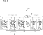
- Fig. 5 is a schematic configuration diagram illustrating an air-conditioning system 100A according to Embodiment 2.
- Embodiment 2 is different from Embodiment 1 in that the load device 2 has a supply-air temperature sensor 25 and a flow control valve 26.
- the same components as those in Embodiment 1 are denoted by the same reference signs, and therefore descriptions thereof are omitted.
- the different points from Embodiment 1 are mainly described below.
- the load device 2a has a supply-air temperature sensor 25a and a flow control valve 26a.
- the load device 2b has a supply-air temperature sensor 25b and a flow control valve 26b.
- the supply-air temperature sensor 25 measures a temperature of air to be sent from the load device 2 to an air-conditioning target space.
- the temperature of air to be sent from the load device 2 to the air-conditioning target space may be described as "supply-air temperature”.
- the flow control valve 26 is, for example, a two-way valve. An opening degree of the flow control valve 26 is controlled by the load side controller 23, so that the flow control valve 26 controls the flow rate of a heat medium flowing through the load device 2.
- the bypass pipe 41 has a function of avoiding the heat medium circuit 34 from being closed when both the flow control valves 26 are set at a full close opening degree.
- the load side controller 23 controls the flow control valve 26 in addition to the load side air-sending device 22.
- the load side controller 23 is connected to the flow control valve 26 with a wire or wirelessly.
- the load side controller 23 outputs a control signal for controlling the flow control valve 26 to the flow control valve 26.
- Fig. 6 is a functional block diagram illustrating the integrated controller 3 according to Embodiment 2.
- the load side instruction unit 74 in the integrated controller 3 indirectly controls the flow control valve 26 when an air-conditioning system 100A performs trial operation, and also when the air-conditioning system 100A performs actual operation.
- operation of the load side instruction unit 74 when the air-conditioning system 100A performs trial operation is described.
- the load side instruction unit 74 transmits an instruction signal to the load side controller 23 such that the opening degree of the flow control valve 26 is fixed.
- the opening degree is fixed at, for example, a full open opening degree.
- the load side controller 23 in the load device 2 having received the instruction signal, transmits a control signal to the flow control valve 26 such that the flow control valve 26 is fixed at the opening degree indicated by the instruction signal.
- the flow control valve 26 having received the control signal is fixed at the opening degree indicated by the control signal.
- the load side instruction unit 74 in the integrated controller 3 obtains a supply-air temperature from the supply-air temperature sensor 25.
- the load side instruction unit 74 determines an opening degree of the flow control valve 26 based on the obtained supply-air temperature.
- the flow control valve 26 is set at such an opening degree that the supply-air temperature becomes close to the set temperature.
- the load side instruction unit 74 transmits an instruction signal indicating the determined opening degree of the flow control valve 26 to the load side controller 23.
- the load side controller 23 in the load device 2 having received the instruction signal, transmits a control signal to the flow control valve 26 such that the flow control valve 26 operates at the opening degree indicated by the instruction signal.
- the flow control valve 26 having received the control signal is fixed at the opening degree indicated by the control signal.
- Fig. 7 is a flowchart illustrating operation of the integrated controller 3 according to Embodiment 2.
- the procedure for creating the Cv value table during trial operation in Embodiment 2 is different from the procedure for creating the Cv value table during trial operation in Embodiment 1 only in that the opening degree of the flow control valve 26 is fixed (step S21) prior to fixing the opening degree of the bypass valve 43 at a full close opening degree (step S1).
- the processes in steps S1 to S12 in Embodiment 2 are the same as those in Embodiment 1, and therefore descriptions thereof are omitted.
- the heat source side flow rate may be measured by a device configured to measure a pressure difference between the pressures upstream and downstream of the heat medium heat exchanger 14 in each heat source device 1, instead of the flow meter 51.
- a flow rate of the heat source devices 1 is proportional to the one-half power of the pressure difference between the upstream and downstream pressures
- the heat source side flow rate that is a total flow rate of the heat source devices 1 is acquired.
- a proportionality coefficient is determined by tests or the like during the design phase.
- the second pipe 33 is provided with the flow meter 51 configured to measure a flow rate of a heat medium flowing out from the load side to the heat source side.
- the pressure difference regulation unit 72 may control the opening degree of the bypass valve 43, giving priority to the control stability as an emergency measure, such that the bypass valve 43 is opened at a highest possible speed.
- the functions of the integrated controller 3, the heat source side controller 17, and the load side controller 23 are not limited to those described in Embodiments 1 and 2.
- some of the functions of the integrated controller 3, some the functions of the heat source side controllers 17, and some of the functions of the load side controllers 23 may be implemented by other devices.
- Two or more of the integrated controller 3, the heat source side controllers 17, and the load side controllers 23 may be integrated into a single device.
- the integrated controller 3, each of the heat source side controllers 17, or each of the load side controllers 23 may be made up of two or more devices. In any of the cases, one or more devices configured to directly or indirectly control the heat source device 1 and the bypass valve 43 are equivalent to "controller" of the present disclosure.
- the load side controller 23 in each load device 2 may operate each device to be controlled by the load side controller 23 by being directly manipulated by an installation worker, instead of operating each device to be controlled by the load side controller 23 based on an instruction signal from the integrated controller 3.
- the flow control valves 26 in Embodiment 2 are fixed at a full open opening degree by an installation worker manipulating the load side controllers 23 during trial operation.
- the refrigerant circuit 18 may be provided with a flow switching valve or other device to cause refrigerant to flow through the refrigerant circuit 18 in the reverse direction, thereby to heat the heat medium.
- Embodiments 1 and 2 an example in which the operating frequency of each pump 16 is fixed at the time of creating the Cv value table has been described.
- the operating frequency of each pump 16 may be varied to the extent not affecting the heat source side flow rate or the bypass pressure difference. For example, provided that there are no variations in the heat source side flow rate and the bypass pressure difference, the operating frequency of the pump 16a may be increased, while the operating frequency of the pump 16b may be decreased.
- the maximum value of Cv value gradient may be referenced to control the opening degree of the bypass valve 43, or the Cv value gradient corresponding to an opening degree of the bypass valve 43 at the control time point may be referenced to control the opening degree of the bypass valve 43.
- the time required for trial operation can be reduced, compared to the case when the Cv value table is created based on actual measurement results of the heat source side flow rate and the bypass pressure difference.
- 1, 1a, 1b, 1c heat source device, 2, 2a, 2b: load device, 3: integrated controller, 10, 10a, 10b, 10c: compressor, 11, 11a, 11b, 11 c: heat source side heat exchanger, 12, 12a, 12b, 12c: heat source side air-sending device, 13, 13a, 13b, 13c: expansion valve, 14, 14a, 14b, 14c: heat medium heat exchanger, 15, 15a, 15b, 15c: refrigerant pipe, 16, 16a, 16b, 16c: pump, 17, 17a, 17b, 17c: heat source side controller, 18, 18a, 18b, 18c: refrigerant circuit, 21, 21a, 21b: load side heat exchanger, 22, 22a, 22b: load side air-sending device, 23, 23a, 23b: load side controller, 24, 24a, 24b: return-air temperature sensor, 25, 25a, 25b: supply-air temperature sensor, 26, 26a, 26b: flow control valve, 31: heat medium pipe, 32: first pipe, 33:
Landscapes
- Engineering & Computer Science (AREA)
- Chemical & Material Sciences (AREA)
- Combustion & Propulsion (AREA)
- Mechanical Engineering (AREA)
- General Engineering & Computer Science (AREA)
- Air Conditioning Control Device (AREA)
Abstract
Description
- The present disclosure relates to an air-conditioning system having a bypass valve.
- A conventional air-conditioning system has been known in which a heat source device and a load device are connected by an outgoing-side pipe toward the load device and a return-side pipe from the load device. In this air-conditioning system, a bypass pipe is provided between the outgoing-side pipe and the return-side pipe, and a bypass valve is attached to the bypass pipe.
Patent Literature 1 discloses such an air-conditioning system as described above, that is configured to control a pump or a bypass valve provided at a bypass pipe such that a pressure difference between an outgoing pipe and a return pipe falls within a target range. - Patent Literature 1: International Publication No.
WO 2018/225221 - In general, such an air-conditioning system as disclosed in
Patent Literature 1 controls the bypass valve based on specifications of the bypass valve. Accordingly, an air-conditioning system having a bypass valve is required to load specification values of the bypass valve into a controller configured to control the bypass valve. Therefore, installation of the air-conditioning system is burdensome. In the current market, although the controller is provided in a heat source device, specifications of the bypass valve may be selected by an instrumentation provider separate from a manufacturer of the heat source device. In this case, the specification values of the bypass valve need to be manually loaded into the controller at the installation site of the air-conditioning system. This particularly makes the installation of the air-conditioning system burdensome. - The present disclosure has been made to solve the above problems, and it is an object of the present disclosure to provide an air-conditioning system having a bypass valve and making installation of the air-conditioning system efficient.
- An air-conditioning system according to an embodiment of the present disclosure is an air-conditioning system configured to circulate a heat medium through a heat medium circuit to exchange heat between the heat medium and air in an air-conditioning target space to condition air in the air-conditioning target space, the air-conditioning system including: a load device configured to exchange heat between air in the air-conditioning target space and the heat medium flowing through the heat medium circuit; a heat source device configured to exchange heat between refrigerant flowing through a refrigerant circuit and the heat medium flowing through the heat medium circuit, and deliver the heat medium cooled or heated through the heat medium circuit to the load device; a first pipe that connects the heat source device and the load device and through which the heat medium flows from the heat source device to the load device; a second pipe that connects the load device and the heat source device and through which the heat medium flows from the load device to the heat source device; a bypass pipe connecting the first pipe with the second pipe; a pressure difference gauge provided at the bypass pipe and configured to measure a bypass pressure difference being a pressure difference between the heat medium flowing through the first pipe and the heat medium flowing through the second pipe; a bypass valve provided at the bypass pipe and configured to control a flow rate of the heat medium flowing through the bypass pipe; and a controller configured to control operation of the heat source device and the bypass valve, the controller being configured to fix the opening degree of the bypass valve at a full close opening degree and acquire the heat source side flow rate and the bypass pressure difference, the heat source side flow rate and the bypass pressure difference being measured when the bypass valve is set at the full close opening degree, fix the opening degree of the bypass valve at a full open opening degree, fix the opening degree of the bypass valve at a full close opening degree and acquire a heat source side flow rate indicating a flow rate of the heat medium flowing through the heat source device and the bypass pressure difference being measured by the pressure difference gauge, the heat source side flow rate and the bypass pressure difference being measured when the bypass valve is set at the full close opening degree, and calculate a Cv value of the bypass valve when the opening degree of the bypass valve is at the full open opening degree based on the bypass pressure difference and the heat source side flow rate measured when the bypass valve is set at the full close opening degree and the bypass pressure difference and the heat source side flow rate measured when the bypass valve is set at the full open opening degree. Advantageous Effects of Invention
- According to an embodiment of the present disclosure, the integrated controller calculates a Cv value of the bypass valve when the opening degree of the bypass valve is at the full open opening degree based on the bypass pressure difference and the heat source side flow rate measured when the bypass valve is set at the full close opening degree, and the bypass pressure difference and the heat source side flow rate measured when the bypass valve is set at the full open opening degree. As described above, in the air-conditioning system according to an embodiment of the present disclosure, specification values of the bypass valve are automatically loaded into the controller. This can make installation of the air-conditioning system efficient.
-
- [
Fig. 1] Fig. 1 is a schematic configuration diagram illustrating an air-conditioning system according toEmbodiment 1. - [
Fig. 2] Fig. 2 is a functional block diagram illustrating a heat source side controller according toEmbodiment 1. - [
Fig. 3] Fig. 3 is a functional block diagram illustrating an integrated controller according toEmbodiment 1. - [
Fig. 4] Fig. 4 is a flowchart illustrating operation of the integrated controller according toEmbodiment 1. - [
Fig. 5] Fig. 5 is a schematic configuration diagram illustrating an air-conditioning system according to Embodiment 2. - [
Fig. 6] Fig. 6 is a functional block diagram illustrating the integrated controller according to Embodiment 2. - [
Fig. 7] Fig. 7 is a flowchart illustrating operation of the integrated controller according to Embodiment 2. -
Fig. 1 is a schematic configuration diagram illustrating an air-conditioning system 100 according toEmbodiment 1. As illustrated inFig. 1 , the air-conditioning system 100 hasheat source devices load devices controller 3, and aheat medium pipe 31. Theheat source devices load devices heat source devices load devices heat source devices heat source device 1" with the suffixes "a," "b," and "c" omitted from their reference numerals when theheat source devices load devices load devices heat source device 1 and the load device 2 will be described later. It suffices that one or moreheat source devices 1 and one or more load devices 2 are provided. - The integrated
controller 3 controls theheat source devices 1 and the load devices 2. Theheat medium pipe 31 connects in parallel to theheat source devices 1 and the load devices 2. Theheat source devices 1 and the load devices 2 are connected by theheat medium pipe 31, thereby forming aheat medium circuit 34 through which a heat medium circulates. Hereinafter, one side of theheat medium circuit 34 near theheat source device 1 may be described as "heat source side." In addition, the other side of theheat medium circuit 34 near the load device 2 may be described as "load side." - The
heat medium pipe 31 has afirst pipe 32 and asecond pipe 33. Thefirst pipe 32 is an outgoing-water header pipe that connects theheat source devices 1 and the load devices 2, and through which a heat medium flows from theheat source devices 1 to the load devices 2. Thesecond pipe 33 is a return-water header pipe that connects the load devices 2 and theheat source devices 1, and through which a heat medium flows from the load devices 2 to theheat source devices 1. - The air-
conditioning system 100 has abypass pipe 41, apressure difference gauge 42, and abypass valve 43. Thebypass pipe 41 is connected to thefirst pipe 32 and thesecond pipe 33. Thebypass pipe 41 is provided between theheat source devices 1 and the load devices 2 in parallel to theheat source devices 1 and the load devices 2. A heat medium having flowed through the heat source side of thefirst pipe 32 partially flows through thebypass pipe 41. The heat medium having flowed through thebypass pipe 41 flows out to the heat source side of thesecond pipe 33. Thepressure difference gauge 42 is provided at thebypass pipe 41. Thepressure difference gauge 42 measures a bypass pressure difference. The bypass pressure difference refers to a pressure difference between a heat medium flowing through thefirst pipe 32 from the heat source side into the load side, and a heat medium flowing out through thesecond pipe 33 from the load side to the heat source side. An opening degree of thebypass valve 43 is controlled by the integratedcontroller 3, so that thebypass valve 43 controls the flow rate of a heat medium flowing through thebypass pipe 41. - The air-
conditioning system 100 has aflow meter 51 and a delivery-water temperature sensor 52. Theflow meter 51 is provided at thefirst pipe 32 upstream of its connection location with thebypass pipe 41, that is, on the heat source side. Theflow meter 51 measures a heat source side flow rate. The heat source side flow rate indicates a total flow rate of a heat medium flowing through theheat source devices 1. In a case where only a singleheat source device 1 is provided, the heat source side flow rate indicates a flow rate of a heat medium flowing through the singleheat source device 1. The delivery-water temperature sensor 52 is provided at thefirst pipe 32 on the heat source side relative to its connection location with thebypass pipe 41. The delivery-water temperature sensor 52 measures a temperature of a heat medium to be delivered from the heat source side to the load side. Hereinafter, the temperature of a heat medium to be delivered from the heat source side to the load side may be described as "delivery-water temperature." - The
pressure difference gauge 42, theflow meter 51, and the delivery-water temperature sensor 52 are connected to theintegrated controller 3 with a wire or wirelessly to communicate with theintegrated controller 3. Thepressure difference gauge 42 transmits information indicating a bypass pressure difference to theintegrated controller 3. Theflow meter 51 transmits information indicating the heat source side flow rate to theintegrated controller 3. The delivery-water temperature sensor 52 transmits information on a delivery-water temperature to theintegrated controller 3. - Next, the
heat source devices 1 are described. Theheat source device 1a includes, in a housing illustrated by the dotted line, acompressor 10a, a heat source side heat exchanger 11a, a heat source side air-sendingdevice 12a, anexpansion valve 13a, a heatmedium heat exchanger 14a, arefrigerant pipe 15a, apump 16a, and a heatsource side controller 17a. Thecompressor 10a, the heat source side heat exchanger 11a, theexpansion valve 13a, and the heatmedium heat exchanger 14a are connected sequentially by therefrigerant pipe 15a, forming arefrigerant circuit 18a through which refrigerant circulates. The heatmedium heat exchanger 14a and thepump 16a are connected by theheat medium pipe 31. - Similarly to the above, the
heat source device 1b includes, in a housing illustrated by the dotted line, acompressor 10b, a heat source side heat exchanger 11b, a heat source side air-sendingdevice 12b, anexpansion valve 13b, a heat medium heat exchanger 14b, arefrigerant pipe 15b, apump 16b, and a heatsource side controller 17b. Thecompressor 10b, the heat source side heat exchanger 11b, theexpansion valve 13b, and the heat medium heat exchanger 14b are connected sequentially by therefrigerant pipe 15b, forming arefrigerant circuit 18b through which refrigerant circulates. The heat medium heat exchanger 14b and thepump 16b are connected by theheat medium pipe 31. - Similarly to the above, the
heat source device 1c includes, in a housing illustrated by the dotted line, acompressor 10c, a heat source side heat exchanger 11c, a heat source side air-sendingdevice 12c, an expansion valve 13c, a heat medium heat exchanger 14c, a refrigerant pipe 15c, apump 16c, and a heatsource side controller 17c. Thecompressor 10c, the heat source side heat exchanger 11c, the expansion valve 13c, and the heat medium heat exchanger 14c are connected sequentially by the refrigerant pipe 15c, forming arefrigerant circuit 18c through which refrigerant circulates. The heat medium heat exchanger 14c and thepump 16c are connected by theheat medium pipe 31. As described above, theheat source devices 1 all have an identical configuration, and thus constituent components included in theheat source devices 1 may also be described with the suffixes "a," "b," and "c" omitted from their reference numerals. - The
compressor 10 suctions refrigerant from the refrigerant pipe 15, compresses the suctioned refrigerant, and discharges the compressed refrigerant to the refrigerant pipe 15. Thecompressor 10 is an inverter compressor whose capacity is controllable by an inverter. Through the heat source side heat exchanger 11, heat is exchanged between refrigerant and air delivered by the heat source side air-sendingdevice 12. Examples of the heat source side air-sendingdevice 12 include a propeller fan, a turbo fan, and a sirocco fan. The heat source side air-sendingdevice 12 guides air in a space, other than an air-conditioning target space where the load device 2 is provided, to the heat source side heat exchanger 11. - The
expansion valve 13 reduces a pressure of refrigerant flowing from the heat source side heat exchanger 11, and expands the refrigerant. Theexpansion valve 13 is, for example, an electric expansion valve capable of controlling the flow rate of refrigerant. The heat medium heat exchanger 14 is, for example, a plate heat exchanger through which heat is exchanged between refrigerant flowing through the refrigerant circuit 18 and a heat medium flowing through theheat medium circuit 34. In the heat medium heat exchanger 14, a heat medium is cooled by exchanging heat with refrigerant. - The
pump 16 is configured to circulate a heat medium through theheat medium circuit 34. Thepump 16 is configured to adjust the flow rate of a heat medium by varying the operating frequency through the inverter. - The heat
source side controller 17 is made up of dedicated hardware, or a storage device (not illustrated) and a central processing unit (CPU) configured to execute programs stored in the storage device. The heatsource side controller 17 controls thecompressor 10, the heat source side air-sendingdevice 12, theexpansion valve 13, and thepump 16. The heatsource side controller 17 is connected to thecompressor 10, the heat source side air-sendingdevice 12, theexpansion valve 13, and thepump 16 with a wire or wirelessly. The heatsource side controller 17 outputs a control signal for controlling thecompressor 10, the heat source side air-sendingdevice 12, theexpansion valve 13, and thepump 16 to the target devices through wired communication or wireless communication. The heatsource side controller 17 is connected to theintegrated controller 3 with a wire or wirelessly and communicates with theintegrated controller 3. -
Fig. 2 is a functional block diagram illustrating the heatsource side controller 17 according toEmbodiment 1. As illustrated inFig. 2 , the heatsource side controller 17 has a refrigerantcircuit control unit 61 and apump control unit 62. The refrigerantcircuit control unit 61 and thepump control unit 62 are implemented by, for example, software, firmware, or a combination of the software and the firmware. The refrigerantcircuit control unit 61 receives, from theintegrated controller 3, an instruction signal including information that indicates an operating frequency of thecompressor 10, an operating frequency of the heat source side air-sendingdevice 12, and an opening degree of theexpansion valve 13. Based on the instruction signal received from theintegrated controller 3, the refrigerantcircuit control unit 61 controls thecompressor 10, the heat source side air-sendingdevice 12, and theexpansion valve 13. Specifically, when the instruction signal includes information on an operating frequency of thecompressor 10, the refrigerantcircuit control unit 61 transmits a control signal to thecompressor 10 such that thecompressor 10 operates at the operating frequency. When the instruction signal includes information on an operating frequency of the heat source side air-sendingdevice 12, the refrigerantcircuit control unit 61 transmits a control signal to the heat source side air-sendingdevice 12 such that the heat source side air-sendingdevice 12 operates at the operating frequency. When the instruction signal includes information on an opening degree of theexpansion valve 13, the refrigerantcircuit control unit 61 transmits a control signal to theexpansion valve 13 such that its opening degree is fixed at the indicated opening degree. - The
pump control unit 62 receives an instruction signal indicating an operating frequency of thepump 16 from theintegrated controller 3. Thepump control unit 62 controls thepump 16 based on the instruction signal received from theintegrated controller 3. Specifically, when receiving the instruction signal, thepump control unit 62 transmits a control signal to thepump 16 such that thepump 16 operates at the operating frequency indicated by the instruction signal. - Next, referring back to
Fig. 1 , the load devices 2 are described. The load device 2 includes a load side heat exchanger 21a, a load side air-sendingdevice 22a, aload side controller 23a, and a return-air temperature sensor 24a. Likewise, theload device 2b includes a loadside heat exchanger 21b, a load side air-sendingdevice 22b, aload side controller 23b, and a return-air temperature sensor 24b. As described above, the load devices 2 both have an identical configuration, and thus constituent components included in the load devices 2 may also be described with the suffixes "a" and "b" omitted from their reference numerals. - Through the load side heat exchanger 21, heat is exchanged between air delivered by the load side air-sending device 22 and a heat medium flowing through the
heat medium circuit 34. Examples of the load side air-sending device 22 include a propeller fan, a turbo fan, and a sirocco fan. The load side air-sending device 22 guides air in an air-conditioning target space to the load side heat exchanger 21. - The
load side controller 23 is made up of dedicated hardware, or a storage device (not illustrated) and a central processing unit (CPU) configured to execute programs stored in the storage device. Theload side controller 23 controls the load side air-sending device 22. Theload side controller 23 is connected to the load side air-sending device 22 with a wire or wirelessly, and transmits a control signal for controlling the load side air-sending device 22 to the load side air-sending device 22. Theload side controller 23 is connected to theintegrated controller 3 with a wire or wirelessly and communicates with theintegrated controller 3. - The
load side controller 23 receives, from theintegrated controller 3, an instruction signal including information that indicates an operating frequency of the load side air-sending device 22. Based on the received instruction signal, theload side controller 23 controls the load side air-sending device 22. Specifically, when receiving the instruction signal, theload side controller 23 transmits a control signal to the load side air-sending device 22 such that the load side air-sending device 22 operates at the operating frequency indicated by the instruction signal. - The return-
air temperature sensor 24 measures a temperature of air to be guided from an air-conditioning target space to the load device 2. Hereinafter, the temperature of air to be guided from the air-conditioning target space to the load device 2 may be described as "return-air temperature." The return-air temperature sensor 24 is connected to theintegrated controller 3 with a wire or wirelessly to communicate with theintegrated controller 3. The return-air temperature sensor 24 transmits information indicating a return-air temperature to theintegrated controller 3. Note that the return-air temperature sensor 24 may communicate with theintegrated controller 3 through theload side controller 23. - Next, the
integrated controller 3 is described.Fig. 3 is a functional block diagram illustrating theintegrated controller 3 according toEmbodiment 1. As illustrated inFig. 3 , theintegrated controller 3 has acalculation unit 71, a pressuredifference regulation unit 72, a refrigerantcircuit instruction unit 73, a loadside instruction unit 74, and astorage unit 75. - The
calculation unit 71 creates a Cv value table in which each opening degree of thebypass valve 43 is associated with a Cv value of thebypass valve 43 fixed at each opening degree when the air-conditioning system 100 performs trial operation. Note that the Cv value indicates how easily fluid flows through a valve. A larger Cv value indicates a smaller pressure loss and indicates that fluid flows through the valve more easily. - The
calculation unit 71 creates the Cv value table in the following manner. First, thecalculation unit 71 calculates a heat source side flow rate Q(0) [m3/h] from a measurement result of theflow meter 51 when the opening degree of thebypass valve 43 is 0%, that is, set at a full close opening degree with eachpump 16 operating at a fixed frequency. Similarly to the above, thecalculation unit 71 calculates a bypass pressure difference ΔP(0) [kPa] from a measurement result of thepressure difference gauge 42. Further, zero is stored in a Cv value Cv(0). Note that a figure in parentheses indicates an opening degree of thebypass valve 43. That is, when the opening degree is i%, the heat source side flow rate is represented as Q(i), the bypass pressure difference is represented as ΔP(i), and the Cv value is represented as Cv(i). - Next, the
calculation unit 71 calculates a total pressure loss in thebypass pipe 41 and theload devices calculation unit 71 substitutes the heat source side flow rate Q(0) and the bypass pressure difference ΔP(0) in Expression (1) to calculate the pressure loss coefficient R(0).
- Subsequently, the
calculation unit 71 obtains the heat source side flow rate Q(1) and the bypass pressure difference ΔP(1) respectively from theflow meter 51 and thepressure difference gauge 42 when the opening degree of thebypass valve 43 is fixed at 1%. Thecalculation unit 71 substitutes the heat source side flow rate Q(1) and the bypass pressure difference ΔP(1) in the above Expression (1) to calculate a pressure loss coefficient R(1). - The
calculation unit 71 calculates a Cv value Cv(1) when the valve opening degree is 1%. When the valve opening degree is i%, the bypass flow rate Q1(i) at which fluid flows through thebypass pipe 41 is expressed as the following Expression (2). When the valve opening degree is i%, a load side flow rate Q2(i) that indicates a total flow rate of a heat medium flowing through the load side is expressed as Expression (3).

- Since the heat source side flow rate Q(i) is equal to the sum of Q1(i) and Q2(i), the following Expression (4) can be derived from Expressions (1) to (3).

- The
calculation unit 71 substitutes the pressure loss coefficient R(0) obtained when the valve opening degree is a full close opening degree, and the pressure loss coefficient R(1) obtained when the valve opening degree is 1% in Expression (4) to calculate a Cv value Cv(1). Thecalculation unit 71 calculates a Cv value each time the valve opening degree varies in increments of 1% from 1% to 100%. Thecalculation unit 71 stores a Cv value table in thestorage unit 75. In the Cv value table, Cv(0) with the value "zero" stored therein and calculated Cv(i) are associated with respective valve opening degrees "i." Note that the pressure loss coefficient R(i) is a value derived from measurement values measured by theflow meter 51 and thepressure difference gauge 42 as expressed by Expression (1). Accordingly, in Expression (4), Cv(i) may be calculated by using the heat source side flow rate Q(0) and the bypass pressure difference ΔP(0) instead of the pressure loss coefficient R(0), and using the heat source side flow rate Q(i) and the bypass pressure difference ΔP(i) instead of the pressure loss coefficient R(i). - The pressure
difference regulation unit 72 controls thebypass valve 43 and thepump 16 when the air-conditioning system 100 performs trial operation, and also when the air-conditioning system 100 performs actual operation. First, operation of the pressuredifference regulation unit 72 when the air-conditioning system 100 performs trial operation is described. When the Cv value table is created during trial operation, the pressuredifference regulation unit 72 transmits an instruction signal to thepump control unit 62 in each heatsource side controller 17 such that each pump 16 operate at a fixed frequency. The fixed frequency is, for example, a rated frequency that satisfies a rated flow rate of the load device 2 requested by an administrator or other user of the air-conditioning system 100. When receiving the instruction signal, thepump control unit 62 in each heatsource side controller 17 transmits a control signal to each pump 16 such that thepump 16 operates at an operating frequency indicated by the instruction signal. When the Cv value table is created during trial operation, the pressuredifference regulation unit 72 transmits a control signal to thebypass valve 43 to increase the valve opening degree in increments of 1%. - Next, operation of the pressure
difference regulation unit 72 when the air-conditioning system 100 performs actual operation is described. The pressuredifference regulation unit 72 controls thepump 16 and thebypass valve 43 in conjunction with each other such that the bypass pressure difference becomes a target value. For example, when the bypass pressure difference is below the target value at the control time point, the pressuredifference regulation unit 72 gives higher priority to controlling thebypass valve 43 to be throttled than controlling thepump 16 to increase its speed. For another example, when the bypass pressure difference exceeds the target value at the control time point, the pressuredifference regulation unit 72 gives higher priority to controlling thepump 16 to decrease its speed than controlling thebypass valve 43 to be opened. In this manner, based on a comparison result between the value of bypass pressure difference at the control time point and a target value, the pressuredifference regulation unit 72 transmits an instruction signal to thepump control unit 62 in each heatsource side controller 17 or transmits a control signal to thebypass valve 43. Thepump 16 and thebypass valve 43 are exclusively controlled in the manner as described above, so that the air-conditioning system 100 improves its energy efficiency. - Control of the
bypass valve 43 is described below in detail. The pressuredifference regulation unit 72 executes, for example, a commonly-called I-control, PI-control, or PID control to control thebypass valve 43 such that the bypass pressure difference ΔP becomes a target value. In these controls, the pressuredifference regulation unit 72 determines an amount of change [%] in the opening degree of thebypass valve 43 according to a deviation ΔΔP of the bypass pressure difference ΔP from a control target value (=current value of the bypass pressure difference ΔP - target value of the bypass pressure difference ΔP). The amount of change in the opening degree of thebypass valve 43 is determined using a control coefficient that is inversely proportional to a process gain. The process gain is a value obtained by dividing a controlled amount by a manipulated amount when the opening degree of thebypass valve 43 is varied in steps. The controlled amount is equivalent to an amount of change in the bypass pressure difference ΔP, while the manipulated amount is equivalent to the amount of change in the opening degree of thebypass valve 43. - In a case where a predetermined number of
heat source devices 1 are used, it is possible to determine the amount of change in the bypass pressure difference ΔP associated with a Cv value gradient during the design phase based on the characteristics of thepump 16 determined by the flow rate perpump 16 and the bypass pressure difference ΔP. The Cv value gradient indicates a degree of variation in the Cv value when the opening degree of thebypass valve 43 is varied. The amount of change in the bypass pressure difference ΔP is varied according to the value of the Cv value gradient. Accordingly, the amount of change in the bypass pressure difference ΔP associated with the Cv value gradient, and stored in thestorage unit 75 as a design value, is multiplied by the value of Cv value gradient, thereby to acquire the amount of change in the bypass pressure difference ΔP corresponding to the amount of change in the opening degree of thebypass valve 43. As described above, the amount of change in the bypass pressure difference ΔP corresponding to the amount of change in the opening degree of thebypass valve 43 is equivalent to the process gain. Based on the calculated process gain, a control coefficient that determines an amount of change in the opening degree of thebypass valve 43, and the amount of change in the opening degree of thebypass valve 43 are acquired. - In
Embodiment 1, the Cv value gradient is calculated based on the Cv value table calculated during trial operation. Specifically, the pressuredifference regulation unit 72 acquires the process gain by using a maximum value of Cv value gradient among the Cv value gradients calculated for respective opening degrees in the Cv value table, that is, Cv(i) - Cv(i-1) (i: 0 to 100). - The refrigerant
circuit instruction unit 73 operates in the following manner when the air-conditioning system 100 performs actual operation. That is, the refrigerantcircuit instruction unit 73 obtains a delivery-water temperature from the delivery-water temperature sensor 52. The refrigerantcircuit instruction unit 73 determines an operating frequency of thecompressor 10 such that the delivery-water temperature becomes a target temperature. The refrigerantcircuit instruction unit 73 transmits an instruction signal indicating the operating frequency of thecompressor 10 to the refrigerantcircuit control unit 61 in the heatsource side controller 17 of theheat source device 1 to be controlled. The heatsource side controller 17 in theheat source device 1, having received the instruction signal, transmits a control signal to thecompressor 10 such that thecompressor 10 operates at the operating frequency indicated by the instruction signal. Thecompressor 10 having received the control signal operates at the frequency indicated by the control signal. - The load
side instruction unit 74 operates in the following manner when the air-conditioning system 100 performs actual operation. That is, the loadside instruction unit 74 obtains a return-air temperature from the return-air temperature sensor 24. The loadside instruction unit 74 determines an operating frequency of the load side air-sending device 22 based on a difference between the obtained return-air temperature and a set temperature. The loadside instruction unit 74 transmits an instruction signal indicating the determined operating frequency of the load side air-sending device 22 to theload side controller 23. Theload side controller 23 in the load device 2, having received the instruction signal, transmits a control signal to the load side air-sending device 22 such that the load side air-sending device 22 operates at the operating frequency indicated by the instruction signal. The load side air-sending device 22 having received the control signal operates at the operating frequency indicated by the control signal. - The
storage unit 75 has various types of design values stored therein to be used for controlling the air-conditioning system 100, such as the amount of change in the bypass pressure difference ΔP associated with the Cv value gradient. During trial operation of the air-conditioning system 100, thestorage unit 75 stores therein the Cv value table created by thecalculation unit 71. - The
integrated controller 3 is made up of dedicated hardware, or thestorage unit 75 and a central processing unit (CPU) configured to execute programs stored in thestorage unit 75. When theintegrated controller 3 is dedicated hardware, theintegrated controller 3 is equivalent to, for example, a single circuit, a combined circuit, an application specific integrated circuit (ASIC), a field-programmable gate array (FPGA), or a combination thereof. The functional units of theintegrated controller 3 may be individually implemented by separate units of hardware, or the functional units of theintegrated controller 3 may be implemented together by a single unit of hardware. - When the
integrated controller 3 is a CPU, the functional units to be executed by theintegrated controller 3 are implemented by software, firmware, or a combination of the software and the firmware. The software and the firmware are described as programs and stored in thestorage unit 75. The CPU reads and executes the programs stored in thestorage unit 75, and thereby implements the functional units of theintegrated controller 3. For example, thestorage unit 75 is a nonvolatile or volatile semiconductor memory such as a RAM, a ROM, a flash memory, an EPROM, or an EEPROM. Note that the functions of theintegrated controller 3 may be partially implemented by dedicated hardware, while being partially implemented by software or firmware. -
Fig. 4 is a flowchart illustrating operation of theintegrated controller 3 according toEmbodiment 1. With reference toFig. 4 , the procedure for creating the Cv value table during trial operation is described below. First, the pressuredifference regulation unit 72 fixes the opening degree of thebypass valve 43 at a full close opening degree (step S1). The pressuredifference regulation unit 72 fixes the frequency of each pump 16 (step S2). With the frequency of each pump 16 fixed at a predetermined frequency, and the opening degree of thebypass valve 43 fixed at a full close opening degree, thecalculation unit 71 obtains the heat source side flow rate Q(0) from the flow meter 51 (step S3). Thecalculation unit 71 obtains the bypass pressure difference ΔP(0) from the pressure difference gauge 42 (step S4). Thecalculation unit 71 calculates the pressure loss coefficient R(0) (step S5), and stores zero in the Cv value Cv(0) (step S6). - Subsequently, the pressure
difference regulation unit 72 determines whether the valve opening degree "i" of thebypass valve 43 exceeds 100 (step S7). Note that zero is stored as an initial value of the valve opening degree "i." When the valve opening degree "i" of thebypass valve 43 is equal to or smaller than 100 (step S7: NO), the pressuredifference regulation unit 72 adds 1 to the valve opening degree "i," that is, increases the opening degree of thebypass valve 43 by 1% (step S8). With the valve opening degree increased by 1% and fixed, thecalculation unit 71 obtains the heat source side flow rate Q(i) from the flow meter 51 (step S9). Thecalculation unit 71 obtains the bypass pressure difference ΔP(i) from the pressure difference gauge 42 (step S10). Thecalculation unit 71 calculates the pressure loss coefficient R(i) (step S11). - The
calculation unit 71 calculates the Cv value Cv(i), using the pressure loss coefficient R(0) and the pressure loss coefficient R(i) (step S12). Theintegrated controller 3 repeats the processes in steps S8 to S12 until the valve opening degree "i" exceeds 100 (step S7: YES). With this processing, theintegrated controller 3 completes the calculation of an opening degree of thebypass valve 43 and the Cv value of thebypass valve 43 fixed at each opening degree, where the opening degree of thebypass valve 43 is 1% to 100%. - In the manner as described above, the
integrated controller 3 creates the Cv value table by storing the value "zero" corresponding to the Cv value Cv(0) and having been stored in step S6, as well as an opening degree and each Cv value of thebypass valve 43 fixed at each opening degree in association with each valve opening degree "i." Note that in the above procedure for creating the Cv value table, the order of the steps may be changed appropriately to the extent not affecting the calculated Cv values. - According to
Embodiment 1, theintegrated controller 3 calculates a Cv value of thebypass valve 43 when the opening degree of thebypass valve 43 is at the full open opening degree based on the bypass pressure difference and the heat source side flow rate measured when thebypass valve 43 is set at the full close opening degree, and the bypass pressure difference and the heat source side flow rate measured when thebypass valve 43 is set at the full open opening degree. As described above, in the air-conditioning system 100 inEmbodiment 1, specification values of thebypass valve 43 are automatically loaded into theintegrated controller 3. This can make installation of the air-conditioning system 100 efficient. - In
Embodiment 1, theintegrated controller 3 creates the Cv value table. As described above, in the air-conditioning system 100 inEmbodiment 1, detailed specification values of thebypass valve 43 are automatically loaded into theintegrated controller 3. This makes installation of the air-conditioning system 100 even more efficient. In addition, it is possible to determine the control coefficient of thebypass valve 43 based on the characteristics of variations in the Cv value relative to variations in the opening degree of thebypass valve 43, so that the air-conditioning system 100 can improve its stability during actual operation. Note that examples of the characteristics described herein include linear characteristics, quick open characteristics, and equal percentage characteristics. The linear characteristics show that the Cv value varies linearly relative to variations in the opening degree of thebypass valve 43. The quick open characteristics show that the Cv value varies significantly when the opening degree of thebypass valve 43 varies within a range of low opening degree. The equal percentage characteristics show that the Cv value varies significantly when the opening degree of thebypass valve 43 varies within a range of high opening degree. - In
Embodiment 1, during actual operation, the process gain is acquired by using the maximum value of Cv value gradient among the Cv value gradients calculated for respective opening degrees in the Cv value table. As described above, the amount of change in the opening degree of thebypass valve 43 is determined using a coefficient that is inversely proportional to the process gain. The process gain is acquired by using the maximum value of Cv value gradient, and accordingly the amount of change in the opening degree is reduced. Consequently, even when the variations in the Cv value relative to the variations in the opening degree of thebypass valve 43 exhibit quick open characteristics or equal percentage characteristics, rather than linear characteristics, the opening degree of thebypass valve 43 can still be controlled in a stable manner. - In
Modification 1 ofEmbodiment 1, during actual operation, the process gain is acquired by using a value of Cv value gradient corresponding to an opening degree of thebypass valve 43 at the control time point among the values of Cv value gradient calculated for respective opening degrees in the Cv value table, that is, Cv(i) - Cv(i-1) (i: 0 to 100). For example, where an opening degree of thebypass valve 43 at the control time point is represented as j%, the Cv value gradient corresponding to the opening degree of thebypass valve 43 at the control time point is given as a Cv value gradient within a range of predetermined plus or minus k% of the median j%, that is, Cv(j+k) - Cv(j-k). - Also in
Modification 1 ofEmbodiment 1, specification values of thebypass valve 43 are automatically loaded into theintegrated controller 3. This can make installation of the air-conditioning system 100 efficient. It is also possible to control thebypass valve 43 with an optimal control coefficient according to the valve opening degree at the control time point. This helps the bypass pressure difference ΔP to follow the target value at the earliest possible time, while ensuring the stability of the air-conditioning system 100. - In Modification 2 of
Embodiment 1, only a Cv(100) is calculated during trial operation, instead of creating the Cv value table. During actual operation, based on the assumed type of characteristics of variations in the Cv value relative to variations in the opening degree of thebypass valve 43, the Cv value gradient is calculated to acquire the process gain. Specifically, when variations in the Cv value relative to variations in the opening degree of thebypass valve 43 are assumed to exhibit, for example, linear characteristics, the Cv value gradient is equivalent to Cv(100)/100. - Also in Modification 2 of
Embodiment 1, specification values of thebypass valve 43 are automatically loaded into theintegrated controller 3. This can make installation of the air-conditioning system 100 efficient. Only Cv(100) is calculated, so that the time required for trial operation can be reduced, compared to the case when the Cv value table is created. It is also possible for thestorage unit 75 to omit a storage area for storing the Cv value table. It is also allowable to control thebypass valve 43 in the manner as described above using the Cv value table created during trial operation. -
Fig. 5 is a schematic configuration diagram illustrating an air-conditioning system 100A according to Embodiment 2. As illustrated inFig. 5 , Embodiment 2 is different fromEmbodiment 1 in that the load device 2 has a supply-air temperature sensor 25 and a flow control valve 26. In Embodiment 2, the same components as those inEmbodiment 1 are denoted by the same reference signs, and therefore descriptions thereof are omitted. The different points fromEmbodiment 1 are mainly described below. - The
load device 2a has a supply-air temperature sensor 25a and aflow control valve 26a. Theload device 2b has a supply-air temperature sensor 25b and aflow control valve 26b. The supply-air temperature sensor 25 measures a temperature of air to be sent from the load device 2 to an air-conditioning target space. Hereinafter, the temperature of air to be sent from the load device 2 to the air-conditioning target space may be described as "supply-air temperature". - The flow control valve 26 is, for example, a two-way valve. An opening degree of the flow control valve 26 is controlled by the
load side controller 23, so that the flow control valve 26 controls the flow rate of a heat medium flowing through the load device 2. In a case where the flow control valves 26 are provided, thebypass pipe 41 has a function of avoiding theheat medium circuit 34 from being closed when both the flow control valves 26 are set at a full close opening degree. - The
load side controller 23 controls the flow control valve 26 in addition to the load side air-sending device 22. Theload side controller 23 is connected to the flow control valve 26 with a wire or wirelessly. Theload side controller 23 outputs a control signal for controlling the flow control valve 26 to the flow control valve 26. -
Fig. 6 is a functional block diagram illustrating theintegrated controller 3 according to Embodiment 2. As illustrated inFig. 6 , the loadside instruction unit 74 in theintegrated controller 3 indirectly controls the flow control valve 26 when an air-conditioning system 100A performs trial operation, and also when the air-conditioning system 100A performs actual operation. First, operation of the loadside instruction unit 74 when the air-conditioning system 100A performs trial operation is described. When the Cv value table is created during trial operation, the loadside instruction unit 74 transmits an instruction signal to theload side controller 23 such that the opening degree of the flow control valve 26 is fixed. The opening degree is fixed at, for example, a full open opening degree. Theload side controller 23 in the load device 2, having received the instruction signal, transmits a control signal to the flow control valve 26 such that the flow control valve 26 is fixed at the opening degree indicated by the instruction signal. The flow control valve 26 having received the control signal is fixed at the opening degree indicated by the control signal. - Next, operation of the load
side instruction unit 74 when the air-conditioning system 100A performs actual operation is described. The loadside instruction unit 74 in theintegrated controller 3 obtains a supply-air temperature from the supply-air temperature sensor 25. The loadside instruction unit 74 determines an opening degree of the flow control valve 26 based on the obtained supply-air temperature. The flow control valve 26 is set at such an opening degree that the supply-air temperature becomes close to the set temperature. The loadside instruction unit 74 transmits an instruction signal indicating the determined opening degree of the flow control valve 26 to theload side controller 23. Theload side controller 23 in the load device 2, having received the instruction signal, transmits a control signal to the flow control valve 26 such that the flow control valve 26 operates at the opening degree indicated by the instruction signal. The flow control valve 26 having received the control signal is fixed at the opening degree indicated by the control signal. -
Fig. 7 is a flowchart illustrating operation of theintegrated controller 3 according to Embodiment 2. As illustrated inFig. 7 , the procedure for creating the Cv value table during trial operation in Embodiment 2 is different from the procedure for creating the Cv value table during trial operation inEmbodiment 1 only in that the opening degree of the flow control valve 26 is fixed (step S21) prior to fixing the opening degree of thebypass valve 43 at a full close opening degree (step S1). The processes in steps S1 to S12 in Embodiment 2 are the same as those inEmbodiment 1, and therefore descriptions thereof are omitted. - While the embodiments and the modifications have been described above, it is possible to appropriately make a change to the air-
conditioning systems heat source device 1, instead of theflow meter 51. For example, assuming that a flow rate of theheat source devices 1 is proportional to the one-half power of the pressure difference between the upstream and downstream pressures, the heat source side flow rate that is a total flow rate of theheat source devices 1 is acquired. A proportionality coefficient is determined by tests or the like during the design phase. - It is also allowable that the
second pipe 33 is provided with theflow meter 51 configured to measure a flow rate of a heat medium flowing out from the load side to the heat source side. - For example, when the bypass pressure difference exceeds a predetermined value that is set larger than the target value, the pressure
difference regulation unit 72 may control the opening degree of thebypass valve 43, giving priority to the control stability as an emergency measure, such that thebypass valve 43 is opened at a highest possible speed. - The functions of the
integrated controller 3, the heatsource side controller 17, and theload side controller 23 are not limited to those described inEmbodiments 1 and 2. For example, some of the functions of theintegrated controller 3, some the functions of the heatsource side controllers 17, and some of the functions of theload side controllers 23 may be implemented by other devices. Two or more of theintegrated controller 3, the heatsource side controllers 17, and theload side controllers 23 may be integrated into a single device. Further, theintegrated controller 3, each of the heatsource side controllers 17, or each of theload side controllers 23 may be made up of two or more devices. In any of the cases, one or more devices configured to directly or indirectly control theheat source device 1 and thebypass valve 43 are equivalent to "controller" of the present disclosure. Note that during trial operation, theload side controller 23 in each load device 2 may operate each device to be controlled by theload side controller 23 by being directly manipulated by an installation worker, instead of operating each device to be controlled by theload side controller 23 based on an instruction signal from theintegrated controller 3. For example, the flow control valves 26 in Embodiment 2 are fixed at a full open opening degree by an installation worker manipulating theload side controllers 23 during trial operation. - In
Embodiments 1 and 2, an example in which theheat source device 1 cools a heat medium has been described. However, the refrigerant circuit 18 may be provided with a flow switching valve or other device to cause refrigerant to flow through the refrigerant circuit 18 in the reverse direction, thereby to heat the heat medium. - In
Embodiments 1 and 2, an example in which the operating frequency of eachpump 16 is fixed at the time of creating the Cv value table has been described. However, the operating frequency of eachpump 16 may be varied to the extent not affecting the heat source side flow rate or the bypass pressure difference. For example, provided that there are no variations in the heat source side flow rate and the bypass pressure difference, the operating frequency of thepump 16a may be increased, while the operating frequency of thepump 16b may be decreased. - In Modification 2 of
Embodiment 1, the case has been described in which the opening degree of thebypass valve 43 is controlled during actual operation, assuming that variations in the Cv value relative to variations in the opening degree of thebypass valve 43 exhibit linear characteristics. However, variations in the Cv value relative to variations in the opening degree of thebypass valve 43 may be assumed to exhibit characteristics other than the linear characteristics. Even when variations in the Cv value relative to variations in the opening degree of thebypass valve 43 exhibit, for example, quick open characteristics or equal percentage characteristics, computation expressions stored in advance in thestorage unit 75 may be referenced to complement the Cv value table based on a measured Cv value Cv(100). In this case, based on the complemented Cv value table, the maximum value of Cv value gradient may be referenced to control the opening degree of thebypass valve 43, or the Cv value gradient corresponding to an opening degree of thebypass valve 43 at the control time point may be referenced to control the opening degree of thebypass valve 43. In any of the cases, the time required for trial operation can be reduced, compared to the case when the Cv value table is created based on actual measurement results of the heat source side flow rate and the bypass pressure difference. - 1, 1a, 1b, 1c: heat source device, 2, 2a, 2b: load device, 3: integrated controller, 10, 10a, 10b, 10c: compressor, 11, 11a, 11b, 11 c: heat source side heat exchanger, 12, 12a, 12b, 12c: heat source side air-sending device, 13, 13a, 13b, 13c: expansion valve, 14, 14a, 14b, 14c: heat medium heat exchanger, 15, 15a, 15b, 15c: refrigerant pipe, 16, 16a, 16b, 16c: pump, 17, 17a, 17b, 17c: heat source side controller, 18, 18a, 18b, 18c: refrigerant circuit, 21, 21a, 21b: load side heat exchanger, 22, 22a, 22b: load side air-sending device, 23, 23a, 23b: load side controller, 24, 24a, 24b: return-air temperature sensor, 25, 25a, 25b: supply-air temperature sensor, 26, 26a, 26b: flow control valve, 31: heat medium pipe, 32: first pipe, 33: second pipe, 34: heat medium circuit, 41: bypass pipe, 42: pressure difference gauge, 43: bypass valve, 51: flow meter, 52: delivery-water temperature sensor, 61: refrigerant circuit control unit, 62: pump control unit, 71: calculation unit, 72: pressure difference regulation unit, 73: refrigerant circuit instruction unit, 74: load side instruction unit, 75: storage unit, 100, 100A: air-conditioning system
Claims (10)
- An air-conditioning system configured to circulate a heat medium through a heat medium circuit to exchange heat between the heat medium and air in an air-conditioning target space to condition air in the air-conditioning target space, the air-conditioning system comprising:a load device configured to exchange heat between air in the air-conditioning target space and the heat medium flowing through the heat medium circuit;a heat source device configured to exchange heat between refrigerant flowing through a refrigerant circuit and the heat medium flowing through the heat medium circuit, and deliver the heat medium cooled or heated through the heat medium circuit to the load device;a first pipe that connects the heat source device and the load device and through which the heat medium flows from the heat source device to the load device;a second pipe that connects the load device and the heat source device and through which the heat medium flows from the load device to the heat source device;a bypass pipe connecting the first pipe with the second pipe;a pressure difference gauge provided at the bypass pipe and configured to measure a bypass pressure difference being a pressure difference between the heat medium flowing through the first pipe and the heat medium flowing through the second pipe;a bypass valve provided at the bypass pipe and configured to control a flow rate of the heat medium flowing through the bypass pipe; anda controller configured to control operation of the heat source device and the bypass valve,the controller being configured tofix the opening degree of the bypass valve at a full close opening degree and acquire a heat source side flow rate indicating a flow rate of the heat medium flowing through the heat source device and the bypass pressure difference being measured by the pressure difference gauge, the heat source side flow rate and the bypass pressure difference being measured when the bypass valve is set at the full close opening degree,fix the opening degree of the bypass valve at a full open opening degree, acquire the heat source side flow rate and the bypass pressure difference, the heat source side flow rate and the bypass pressure difference being measured when the opening degree of the bypass valve is at the full open opening degree, andcalculate a Cv value of the bypass valve when the opening degree of the bypass valve is at the full open opening degree based on the bypass pressure difference and the heat source side flow rate measured when the bypass valve is set at the full close opening degree and the bypass pressure difference and the heat source side flow rate measured when the bypass valve is set at the full open opening degree.
- The air-conditioning system of claim 1, whereinthe load device hasa flow control valve configured to control a flow rate of the heat medium flowing through the heat medium circuit, andwhile the controller calculates a Cv value of the bypass valve, an opening degree of the flow control valve is fixed.
- The air-conditioning system of claim 1 or 2, whereinthe heat source device hasthe refrigerant circuit formed by connecting a compressor, a heat source side heat exchanger, an expansion valve, and a heat medium heat exchanger by a refrigerant pipe, anda pump configured to circulate the heat medium through the heat medium circuit, the heat medium exchanging heat with the refrigerant in the heat medium heat exchanger, andthe controller is configured tofix an operating frequency of the pump, while calculating a Cv value of the bypass valve.
- The air-conditioning system of any one of claims 1 to 3, further comprising a flow meter provided at the first pipe near the heat source device relative to a connection location with the bypass pipe, the flow meter being configured to measure the heat source side flow rate.
- The air-conditioning system of any one of claims 1 to 4, wherein the controller is configured tovary an opening degree at which the bypass valve is fixed in increments of 1% from the full close opening degree, acquire the heat source side flow rate and the bypass pressure difference measured when the bypass valve is fixed at each opening degree, andcreate a Cv value table in which each opening degree is associated with a Cv value of the bypass valve fixed at each opening degree based on the bypass pressure difference and the heat source side flow rate measured when the bypass valve is set at the full close opening degree and the bypass pressure difference and the heat source side flow rate measured when the bypass valve is fixed at each opening degree.
- The air-conditioning system of any one of claims 1 to 5, wherein the controller is configured to
calculate a Cv value gradient indicating a degree of variations in the Cv value when the opening degree of the bypass valve is varied, and control the bypass valve based on the Cv value gradient, such that the bypass pressure difference becomes a predetermined target value. - The air-conditioning system of claim 6 as dependent on claim 5, wherein the controller is configured to
calculate the Cv value gradient based on the Cv value table. - The air-conditioning system of claim 6 or 7, wherein the controller is configured to
control the bypass valve based on the Cv value gradient when the opening degree of the bypass valve is at the full open opening degree. - The air-conditioning system of claim 6 or 7, wherein the controller is configured to
control the bypass valve based on a maximum of the Cv value gradient among the Cv value gradients, each of which is calculated from when the opening degree of the bypass valve is at the full close opening degree to when the opening degree of the bypass valve is at the full open opening degree. - The air-conditioning system of claim 6 or 7, wherein the controller is configured to
control the bypass valve based on the Cv value gradient corresponding to the opening degree of the bypass valve at a control time point.
Applications Claiming Priority (1)
| Application Number | Priority Date | Filing Date | Title |
|---|---|---|---|
| PCT/JP2021/041566 WO2023084698A1 (en) | 2021-11-11 | 2021-11-11 | Air-conditioning system |
Publications (1)
| Publication Number | Publication Date |
|---|---|
| EP4431826A1 true EP4431826A1 (en) | 2024-09-18 |
Family
ID=86335359
Family Applications (1)
| Application Number | Title | Priority Date | Filing Date |
|---|---|---|---|
| EP21964053.9A Withdrawn EP4431826A1 (en) | 2021-11-11 | 2021-11-11 | Air-conditioning system |
Country Status (5)
| Country | Link |
|---|---|
| US (1) | US20240418394A1 (en) |
| EP (1) | EP4431826A1 (en) |
| JP (1) | JPWO2023084698A1 (en) |
| CN (1) | CN118176390A (en) |
| WO (1) | WO2023084698A1 (en) |
Family Cites Families (7)
| Publication number | Priority date | Publication date | Assignee | Title |
|---|---|---|---|---|
| JPH05264072A (en) * | 1992-03-17 | 1993-10-12 | Osaka Gas Co Ltd | Device for heating or cooling |
| JP2006220363A (en) * | 2005-02-10 | 2006-08-24 | Shin Nippon Air Technol Co Ltd | 1 pump heat source equipment |
| JP5836156B2 (en) * | 2012-02-28 | 2015-12-24 | 三菱重工業株式会社 | Heat source system and heating medium flow rate control method thereof |
| JP6104638B2 (en) * | 2012-09-21 | 2017-03-29 | 三菱重工業株式会社 | Heat source system and control method thereof |
| WO2018225221A1 (en) | 2017-06-08 | 2018-12-13 | 三菱電機株式会社 | Heat source system |
| EP4148343A4 (en) * | 2018-07-09 | 2024-03-06 | Toshiba Carrier Corporation | Heat source system, heat source machine, and control device |
| JP7439629B2 (en) * | 2020-04-09 | 2024-02-28 | 三菱電機株式会社 | air conditioning system |
-
2021
- 2021-11-11 WO PCT/JP2021/041566 patent/WO2023084698A1/en not_active Ceased
- 2021-11-11 US US18/690,623 patent/US20240418394A1/en active Pending
- 2021-11-11 CN CN202180103873.3A patent/CN118176390A/en active Pending
- 2021-11-11 JP JP2023559310A patent/JPWO2023084698A1/ja not_active Withdrawn
- 2021-11-11 EP EP21964053.9A patent/EP4431826A1/en not_active Withdrawn
Also Published As
| Publication number | Publication date |
|---|---|
| CN118176390A (en) | 2024-06-11 |
| JPWO2023084698A1 (en) | 2023-05-19 |
| WO2023084698A1 (en) | 2023-05-19 |
| US20240418394A1 (en) | 2024-12-19 |
Similar Documents
| Publication | Publication Date | Title |
|---|---|---|
| KR101244536B1 (en) | Secondary pump type heat source system and secondary pump type heat source control method | |
| US9206994B2 (en) | Heat source system | |
| US10119717B2 (en) | Heat source system, and device and method for controlling cooling water supply device | |
| EP3637006B1 (en) | Heat source system | |
| CN103534534B (en) | The unit number control method of heat source system and heat source system | |
| EP2716989B1 (en) | Temperature adjusting system, air conditioning system, and control method | |
| EP3279583B1 (en) | Air conditioner | |
| EP2837898A1 (en) | Air-conditioning system | |
| AU2018432700B2 (en) | Air-conditioning apparatus and air-conditioning method | |
| US20160153686A1 (en) | Air-conditioning apparatus | |
| US20240247850A1 (en) | Heat pump system | |
| JP6198398B2 (en) | Control method for determining the number of operating pumps in a two-pump heat source facility | |
| EP4431826A1 (en) | Air-conditioning system | |
| KR20090074437A (en) | Air conditioning system | |
| JP6523798B2 (en) | Heat source equipment and heat source equipment control method | |
| WO2020157851A1 (en) | Air conditioning device | |
| JP6855160B2 (en) | Number of heat source systems Control device and its method and heat source system | |
| EP3764012B1 (en) | High pressure drop control method for unit, apparatus, and air-conditioning device | |
| US20250123040A1 (en) | Refrigeration cycle system | |
| CN111380186B (en) | Exhaust reset for constant volume air transfer bypass | |
| EP3770523A1 (en) | Air-conditioning device | |
| JPH02272250A (en) | Two room cooling and heating device |
Legal Events
| Date | Code | Title | Description |
|---|---|---|---|
| STAA | Information on the status of an ep patent application or granted ep patent |
Free format text: STATUS: THE INTERNATIONAL PUBLICATION HAS BEEN MADE |
|
| PUAI | Public reference made under article 153(3) epc to a published international application that has entered the european phase |
Free format text: ORIGINAL CODE: 0009012 |
|
| STAA | Information on the status of an ep patent application or granted ep patent |
Free format text: STATUS: REQUEST FOR EXAMINATION WAS MADE |
|
| STAA | Information on the status of an ep patent application or granted ep patent |
Free format text: STATUS: THE APPLICATION HAS BEEN WITHDRAWN |
|
| 17P | Request for examination filed |
Effective date: 20240502 |
|
| AK | Designated contracting states |
Kind code of ref document: A1 Designated state(s): AL AT BE BG CH CY CZ DE DK EE ES FI FR GB GR HR HU IE IS IT LI LT LU LV MC MK MT NL NO PL PT RO RS SE SI SK SM TR |
|
| 18W | Application withdrawn |
Effective date: 20240821 |