EP4431816A2 - Oven with a door having a selectively detachable handle assembly - Google Patents
Oven with a door having a selectively detachable handle assembly Download PDFInfo
- Publication number
- EP4431816A2 EP4431816A2 EP24163485.6A EP24163485A EP4431816A2 EP 4431816 A2 EP4431816 A2 EP 4431816A2 EP 24163485 A EP24163485 A EP 24163485A EP 4431816 A2 EP4431816 A2 EP 4431816A2
- Authority
- EP
- European Patent Office
- Prior art keywords
- handle
- door
- push
- bushing
- handle assembly
- Prior art date
- Legal status (The legal status is an assumption and is not a legal conclusion. Google has not performed a legal analysis and makes no representation as to the accuracy of the status listed.)
- Withdrawn
Links
Images

















Classifications
-
- F—MECHANICAL ENGINEERING; LIGHTING; HEATING; WEAPONS; BLASTING
- F24—HEATING; RANGES; VENTILATING
- F24C—DOMESTIC STOVES OR RANGES ; DETAILS OF DOMESTIC STOVES OR RANGES, OF GENERAL APPLICATION
- F24C15/00—Details
- F24C15/02—Doors specially adapted for stoves or ranges
- F24C15/024—Handles
-
- F—MECHANICAL ENGINEERING; LIGHTING; HEATING; WEAPONS; BLASTING
- F25—REFRIGERATION OR COOLING; COMBINED HEATING AND REFRIGERATION SYSTEMS; HEAT PUMP SYSTEMS; MANUFACTURE OR STORAGE OF ICE; LIQUEFACTION SOLIDIFICATION OF GASES
- F25D—REFRIGERATORS; COLD ROOMS; ICE-BOXES; COOLING OR FREEZING APPARATUS NOT OTHERWISE PROVIDED FOR
- F25D23/00—General constructional features
- F25D23/02—Doors; Covers
- F25D23/028—Details
Definitions
- the present disclosure generally relates to handle assemblies for an oven, and more specifically, to handle assemblies for a door of an oven that is detachable from an external environment.
- An oven sometimes includes a door and a handle attached to the door.
- the handle allows a user to more easily open and close the door compared to if the door lacked a handle. The user may, at some point, desire to replace the handle.
- the present disclosure addresses that problem with several handle assemblies that can be manipulated from an attached state to a detachable state where the handle assembly is separable from the oven from the external environment.
- an oven comprises: (a) a door comprising (i) an external surface that faces an external environment and (ii) a mounting stud that projects from an interior of the door toward the external environment; and (b) a handle assembly comprising a handle, an attached state where the handle assembly is attached to the door through coupling with the mounting stud, a detachable state where the handle assembly can be removed from the door, and a push-button mechanism that, when manipulated, transitions the handle assembly from the attached state to the detachable state.
- an oven comprises: (a) a door comprising (i) an external surface that faces an external environment and (ii) a mounting stud that projects toward the external environment from an interior of the door; and (b) a handle assembly comprising a handle, an attached state where the handle assembly is attached to the door through coupling with the mounting stud, a detachable state where the handle assembly can be removed from the door, and a push-button mechanism manipulable from an end of the handle that, when manipulated, transitions the handle assembly from the attached state to the detachable state.
- an oven comprises: (a) a door comprising (i) an external surface that faces an external environment and (ii) a mounting stud that projects from an interior of the door toward the external environment; and (b) a handle assembly comprising a handle, an attached state where the handle assembly is attached to the door through coupling with the mounting stud, a detachable state where the handle can be removed from the handle assembly, and a snap-fit feature accessible to manipulate at the handle assembly that, when manipulated, transitions the handle assembly from the attached state to the detachable state.
- the terms “upper,” “lower,” “right,” “left,” “rear,” “front,” “vertical,” “horizontal,” and derivatives thereof shall relate to the disclosure as oriented in FIG. 1 .
- the term “front” shall refer to the surface of the element closer to an intended viewer, and the term “rear” shall refer to the surface of the element further from the intended viewer.
- the disclosure may assume various alternative orientations, except where expressly specified to the contrary.
- the specific devices and processes illustrated in the attached drawings, and described in the following specification are simply exemplary embodiments of the inventive concepts defined in the appended claims. Hence, specific dimensions and other physical characteristics relating to the embodiments disclosed herein are not to be considered as limiting, unless the claims expressly state otherwise.
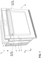
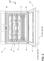
- an oven 10 includes a cabinet 12 and a door 14 attached to the cabinet 12.
- the cabinet 12 defines a cooking chamber 16 and an opening 18 into the cooking chamber 16.
- the door 14 provides selective access to cooking chamber 16.
- the door 14 can be manipulated to, from, and between a closed position 20 ( FIG. 1 ) where access to the cooking chamber 16 from an external environment 22 is denied and an open position 24 ( FIG. 2 ) where access to the cooking chamber 16 from the external environment 22 is allowed.
- the door 14 can be attached to the cabinet 12 via hinges 26.
- the oven 10 includes at least one heating element (not illustrated) to increase the temperature of air within the cooking chamber 16. The temperature of the air can be increased, for example, to subject a food item 28 to a cooking operation.
- the door 14 includes an external surface 30 that faces the external environment 22.
- the door 14 further includes structural components 32a, 32b, 32c, ... 32n that form an interior 34 within the door 14.
- the door 14 includes an aperture 36 that is open within the interior 34 and open at a component 38 of the door 14 providing the external surface 30.
- the aperture 36 can extend through multiple components of the door 14, such as the components 32b, 38.
- the door 14 further includes a mounting stud 40.
- the mounting stud 40 includes a head 42 within the interior 34 of the door 14, a shank 44 extending from the head 42, and a threaded end 46 extending from the shank 44.
- the head 42 has a diameter that is larger than aperture 36 of the structural component 32b of the door 14 through which the mounting stud 40 is located at the interior 34.
- Portions of the aperture 36 closer to the external environment 22 can have a diameter larger than the diameter of the component forming the portion of the aperture 36 open at the interior 34 of the door 14.
- the shank 44 projects forward 48 from the head 42 disposed within the interior 34 through the aperture 36 toward the external environment 22.
- the threaded end 46 can terminate within the aperture 36 or extend beyond the external surface 30 of the door 14.
- the component 38 of the door 14 providing the external surface 30 of the door 14 can be a wrapper made of metal, such as stainless steel.
- the oven 10 further includes a handle assembly 50.
- the handle assembly 50 includes a handle 52.
- the handle assembly 50 includes, and can move to, from, and between, (i) an attached state 54 (see, e.g., FIGS. 5 and 7 ), (ii) a detachable state 56 (see, e.g., FIG. 8 ), and (iii) a detached state 58 (see, e.g., FIG. 9 ).
- the attached state 54 the handle assembly 50 is attached to the door 14 through coupling with the mounting stud 40.
- the detachable state 56 the handle assembly 50 can be removed from the door 14, such as with the application of a force 60 that pulls the handle assembly 50 away from the door 14.
- the handle assembly 50 is no longer coupled to the mounting stud 40 and is not touching the door 14.
- the force 60 successfully pulled the handle assembly 50 away from the door 14 to the detached state 58.
- the handle assembly 50 includes a push-button mechanism 62 (see additionally FIGS. 7-18 ).
- the push-button mechanism 62 when manipulated, transitions the handle assembly 50 from the attached state 54 to the detachable state 56.
- the oven 10 further includes a bushing 64 (see particularly FIGS. 10 and 11 ).
- the bushing 64 includes a door end 66, a handle end 68, and a body portion 70 extending between the door end 66 and the handle end 68.
- the door end 66 extends into the aperture 36 of the door 14.
- the handle end 68 projects away from the aperture 36 and the external surface 30 of the door 14.
- the handle end 68 projects toward the handle 52, when the handle assembly 50 is in the attached state 54 and the detachable state 56.
- the bushing 64 further includes a flange 72 and a recess 74.
- the flange 72 projects radially outward from the body portion 70.
- the recess 74 is disposed adjacent to the flange 72 between the flange 72 and the handle end 68.
- the recess 74 is recessed radially inward into the body portion 70.
- the bushing 64 further includes a receiving cavity 76.
- the receiving cavity 76 is open at the door end 66.
- the mounting stud 40 projects into the receiving cavity 76 (see, e.g., FIGS. 7-9 ) in a fastening manner to fasten the bushing 64 to the door 14.
- one or both of the mounting stud 40 and the receiving cavity 76 can be threaded to facilitate fastening of the bushing 64 to the mounting stud 40.
- the handle assembly 50 further includes a standoff 78 (see, e.g., FIGS. 12-14 ).
- the standoff 78 is disposed between the handle 52 and the external surface 30 of the door 14.
- the standoff 78 includes a top surface 80, a bottom surface 82, a door edge 84, and a handle edge 86.
- the top surface 80 faces upwards 88, when the door 14 is in the closed position 20.
- the bottom surface 82 faces downwards 90, when the door 14 is in the closed position 20.
- the handle edge 86 faces the handle 52.
- the handle edge 86 can contact the handle 52.
- the handle edge 86 can be contoured to match a contour of the handle 52.
- the standoff 78 further includes two lateral sides 92, 94 that face in opposite directions.
- the standoff 78 further includes a bushing receiver 96.
- the bushing receiver 96 is disposed elevationally (from the perspective of when the door 14 is in the closed position 20) between the top surface 80 and the bottom surface 82.
- the bushing receiver 96 is disposed between the two lateral sides 92, 94.
- the bushing receiver 96 is disposed between the handle edge 86 and the door edge 84.
- the bushing receiver 96 is open at the door edge 84.
- the bushing receiver 96 is sized and shaped to receive the bushing 64 attached to the mounting stud 40 when the handle 52 is in the attached state 54.
- the bushing receiver 96 can be slightly smaller than the bushing 64 so that the bushing 64 friction fits within, but is still separable from, the bushing receiver 96.
- the bushing receiver 96 can release from the bushing 64 while the handle 52 is pulled away from the door 14 when the handle assembly 50 is in the detachable state 56 to transition to the detached state 58. Likewise, the bushing receiver 96 can receive the bushing 64 as the handle assembly 50 transitions from the detached state 58 to the detachable state 56 (and ultimately the attached state 54).
- the handle 52 includes (see, e.g., FIGS. 15-16 ) a hollow cylinder 98.
- a hollow cylinder 98 there is a cavity 100 disposed within the handle 52.
- the hollow cylinder 98 includes a first end 102 and a second end 104.
- the hollow cylinder 98 further includes a pair of apertures 106 through the hollow cylinder 98.
- the pair of apertures 106 are disposed closer to the first end 102 of the hollow cylinder 98 than to the second end 104 (e.g., near the first end 102).
- the hollow cylinder 98 further includes a pair of apertures 108 disposed closer to the second end 104 of the hollow cylinder 98 than to the first end 102 (e.g., near the second end 104).
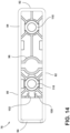
- the standoff 78 further includes a pair of apertures 110.
- the pair of apertures 110 are disposed elevationally (from the perspective of when the door 14 is in the closed position 20) between the top surface 80 and the bottom surface 82.
- the pair of apertures 110 of the standoff 78 are aligned with the pair of apertures 106 of the handle 52.
- a pair of fasteners 112 extend through the pair of apertures 110 of the standoff 78 and then through the pair of apertures 106 of the handle 52 to fasten the standoff 78 and the handle 52 together.
- the push-button mechanism 62 includes a pair of compression springs 114 (see, e.g., FIGS. 7-9 ) and a push-button body 116 (see., e.g., FIGS. 17-18 ).
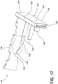
- the push-button body 116 includes a button wall 118.
- the button wall 118 has a top edge 120, a bottom edge 122, a rear edge 124, a forward edge 126, an outside surface 128, and an inside surface 130.
- the top edge 120 faces upwards 88, when the door 14 is in the closed position 20.
- the bottom edge 122 faces downwards 90, when the door 14 is in the closed position 20.
- the rear edge 124 faces the external surface 30 of the door 14.
- the forward edge 126 faces the handle 52.
- the outside surface 128 faces the external environment 22.
- the inside surface 130 faces away from the outside surface 128.
- the push-button body 116 further includes a pair of projections 132 and another projection 134.
- the pair of projections 132 extend from the inside surface 130 of the button wall 118 away from the outside surface 128 of the button wall 118.
- the pair of compression springs 114 are disposed around the pair of projections 132.
- the other projection 134 extends from the inside surface 130 of the button wall 118 away from the outside surface 128 of the button wall 118.
- the push-button body 116 further includes a locking wall 136.
- the locking wall 136 extends from the inside surface 130 of the button wall 118 away from the outside surface 128 of the button wall 118.
- the locking wall 136 and the button wall 118 are substantially orthogonal relative to each other.
- the locking wall 136 includes a locking aperture 138 therethrough.
- the locking aperture 138 has an unlocking portion 140 and a locking portion 142.
- the locking portion 142 is disposed further away from the inside surface 130 of the button wall 118 than the unlocking portion 140.
- the locking portion 142 can be narrower than the unlocking portion 140.
- the standoff 78 houses the push-button mechanism 62 (see FIGS. 7-9 ).
- the push-button body 116 is disposed between the top surface 80 and the bottom surface 82 of the standoff 78.
- the button wall 118 of the push-button body 116 is disposed at the lateral side 94 of the standoff 78.
- the rear edge 124 of the button wall 118 is aligned with the door edge 84 of the standoff 78.
- the forward edge 126 of the button wall 118 is disposed near the handle edge 86 of the standoff 78.
- the locking wall 136 of the push-button body 116 extends laterally near the door edge 84 of the standoff 78 toward the lateral side 92 of the standoff 78.
- the locking aperture 138 through locking wall 136 is aligned with the bushing receiver 96 of the standoff 78.
- the body portion 70 of the bushing 64 extends through the locking aperture 138 of the push-button body 116 and into the bushing receiver 96 of the standoff 78.
- the door end 66 of the bushing 64 resides with the bushing receiver 96 of the standoff 78.
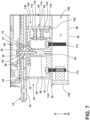
- the push-button body 116 has and can move to, from, and between, a relaxed position 144 (see, e.g., FIG. 7 ) and a pushed position (see, e.g., FIG. 8 ).
- a relaxed position 144 see, e.g., FIG. 7
- a pushed position see, e.g., FIG. 8
- the standoff 78 further includes a spring barrier wall 150 opposing the inside surface 130 of the button wall 118.
- the pair of compression springs 114 are disposed between the spring barrier wall 150 and the inside surface 130 of the button wall 118. The pair of compression springs 114 thus bias the push-button body 116 to the relaxed position 144.
- the bushing 64 extends through the locking aperture 138 of the locking wall 136.
- the locking portion 142 of the locking aperture 138 cooperates with the bushing 64 to secure the handle assembly 50 to the door 14. More specifically, the locking portion 142 of the locking aperture 138 at least partially resides within the recess 74 of the bushing 64.
- the flange 72 of the bushing 64 is disposed between the locking wall 136 and the external surface 30 of the door 14.
- the body portion 70 of the bushing 64 adjacent to the recess 74 in the forward 48 direction towards the handle end 68 opposes the locking wall 136 adjacent to the locking portion 142 of the locking aperture 138.
- the bushing 64 resists the force 60 pulling the handle assembly 50 away from the door 14 to maintain the handle assembly 50 in the attached state 54.
- the push-button body 116 can be manipulated via application of the force 148 into the pushed position 146 (see FIG. 8 ). Moving the push-button body 116 to the pushed position 146 pushes the locking portion 142 of the locking aperture 138 away from residing within the recess 74 of the bushing 64. The bushing 64 still extends through the locking aperture 138. However, the bushing 64 is free from interaction with the locking portion 142 of the locking aperture 138, and does not cooperate with the bushing 64 to keep the handle assembly 50 in the attached state 54. Instead, the unlocking portion 140 of the locking aperture 138 is disposed around the bushing 64 and clear of the bushing 64.
- the pair of projections 132 holding the compression springs 114 extend through a slot 152 through the spring barrier wall 150 of the standoff 78.
- the slot 152 is positioned to allow the pair of projections 132 to extend through the slot 152 but still allow the spring barrier wall 150 to energize the pair of compression springs 114.
- the other projection 134 extending from the button wall 118 cooperates with the spring barrier wall 150 to limit the extent to which the push-button body 116 can be pushed into the standoff 78 as the push-button body 116 is manipulated via the force 148.
- the pair of compression springs 114 (energized while the push-button body 116 is in the pushed position 146) push the push-button body 116 back to the relaxed position 144.
- the handle 52 When the handle assembly 50 is in the detached state 58, the handle 52 can be replaced with a new handle 52 of the user's desire (e.g., having a desired color or finish) by removing the pair of fasteners 112, removing the handle 52 from the standoff 78, adding the new handle 52 to the standoff 78, and then using the pair of fasteners 112 to fasten the new handle 52 to the standoff 78.
- the handle assembly 50 can be then transitioned from the detached state 58 to the attached state 54 by manipulating the push-button body 116 to the pushed position 146 via the force 148, sliding the bushing receiver 96 of the standoff 78 over the bushing 64, and then releasing the push-button body 116.
- the oven 10 includes an anchor cylinder 154 (see, e.g., FIGS. 24-25 ).
- the anchor cylinder 154 couples the handle assembly 50A to the mounting stud 40 of the door 14.
- the anchor cylinder 154 includes a door end 156, a handle end 158, and a body 160 that extends between the door end 156 and the handle end 158.
- the door end 156 has an aperture 162 and receives the mounting stud 40 to couple the handle assembly 50A to the door 14.
- the mounting stud 40 can be threaded to fasten the mounting stud 40 within the aperture 162 of the door end 156 of the anchor cylinder 154.
- the anchor cylinder 154 further includes a radial groove 164.
- the radial groove 164 is disposed near the handle end 158 (e.g., closer to the handle end 158 than to the door end 156).
- the handle assembly 50A further includes a standoff 78A (see, e.g., FIGS. 26-27 ).
- the standoff 78A includes a top surface 166, a bottom surface 168, a door edge 170, and a handle edge 172.
- the top surface 166 faces upwards 88 when the door 14 is in the closed position 20.
- the bottom surface 168 faces downwards 90 when the door 14 is in the closed position 20.
- the top surface 166 and the bottom surface 168 face in generally opposite directions.
- the door edge 170 faces the external surface 30 of the door 14.
- the handle edge 172 faces away from the external surface 30 of the door 14.
- the standoff 78A further includes a pair of lateral sides 174, 176 that face in opposite directions.
- the standoff 78A further includes a pair of apertures 178.
- the pair of apertures 178 are disposed between the top surface 166 and the bottom surface 168, between the pair of lateral sides 174, 176, and are open at both the handle edge 172 and the door edge 170.
- Each of the pair of apertures 178 has a larger diameter section 180.
- the larger diameter sections 180 are open at the door edge 170.
- the standoff 78A further includes an anchor aperture 182.
- the anchor aperture 182 is disposed between the top surface 166 and the bottom surface 168, between the pair of lateral sides 174, 176, and is open at both the handle edge 172 and the door edge 170.
- the anchor aperture 182 is sized to receive the anchor cylinder 154.
- the anchor aperture 182 is disposed laterally between the pair of apertures 178.
- the handle assembly 50A further includes the handle 52A (see, e.g., FIGS. 28-29 ).
- the handle 52A includes a first end 184 and a second end 186.
- the handle 52A further includes a hollow portion 188 forming an interior chamber 190.
- the interior chamber 190 is disposed at the first end 184 of the handle 52A.
- the handle 52A further includes an opening 192 into the interior chamber 190 disposed at the first end 184.
- the handle 52A further includes a recess 194 at the hollow portion 188 that narrows the interior chamber 190.
- the handle 52A further includes a pair of apertures 196 and an anchor aperture 198 disposed between the pair of apertures 196.
- the handle assembly 50A further includes a push-button mechanism 200.
- the push-button mechanism 200 includes a compression spring 202 and a push-button body 204.
- the push-button body 204 includes a button 206 and a hollow semi-cylinder 208 extending from the button 206.
- the hollow semi-cylinder 208 includes a planar wall 210, a semi-cylindrical wall 212 contiguous with the planar wall 210, and an internal chamber 214.
- the planar wall 210 and the semi-cylindrical wall 212 at least partially bound the internal chamber 214.
- the push-button body 204 further includes an anchor aperture 216.
- the anchor aperture 216 is through the planar wall 210.
- the anchor aperture 216 includes a locking section 218 and an unlocking section 220.
- the unlocking section 220 is larger than the locking section 218.
- both the locking section 218 and the unlocking section 220 can have a height 222, 224, respectively.
- the height 222 of the locking section 218 is shorter than the height 224 of the unlocking section 220.
- the button 206 can display a logo that is visible from the external environment 22.
- the push-button mechanism 200 is disposed within the interior chamber 190 of the handle 52A.
- the hollow semi-cylinder 208 of the push-button body 204 is disposed further within the interior chamber 190 than the button 206.
- the hollow semi-cylinder 208 extends inward into the internal chamber 214 from the button 206.
- the button 206 of the push-button body 204 is manipulable at the opening 192 of the handle 52A.
- the button 206 is open to the external environment 22 and accessible at the opening 192.
- the planar wall 210 of the hollow semi-cylinder 208 faces the recess 194 of the handle 52A.
- the compression spring 202 is disposed between the button 206 and the recess 194 of the handle 52A at the first end 184.
- the handle edge 172 of the standoff 78A faces the handle 52A and is disposed within the recess 194 of the handle 52A near the first end 184 of the handle 52A.
- a pair of fasteners 226 extend into the pair of apertures 178 of the standoff 78A, through the pair of apertures 196 of the handle 52A to enter the interior chamber 190 of the handle 52A, and into the anchor aperture 216 of the hollow semi-cylinder 208 of the push-button body 204 to terminate within the internal chamber 214 of the push-button body 204.
- the pair of fasteners 226 thus fasten the handle 52A and the standoff 78A together.
- the pair of fasteners 226 each have a head 228 that is disposed within the larger diameter section 180 of their respective aperture 178 of the standoff 78A.
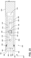
- the handle assembly 50A includes and can be manipulated to, from, and between an attached state 230 (see FIGS. 21 and 22 ) and a detachable state 232 (see FIG. 23 ).
- the handle assembly 50A is attached to the door 14 through coupling with the mounting stud 40 via the anchor cylinder 154.
- the door end 156 of the anchor cylinder 154 is fastened to the mounting stud 40.
- the body 160 of the anchor cylinder 154 projects through the anchor aperture 182 of the standoff 78A, through the anchor aperture 198 of the handle 52A at the first end 184, and then through the anchor aperture 216 of the push-button body 204.
- the handle end 158 of the anchor cylinder 154 terminates within the interior chamber 190 of the handle 52A and more specifically the internal chamber 214 of the push-button body 204.
- the radial groove 164 of the anchor cylinder 154 is positioned to interact with the planar wall 210 of the push-button body 204 at the anchor aperture 216.
- the handle end 158 of the anchor cylinder 154 has a diameter 234 that is larger than the height 222 of the locking section 218 of the anchor aperture 216 of the push-button body 204 but smaller than the height 224 of the unlocking section 220 of the anchor aperture 216.
- the radial groove 164 of the anchor cylinder 154 extends through the locking section 218 of the anchor aperture 216.
- the planar wall 210 adjacent to the locking section 218 is disposed between the handle end 158 of the anchor cylinder 154 and the external surface 30 of the door 14.
- the interaction between the planar wall 210 and the handle end 158 of the anchor cylinder 154 thus secures the handle assembly 50A in the attached state 230 attached to the door 14.
- the standoff 78A is disposed between the handle 52A and the external surface 30 of the door 14.
- the planar wall 210 of the hollow semi-cylinder 208 of the push-button body 204 faces the door 14.
- the push-button body 204 has and can move to, from, and between a relaxed position 236 (see FIGS. 21 and 22 ) and a pushed position 238 (see FIG. 23 ).
- the relaxed position 236 the push-button body 204 is not being manipulated by a force 240 from the external environment 22.
- the button 206 is sized and positioned to be flush with the opening 192 of the handle 52A when the push-button body 204 is in the relaxed position 236.
- the force 240 upon the button 206 manipulates the push-button body 204 further into the internal chamber 214 of the handle 52A.
- the compression spring 202 of the push-button mechanism 200 energizes when the force 240 manipulates the push-button body 204 to the pushed position 238.
- the compression spring 202 thus biases the push-button body 204 back to the relaxed position 236 when the force 240 ceases.
- Manipulating the push-button body 204 to the pushed position 238 transitions the handle assembly 50A from the attached state 230 to the detachable state 232 where the handle assembly 50A can be removed from the door 14 by decoupling from the anchor cylinder 154.
- the radial groove 164 of the anchor cylinder 154 extends through the unlocking section 220 of the anchor aperture 216 of the push-button body 204.
- the planar wall 210 of the push-button body 204 adjacent to the unlocking section 220 and the handle end 158 of the anchor cylinder 154 do not interact.
- the handle assembly 50A is thus in the detachable state 232 and can be withdrawn from the door 14 leaving the anchor cylinder 154 attached to the mounting stud 40.
- the user can then replace the handle 52A if desired. Thereafter, the user can reattach the handle assembly 50A to the door 14 by reversing the above described process.
- FIGS. 32-41 another handle assembly 50B is herein described that can be selectively attached and detached from the mounting stud 40 of the door 14 of the oven 10.
- the handle assembly 50B is utilized with a bushing 242 to couple the handle assembly 50B to the mounting stud 40 of the door 14.
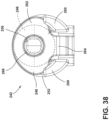
- the bushing 242 (see, e.g., FIGS. 36-38 ) includes a body 244, a snap-fit piece 246 attached to the body 244, and a bushing fastener 248 that fastens the snap-fit piece 246 to the body 244.
- the body 244 includes a door end 250 and a handle end 252.
- the door end 250 includes an aperture 254 that extends toward the handle end 252.
- the aperture 254 receives the mounting stud 40 to fasten the bushing 242 to the door 14.
- the handle end 252 includes an aperture 256 that extends toward the door end 250.
- the bushing 242 further includes a recess 258 into the body 244.
- the recess 258 is disposed into the body 244 between the door end 250 and the handle end 252.
- the bushing 242 further includes a pair of spaced apart fingers 260.
- the pair of spaced apart fingers 260 extend from the handle end 252 and away from the external surface 30 of the door 14.
- the snap-fit piece 246 includes an O-shaped section 262, a flexural element 264, and a retaining feature 266.
- the O-shaped section 262 is disposed against the handle end 252 of the body 244.
- the O-shaped section 262 has a central aperture 268.
- the central aperture 268 is aligned with the aperture 256 of the handle end 252 to receive the bushing fastener 248.
- a bushing fastener 248 extends through both the central aperture 268 of the snap-fit piece 246 and the aperture 256 of the body 244 to fasten the snap-fit piece 246 to the body 244.
- the flexural element 264 extends from the O-shaped section 262 between the spaced apart fingers 260 of the body 244 and then substantially orthogonally relative to the O-shaped section 262 to terminate within or adjacent to the recess 258 that is in the body 244.
- the flexural element 264 terminates in the retaining feature 266.
- the handle assembly 50B includes a standoff 78B (see, e.g., FIGS. 40-41 ).
- the standoff 78B includes a top surface 270 and a bottom surface 272.
- the top surface 270 faces upwards 88 when the door 14 is in the closed position 20.
- the bottom surface 272 faces downwards 90 when the door 14 is in the closed position 20.
- the standoff 78B further includes a door edge 274, and a handle edge 276.
- the standoff 78B further includes two lateral sides 278, 280 that face in opposite directions.
- the standoff 78B further includes a bushing receiver 282.
- the bushing receiver 282 is disposed between the top surface 270 and the bottom surface 272, and between the two lateral sides 278, 280.
- the bushing receiver 282 is open at the door edge 274 and extends toward the handle edge 276.
- the standoff 78B further includes a pair of fastener apertures 284.
- the pair of fastener apertures 284 are disposed between the top surface 270 and the bottom surface 272, and between the two lateral sides 278, 280.
- the fastener apertures 284 are open at the handle edge 276.
- the standoff 78B further includes an aperture 286 into the bushing receiver 282.
- the aperture 286 is accessible from the external environment 22.
- the aperture 286 of the illustrated embodiment is disposed through the bottom surface 272 of standoff 78B and opens into the bushing receiver 282.
- the standoff 78B further includes a retaining feature 288.
- the retaining feature 288 is disposed within the bushing receiver 282.
- the retaining feature 288 includes a sloped portion 290 and a vertical portion 292.
- the vertical portion 292 is disposed adjacent to the aperture 286.
- the handle assembly 50B includes a handle 52B.
- the handle 52B includes a hollow cylinder 296, a first end 298, and a second end 300.
- the handle 52B further includes a pair of apertures 302 through the hollow cylinder 296.
- the pair of apertures 302 are disposed near the first end 298 of the handle 52B (e.g., closer to the first end 298 than to the second end 300).
- Each of the pair of apertures 302 of the handle 52B is aligned with a different one of the pair of fastener apertures 284 of the standoff 78B.
- the handle assembly 50B further includes a pair of fasteners 304.
- the pair of fasteners 304 extend through the pair of fastener apertures 284 of the standoff 78B and through the pair of apertures 302 of the handle 52B to fasten the standoff 78B and the handle 52B together.
- the handle edge 276 of the standoff 78B faces the handle 52B.
- the handle assembly 50B includes, and can move to, from, and between an attached state 306 (see, e.g., FIG. 34 ) and a detachable state 308 (see, e.g., FIG. 35 ).
- the handle assembly 50B is attached to the door 14 through coupling with the mounting stud 40.
- the body 244 of the bushing 242 is at least partially disposed within the bushing receiver 282 of the standoff 78B.
- the handle end 252 of the body 244 of the bushing 242 is disposed within the bushing receiver 282 while the door end 250 of the body 244 may not be.
- the retaining feature 288 of the standoff 78B cooperates with the retaining feature 266 of the snap-fit piece 246 of the bushing 242 to couple the handle assembly 50B to the bushing 242 and place the handle assembly 50B in the attached state 306. More specifically, the retaining feature 266 of the snap-fit piece 246 of the bushing 242 faces the vertical portion 292 of the retaining feature 288 of the standoff 78B when the handle assembly 50B is in the attached state 306 and thus resists the force 60 pulling the handle 52B away from the external surface 30 of the door 14.
- the standoff 78B is disposed between the external surface 30 of the door 14 and the handle 52B.
- the door edge 274 of the standoff 78B faces the door 14.
- the retaining feature 266 of the snap-fit piece 246 of the bushing 242 is manipulated (see FIG. 35 ).
- the retaining feature 266 is manipulated from the external environment 22 through the aperture 286 through the standoff 78B. For example, a force 310 upon the retaining feature 266 of the snap-fit piece 246 causes the flexural element 264 to flex and the retaining feature 266 moves further into the recess 258 of the body 244 of the bushing 242.
- the retaining feature 266 of the snap-fit piece 246 no longer opposes the vertical portion 292 of the retaining feature 288 of the standoff 78B and thus is decoupled therefrom.
- the force 60 pulling the handle 52B away from the door 14 can thus remove the handle assembly 50B.
- the bushing 242 remains attached to the mounting stud 40 of the door 14 while the bushing 242 slides out of the bushing receiver 282 of the standoff 78B of the handle assembly 50B. The user can then replace the handle 52B as desired.
- the user places the bushing 242 within the bushing receiver 282 and moves the handle assembly 50B closer to the external surface 30 of the door 14.
- the sloped potion 290 of the retaining feature 288 of the standoff 78B causes the flexural element 264 to flex and the retaining feature 266 of the snap-fit piece 246 moves further into the recess 258 of the body 244 of the bushing 242.
- the retaining feature 266 of the snap-fit piece 246 clears the retaining feature 288 of the standoff 78B, and the flexural element 264 causes the retaining feature 288 to snap into position opposing the vertical portion 292 of the retaining feature 288 of the standoff 78B.
- the handle assembly 50B is thus again in the attached state 306.
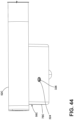
- FIGS. 42-44 another handle assembly 50C is herein described that can be selectively attached and detached from the mounting stud 40 of the door 14 of the oven 10.
- the handle assembly 50C can be manipulated to, from, and between an attached state 312 (see, e.g., FIG. 43 ) attached to the door 14 and a detachable state (not separately illustrated) separable from the door 14.
- the door 14 includes a first bushing 314 attached to the mounting stud 40 of the door 14.
- the first bushing 314 extends outside of the interior 34 of the door 14.
- the door 14 further includes a second bushing 316 attached to the first bushing 314 such as through the use of cooperating threads. Degree of separation of the second bushing 316 from the external surface 30 of the door 14 can be adjusted by tightening or loosening the second bushing 316 relative to the first bushing 314.
- the second bushing 316 has a radial recess 318.
- the handle assembly 50C includes a handle 52C and a standoff 78C.
- a pair of fasteners 320 fasten the handle 52C and the standoff 78C together.
- the standoff 78C is disposed between the handle 52C and the door 14.
- the standoff 78C further includes a bushing receiver 322. In the attached state 312, the second bushing 316 and a portion of the first bushing 314 are disposed within the bushing receiver 322.
- the standoff 78C further includes an aperture 324 that is open to the external environment 22 and a grub screw 326 sized to be screwed into and out of the aperture 324.
- the aperture 324 is positioned so that the grub screw 326, when inserted into the aperture 324, is disposed within the radial recess 318 of the second bushing 316.
- the grub screw 326 thus attaches the handle assembly 50C to the second bushing 316, and thus the door 14, and places the handle assembly 50C in the attached state 312.
- the user can remove the grub screw 326.
- the user can then pull the handle assembly 50C away from the door 14 and the first bushing 314 and the second bushing 316 remain attached to the door 14 and withdraw from the bushing receiver 322 of the standoff 78C.
- the user can then replace the handle 52C.
- the user can reverse the above process to reattach the handle assembly 50C.
- the first bushing 314 and the second bushing 316 could be combined into a single bushing with the radial recess 318 and the bushing still receiving the mounting stud 40.
- the door 14 for each of the handle assemblies 50-50C discussed above can be the same without having to recite the features of the door 14 for every one of the handle assemblies 50-50C.
- the door 14 can include two identical handle assemblies 50-50C to attach the respective handle 52-52C to the door 14.
- the discussion above can be thought of as the left side handle assembly 50-50C dividing the oven 10 into two approximately equal halves.
- the oven 10 can then further include a right side handle assembly sharing the same handle as the left hand handle assembly 50-50C.
- the right side handle assembly can be a mirror image of the left side handle assembly 50-50C or identical to the left side handle assembly 50-50C but sharing the handle in common.
- All of the handle assemblies 50-50C address the problem described above, because the user can cause the handle assembly 50-50C to move from the attached state 54, 230, 306, 312 to the detachable state 56, 232, 308, from the external environment 22. While in the detachable state 56, 232, 308, the user can then separate the handle assembly 50-50C from the door 14 and replace the handle 52-52C. The user does not need to remove the door 14 from the cabinet 12 of the oven 10 in order to remove the handle assembly 50-50C. The process of changing the handle 52-52C is thus much easier for the user to perform.
- the user can make the standoff 78-78C of the handle assembly 50-50C flush with the external surface 30 of the door 14.
- the bushings 64, 242, 314/316 can be adjusted so that there is no unreasonably large gap between the standoff 78-78C and the external surface 30 of the door 14.
- the handle assemblies 50-50C can be manipulated to their respective detachable states 56, 232, 308 without the use of a tool. In the instances of the handle assemblies 50, 50A, and 50C, a screwdriver is likely to be the only tool required.
- handle assembly 50B with the snap-fit piece 246, reattaching the handle assembly 50B to the door 14 to take the attached state 306 would not require a tool either.
- the handle assemblies 50-50C allow for handles 52-52C to be sold separately in a variety of colors and finishes to accommodate the user's aesthetic desire.
- the handle assemblies 50-50C can be utilized with any appliance that incorporates a door with a handle, such as a refrigerator, a dishwasher, an oven, a microwave oven, and so on.
- an oven comprises: (a) a door comprising (i) an external surface that faces an external environment and (ii) a mounting stud that projects from an interior of the door toward the external environment; and (b) a handle assembly comprising a handle, an attached state where the handle assembly is attached to the door through coupling with the mounting stud, a detachable state where the handle can be removed from the handle assembly, and a push-button mechanism or a snap-fit feature that, when manipulated, transitions the handle assembly from the attached state to the detachable state.
- the oven of the first aspect further comprises a bushing comprising: (a) a door end that extends into an aperture into the door, (b) a handle end that projects away from the external surface of the door, (c) a body portion between the door end and the hand end, (d) a recess adjacent to a flange between the flange and the handle end, and (e) a receiving cavity open at the door end into which the mounting stud projects in a fastening manner to fasten the bushing to the door, and wherein (i) in the attached state, the handle assembly is coupled to the bushing, and (ii) in the detachable state, the handle assembly can be decoupled from the bushing.
- a bushing comprising: (a) a door end that extends into an aperture into the door, (b) a handle end that projects away from the external surface of the door, (c) a body portion between the door end and the hand end, (d) a recess adjacent to a flange between the f
- the oven of the first aspect wherein the handle assembly further comprises a standoff disposed between the handle and the external surface of the door, the standoff housing the push-button mechanism and comprising: (a) a top surface facing upwards when the door is in a closed position, (b) a bottom surface facing downwards when the door is in the closed position, (c) a door edge facing the external surface of the door, (d) a handle edge facing the handle, (e) a pair of apertures disposed elevationally between the top surface and the bottom surface through which a pair of fasteners extend to fasten the standoff and the handle together, and (f) a bushing receiver disposed elevationally between the top surface and the bottom surface, the bushing receiver disposed so that the bushing receiver receives a bushing attached to the mounting stud of the door when the handle is in the attached state but can release from the bushing while the handle is pulled away from the door when the handle assembly is in the detachable state.
- a standoff disposed between the handle and the external surface of the
- the oven of the first aspect is presented, wherein (a) the handle assembly further comprises a standoff disposed between the handle and the external surface of the door, the standoff housing the push-button mechanism, (b) the push-button mechanism comprises a pair of compression springs and a push-button body, (c) the push-button body comprises (i) a relaxed position where the push-button mechanism is not being manipulated by a force external to the oven, (ii) a pushed position where the first push-button mechanism is being manipulated, (iii) a button wall comprising a top edge facing upward when the door is in a closed position, a bottom edge facing downward when the door is in the closed position, a rear edge facing the external surface of the door, a forward edge facing the handle, an outside surface facing the external environment, and an inside surface facing away from the outside surface, (iv) a pair of projections extending from the inside surface of the button wall away from the outside surface of the button wall,
- the oven of the first aspect is presented, wherein (i) the handle assembly further comprises a standoff disposed between the handle and the external surface of the door, (ii) the handle comprises a hollow cylinder with a cavity disposed therein and a pair of apertures through the hollow cylinder, and (iii) a pair of fasteners extend through the pair of apertures to fasten the standoff and the handle together.
- the oven of the first aspect further comprises a bushing fastened to the mounting stud, the bushing partially extending through an aperture of the door into the door and partially extending away from the external surface of the door, the bushing comprising (a) a body portion, (b) a flange projecting radially outward from the body portion, and (c) a recess into the body portion adjacent to the flange, wherein (i) the push-button mechanism comprises a push-button body with a locking wall and a locking aperture through the locking wall, the body portion of the bushing extending through the locking aperture, (ii) the push-button body comprises a relaxed position, and in the relaxed position, the locking wall at least partially resides within the recess of the bushing with the flange of the bushing disposed between the locking wall and the external surface of the door, thus placing the handle assembly in the attached state, and (iii) the push-button body further comprises a pushed position, and in the
- the oven of the sixth aspect is presented, wherein (i) the handle assembly further comprises a standoff disposed between the handle and the external surface of the door, the standoff housing the first push-button mechanism, and (ii) the push-button mechanism further comprises compression springs that cooperate with the standoff to bias the push-button body to the relaxed position.
- the oven of the first aspect is presented or an oven comprising: (a) a door comprising (i) an external surface that faces an external environment and (ii) a mounting stud that projects toward the external environment from an interior of the door; and (b) a handle assembly comprising a handle, an attached state where the handle assembly is attached to the door through coupling with the mounting stud, a detachable state where the handle assembly can be removed from the door, and a push-button mechanism manipulable from an end of the handle that, when manipulated, transitions the handle assembly from the attached state to the detachable state.
- the oven of the eighth aspect further comprises an anchor cylinder coupling the handle assembly to the mounting stud, the anchor cylinder comprising (i) a door end having an aperture that receives the mounting stud to couple the handle assembly to the door, (ii) a handle end that terminates within an interior chamber of the handle, and (iii) a body that extends between the door end and the handle end, with the body projecting through an anchor aperture of the handle to enter the interior chamber of the handle.
- the oven of the eighth aspect is presented, wherein (a) the handle assembly further comprises a standoff disposed between the handle and the external surface of the door, the standoff comprising: (i) a top surface facing upwards when the door is in a closed position, (ii) a bottom surface facing downwards when the door is in the closed position, (iii) a door edge facing the external surface of the door, (iv) a handle edge facing the handle, (v) a pair of apertures disposed between the top surface and the bottom surface through which a pair of fasteners extend to fasten the standoff and the handle together, each of pair of apertures having a larger diameter section open at the door edge where a head of the fastener is disposed, and (vi) an anchor aperture disposed between the top surface and the bottom surface and laterally between the pair of apertures, the anchor aperture open at the door edge and extending through the standoff to open at the handle edge, and (b) the anchor aperture extends through the anchor
- the oven of any one of the eighth through tenth aspects is presented, wherein (i) the handle comprises an interior chamber disposed at the end of the handle and opening into the interior chamber disposed at the end of the handle, and (ii) the push-button mechanism is disposed within the interior chamber of the handle and manipulable at the opening of the handle.
- the oven of the eleventh aspect is presented, wherein (a) the push-button mechanism comprises a compression spring and a push-button body, the push-button body comprises (i) a relaxed position where the push-button body is not being manipulated by a force from the external environment, (ii) a pushed position where the push-button body is being manipulated further into an internal chamber of the handle, (iii) a button accessible at the opening of the handle and sized and positioned to be flush with the opening when the push-button body is in the relaxed position, (iv) a hollow semi-cylinder extending inward into the internal chamber of the handle from the button, the hollow semi-cylinder including a planar wall facing the door, a semi-cylindrical wall contiguous with the planar wall, and an internal chamber bound by the planar wall and the semi-cylindrical wall, and (v) an anchor aperture through the planar wall, the anchor aperture including a locking section and
- the oven of the twelfth aspect further comprises: an anchor cylinder comprising (i) a door end with an aperture into which the mounting stud extends to fasten the anchor cylinder to the mounting stud, (ii) a handle end that terminates within the interior chamber of the push-button body, (iii) a body that extends between the door end and the handle end, with the body projecting through an anchor aperture of the handle to enter the interior chamber of the handle and the anchor aperture of the push-button body to enter the interior chamber of the push-button body, and (iv) a radial groove disposed near the handle end and positioned to interact with the planar wall of the push-button body at the anchor aperture, wherein, the handle end of the anchor cylinder disposed within the interior chamber of the push-button body has a diameter that is larger than a width of the locking section of the anchor aperture of the push-button body but smaller than a width of the unlocking section of the anchor aperture.
- the oven of the thirteenth aspect is presented, wherein (i) in the relaxed position of the push-button body, the radial groove of the anchor cylinder extends through the locking section of the anchor aperture of the push-button body, and the planar wall of the push-button body is disposed between the handle end of the anchor cylinder and the external surface of the door, thus securing the handle assembly in the attached state, and (ii) in the pushed position of push-button body, the radial groove of the anchor cylinder extends through the unlocking section of the anchor aperture of the push-button body, and the planar wall of the push-button body and the anchor cylinder do not interact, thus placing the handle assembly in the detachable state.
- the oven of the first aspect is presented or an oven comprising: (a) a door comprising (i) an external surface that faces an external environment and (ii) a mounting stud that projects from an interior of the door toward the external environment; and (b) a handle assembly comprising a handle, an attached state where the handle assembly is attached to the door through coupling with the mounting stud, a detachable state where the handle can be removed from the handle assembly, and a snap-fit feature accessible to manipulate at the handle assembly that, when manipulated, transitions the handle assembly from the attached state to the detachable state.
- the oven of the fifteenth aspect further comprises a bushing comprising: (a) a body comprising (i) a door end with an aperture to receive and fasten to the mounting stud, (ii) a handle end with an aperture to receive a bushing fastener, the aperture extending toward the door end while the aperture of the door end extends toward the handle end, (iii) a recess into the body disposed between the door end and the handle end, and (iv) a pair of spaced apart fingers extends from the handle end and away from the external surface of the door, (b) a snap-fit piece attached to the body, the snap-fit piece comprising (i) an O-shaped section disposed against the handle end of the body, the O-shaped section having a central aperture aligned with the aperture of the handle end to receive the bushing fastener, (ii) a flexural element extending from the O-shaped section between the pair of spaced apart fingers of the body and then substantially orthogon
- the oven of the fifteenth aspect further comprises a bushing attached to the mounting stud, the bushing comprising a retaining feature;
- the handle assembly further comprises: (a) a standoff disposed between the external surface of the door and the handle, the standoff comprises: (i) a top surface facing upwards when the door is in a closed position, (ii) a bottom surface facing downwards when the door is in the closed position, (iii) a door edge facing the door, (iv) a handle edge facing the handle, (v) a bushing receiver disposed between the top surface and the bottom surface, the bushing receiver open at the door edge and receiving the bushing, (vi) a pair of fastener apertures disposed between the top surface and the bottom surface, the pair of fastener apertures being open at the handle edge, and (vii) an aperture into bushing receiver that is accessible from the external environment, the aperture cooperating with the retaining feature of the bushing to couple the handle assembly to the bushing and thus
- the oven of the fifteenth aspect is presented, wherein (i) the handle comprises a hollow cylinder, a first end, a second end, and a pair of apertures through the hollow cylinder near the first end, and (ii) the handle assembly further comprises a pair of fasteners that extend through the pair of apertures of the handle to fasten the handle to a standoff of the handle assembly.
- the oven of the fifteenth aspect further comprises: a bushing attached to the mounting stud, the bushing comprising a recess, a retaining feature disposed within or adjacent to the recess, the retaining feature attached to a flexural element, wherein (i) the handle assembly further comprises a standoff to which the handle is attached, the standoff comprising a bushing receiver within which the bushing is disposed, a retaining feature that cooperates with the retaining feature of the bushing to couple the handle assembly to the bushing and place the handle assembly in the attached state, and an aperture adjacent the retaining feature that is accessible from an external environment, and (ii) manipulating the retaining feature from the external environment through the aperture causes the flexural element of the bushing to flex and the retaining feature to decouple from the aperture of the handle assembly to place the handle assembly in the detachable state.
- the oven of the nineteenth aspect is presented, wherein the aperture from where the retaining feature of the bushing can be manipulated is disposed at a bottom surface of the standoff.
- the term "coupled” in all of its forms, couple, coupling, coupled, etc. generally means the joining of two components (electrical or mechanical) directly or indirectly to one another. Such joining may be stationary in nature or movable in nature. Such joining may be achieved with the two components (electrical or mechanical) and any additional intermediate members being integrally formed as a single unitary body with one another or with the two components. Such joining may be permanent in nature or may be removable or releasable in nature unless otherwise stated.
- elements shown as integrally formed may be constructed of multiple parts or elements shown as multiple parts may be integrally formed, the operation of the interfaces may be reversed or otherwise varied, the length or width of the structures and/or members or connector or other elements of the system may be varied, the nature or number of adjustment positions provided between the elements may be varied.
- the elements and/or assemblies of the system may be constructed from any of a wide variety of materials that provide sufficient strength or durability, in any of a wide variety of colors, textures, and combinations. Accordingly, all such modifications are intended to be included within the scope of the present innovations. Other substitutions, modifications, changes, and omissions may be made in the design, operating conditions, and arrangement of the desired and other exemplary embodiments without departing from the spirit of the present innovations.
Landscapes
- Engineering & Computer Science (AREA)
- Chemical & Material Sciences (AREA)
- Combustion & Propulsion (AREA)
- Mechanical Engineering (AREA)
- General Engineering & Computer Science (AREA)
- Physics & Mathematics (AREA)
- Thermal Sciences (AREA)
- Electric Ovens (AREA)
Abstract
Description
- The present disclosure generally relates to handle assemblies for an oven, and more specifically, to handle assemblies for a door of an oven that is detachable from an external environment.
- An oven sometimes includes a door and a handle attached to the door. The handle allows a user to more easily open and close the door compared to if the door lacked a handle. The user may, at some point, desire to replace the handle.
- However, there is a problem in that the user cannot replace the handle from the exterior of the oven. Rather, the user typically first has to remove the door from a cabinet of the oven, and then second remove set screws at an inside portion of the door to release the handle from the door. The user may find that to be a difficult process.
- The present disclosure addresses that problem with several handle assemblies that can be manipulated from an attached state to a detachable state where the handle assembly is separable from the oven from the external environment.
- According to one aspect of the present disclosure, an oven comprises: (a) a door comprising (i) an external surface that faces an external environment and (ii) a mounting stud that projects from an interior of the door toward the external environment; and (b) a handle assembly comprising a handle, an attached state where the handle assembly is attached to the door through coupling with the mounting stud, a detachable state where the handle assembly can be removed from the door, and a push-button mechanism that, when manipulated, transitions the handle assembly from the attached state to the detachable state.
- According to another aspect of the present disclosure, an oven comprises: (a) a door comprising (i) an external surface that faces an external environment and (ii) a mounting stud that projects toward the external environment from an interior of the door; and (b) a handle assembly comprising a handle, an attached state where the handle assembly is attached to the door through coupling with the mounting stud, a detachable state where the handle assembly can be removed from the door, and a push-button mechanism manipulable from an end of the handle that, when manipulated, transitions the handle assembly from the attached state to the detachable state.
- According to yet another aspect of the present disclosure, an oven comprises: (a) a door comprising (i) an external surface that faces an external environment and (ii) a mounting stud that projects from an interior of the door toward the external environment; and (b) a handle assembly comprising a handle, an attached state where the handle assembly is attached to the door through coupling with the mounting stud, a detachable state where the handle can be removed from the handle assembly, and a snap-fit feature accessible to manipulate at the handle assembly that, when manipulated, transitions the handle assembly from the attached state to the detachable state.
- These and other features, advantages, and objects of the present disclosure will be further understood and appreciated by those skilled in the art by reference to the following specification, claims, and appended drawings.
- In the drawings:
-
FIG. 1 is a perspective view of an oven, illustrating a door and a handle assembly attached to the door; -
FIG. 2 is an elevation view of the oven ofFIG. 1 , illustrating the door in an open position; -
FIG. 3 is an elevation view of the door ofFIG. 1 with an embodiment of a handle assembly of the present disclosure; -
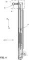
FIG. 4 is an elevation view of a cross-section of the door ofFIG. 3 taken through line IV-IV ofFIG. 3 ; -
FIG. 5 is a magnified view of area V ofFIG. 4 , illustrating the handle assembly attached to the door via a mounting stud; -
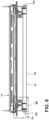
FIG. 6 is an overhead view of a cross-section of the door ofFIG. 3 taken through line VI-VI ofFIG. 3 ; -
FIG. 7 is a magnified view of area VII ofFIG. 6 , illustrating the handle assembly in an attached state attached to the door and the handle assembly including a push-button mechanism in a relaxed state; -
FIG. 8 is the same view asFIG. 7 but this time illustrating the handle assembly in a detachable state, where the handle assembly is separable from the door, as a result of the push-button mechanism being manipulated to a pushed position; -
FIG. 9 is the same view asFIG. 7 but this time illustrating the handle assembly in a detached state separated from the door; -
FIG. 10 is an elevation view of a bushing of the handle assembly ofFIG. 3 , illustrating the bushing having a flange and a recess next to the flange; -
FIG. 11 is a perspective view of the bushing ofFIG. 10 , illustrating a door end of the bushing having a receiving cavity; -
FIG. 12 is a perspective view of a standoff of the handle assembly ofFIG. 3 , illustrating the standoff having a bushing receiver; -
FIG. 13 is a perspective view of the standoff ofFIG. 12 , illustrating the standoff further including a spring barrier wall and a slot through the spring barrier wall; -
FIG. 14 is an elevation view of the standoff ofFIG. 12 , illustrating the standoff further including apertures for fasteners; -
FIG. 15 is an elevation view of a handle of the handle assembly ofFIG. 3 , illustrating the handle including a hollow cylinder; -
FIG. 16 is an overhead view of a cross-section of the handle ofFIG. 15 taken through line XVI-XVI ofFIG. 15 , illustrating the handle including a pair of apertures disposed at a first end of the handle; -
FIG. 17 is a perspective view of a push-button body of the handle assembly ofFIG. 3 , illustrating a button wall and a locking wall extending orthogonally to the button wall; -
FIG. 18 is an elevation view of the push-button body ofFIG. 17 , illustrating a locking aperture through the locking wall; -
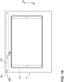
FIG. 19 is an elevation view of the door ofFIG. 1 with another embodiment of a handle assembly of the present disclosure; -
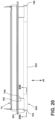
FIG. 20 is an overhead view of the door ofFIG. 19 ; -
FIG. 21 is an overhead view of a cross-section of the door ofFIG. 19 taken through line XXI-XXI ofFIG. 19 , illustrating the handle assembly in an attached state attached to the mounting stud of the door via an anchor cylinder; -
FIG. 22 is an elevation view of a cross-section of the door ofFIG. 19 taken through line XXII-XXII ofFIG. 20 , illustrating the anchor cylinder cooperating with a locking section of an anchor aperture of a push-button body of a push-button mechanism of the handle assembly to place the handle assembly in the attached state attached to the door; -
FIG. 23 is the same view asFIG. 22 , but this time showing the push-button body in a pushed position where an unlocking section of the anchor aperture of the push-button body does not cooperate with the anchor aperture thus placing the handle assembly in a detachable state; -
FIG. 24 is a perspective view of the anchor cylinder, illustrating the anchor cylinder including a radial groove at a handle end; -
FIG. 25 is a perspective view of the anchor cylinder, illustrating a door end including an aperture to receive the mounting stud of the door; -
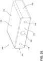
FIG. 26 is a perspective view of a standoff of the handle assembly ofFIG. 19 , illustrating an anchor aperture through which the anchor cylinder extends when the handle assembly is in the attached state; -
FIG. 27 is an elevation view of the standoff; -
FIG. 28 is a perspective view of a handle of the handle assembly ofFIG. 19 , illustrating an interior chamber at a first end of the handle; -
FIG. 29 is a perspective view of the first end of the handle, illustrating a recess and an anchor aperture at the recess; -
FIG. 30 is a perspective view of the push-button body of the handle assembly ofFIG. 19 ; -
FIG. 31 is a perspective view of the push-button body of the handle assembly ofFIG. 19 ; -
FIG. 32 is an elevation view of the door ofFIG. 1 with another embodiment of a handle assembly of the present disclosure; -
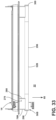
FIG. 33 is an overhead view of the door with the handle assembly ofFIG. 32 ; -
FIG. 34 is an elevation view of a cross-section taken through line XXXIV-XXXIV ofFIG. 33 , illustrating the handle assembly in an attached state attached to the door through the mounting stud of the door; -
FIG. 35 is the same view asFIG. 34 but this time showing the handle assembly being manipulated to a detachable state; -
FIG. 36 is a perspective view of a bushing of the handle assembly ofFIG. 32 , illustrating the bushing including a snap-fit piece; -
FIG. 37 is a bottom view of the bushing, illustrating the snap-fit piece including a flexural element extending through two spaced apart fingers of a body of the bushing; -
FIG. 38 is an elevation view of the bushing; -
FIG. 39 is an overhead view of a cross-section taken through line XXXIX-XXXIX ofFIG. 32 ; -
FIG. 40 is a perspective view of a standoff of the handle assembly ofFIG. 32 , illustrating a bushing receiver; -
FIG. 41 is a perspective view of a cross-section of the standoff taken through line XLI-XLI ofFIG. 40 ; -
FIG. 42 is an elevation view of the door ofFIG. 1 with another embodiment of a handle assembly of the present disclosure; -
FIG. 43 is an overhead view of a cross-section taken through line XLIII-XLIII ofFIG. 42 ; and -
FIG. 44 is a perspective view of the handle assembly ofFIG. 42 . - The components in the figures are not necessarily to scale, emphasis instead being placed upon illustrating the principles described herein.
- The present illustrated embodiments reside primarily in combinations of method steps and apparatus components related to handle assemblies of an oven. Accordingly, the apparatus components and method steps have been represented, where appropriate, by conventional symbols in the drawings, showing only those specific details that are pertinent to understanding the embodiments of the present disclosure so as not to obscure the disclosure with details that will be readily apparent to those of ordinary skill in the art having the benefit of the description herein. Further, like numerals in the description and drawings represent like elements.
- For purposes of description herein, the terms "upper," "lower," "right," "left," "rear," "front," "vertical," "horizontal," and derivatives thereof shall relate to the disclosure as oriented in
FIG. 1 . Unless stated otherwise, the term "front" shall refer to the surface of the element closer to an intended viewer, and the term "rear" shall refer to the surface of the element further from the intended viewer. However, it is to be understood that the disclosure may assume various alternative orientations, except where expressly specified to the contrary. It is also to be understood that the specific devices and processes illustrated in the attached drawings, and described in the following specification are simply exemplary embodiments of the inventive concepts defined in the appended claims. Hence, specific dimensions and other physical characteristics relating to the embodiments disclosed herein are not to be considered as limiting, unless the claims expressly state otherwise. - The terms "including," "comprises," "comprising," or any other variation thereof, are intended to cover a non-exclusive inclusion, such that a process, method, article, or apparatus that comprises a list of elements does not include only those elements but may include other elements not expressly listed or inherent to such process, method, article, or apparatus. An element preceded by "comprises a ... " does not, without more constraints, preclude the existence of additional identical elements in the process, method, article, or apparatus that comprises the element.
- Referring to
FIGS. 1 and2 , anoven 10 includes acabinet 12 and adoor 14 attached to thecabinet 12. Thecabinet 12 defines acooking chamber 16 and anopening 18 into thecooking chamber 16. Thedoor 14 provides selective access to cookingchamber 16. Thedoor 14 can be manipulated to, from, and between a closed position 20 (FIG. 1 ) where access to thecooking chamber 16 from anexternal environment 22 is denied and an open position 24 (FIG. 2 ) where access to thecooking chamber 16 from theexternal environment 22 is allowed. Thedoor 14 can be attached to thecabinet 12 via hinges 26. Theoven 10 includes at least one heating element (not illustrated) to increase the temperature of air within thecooking chamber 16. The temperature of the air can be increased, for example, to subject afood item 28 to a cooking operation. Thedoor 14 includes anexternal surface 30 that faces theexternal environment 22. - Referring now to
FIGS. 3-5 , thedoor 14 further includesstructural components door 14. Thedoor 14 includes anaperture 36 that is open within the interior 34 and open at acomponent 38 of thedoor 14 providing theexternal surface 30. Theaperture 36 can extend through multiple components of thedoor 14, such as thecomponents door 14 further includes a mountingstud 40. The mountingstud 40 includes ahead 42 within theinterior 34 of thedoor 14, ashank 44 extending from thehead 42, and a threadedend 46 extending from theshank 44. Thehead 42 has a diameter that is larger thanaperture 36 of thestructural component 32b of thedoor 14 through which the mountingstud 40 is located at the interior 34. Portions of theaperture 36 closer to theexternal environment 22 can have a diameter larger than the diameter of the component forming the portion of theaperture 36 open at the interior 34 of thedoor 14. Theshank 44 projects forward 48 from thehead 42 disposed within the interior 34 through theaperture 36 toward theexternal environment 22. The threadedend 46 can terminate within theaperture 36 or extend beyond theexternal surface 30 of thedoor 14. Thecomponent 38 of thedoor 14 providing theexternal surface 30 of thedoor 14 can be a wrapper made of metal, such as stainless steel. - The
oven 10 further includes ahandle assembly 50. Thehandle assembly 50 includes ahandle 52. Thehandle assembly 50 includes, and can move to, from, and between, (i) an attached state 54 (see, e.g.,FIGS. 5 and7 ), (ii) a detachable state 56 (see, e.g.,FIG. 8 ), and (iii) a detached state 58 (see, e.g.,FIG. 9 ). In the attachedstate 54, thehandle assembly 50 is attached to thedoor 14 through coupling with the mountingstud 40. In thedetachable state 56, thehandle assembly 50 can be removed from thedoor 14, such as with the application of aforce 60 that pulls thehandle assembly 50 away from thedoor 14. Finally, in thedetached state 58, thehandle assembly 50 is no longer coupled to the mountingstud 40 and is not touching thedoor 14. For example, while initially in thedetachable state 56, theforce 60 successfully pulled thehandle assembly 50 away from thedoor 14 to thedetached state 58. - In embodiments, the
handle assembly 50 includes a push-button mechanism 62 (see additionallyFIGS. 7-18 ). The push-button mechanism 62, when manipulated, transitions thehandle assembly 50 from the attachedstate 54 to thedetachable state 56. For example, in embodiments, theoven 10 further includes a bushing 64 (see particularlyFIGS. 10 and11 ). Thebushing 64 includes adoor end 66, ahandle end 68, and abody portion 70 extending between thedoor end 66 and thehandle end 68. Thedoor end 66 extends into theaperture 36 of thedoor 14. Thehandle end 68 projects away from theaperture 36 and theexternal surface 30 of thedoor 14. Thehandle end 68 projects toward thehandle 52, when thehandle assembly 50 is in the attachedstate 54 and thedetachable state 56. - The
bushing 64 further includes aflange 72 and arecess 74. Theflange 72 projects radially outward from thebody portion 70. Therecess 74 is disposed adjacent to theflange 72 between theflange 72 and thehandle end 68. Therecess 74 is recessed radially inward into thebody portion 70. Thebushing 64 further includes a receivingcavity 76. The receivingcavity 76 is open at thedoor end 66. The mountingstud 40 projects into the receiving cavity 76 (see, e.g.,FIGS. 7-9 ) in a fastening manner to fasten thebushing 64 to thedoor 14. For example, one or both of the mountingstud 40 and the receivingcavity 76 can be threaded to facilitate fastening of thebushing 64 to the mountingstud 40. - In embodiments, the
handle assembly 50 further includes a standoff 78 (see, e.g.,FIGS. 12-14 ). Thestandoff 78 is disposed between thehandle 52 and theexternal surface 30 of thedoor 14. Thestandoff 78 includes atop surface 80, abottom surface 82, adoor edge 84, and ahandle edge 86. Thetop surface 80 faces upwards 88, when thedoor 14 is in theclosed position 20. Thebottom surface 82 faces downwards 90, when thedoor 14 is in theclosed position 20. Thehandle edge 86 faces thehandle 52. Thehandle edge 86 can contact thehandle 52. Thehandle edge 86 can be contoured to match a contour of thehandle 52. Thestandoff 78 further includes twolateral sides - The
standoff 78 further includes abushing receiver 96. Thebushing receiver 96 is disposed elevationally (from the perspective of when thedoor 14 is in the closed position 20) between thetop surface 80 and thebottom surface 82. Thebushing receiver 96 is disposed between the twolateral sides bushing receiver 96 is disposed between thehandle edge 86 and thedoor edge 84. Thebushing receiver 96 is open at thedoor edge 84. Thebushing receiver 96 is sized and shaped to receive thebushing 64 attached to the mountingstud 40 when thehandle 52 is in the attachedstate 54. Thebushing receiver 96 can be slightly smaller than thebushing 64 so that thebushing 64 friction fits within, but is still separable from, thebushing receiver 96. However, thebushing receiver 96 can release from thebushing 64 while thehandle 52 is pulled away from thedoor 14 when thehandle assembly 50 is in thedetachable state 56 to transition to thedetached state 58. Likewise, thebushing receiver 96 can receive thebushing 64 as thehandle assembly 50 transitions from thedetached state 58 to the detachable state 56 (and ultimately the attached state 54). - In embodiments, the
handle 52 includes (see, e.g.,FIGS. 15-16 ) ahollow cylinder 98. As ahollow cylinder 98, there is acavity 100 disposed within thehandle 52. Thehollow cylinder 98 includes afirst end 102 and asecond end 104. Thehollow cylinder 98 further includes a pair ofapertures 106 through thehollow cylinder 98. The pair ofapertures 106 are disposed closer to thefirst end 102 of thehollow cylinder 98 than to the second end 104 (e.g., near the first end 102). Thehollow cylinder 98 further includes a pair ofapertures 108 disposed closer to thesecond end 104 of thehollow cylinder 98 than to the first end 102 (e.g., near the second end 104). - The
standoff 78 further includes a pair ofapertures 110. The pair ofapertures 110 are disposed elevationally (from the perspective of when thedoor 14 is in the closed position 20) between thetop surface 80 and thebottom surface 82. The pair ofapertures 110 of thestandoff 78 are aligned with the pair ofapertures 106 of thehandle 52. A pair offasteners 112 extend through the pair ofapertures 110 of thestandoff 78 and then through the pair ofapertures 106 of thehandle 52 to fasten thestandoff 78 and thehandle 52 together. - The push-
button mechanism 62 includes a pair of compression springs 114 (see, e.g.,FIGS. 7-9 ) and a push-button body 116 (see., e.g.,FIGS. 17-18 ). The push-button body 116 includes abutton wall 118. Thebutton wall 118 has atop edge 120, abottom edge 122, arear edge 124, aforward edge 126, anoutside surface 128, and aninside surface 130. Thetop edge 120 faces upwards 88, when thedoor 14 is in theclosed position 20. Thebottom edge 122 faces downwards 90, when thedoor 14 is in theclosed position 20. Therear edge 124 faces theexternal surface 30 of thedoor 14. Theforward edge 126 faces thehandle 52. Theoutside surface 128 faces theexternal environment 22. Theinside surface 130 faces away from theoutside surface 128. - The push-
button body 116 further includes a pair ofprojections 132 and anotherprojection 134. The pair ofprojections 132 extend from theinside surface 130 of thebutton wall 118 away from theoutside surface 128 of thebutton wall 118. The pair of compression springs 114 are disposed around the pair ofprojections 132. Theother projection 134 extends from theinside surface 130 of thebutton wall 118 away from theoutside surface 128 of thebutton wall 118. - The push-
button body 116 further includes a lockingwall 136. The lockingwall 136 extends from theinside surface 130 of thebutton wall 118 away from theoutside surface 128 of thebutton wall 118. The lockingwall 136 and thebutton wall 118 are substantially orthogonal relative to each other. The lockingwall 136 includes a lockingaperture 138 therethrough. The lockingaperture 138 has an unlockingportion 140 and a lockingportion 142. The lockingportion 142 is disposed further away from theinside surface 130 of thebutton wall 118 than the unlockingportion 140. The lockingportion 142 can be narrower than the unlockingportion 140. - The
standoff 78 houses the push-button mechanism 62 (seeFIGS. 7-9 ). The push-button body 116 is disposed between thetop surface 80 and thebottom surface 82 of thestandoff 78. Thebutton wall 118 of the push-button body 116 is disposed at thelateral side 94 of thestandoff 78. Therear edge 124 of thebutton wall 118 is aligned with thedoor edge 84 of thestandoff 78. Theforward edge 126 of thebutton wall 118 is disposed near thehandle edge 86 of thestandoff 78. The lockingwall 136 of the push-button body 116 extends laterally near thedoor edge 84 of thestandoff 78 toward thelateral side 92 of thestandoff 78. The lockingaperture 138 through lockingwall 136 is aligned with thebushing receiver 96 of thestandoff 78. - When the
handle assembly 50 is in the attachedstate 54, thebody portion 70 of thebushing 64 extends through the lockingaperture 138 of the push-button body 116 and into thebushing receiver 96 of thestandoff 78. Thedoor end 66 of thebushing 64 resides with thebushing receiver 96 of thestandoff 78. - The push-
button body 116 has and can move to, from, and between, a relaxed position 144 (see, e.g.,FIG. 7 ) and a pushed position (see, e.g.,FIG. 8 ). In therelaxed position 144, the push-button body 116 is not being manipulated by aforce 148 external to theoven 10 that would otherwise move the push-button body 116 in the pushedposition 146. Thestandoff 78 further includes aspring barrier wall 150 opposing theinside surface 130 of thebutton wall 118. The pair of compression springs 114 are disposed between thespring barrier wall 150 and theinside surface 130 of thebutton wall 118. The pair of compression springs 114 thus bias the push-button body 116 to therelaxed position 144. - When the push-
button body 116 is in therelaxed position 144 and thehandle assembly 50 is in the attachedstate 54, thebushing 64 extends through the lockingaperture 138 of the lockingwall 136. The lockingportion 142 of the lockingaperture 138 cooperates with thebushing 64 to secure thehandle assembly 50 to thedoor 14. More specifically, the lockingportion 142 of the lockingaperture 138 at least partially resides within therecess 74 of thebushing 64. Theflange 72 of thebushing 64 is disposed between the lockingwall 136 and theexternal surface 30 of thedoor 14. Thebody portion 70 of thebushing 64 adjacent to therecess 74 in the forward 48 direction towards thehandle end 68 opposes the lockingwall 136 adjacent to the lockingportion 142 of the lockingaperture 138. Thus, thebushing 64 resists theforce 60 pulling thehandle assembly 50 away from thedoor 14 to maintain thehandle assembly 50 in the attachedstate 54. - As mentioned, the push-
button body 116 can be manipulated via application of theforce 148 into the pushed position 146 (seeFIG. 8 ). Moving the push-button body 116 to the pushedposition 146 pushes the lockingportion 142 of the lockingaperture 138 away from residing within therecess 74 of thebushing 64. Thebushing 64 still extends through the lockingaperture 138. However, thebushing 64 is free from interaction with the lockingportion 142 of the lockingaperture 138, and does not cooperate with thebushing 64 to keep thehandle assembly 50 in the attachedstate 54. Instead, the unlockingportion 140 of the lockingaperture 138 is disposed around thebushing 64 and clear of thebushing 64. In short, in the pushedposition 146 of the push-button body 116, the lockingwall 136 and thebushing 64 do not interact. The lack of interaction allows thehandle assembly 50 to be detached from thebushing 64 and thus thedoor 14 of theoven 10. Pushing (e.g., via the force 148) the push-button body 116 to the pushedposition 146 thus places thehandle assembly 50 in thedetachable state 56 where theforce 60 pulling thehandle assembly 50 can extract thehandle assembly 50 from thebushing 64 and thus from the mountingstud 40 and the door 14 (as illustrated inFIG. 9 ). As theforce 148 pushes the push-button body 116, the pair ofprojections 132 holding the compression springs 114 extend through aslot 152 through thespring barrier wall 150 of thestandoff 78. Theslot 152 is positioned to allow the pair ofprojections 132 to extend through theslot 152 but still allow thespring barrier wall 150 to energize the pair of compression springs 114. Theother projection 134 extending from thebutton wall 118 cooperates with thespring barrier wall 150 to limit the extent to which the push-button body 116 can be pushed into thestandoff 78 as the push-button body 116 is manipulated via theforce 148. After theforce 148 manipulating the push-button body 116 to or toward the pushedposition 146 ends, the pair of compression springs 114 (energized while the push-button body 116 is in the pushed position 146) push the push-button body 116 back to therelaxed position 144. - When the
handle assembly 50 is in thedetached state 58, thehandle 52 can be replaced with anew handle 52 of the user's desire (e.g., having a desired color or finish) by removing the pair offasteners 112, removing thehandle 52 from thestandoff 78, adding thenew handle 52 to thestandoff 78, and then using the pair offasteners 112 to fasten thenew handle 52 to thestandoff 78. Thehandle assembly 50 can be then transitioned from thedetached state 58 to the attachedstate 54 by manipulating the push-button body 116 to the pushedposition 146 via theforce 148, sliding thebushing receiver 96 of thestandoff 78 over thebushing 64, and then releasing the push-button body 116. - Referring now to
FIGS. 19-31 , anotherhandle assembly 50A is herein described that can be selectively attached and detached from thedoor 14, such as to replace ahandle 52A of thehandle assembly 50A. Instead of thebushing 64 of theoven 10 described above, theoven 10 includes an anchor cylinder 154 (see, e.g.,FIGS. 24-25 ). Theanchor cylinder 154 couples thehandle assembly 50A to the mountingstud 40 of thedoor 14. Theanchor cylinder 154 includes adoor end 156, ahandle end 158, and abody 160 that extends between thedoor end 156 and thehandle end 158. Thedoor end 156 has anaperture 162 and receives the mountingstud 40 to couple thehandle assembly 50A to thedoor 14. The mountingstud 40 can be threaded to fasten the mountingstud 40 within theaperture 162 of thedoor end 156 of theanchor cylinder 154. Theanchor cylinder 154 further includes aradial groove 164. Theradial groove 164 is disposed near the handle end 158 (e.g., closer to thehandle end 158 than to the door end 156). - The
handle assembly 50A further includes astandoff 78A (see, e.g.,FIGS. 26-27 ). Thestandoff 78A includes atop surface 166, abottom surface 168, adoor edge 170, and ahandle edge 172. Thetop surface 166 faces upwards 88 when thedoor 14 is in theclosed position 20. Thebottom surface 168 faces downwards 90 when thedoor 14 is in theclosed position 20. Thetop surface 166 and thebottom surface 168 face in generally opposite directions. Thedoor edge 170 faces theexternal surface 30 of thedoor 14. Thehandle edge 172 faces away from theexternal surface 30 of thedoor 14. Thestandoff 78A further includes a pair oflateral sides - The
standoff 78A further includes a pair ofapertures 178. The pair ofapertures 178 are disposed between thetop surface 166 and thebottom surface 168, between the pair oflateral sides handle edge 172 and thedoor edge 170. Each of the pair ofapertures 178 has alarger diameter section 180. Thelarger diameter sections 180 are open at thedoor edge 170. - The
standoff 78A further includes ananchor aperture 182. Theanchor aperture 182 is disposed between thetop surface 166 and thebottom surface 168, between the pair oflateral sides handle edge 172 and thedoor edge 170. Theanchor aperture 182 is sized to receive theanchor cylinder 154. Theanchor aperture 182 is disposed laterally between the pair ofapertures 178. - As mentioned, the
handle assembly 50A further includes thehandle 52A (see, e.g.,FIGS. 28-29 ). Thehandle 52A includes afirst end 184 and asecond end 186. Thehandle 52A further includes ahollow portion 188 forming aninterior chamber 190. Theinterior chamber 190 is disposed at thefirst end 184 of thehandle 52A. Thehandle 52A further includes anopening 192 into theinterior chamber 190 disposed at thefirst end 184. Thehandle 52A further includes arecess 194 at thehollow portion 188 that narrows theinterior chamber 190. Thehandle 52A further includes a pair ofapertures 196 and ananchor aperture 198 disposed between the pair ofapertures 196. - The
handle assembly 50A further includes a push-button mechanism 200. The push-button mechanism 200 includes acompression spring 202 and a push-button body 204. - The push-
button body 204 includes abutton 206 and ahollow semi-cylinder 208 extending from thebutton 206. Thehollow semi-cylinder 208 includes aplanar wall 210, asemi-cylindrical wall 212 contiguous with theplanar wall 210, and aninternal chamber 214. Theplanar wall 210 and thesemi-cylindrical wall 212 at least partially bound theinternal chamber 214. The push-button body 204 further includes ananchor aperture 216. Theanchor aperture 216 is through theplanar wall 210. Theanchor aperture 216 includes alocking section 218 and an unlockingsection 220. The unlockingsection 220 is larger than thelocking section 218. For example, both thelocking section 218 and the unlockingsection 220 can have aheight height 222 of thelocking section 218 is shorter than theheight 224 of the unlockingsection 220. Thebutton 206 can display a logo that is visible from theexternal environment 22. - The push-
button mechanism 200 is disposed within theinterior chamber 190 of thehandle 52A. Thehollow semi-cylinder 208 of the push-button body 204 is disposed further within theinterior chamber 190 than thebutton 206. Thehollow semi-cylinder 208 extends inward into theinternal chamber 214 from thebutton 206. Thebutton 206 of the push-button body 204 is manipulable at theopening 192 of thehandle 52A. Thebutton 206 is open to theexternal environment 22 and accessible at theopening 192. Theplanar wall 210 of thehollow semi-cylinder 208 faces therecess 194 of thehandle 52A. Thecompression spring 202 is disposed between thebutton 206 and therecess 194 of thehandle 52A at thefirst end 184. - The
handle edge 172 of thestandoff 78A faces thehandle 52A and is disposed within therecess 194 of thehandle 52A near thefirst end 184 of thehandle 52A. A pair offasteners 226 extend into the pair ofapertures 178 of thestandoff 78A, through the pair ofapertures 196 of thehandle 52A to enter theinterior chamber 190 of thehandle 52A, and into theanchor aperture 216 of thehollow semi-cylinder 208 of the push-button body 204 to terminate within theinternal chamber 214 of the push-button body 204. The pair offasteners 226 thus fasten thehandle 52A and thestandoff 78A together. The pair offasteners 226 each have ahead 228 that is disposed within thelarger diameter section 180 of theirrespective aperture 178 of thestandoff 78A. - The
handle assembly 50A includes and can be manipulated to, from, and between an attached state 230 (seeFIGS. 21 and22 ) and a detachable state 232 (seeFIG. 23 ). In the attachedstate 230, thehandle assembly 50A is attached to thedoor 14 through coupling with the mountingstud 40 via theanchor cylinder 154. As mentioned, thedoor end 156 of theanchor cylinder 154 is fastened to the mountingstud 40. Thebody 160 of theanchor cylinder 154 projects through theanchor aperture 182 of thestandoff 78A, through theanchor aperture 198 of thehandle 52A at thefirst end 184, and then through theanchor aperture 216 of the push-button body 204. Thehandle end 158 of theanchor cylinder 154 terminates within theinterior chamber 190 of thehandle 52A and more specifically theinternal chamber 214 of the push-button body 204. Theradial groove 164 of theanchor cylinder 154 is positioned to interact with theplanar wall 210 of the push-button body 204 at theanchor aperture 216. Thehandle end 158 of theanchor cylinder 154 has adiameter 234 that is larger than theheight 222 of thelocking section 218 of theanchor aperture 216 of the push-button body 204 but smaller than theheight 224 of the unlockingsection 220 of theanchor aperture 216. Theradial groove 164 of theanchor cylinder 154 extends through thelocking section 218 of theanchor aperture 216. Theplanar wall 210 adjacent to thelocking section 218 is disposed between thehandle end 158 of theanchor cylinder 154 and theexternal surface 30 of thedoor 14. The interaction between theplanar wall 210 and thehandle end 158 of theanchor cylinder 154 thus secures thehandle assembly 50A in the attachedstate 230 attached to thedoor 14. In the attachedstate 230, thestandoff 78A is disposed between thehandle 52A and theexternal surface 30 of thedoor 14. Theplanar wall 210 of thehollow semi-cylinder 208 of the push-button body 204 faces thedoor 14. - The push-
button body 204 has and can move to, from, and between a relaxed position 236 (seeFIGS. 21 and22 ) and a pushed position 238 (seeFIG. 23 ). In therelaxed position 236, the push-button body 204 is not being manipulated by aforce 240 from theexternal environment 22. Thebutton 206 is sized and positioned to be flush with theopening 192 of thehandle 52A when the push-button body 204 is in therelaxed position 236. In the pushedposition 238, theforce 240 upon thebutton 206 manipulates the push-button body 204 further into theinternal chamber 214 of thehandle 52A. Thecompression spring 202 of the push-button mechanism 200 energizes when theforce 240 manipulates the push-button body 204 to the pushedposition 238. Thecompression spring 202 thus biases the push-button body 204 back to therelaxed position 236 when theforce 240 ceases. - Manipulating the push-
button body 204 to the pushedposition 238 transitions thehandle assembly 50A from the attachedstate 230 to thedetachable state 232 where thehandle assembly 50A can be removed from thedoor 14 by decoupling from theanchor cylinder 154. In the pushedposition 238, theradial groove 164 of theanchor cylinder 154 extends through the unlockingsection 220 of theanchor aperture 216 of the push-button body 204. Theplanar wall 210 of the push-button body 204 adjacent to the unlockingsection 220 and thehandle end 158 of theanchor cylinder 154 do not interact. Thehandle assembly 50A is thus in thedetachable state 232 and can be withdrawn from thedoor 14 leaving theanchor cylinder 154 attached to the mountingstud 40. The user can then replace thehandle 52A if desired. Thereafter, the user can reattach thehandle assembly 50A to thedoor 14 by reversing the above described process. - Referring now to
FIGS. 32-41 , anotherhandle assembly 50B is herein described that can be selectively attached and detached from the mountingstud 40 of thedoor 14 of theoven 10. Thehandle assembly 50B is utilized with abushing 242 to couple thehandle assembly 50B to the mountingstud 40 of thedoor 14. The bushing 242 (see, e.g.,FIGS. 36-38 ) includes abody 244, a snap-fit piece 246 attached to thebody 244, and abushing fastener 248 that fastens the snap-fit piece 246 to thebody 244. Thebody 244 includes adoor end 250 and ahandle end 252. Thedoor end 250 includes anaperture 254 that extends toward thehandle end 252. Theaperture 254 receives the mountingstud 40 to fasten thebushing 242 to thedoor 14. Thehandle end 252 includes anaperture 256 that extends toward thedoor end 250. Thebushing 242 further includes arecess 258 into thebody 244. Therecess 258 is disposed into thebody 244 between thedoor end 250 and thehandle end 252. Thebushing 242 further includes a pair of spaced apartfingers 260. The pair of spaced apartfingers 260 extend from thehandle end 252 and away from theexternal surface 30 of thedoor 14. - The snap-
fit piece 246 includes an O-shapedsection 262, aflexural element 264, and aretaining feature 266. The O-shapedsection 262 is disposed against thehandle end 252 of thebody 244. The O-shapedsection 262 has acentral aperture 268. Thecentral aperture 268 is aligned with theaperture 256 of thehandle end 252 to receive thebushing fastener 248. Abushing fastener 248 extends through both thecentral aperture 268 of the snap-fit piece 246 and theaperture 256 of thebody 244 to fasten the snap-fit piece 246 to thebody 244. Theflexural element 264 extends from the O-shapedsection 262 between the spaced apartfingers 260 of thebody 244 and then substantially orthogonally relative to the O-shapedsection 262 to terminate within or adjacent to therecess 258 that is in thebody 244. Theflexural element 264 terminates in the retainingfeature 266. - The
handle assembly 50B includes astandoff 78B (see, e.g.,FIGS. 40-41 ). Thestandoff 78B includes atop surface 270 and abottom surface 272. Thetop surface 270 faces upwards 88 when thedoor 14 is in theclosed position 20. Thebottom surface 272 faces downwards 90 when thedoor 14 is in theclosed position 20. Thestandoff 78B further includes adoor edge 274, and ahandle edge 276. Thestandoff 78B further includes twolateral sides - The
standoff 78B further includes abushing receiver 282. Thebushing receiver 282 is disposed between thetop surface 270 and thebottom surface 272, and between the twolateral sides bushing receiver 282 is open at thedoor edge 274 and extends toward thehandle edge 276. - The
standoff 78B further includes a pair offastener apertures 284. The pair offastener apertures 284 are disposed between thetop surface 270 and thebottom surface 272, and between the twolateral sides fastener apertures 284 are open at thehandle edge 276. - The
standoff 78B further includes anaperture 286 into thebushing receiver 282. Theaperture 286 is accessible from theexternal environment 22. For example, theaperture 286 of the illustrated embodiment is disposed through thebottom surface 272 ofstandoff 78B and opens into thebushing receiver 282. Thestandoff 78B further includes a retainingfeature 288. The retainingfeature 288 is disposed within thebushing receiver 282. The retainingfeature 288 includes a slopedportion 290 and avertical portion 292. Thevertical portion 292 is disposed adjacent to theaperture 286. - The
handle assembly 50B includes ahandle 52B. Thehandle 52B includes ahollow cylinder 296, afirst end 298, and asecond end 300. Thehandle 52B further includes a pair ofapertures 302 through thehollow cylinder 296. The pair ofapertures 302 are disposed near thefirst end 298 of thehandle 52B (e.g., closer to thefirst end 298 than to the second end 300). Each of the pair ofapertures 302 of thehandle 52B is aligned with a different one of the pair offastener apertures 284 of thestandoff 78B. - The
handle assembly 50B further includes a pair offasteners 304. The pair offasteners 304 extend through the pair offastener apertures 284 of thestandoff 78B and through the pair ofapertures 302 of thehandle 52B to fasten thestandoff 78B and thehandle 52B together. Thehandle edge 276 of thestandoff 78B faces thehandle 52B. - The
handle assembly 50B includes, and can move to, from, and between an attached state 306 (see, e.g.,FIG. 34 ) and a detachable state 308 (see, e.g.,FIG. 35 ). In the attachedstate 306, thehandle assembly 50B is attached to thedoor 14 through coupling with the mountingstud 40. More specifically, thebody 244 of thebushing 242 is at least partially disposed within thebushing receiver 282 of thestandoff 78B. Thehandle end 252 of thebody 244 of thebushing 242 is disposed within thebushing receiver 282 while thedoor end 250 of thebody 244 may not be. The retainingfeature 288 of thestandoff 78B cooperates with the retainingfeature 266 of the snap-fit piece 246 of thebushing 242 to couple thehandle assembly 50B to thebushing 242 and place thehandle assembly 50B in the attachedstate 306. More specifically, the retainingfeature 266 of the snap-fit piece 246 of thebushing 242 faces thevertical portion 292 of the retainingfeature 288 of thestandoff 78B when thehandle assembly 50B is in the attachedstate 306 and thus resists theforce 60 pulling thehandle 52B away from theexternal surface 30 of thedoor 14. Thestandoff 78B is disposed between theexternal surface 30 of thedoor 14 and thehandle 52B. Thedoor edge 274 of thestandoff 78B faces thedoor 14. - To transition the
handle assembly 50B to thedetachable state 308 where thehandle assembly 50B is separable from thebushing 242 and thus from thedoor 14, the retainingfeature 266 of the snap-fit piece 246 of thebushing 242 is manipulated (seeFIG. 35 ). The retainingfeature 266 is manipulated from theexternal environment 22 through theaperture 286 through thestandoff 78B. For example, aforce 310 upon the retainingfeature 266 of the snap-fit piece 246 causes theflexural element 264 to flex and the retainingfeature 266 moves further into therecess 258 of thebody 244 of thebushing 242. The retainingfeature 266 of the snap-fit piece 246 no longer opposes thevertical portion 292 of the retainingfeature 288 of thestandoff 78B and thus is decoupled therefrom. Theforce 60 pulling thehandle 52B away from thedoor 14 can thus remove thehandle assembly 50B. Thebushing 242 remains attached to the mountingstud 40 of thedoor 14 while thebushing 242 slides out of thebushing receiver 282 of thestandoff 78B of thehandle assembly 50B. The user can then replace thehandle 52B as desired. - To reposition the
handle assembly 50B in the attachedstate 306, the user places thebushing 242 within thebushing receiver 282 and moves thehandle assembly 50B closer to theexternal surface 30 of thedoor 14. As the retainingfeature 288 of thestandoff 78B begins to interact with the snap-fit piece 246 of thebushing 242, the slopedpotion 290 of the retainingfeature 288 of thestandoff 78B causes theflexural element 264 to flex and the retainingfeature 266 of the snap-fit piece 246 moves further into therecess 258 of thebody 244 of thebushing 242. As thehandle assembly 50B moves closer to theexternal surface 30 of thedoor 14, the retainingfeature 266 of the snap-fit piece 246 clears the retainingfeature 288 of thestandoff 78B, and theflexural element 264 causes the retainingfeature 288 to snap into position opposing thevertical portion 292 of the retainingfeature 288 of thestandoff 78B. Thehandle assembly 50B is thus again in the attachedstate 306. - Referring now to
FIGS. 42-44 , anotherhandle assembly 50C is herein described that can be selectively attached and detached from the mountingstud 40 of thedoor 14 of theoven 10. Thehandle assembly 50C can be manipulated to, from, and between an attached state 312 (see, e.g.,FIG. 43 ) attached to thedoor 14 and a detachable state (not separately illustrated) separable from thedoor 14. Thedoor 14 includes afirst bushing 314 attached to the mountingstud 40 of thedoor 14. Thefirst bushing 314 extends outside of the interior 34 of thedoor 14. Thedoor 14 further includes asecond bushing 316 attached to thefirst bushing 314 such as through the use of cooperating threads. Degree of separation of thesecond bushing 316 from theexternal surface 30 of thedoor 14 can be adjusted by tightening or loosening thesecond bushing 316 relative to thefirst bushing 314. Thesecond bushing 316 has aradial recess 318. - The
handle assembly 50C includes ahandle 52C and astandoff 78C. A pair offasteners 320 fasten thehandle 52C and thestandoff 78C together. Thestandoff 78C is disposed between thehandle 52C and thedoor 14. - The
standoff 78C further includes abushing receiver 322. In the attachedstate 312, thesecond bushing 316 and a portion of thefirst bushing 314 are disposed within thebushing receiver 322. Thestandoff 78C further includes anaperture 324 that is open to theexternal environment 22 and agrub screw 326 sized to be screwed into and out of theaperture 324. Theaperture 324 is positioned so that thegrub screw 326, when inserted into theaperture 324, is disposed within theradial recess 318 of thesecond bushing 316. Thegrub screw 326 thus attaches thehandle assembly 50C to thesecond bushing 316, and thus thedoor 14, and places thehandle assembly 50C in the attachedstate 312. To manipulate thehandle assembly 50C to the detachable state, the user can remove thegrub screw 326. The user can then pull thehandle assembly 50C away from thedoor 14 and thefirst bushing 314 and thesecond bushing 316 remain attached to thedoor 14 and withdraw from thebushing receiver 322 of thestandoff 78C. The user can then replace thehandle 52C. The user can reverse the above process to reattach thehandle assembly 50C. In an alternative, thefirst bushing 314 and thesecond bushing 316 could be combined into a single bushing with theradial recess 318 and the bushing still receiving the mountingstud 40. - The
door 14 for each of the handle assemblies 50-50C discussed above can be the same without having to recite the features of thedoor 14 for every one of the handle assemblies 50-50C. In addition, thedoor 14 can include two identical handle assemblies 50-50C to attach the respective handle 52-52C to thedoor 14. The discussion above can be thought of as the left side handle assembly 50-50C dividing theoven 10 into two approximately equal halves. Theoven 10 can then further include a right side handle assembly sharing the same handle as the left hand handle assembly 50-50C. In such instances, the right side handle assembly can be a mirror image of the left side handle assembly 50-50C or identical to the left side handle assembly 50-50C but sharing the handle in common. - All of the handle assemblies 50-50C address the problem described above, because the user can cause the handle assembly 50-50C to move from the attached
state detachable state external environment 22. While in thedetachable state door 14 and replace the handle 52-52C. The user does not need to remove thedoor 14 from thecabinet 12 of theoven 10 in order to remove the handle assembly 50-50C. The process of changing the handle 52-52C is thus much easier for the user to perform. Further, by tightening or loosening thebushings stud 40, the user can make the standoff 78-78C of the handle assembly 50-50C flush with theexternal surface 30 of thedoor 14. In other words, thebushings external surface 30 of thedoor 14. A further benefit is that the handle assemblies 50-50C can be manipulated to their respectivedetachable states handle assemblies handle assembly 50B with the snap-fit piece 246, reattaching thehandle assembly 50B to thedoor 14 to take the attachedstate 306 would not require a tool either. The handle assemblies 50-50C allow for handles 52-52C to be sold separately in a variety of colors and finishes to accommodate the user's aesthetic desire. - Although discussed in the context of an
oven 10, the handle assemblies 50-50C can be utilized with any appliance that incorporates a door with a handle, such as a refrigerator, a dishwasher, an oven, a microwave oven, and so on. - According to a first aspect of the present disclosure, an oven comprises: (a) a door comprising (i) an external surface that faces an external environment and (ii) a mounting stud that projects from an interior of the door toward the external environment; and (b) a handle assembly comprising a handle, an attached state where the handle assembly is attached to the door through coupling with the mounting stud, a detachable state where the handle can be removed from the handle assembly, and a push-button mechanism or a snap-fit feature that, when manipulated, transitions the handle assembly from the attached state to the detachable state.
- According to a second aspect of the present disclosure, the oven of the first aspect further comprises a bushing comprising: (a) a door end that extends into an aperture into the door, (b) a handle end that projects away from the external surface of the door, (c) a body portion between the door end and the hand end, (d) a recess adjacent to a flange between the flange and the handle end, and (e) a receiving cavity open at the door end into which the mounting stud projects in a fastening manner to fasten the bushing to the door, and wherein (i) in the attached state, the handle assembly is coupled to the bushing, and (ii) in the detachable state, the handle assembly can be decoupled from the bushing.
- According to a third aspect of the present disclosure, the oven of the first aspect is presented, wherein the handle assembly further comprises a standoff disposed between the handle and the external surface of the door, the standoff housing the push-button mechanism and comprising: (a) a top surface facing upwards when the door is in a closed position, (b) a bottom surface facing downwards when the door is in the closed position, (c) a door edge facing the external surface of the door, (d) a handle edge facing the handle, (e) a pair of apertures disposed elevationally between the top surface and the bottom surface through which a pair of fasteners extend to fasten the standoff and the handle together, and (f) a bushing receiver disposed elevationally between the top surface and the bottom surface, the bushing receiver disposed so that the bushing receiver receives a bushing attached to the mounting stud of the door when the handle is in the attached state but can release from the bushing while the handle is pulled away from the door when the handle assembly is in the detachable state.
- According to a fourth aspect of the present disclosure, the oven of the first aspect is presented, wherein (a) the handle assembly further comprises a standoff disposed between the handle and the external surface of the door, the standoff housing the push-button mechanism, (b) the push-button mechanism comprises a pair of compression springs and a push-button body, (c) the push-button body comprises (i) a relaxed position where the push-button mechanism is not being manipulated by a force external to the oven, (ii) a pushed position where the first push-button mechanism is being manipulated, (iii) a button wall comprising a top edge facing upward when the door is in a closed position, a bottom edge facing downward when the door is in the closed position, a rear edge facing the external surface of the door, a forward edge facing the handle, an outside surface facing the external environment, and an inside surface facing away from the outside surface, (iv) a pair of projections extending from the inside surface of the button wall away from the outside surface of the button wall, the pair of compression springs being disposed around the pair of projections and cooperating with the standoff to bias the push-button body to the relaxed position, (v) another projection extending from the inside surface of the button wall away from the outside surface of the button wall, the other projection cooperating with the standoff to limit the extent to which the push-button body can be pushed into the standoff as the push-button mechanism is manipulated, and (vi) a locking wall extending from the inside surface of the button wall away from the outside surface of the button wall, the locking wall comprising a locking aperture with an unlocking portion and a locking portion disposed further away from the inside surface of the button wall than the unlocking portion, (d) the locking portion of the locking aperture of the locking wall cooperates with a bushing of the oven attached to the mounting stud to secure the handle assembly to the door of the oven in the attached state when the push-button mechanism is not manipulated, and (e) as the push-button body is manipulated to the pushed position and the handle assembly takes the detachable state, the unlocking portion of the locking aperture of the locking wall does not cooperate with the bushing and the locking aperture extends around the bushing but is separated from the bushing, allowing the handle assembly to be detached from the bushing and thus the door of the oven.
- According to a fifth aspect of the present disclosure, the oven of the first aspect is presented, wherein (i) the handle assembly further comprises a standoff disposed between the handle and the external surface of the door, (ii) the handle comprises a hollow cylinder with a cavity disposed therein and a pair of apertures through the hollow cylinder, and (iii) a pair of fasteners extend through the pair of apertures to fasten the standoff and the handle together.
- According to a sixth aspect of the present disclosure, the oven of the first aspect further comprises a bushing fastened to the mounting stud, the bushing partially extending through an aperture of the door into the door and partially extending away from the external surface of the door, the bushing comprising (a) a body portion, (b) a flange projecting radially outward from the body portion, and (c) a recess into the body portion adjacent to the flange, wherein (i) the push-button mechanism comprises a push-button body with a locking wall and a locking aperture through the locking wall, the body portion of the bushing extending through the locking aperture, (ii) the push-button body comprises a relaxed position, and in the relaxed position, the locking wall at least partially resides within the recess of the bushing with the flange of the bushing disposed between the locking wall and the external surface of the door, thus placing the handle assembly in the attached state, and (iii) the push-button body further comprises a pushed position, and in the pushed position, the locking wall and the bushing do not interact, thus placing the handle assembly in the detachable state.
- According to a seventh aspect of the present disclosure, the oven of the sixth aspect is presented, wherein (i) the handle assembly further comprises a standoff disposed between the handle and the external surface of the door, the standoff housing the first push-button mechanism, and (ii) the push-button mechanism further comprises compression springs that cooperate with the standoff to bias the push-button body to the relaxed position.
- According to an eighth aspect of the present disclosure, the oven of the first aspect is presented or an oven comprising: (a) a door comprising (i) an external surface that faces an external environment and (ii) a mounting stud that projects toward the external environment from an interior of the door; and (b) a handle assembly comprising a handle, an attached state where the handle assembly is attached to the door through coupling with the mounting stud, a detachable state where the handle assembly can be removed from the door, and a push-button mechanism manipulable from an end of the handle that, when manipulated, transitions the handle assembly from the attached state to the detachable state.
- According to a ninth aspect of the present disclosure, the oven of the eighth aspect further comprises an anchor cylinder coupling the handle assembly to the mounting stud, the anchor cylinder comprising (i) a door end having an aperture that receives the mounting stud to couple the handle assembly to the door, (ii) a handle end that terminates within an interior chamber of the handle, and (iii) a body that extends between the door end and the handle end, with the body projecting through an anchor aperture of the handle to enter the interior chamber of the handle.
- According to a tenth aspect of the present disclosure, the oven of the eighth aspect is presented, wherein (a) the handle assembly further comprises a standoff disposed between the handle and the external surface of the door, the standoff comprising: (i) a top surface facing upwards when the door is in a closed position, (ii) a bottom surface facing downwards when the door is in the closed position, (iii) a door edge facing the external surface of the door, (iv) a handle edge facing the handle, (v) a pair of apertures disposed between the top surface and the bottom surface through which a pair of fasteners extend to fasten the standoff and the handle together, each of pair of apertures having a larger diameter section open at the door edge where a head of the fastener is disposed, and (vi) an anchor aperture disposed between the top surface and the bottom surface and laterally between the pair of apertures, the anchor aperture open at the door edge and extending through the standoff to open at the handle edge, and (b) the anchor aperture extends through the anchor aperture and into an interior chamber of the handle to couple the handle assembly to the mounting stud.
- According to an eleventh aspect of the present disclosure, the oven of any one of the eighth through tenth aspects is presented, wherein (i) the handle comprises an interior chamber disposed at the end of the handle and opening into the interior chamber disposed at the end of the handle, and (ii) the push-button mechanism is disposed within the interior chamber of the handle and manipulable at the opening of the handle.
- According to an twelfth aspect of the present disclosure, the oven of the eleventh aspect is presented, wherein (a) the push-button mechanism comprises a compression spring and a push-button body, the push-button body comprises (i) a relaxed position where the push-button body is not being manipulated by a force from the external environment, (ii) a pushed position where the push-button body is being manipulated further into an internal chamber of the handle, (iii) a button accessible at the opening of the handle and sized and positioned to be flush with the opening when the push-button body is in the relaxed position, (iv) a hollow semi-cylinder extending inward into the internal chamber of the handle from the button, the hollow semi-cylinder including a planar wall facing the door, a semi-cylindrical wall contiguous with the planar wall, and an internal chamber bound by the planar wall and the semi-cylindrical wall, and (v) an anchor aperture through the planar wall, the anchor aperture including a locking section and an unlocking section that is larger than the locking section, and (b) the compression spring energizes when the push-button body is manipulated to the pushed position to bias the push-button body back to the relaxed position.
- According to a thirteenth aspect of the present disclosure, the oven of the twelfth aspect further comprises: an anchor cylinder comprising (i) a door end with an aperture into which the mounting stud extends to fasten the anchor cylinder to the mounting stud, (ii) a handle end that terminates within the interior chamber of the push-button body, (iii) a body that extends between the door end and the handle end, with the body projecting through an anchor aperture of the handle to enter the interior chamber of the handle and the anchor aperture of the push-button body to enter the interior chamber of the push-button body, and (iv) a radial groove disposed near the handle end and positioned to interact with the planar wall of the push-button body at the anchor aperture, wherein, the handle end of the anchor cylinder disposed within the interior chamber of the push-button body has a diameter that is larger than a width of the locking section of the anchor aperture of the push-button body but smaller than a width of the unlocking section of the anchor aperture.
- According to a fourteenth aspect of the present disclosure, the oven of the thirteenth aspect is presented, wherein (i) in the relaxed position of the push-button body, the radial groove of the anchor cylinder extends through the locking section of the anchor aperture of the push-button body, and the planar wall of the push-button body is disposed between the handle end of the anchor cylinder and the external surface of the door, thus securing the handle assembly in the attached state, and (ii) in the pushed position of push-button body, the radial groove of the anchor cylinder extends through the unlocking section of the anchor aperture of the push-button body, and the planar wall of the push-button body and the anchor cylinder do not interact, thus placing the handle assembly in the detachable state.
- According to a fifteenth aspect of the present disclosure, the oven of the first aspect is presented or an oven comprising: (a) a door comprising (i) an external surface that faces an external environment and (ii) a mounting stud that projects from an interior of the door toward the external environment; and (b) a handle assembly comprising a handle, an attached state where the handle assembly is attached to the door through coupling with the mounting stud, a detachable state where the handle can be removed from the handle assembly, and a snap-fit feature accessible to manipulate at the handle assembly that, when manipulated, transitions the handle assembly from the attached state to the detachable state.
- According to a sixteenth aspect of the present disclosure, the oven of the fifteenth aspect further comprises a bushing comprising: (a) a body comprising (i) a door end with an aperture to receive and fasten to the mounting stud, (ii) a handle end with an aperture to receive a bushing fastener, the aperture extending toward the door end while the aperture of the door end extends toward the handle end, (iii) a recess into the body disposed between the door end and the handle end, and (iv) a pair of spaced apart fingers extends from the handle end and away from the external surface of the door, (b) a snap-fit piece attached to the body, the snap-fit piece comprising (i) an O-shaped section disposed against the handle end of the body, the O-shaped section having a central aperture aligned with the aperture of the handle end to receive the bushing fastener, (ii) a flexural element extending from the O-shaped section between the pair of spaced apart fingers of the body and then substantially orthogonally relative to the O-shaped section to terminate within or adjacent to the recess, the flexural element terminating in (iii) a retaining feature that cooperates with a retaining aperture of the handle assembly to secure the handle assembly to the mounting stud in the attached state but, when manipulated further into the recess, does not cooperate with the handle assembly and transitions the handle assembly to the detachable state, and (c) a bushing fastener extending through the central aperture of the O-shaped section of the snap-fit piece and into the aperture in the handle end of the body of the bushing to fasten the snap-fit piece to the body.
- According to a seventeenth aspect of the present disclosure, the oven of the fifteenth aspect further comprises a bushing attached to the mounting stud, the bushing comprising a retaining feature; wherein the handle assembly further comprises: (a) a standoff disposed between the external surface of the door and the handle, the standoff comprises: (i) a top surface facing upwards when the door is in a closed position, (ii) a bottom surface facing downwards when the door is in the closed position, (iii) a door edge facing the door, (iv) a handle edge facing the handle, (v) a bushing receiver disposed between the top surface and the bottom surface, the bushing receiver open at the door edge and receiving the bushing, (vi) a pair of fastener apertures disposed between the top surface and the bottom surface, the pair of fastener apertures being open at the handle edge, and (vii) an aperture into bushing receiver that is accessible from the external environment, the aperture cooperating with the retaining feature of the bushing to couple the handle assembly to the bushing and thus place the handle assembly in the attached state, and when the retaining feature is manipulated from the external environment through the aperture, the handle assembly is separable from the bushing and thus takes the detachable state; and (b) a pair of fasteners extending through the pair of fastener receivers of the standoff and into the handle to attach the handle to the standoff.
- According to an eighteenth aspect of the present disclosure, the oven of the fifteenth aspect is presented, wherein (i) the handle comprises a hollow cylinder, a first end, a second end, and a pair of apertures through the hollow cylinder near the first end, and (ii) the handle assembly further comprises a pair of fasteners that extend through the pair of apertures of the handle to fasten the handle to a standoff of the handle assembly.
- According to a nineteenth aspect of the present disclosure, the oven of the fifteenth aspect further comprises: a bushing attached to the mounting stud, the bushing comprising a recess, a retaining feature disposed within or adjacent to the recess, the retaining feature attached to a flexural element, wherein (i) the handle assembly further comprises a standoff to which the handle is attached, the standoff comprising a bushing receiver within which the bushing is disposed, a retaining feature that cooperates with the retaining feature of the bushing to couple the handle assembly to the bushing and place the handle assembly in the attached state, and an aperture adjacent the retaining feature that is accessible from an external environment, and (ii) manipulating the retaining feature from the external environment through the aperture causes the flexural element of the bushing to flex and the retaining feature to decouple from the aperture of the handle assembly to place the handle assembly in the detachable state.
- According to a twentieth aspect of the present disclosure, the oven of the nineteenth aspect is presented, wherein the aperture from where the retaining feature of the bushing can be manipulated is disposed at a bottom surface of the standoff.
- It will be understood by one having ordinary skill in the art that construction of the described disclosure and other components is not limited to any specific material. Other exemplary embodiments of the disclosure disclosed herein may be formed from a wide variety of materials, unless described otherwise herein.
- For purposes of this disclosure, the term "coupled" (in all of its forms, couple, coupling, coupled, etc.) generally means the joining of two components (electrical or mechanical) directly or indirectly to one another. Such joining may be stationary in nature or movable in nature. Such joining may be achieved with the two components (electrical or mechanical) and any additional intermediate members being integrally formed as a single unitary body with one another or with the two components. Such joining may be permanent in nature or may be removable or releasable in nature unless otherwise stated.
- It is also important to note that the construction and arrangement of the elements of the disclosure as shown in the exemplary embodiments is illustrative only. Although only a few embodiments of the present innovations have been described in detail in this disclosure, those skilled in the art who review this disclosure will readily appreciate that many modifications are possible (e.g., variations in sizes, dimensions, structures, shapes and proportions of the various elements, values of parameters, mounting arrangements, use of materials, colors, orientations, etc.) without materially departing from the novel teachings and advantages of the subject matter recited. For example, elements shown as integrally formed may be constructed of multiple parts or elements shown as multiple parts may be integrally formed, the operation of the interfaces may be reversed or otherwise varied, the length or width of the structures and/or members or connector or other elements of the system may be varied, the nature or number of adjustment positions provided between the elements may be varied. It should be noted that the elements and/or assemblies of the system may be constructed from any of a wide variety of materials that provide sufficient strength or durability, in any of a wide variety of colors, textures, and combinations. Accordingly, all such modifications are intended to be included within the scope of the present innovations. Other substitutions, modifications, changes, and omissions may be made in the design, operating conditions, and arrangement of the desired and other exemplary embodiments without departing from the spirit of the present innovations.
- It will be understood that any described processes or steps within described processes may be combined with other disclosed processes or steps to form structures within the scope of the present disclosure. The exemplary structures and processes disclosed herein are for illustrative purposes and are not to be construed as limiting.
Claims (15)
- An oven (10) comprising:a door (14) comprising (i) an external surface (30) that faces an external environment (22) and (ii) a mounting stud (40) that projects from an interior (34) of the door (14) toward the external environment (22); anda handle assembly (50, 50A, 50B) comprising a handle (52, 52A, 52B), an attached state (54, 230, 306) where the handle assembly (50, 50A, 50B) is attached to the door (14) through coupling with the mounting stud (40), a detachable state (56, 232, 308) where the handle assembly (50, 50A, 50B) can be removed from the door (14), and a push-button mechanism (62, 200) or a snap-fit feature (266) that, when manipulated, transitions the handle assembly (50, 50A, 50B) from the attached state (54, 230, 306) to the detachable state (56, 232, 308).
- The oven (10) of claim 1 further comprising:a bushing (64) comprising:a door end (66) that extends into an aperture (36) into the door (14),a handle end (68) that projects away from the external surface (30) of the door (14),a body portion (70) between the door end (66) and the handle end (68),a recess (74) adjacent to a flange (72) between the flange (72) and the handle end (68), anda receiving cavity (76) open at the door end (66) into which the mounting stud (40) projects in a fastening manner to fasten the bushing (64) to the door (14),wherein, in the attached state (54), the handle assembly (50) is coupled to the bushing (64), andwherein, in the detachable state (56), the handle assembly (50) can be decoupled from the bushing (64).
- The oven (10) of claim 1, wherein
the handle assembly (50) further comprises a standoff (78) disposed between the handle (52) and the external surface (30) of the door (14), the standoff (78) housing the push-button mechanism (62) and comprising:a top surface (80) facing upwards (88) when the door (14) is in a closed position (20),a bottom surface (82) facing downwards (90) when the door (14) is in the closed position (20),a door edge (84) facing the external surface (30) of the door (14),a handle edge (86) facing the handle assembly (50),a pair of apertures (110) disposed elevationally between the top surface (80) and the bottom surface (82) through which a pair of fasteners (112) extend to fasten the standoff (78) and the handle assembly (50) together, anda bushing receiver (96) disposed elevationally between the top surface (80) and the bottom surface (82), the bushing receiver (96) disposed so that the bushing receiver (96) receives a bushing (64) attached to the mounting stud (40) of the door (14) when the handle assembly (50) is in the attached state (54) but can release from the bushing (64) while the handle assembly (50) is pulled away from the door (14) when the handle assembly (50) is in the detachable state (56). - The oven (10) of claim 1, whereinthe handle assembly (50) further comprises a standoff (78) disposed between the handle assembly (50) and the external surface (30) of the door (14), the standoff (78) housing the push-button mechanism (62), andthe push-button mechanism (62) comprises a pair of compression springs (114) and a push-button body (116),the push-button body (116) comprises:a relaxed position (144) where the push-button mechanism (62) is not being manipulated by a force (148) external to the oven (10);a pushed position (146) where the first push-button mechanism (62) is being manipulated;a button wall (118) comprising a top edge (120) facing upwards (88) when the door (14) is in a closed position (20), a bottom edge (122) facing downwards (90) when the door (14) is in the closed position (20), a rear edge (124) facing the external surface (30) of the door (14), a forward edge (126) facing the handle assembly (50), an outside surface (128) facing the external environment (22), and an inside surface (130) facing away from the outside surface (128),a pair of projections (132) extending from the inside surface (130) of the button wall (118) away from the outside surface (128) of the button wall (118), the pair of compression springs (114) being disposed around the pair of projections (132) and cooperating with the standoff (78) to bias the push-button body (116) to the relaxed position (144),another projection (134) extending from the inside surface (130) of the button wall (118) away from the outside surface (128) of the button wall (118), the other projection (134) cooperating with the standoff (78) to limit the extent to which the push-button body (116) can be pushed into the standoff (78) as the push-button mechanism (62) is manipulated,a locking wall (136) extending from the inside surface (130) of the button wall (118) away from the outside surface (128) of the button wall (118), the locking wall (136) comprising a locking aperture (138) with an unlocking portion (140) and a locking portion (142) disposed further away from the inside surface (130) of the button wall (118) than the unlocking portion (140),the locking portion (142) of the locking aperture (138) of the locking wall (136) cooperates with a bushing (64) of the oven (10) attached to the mounting stud (40) to secure the handle assembly (50) to the door (14) of the oven (10) in the attached state (54) when the push-button mechanism (62) is not manipulated, andas the push-button body (116) is manipulated to the pushed position (146) and the handle assembly (50) takes the detachable state (56), the unlocking portion (140) of the locking aperture (138) of the locking wall (136) does not cooperate with the bushing (64) and the locking aperture (138) extends around the bushing (64) separated from the bushing (64), allowing the handle assembly (50) to be detached from the bushing (64) and thus the door (14) of the oven (10).
- The oven (10) of claim 1 further comprising:a bushing (64) fastened to the mounting stud (40), the bushing (64) partially extending through an aperture (36) of the door (14) into the door (14) and partially extending away from the external surface (30) of the door (14), the bushing (64) comprising (i) a body portion (70), (ii) a flange (72) projecting radially outward from the body portion (70), and (iii) a recess (74) into the body portion (70) adjacent to the flange (72),wherein, the push-button mechanism (62) comprises a push-button body (116) with a locking wall (136) and a locking aperture (138) through the locking wall (136), the body portion (70) of the bushing (64) extending through the locking aperture (138),wherein, the push-button body (116) comprises a relaxed position (144), and in the relaxed position (144), the locking wall (136) at least partially resides within the recess (74) of the bushing (64) with the flange (72) of the bushing (64) disposed between the locking wall (136) and the external surface (30) of the door (14), thus placing the handle assembly (50) in the attached state (54), andwherein, the push-button body (116) further comprises a pushed position (146), and in the pushed position (146), the locking wall (136) and the bushing (64) do not interact, thus placing the handle assembly (50) in the detachable state (56).
- The oven (10) of claim 1, wherein
the push-button mechanism (200) is manipulable from an end (184) of the handle (52A). - The oven (10) of claim 6 further comprising:
an anchor cylinder (154) coupling the handle assembly (50A) to the mounting stud (40), the anchor cylinder (154) comprising:a door end (156) has an aperture (162) that receives the mounting stud (40) to couple the handle assembly (50A) to the door (14),a handle end (158) that terminates within an interior chamber (190) of the handle (52A), anda body (160) that extends between the door end (156) and the handle end (158), with the body (160) projecting through an anchor aperture (198) of the handle (52A) to enter the interior chamber (190) of the handle (52A). - The oven (10) of claim 7, whereinthe handle assembly (50A) further comprises a standoff (78A) disposed between the handle (52A) and the external surface (30) of the door (14), the standoff (78A) comprising:a top surface (166) facing upwards (88) when the door (14) is in a closed position (20),a bottom surface (168) facing downwards (90) when the door (14) is in the closed position (20),a door edge (170) facing the external surface (30) of the door (14),a handle edge (172) facing the handle (52A),a pair of apertures (178) disposed between the top surface (166) and the bottom surface (168) through which a pair of fasteners (226) extend to fasten the standoff (78A) and the handle (52A) together, each of pair of apertures (178) having a larger diameter section (180) open at the door edge (170) where a head (228) of the fastener (226) is disposed, andan anchor aperture (182) disposed between the top surface (166) and the bottom surface (168) and laterally between the pair of apertures (178), the anchor aperture (182) open at the door edge (170) and extending through the standoff (78A) to open at the handle edge (172), andthe anchor cylinder (154) extends through the anchor aperture (182) and into an interior chamber (190) of the handle (52A) to couple the handle assembly (50A) to the mounting stud (40).
- The oven (10) of any one of claims 6-8, whereinthe handle (52A) comprises an interior chamber (190) disposed at the end (184) of the handle (52A) and opening (192) into the interior chamber (190) disposed at the end (184), andthe push-button mechanism (200) is disposed within the interior chamber (190) of the handle (52A) and manipulable at the opening (192) of the handle (52A).
- The oven (10) of claim 9, whereinthe push-button mechanism (200) comprises a compression spring (202) and a push-button body (204),the push-button body (204) comprises:a relaxed position (236) where the push-button body (204) is not being manipulated by a force (240) from the external environment (22),a pushed position (238) where the push-button body (204) is being manipulated further into an internal chamber (214) of the handle (52A),a button (206) accessible at the opening (192) of the handle (52A) and sized and positioned to be flush with the opening (192) when the push-button body (204) is in the relaxed position (236),a hollow semi-cylinder (208) extending inward into the internal chamber (214) of the handle (52A) from the button (206), the hollow semi-cylinder (208) including a planar wall (210) facing the door (14), a semi-cylindrical wall (212) contiguous with the planar wall (210), and an internal chamber (214) bound by the planar wall (210) and the semi-cylindrical wall (212),an anchor aperture (216) through the planar wall (210), the anchor aperture (216) including a locking section (218) and an unlocking section (220) that is larger than the locking section (218), andthe compression spring (202) energizes when the push-button body (204) is manipulated to the pushed position (238) to bias the push-button body (204) back to the relaxed position (236).
- The oven (10) of claim 10 further comprising:an anchor cylinder (154) comprising:a door end (156) with an aperture (162) into which the mounting stud (40) extends to fasten the anchor cylinder (154) to the mounting stud (40),a handle end (158) that terminates within the interior chamber (190) of the push-button body (204),a body (160) that extends between the door end (156) and the handle end (158), with the body (160) projecting through an anchor aperture (198) of the handle (52A) to enter the interior chamber (190) of the handle (52A) and the anchor aperture (216) of the push-button body (204) to enter the interior chamber (190) of the push-button body (204), anda radial groove (164) disposed near the handle end (158) and positioned to interact with the planar wall (210) of the push-button body (204) at the anchor aperture (216),wherein, the handle end (158) of the anchor cylinder (154) disposed within the interior chamber (190) of the push-button body (204) has a diameter (234) that is larger than a height (222) of the locking section (218) of the anchor aperture (216) of the push-button body (204) but smaller than a height (224) of the unlocking section (220) of the anchor aperture (216).
- The oven (10) of claim 11, whereinin the relaxed position (236) of the push-button body (204), the radial groove (164) of the anchor cylinder (154) extends through the locking section (218) of the anchor aperture (216) of the push-button body (204) and the planar wall (210) of the push-button body (204) is disposed between the handle end (158) of the anchor cylinder (154) and the external surface (30) of the door (14) thus securing the handle assembly (50A) in the attached state (230), andin the pushed position (238) of push-button body (204), the radial groove (164) of the anchor cylinder (154) extends through the unlocking section (220) of the anchor aperture (216) of the push-button body (204) and the planar wall (210) of the push-button body (204) and the anchor cylinder (154) do not interact, thus placing the handle assembly (50A) in the detachable state (232).
- The oven (10) of claim 1, wherein
the handle assembly (50B) comprises the snap-fit feature (266) accessible to manipulate at the handle assembly (50B) that, when manipulated, transitions the handle assembly (50B) from the attached state (306) to the detachable state (308). - The oven (10) of claim 13 further comprising:
a bushing (242) comprising:a body (244) comprising (i) a door end (250) with an aperture (254) to receive and fasten to the mounting stud (40), (ii) a handle end (252) with an aperture (256) to receive a bushing fastener (248), the aperture (256) extending toward the door end (250) while the aperture (254) of the door end (250) extends toward the handle end (252), (iii) a recess (258) into the body (244) disposed between the door end (250) and the handle end (252), and (iv) a pair of spaced apart fingers (260) extend from the handle end (252) and away from the external surface (30) of the door (14),a snap-fit piece (246) attached to the body (244), the snap-fit piece (246) comprising (i) an O-shaped section (262) disposed against the handle end (252) of the body (244), the O-shaped section (262) having a central aperture (268) aligned with the aperture (256) of the handle end (252) to receive the bushing fastener (248), (ii) a flexural element (264) extending from the O-shaped section (262) between the pair of spaced apart fingers (260) of the body (244) and then substantially orthogonally relative to the O-shaped section (262) to terminate within or adjacent to the recess (258), the flexural element (264) terminating in (iii) a retaining feature (266) that cooperates with a retaining aperture of the handle assembly (50B) to secure the handle assembly (50B) to the mounting stud (40) in the attached state (306) but, when manipulated further into the recess (258), does not cooperate with the handle assembly (50B) and transitions the handle assembly (50B) to the detachable state (308), anda bushing fastener (248) extending through the central aperture (268) of the O-shaped section (262) of the snap-fit piece (246) and into the aperture (256) in the handle end (252) of the body (244) of the bushing (242) to fasten the snap-fit piece (246) to the body (244). - The oven (10) of claim 13 further comprises:a bushing (242) attached to the mounting stud (40), the bushing (242) comprising a recess (258), and a retaining feature (266) disposed within or adjacent to the recess (258), the retaining feature (266) attached to a flexural element (264),wherein, the handle assembly (50B) further comprises a standoff (78B) to which the handle (52B) is attached, the standoff (78B) comprising a bushing receiver (282) within which the bushing (242) is disposed, a retaining feature (288) that cooperates with the retaining feature (266) of the bushing (242) to couple the handle assembly (50B) to the bushing (242) and place the handle assembly (50B) in the attached state (306), and an aperture (286) adjacent the retaining feature (288) that is accessible from an external environment (22), andwherein, manipulating the retaining feature (266) from the external environment (22) through the aperture (286) causes the flexural element (264) of the bushing (242) to flex and the retaining feature (266) to decouple from the retaining feature (288) of the handle assembly (50B) to place the handle assembly (50B) in the detachable state (308).
Applications Claiming Priority (1)
| Application Number | Priority Date | Filing Date | Title |
|---|---|---|---|
| US18/122,769 US12529478B2 (en) | 2023-03-17 | 2023-03-17 | Selectively detachable handle assemblies for a door of an oven |
Publications (2)
| Publication Number | Publication Date |
|---|---|
| EP4431816A2 true EP4431816A2 (en) | 2024-09-18 |
| EP4431816A3 EP4431816A3 (en) | 2024-10-23 |
Family
ID=90365880
Family Applications (1)
| Application Number | Title | Priority Date | Filing Date |
|---|---|---|---|
| EP24163485.6A Withdrawn EP4431816A3 (en) | 2023-03-17 | 2024-03-14 | Oven with a door having a selectively detachable handle assembly |
Country Status (2)
| Country | Link |
|---|---|
| US (2) | US12529478B2 (en) |
| EP (1) | EP4431816A3 (en) |
Family Cites Families (33)
| Publication number | Priority date | Publication date | Assignee | Title |
|---|---|---|---|---|
| US2329298A (en) | 1940-07-29 | 1943-09-14 | Roper Corp Geo D | Handle for ranges |
| US2681469A (en) | 1950-10-14 | 1954-06-22 | Borg Warner | Handle connection |
| DE3644021A1 (en) | 1986-12-22 | 1988-06-30 | Bosch Siemens Hausgeraete | Domestic device having at least one part which can be moved by means of a handle, especially for baking ovens |
| AU781858B2 (en) | 1999-12-28 | 2005-06-16 | Lg Electronics Inc. | Door handle installation structure of refrigerator |
| DE10143837A1 (en) | 2001-09-06 | 2003-03-27 | Itn Nanovation Gmbh | Highly porous ceramic layer, used as self-cleaning oven lining or carrier for medicine, bactericide, catalyst or perfume, is produced from mixture of porous ceramic powder with inorganic nanoparticles in solvent as binder |
| DE10150825A1 (en) | 2001-10-15 | 2003-04-17 | Bsh Bosch Siemens Hausgeraete | Catalytic coating used for part of a cooking, roasting, baking and grilling appliance comprises a structure made from porous particles and a binder |
| US20070272231A1 (en) | 2006-05-25 | 2007-11-29 | Ssw Holding Company, Inc. | Oven rack having an integral lubricious, dry porcelain surface |
| FR2908406B1 (en) | 2006-11-14 | 2012-08-24 | Saint Gobain | POROUS LAYER, METHOD FOR MANUFACTURING THE SAME, AND APPLICATIONS THEREOF |
| DE202007003765U1 (en) | 2007-03-14 | 2007-05-24 | BSH Bosch und Siemens Hausgeräte GmbH | Handle for a household appliance |
| DE602008003580D1 (en) | 2007-07-04 | 2010-12-30 | Arcelik Anonim Sirketi Tuzla | HANDLE FOR A HOME DEVICE |
| ES2371574B1 (en) * | 2008-08-08 | 2012-11-16 | Bsh Electrodomésticos España, S.A. | CAP AND DOOR OF APPLIANCES WITH SUCH CAP. |
| CN201273618Y (en) | 2008-09-18 | 2009-07-15 | 美的集团有限公司 | Mounting structure of microwave oven door handle |
| US7910657B2 (en) | 2008-12-30 | 2011-03-22 | Sabic Innovative Plastics Ip B.V. | Process for the manufacture of polybutylene terephthalate copolymers from polyethylene terephthalate, and compositions and articles thereof |
| EP2236471A1 (en) | 2009-03-06 | 2010-10-06 | Electrolux Home Products Corporation N.V. | Enamel coating, coated article and method of coating an article |
| US8459983B2 (en) | 2009-07-08 | 2013-06-11 | Husky Injection Molding Systems Ltd. | Hot-runner system having carbon nanotubes |
| WO2011014258A2 (en) | 2009-07-31 | 2011-02-03 | Massachusetts Institute Of Technology | Systems and methods related to the formation of carbon-based nanostructures |
| ITTO20100063U1 (en) | 2010-04-12 | 2011-10-13 | Indesit Co Spa | DOOR FOR A DOMESTIC COOKING APPLIANCE, PARTICULARLY AN OVEN |
| DE102010003898B4 (en) | 2010-04-13 | 2024-11-21 | BSH Hausgeräte GmbH | Door handle for a household appliance and door for a household appliance with such a door handle |
| US20130072077A1 (en) | 2011-09-21 | 2013-03-21 | Massachusetts Institute Of Technology | Systems and methods for growth of nanostructures on substrates, including substrates comprising fibers |
| DE102011087753B4 (en) | 2011-12-05 | 2021-11-11 | BSH Hausgeräte GmbH | Door handle with handle bracket screwed to a handle profile |
| KR101519876B1 (en) | 2012-04-27 | 2015-05-14 | 삼성전자 주식회사 | Refrigerator and handle assembling method of refrigerator |
| CN102864970A (en) | 2012-09-19 | 2013-01-09 | 银都餐饮设备股份有限公司 | Dual-width four-claw self-fixed refrigerator door handle |
| US8732910B1 (en) | 2013-02-28 | 2014-05-27 | General Electric Companmy | Appliance handle assembly |
| US9663400B2 (en) | 2013-11-08 | 2017-05-30 | Corning Incorporated | Scratch-resistant liquid based coatings for glass |
| CN103610396B (en) * | 2013-11-28 | 2015-07-29 | 常熟卡斯玛因厨具有限公司 | Cover structure |
| WO2017202688A1 (en) | 2016-05-25 | 2017-11-30 | Arcelik Anonim Sirketi | A household appliance with a magnetically-coupled door handle |
| WO2019114192A1 (en) * | 2017-12-14 | 2019-06-20 | 青岛海尔特种电冰柜有限公司 | Refrigeration device |
| DE102018216336A1 (en) | 2018-09-25 | 2020-03-26 | BSH Hausgeräte GmbH | Household appliance handle |
| TR202010204A2 (en) * | 2020-06-29 | 2022-01-21 | Arçeli̇k Anoni̇m Şi̇rketi̇ | COOLING DEVICE WITH IMPROVED HANDLE MECHANISM |
| US11248835B1 (en) * | 2020-11-04 | 2022-02-15 | Haier Us Appliance Solutions, Inc. | Quick release handle including lights and sound |
| DE102021201339A1 (en) | 2021-02-12 | 2022-08-18 | BSH Hausgeräte GmbH | laundry care device |
| US20230148387A1 (en) * | 2021-11-08 | 2023-05-11 | Haier Us Appliance Solutions, Inc. | Slide and lock appliance handle mounting |
| US11940155B1 (en) * | 2022-09-02 | 2024-03-26 | Haier Us Appliance Solutions, Inc. | Multi-piece adjustable end cap for an appliance handle assembly |
-
2023
- 2023-03-17 US US18/122,769 patent/US12529478B2/en active Active
-
2024
- 2024-03-14 EP EP24163485.6A patent/EP4431816A3/en not_active Withdrawn
-
2025
- 2025-12-18 US US19/425,769 patent/US20260110439A1/en active Pending
Also Published As
| Publication number | Publication date |
|---|---|
| US20240310054A1 (en) | 2024-09-19 |
| US20260110439A1 (en) | 2026-04-23 |
| US12529478B2 (en) | 2026-01-20 |
| EP4431816A3 (en) | 2024-10-23 |
Similar Documents
| Publication | Publication Date | Title |
|---|---|---|
| US8215731B2 (en) | Handle assembly for a domestic appliance | |
| US20020138949A1 (en) | Interchangeable fascia for cabinet knob | |
| EP3926271B1 (en) | Refrigerator | |
| US7870647B2 (en) | Methods and apparatus for assembling a door handle assembly | |
| US7441812B2 (en) | Linear compression latch | |
| US8667819B2 (en) | Lock to be mounted in openings in a thin wall | |
| CN219299036U (en) | American damping hinge capable of being quickly disassembled and assembled | |
| CN216641796U (en) | Cabinet door rebounding device | |
| US9995062B2 (en) | Device for releasing catcher for refrigerator and freezer | |
| JP2000508727A (en) | Stick lock device configured for locking installation | |
| CA2330940C (en) | Rectangular panel fastener | |
| US20260110439A1 (en) | Selectively detachable handle assemblies for a door of an oven | |
| KR20210121086A (en) | Flap Fittings for Furniture | |
| US11760603B2 (en) | Detachable panel for an elevator panel assembly | |
| US9359797B2 (en) | Push/pull operating device for driving a latch device | |
| CA2018152A1 (en) | Mount for panic device | |
| WO2002036910A9 (en) | Pivoting-handle device | |
| WO2024146122A1 (en) | American damping hinge capable of being quickly assembled and disassembled and cup concealed hinge | |
| CN216866450U (en) | Shower room guide rail fast-assembling structure and shower room | |
| KR200279071Y1 (en) | the structure of doorknob | |
| JP3377473B2 (en) | Cabinet box front curtain plate mounting structure | |
| CN215149302U (en) | Cutter handle easy to assemble and disassemble and cutter with same | |
| CN220403295U (en) | Adjustable button hasp | |
| JP3663424B2 (en) | Locking device | |
| CN221129434U (en) | Cake cabinet convenient to maintenance |
Legal Events
| Date | Code | Title | Description |
|---|---|---|---|
| PUAI | Public reference made under article 153(3) epc to a published international application that has entered the european phase |
Free format text: ORIGINAL CODE: 0009012 |
|
| STAA | Information on the status of an ep patent application or granted ep patent |
Free format text: STATUS: THE APPLICATION HAS BEEN PUBLISHED |
|
| AK | Designated contracting states |
Kind code of ref document: A2 Designated state(s): AL AT BE BG CH CY CZ DE DK EE ES FI FR GB GR HR HU IE IS IT LI LT LU LV MC ME MK MT NL NO PL PT RO RS SE SI SK SM TR |
|
| PUAL | Search report despatched |
Free format text: ORIGINAL CODE: 0009013 |
|
| AK | Designated contracting states |
Kind code of ref document: A3 Designated state(s): AL AT BE BG CH CY CZ DE DK EE ES FI FR GB GR HR HU IE IS IT LI LT LU LV MC ME MK MT NL NO PL PT RO RS SE SI SK SM TR |
|
| RIC1 | Information provided on ipc code assigned before grant |
Ipc: F25D 23/02 20060101ALI20240918BHEP Ipc: F24C 15/02 20060101AFI20240918BHEP |
|
| STAA | Information on the status of an ep patent application or granted ep patent |
Free format text: STATUS: THE APPLICATION IS DEEMED TO BE WITHDRAWN |
|
| 18D | Application deemed to be withdrawn |
Effective date: 20250424 |