EP4431748A1 - Centrifugal fan - Google Patents
Centrifugal fan Download PDFInfo
- Publication number
- EP4431748A1 EP4431748A1 EP23878371.6A EP23878371A EP4431748A1 EP 4431748 A1 EP4431748 A1 EP 4431748A1 EP 23878371 A EP23878371 A EP 23878371A EP 4431748 A1 EP4431748 A1 EP 4431748A1
- Authority
- EP
- European Patent Office
- Prior art keywords
- bond surface
- blade
- plate
- centrifugal fan
- straight line
- Prior art date
- Legal status (The legal status is an assumption and is not a legal conclusion. Google has not performed a legal analysis and makes no representation as to the accuracy of the status listed.)
- Granted
Links
Images






Classifications
-
- F—MECHANICAL ENGINEERING; LIGHTING; HEATING; WEAPONS; BLASTING
- F04—POSITIVE - DISPLACEMENT MACHINES FOR LIQUIDS; PUMPS FOR LIQUIDS OR ELASTIC FLUIDS
- F04D—NON-POSITIVE-DISPLACEMENT PUMPS
- F04D29/00—Details, component parts, or accessories
- F04D29/02—Selection of particular materials
- F04D29/023—Selection of particular materials especially adapted for elastic fluid pumps
-
- F—MECHANICAL ENGINEERING; LIGHTING; HEATING; WEAPONS; BLASTING
- F04—POSITIVE - DISPLACEMENT MACHINES FOR LIQUIDS; PUMPS FOR LIQUIDS OR ELASTIC FLUIDS
- F04D—NON-POSITIVE-DISPLACEMENT PUMPS
- F04D29/00—Details, component parts, or accessories
- F04D29/26—Rotors specially for elastic fluids
- F04D29/28—Rotors specially for elastic fluids for centrifugal or helico-centrifugal pumps for radial-flow or helico-centrifugal pumps
- F04D29/281—Rotors specially for elastic fluids for centrifugal or helico-centrifugal pumps for radial-flow or helico-centrifugal pumps for fans or blowers
-
- F—MECHANICAL ENGINEERING; LIGHTING; HEATING; WEAPONS; BLASTING
- F04—POSITIVE - DISPLACEMENT MACHINES FOR LIQUIDS; PUMPS FOR LIQUIDS OR ELASTIC FLUIDS
- F04D—NON-POSITIVE-DISPLACEMENT PUMPS
- F04D29/00—Details, component parts, or accessories
- F04D29/26—Rotors specially for elastic fluids
- F04D29/28—Rotors specially for elastic fluids for centrifugal or helico-centrifugal pumps for radial-flow or helico-centrifugal pumps
- F04D29/281—Rotors specially for elastic fluids for centrifugal or helico-centrifugal pumps for radial-flow or helico-centrifugal pumps for fans or blowers
- F04D29/282—Rotors specially for elastic fluids for centrifugal or helico-centrifugal pumps for radial-flow or helico-centrifugal pumps for fans or blowers the leading edge of each vane being substantially parallel to the rotation axis
-
- F—MECHANICAL ENGINEERING; LIGHTING; HEATING; WEAPONS; BLASTING
- F04—POSITIVE - DISPLACEMENT MACHINES FOR LIQUIDS; PUMPS FOR LIQUIDS OR ELASTIC FLUIDS
- F04D—NON-POSITIVE-DISPLACEMENT PUMPS
- F04D29/00—Details, component parts, or accessories
- F04D29/26—Rotors specially for elastic fluids
- F04D29/28—Rotors specially for elastic fluids for centrifugal or helico-centrifugal pumps for radial-flow or helico-centrifugal pumps
- F04D29/30—Vanes
-
- F—MECHANICAL ENGINEERING; LIGHTING; HEATING; WEAPONS; BLASTING
- F04—POSITIVE - DISPLACEMENT MACHINES FOR LIQUIDS; PUMPS FOR LIQUIDS OR ELASTIC FLUIDS
- F04D—NON-POSITIVE-DISPLACEMENT PUMPS
- F04D29/00—Details, component parts, or accessories
- F04D29/66—Combating cavitation, whirls, noise, vibration or the like; Balancing
- F04D29/661—Combating cavitation, whirls, noise, vibration or the like; Balancing especially adapted for elastic fluid pumps
- F04D29/666—Combating cavitation, whirls, noise, vibration or the like; Balancing especially adapted for elastic fluid pumps by means of rotor construction or layout, e.g. unequal distribution of blades or vanes
Definitions
- the present disclosure relates to a centrifugal fan.
- a centrifugal fan including a plate disposed such that a thickness direction of the plate is along a direction of an axis, a ring disposed apart from the plate in the direction of the axis and having a ring shape when viewed from the direction of the axis, and a plurality of blades disposed between the plate and the ring and having one end bonded to the plate and the other end bonded to the ring.
- centrifugal fan Since the centrifugal fan has a blade rotating at a high speed, a large centrifugal force acts on the blade. It is therefore desirable to further increase a bonding strength between the blade and the plate.
- a centrifugal fan includes a plate, a ring, and a plurality of blades.
- the plate is disposed such that a thickness direction of the plate is along a direction of an axis.
- the ring is disposed apart from the plate in the direction of the axis.
- the ring has a ring shape when viewed from the direction of the axis.
- the plurality of blades is disposed between the plate and the ring.
- the plurality of blades has one end bonded to the plate and the other end bonded to the ring.
- the plurality of blades includes a first blade.
- a first bond surface is a bond surface of the first blade with the plate.
- the first bond surface has a second bond surface and a third bond surface.
- the second bond surface is a part of the first bond surface closer to a front end than a second straight line.
- the second straight line is a straight line that passes through a center of a first straight line and is orthogonal to the first straight line.
- the first straight line connects the front end and a rear end of the first blade in a rotation direction.
- the third bond surface is a part of the first bond surface closer to the rear end than the second straight line.
- a first width dimension is the largest dimension of width dimensions of the second bond surface along the second straight line.
- a second width dimension is the largest dimension of width dimensions of the third bond surface along the second straight line.
- the first width dimension is 1.3 times or more the second width dimension.
- the centrifugal fan By expanding the second bond surface as a part of the first blade near the front end in the rotation direction toward the axis, the value of a maximum normal stress generated on the first bond surface by a centrifugal force tends to decrease.
- the first width dimension is 1.3 times or more the second width dimension.
- a first width dimension is the largest dimension of width dimensions of the second bond surface along the second straight line.
- a second width dimension is the largest dimension of width dimensions of the third bond surface along the second straight line.
- a centrifugal fan according to a second aspect is the centrifugal fan according to the first aspect, in which the first width dimension is three times or less the second width dimension.
- a centrifugal fan according to a third aspect is the centrifugal fan according to the first or second aspect, in which the first width dimension is 1.6 times or more the second width dimension.
- a centrifugal fan according to a fourth aspect is a centrifugal fan according to any of the first to third aspects, in which an area of a fourth bond surface as a part of the second bond surface closer to the axis than the first straight line is larger than an area of a fifth bond surface as a part of the second bond surface opposite to the axis.
- the first blade 43a tends to be peeled off from the fourth bond surface as a part of the second bond surface near the axis due to the centrifugal force.
- the centrifugal fan according to the fourth aspect by making the area of the fourth bond surface larger than the area of the fifth bond surface in the second bond surface, the bonding strength between the first blade and the plate can be increased.
- a centrifugal fan according to a fifth aspect is the centrifugal fan according to any of the first to fourth aspects, in which an area of a fourth bond surface as a part of the second bond surface closer to the axis than the first straight line is larger than an area of a sixth bond surface as a part of the third bond surface closer to the axis than the first straight line.
- the first blade 43a tends to be peeled off from the fourth bond surface as a part of the second bond surface near the axis due to the centrifugal force.
- the centrifugal fan according to the fifth aspect by making the area of the fourth bond surface larger than the area of the sixth bond surface, the bonding strength between the first blade and the plate can be increased.
- a centrifugal fan according to a sixth aspect is the centrifugal fan according to any of the first to fifth aspects, in which when the first blade extending from the plate to the ring is viewed along the first straight line, a shape of the first blade includes a first concave portion.
- a centrifugal fan according to a seventh aspect is the centrifugal fan according to the sixth aspect, in which the first concave portion is formed at a position closer to the plate than the ring.
- the centrifugal fan according to the seventh aspect can secure the first width dimension without affecting performance of the centrifugal fan.
- a centrifugal fan according to an eighth aspect is the centrifugal fan according to any of the first to seventh aspects, in which the plurality of blades includes a second blade adjacent to the first blade.
- the first bond surface has a shape in which a second concave portion is formed near the axis.
- a seventh bond surface is located outside a region surrounded by the second concave portion and a third straight line connecting both ends of the second concave portion.
- the seventh bond surface is a bond surface of the second blade with the plate.
- the plate tends to be deformed accordingly. At this time, if the first blade and the second blade are in close contact with each other, the plate cannot be deformed, and a large load is applied to the first bond surface and the seventh bond surface.
- the seventh bond surface is located outside a region surrounded by the second concave portion and the third straight line connecting both ends of the second concave portion. Therefore, in the centrifugal fan, the plate can be deformed in accordance with the deformation of the first blade and the second blade due to the centrifugal force, and thus, a large load is not applied to the first bond surface and the seventh bond surface. As a result, the centrifugal fan can increase the bonding strength between the first blade and the plate and between the second blade and the plate.
- a centrifugal fan according to a ninth aspect is the centrifugal fan according to any of the first to eighth aspects, in which the first bond surface is located around a hollow portion formed near the plate in the first blade.
- the centrifugal fan according to the ninth aspect which is provided with the hollow portion to lighten the first blade, can weaken the centrifugal force acting on the first blade.
- a centrifugal fan according to a tenth aspect is the centrifugal fan according to any of the first to ninth aspects, in which the first blade is molded with resin.
- the centrifugal fan according to the tenth aspect, in which the first blade is molded by injection molding or the like, can increase a degree of freedom of the shape of the first blade.
- a centrifugal fan according to an eleventh aspect is the centrifugal fan according to any of the first to tenth aspects, in which the plate and the ring are molded with aluminum or an aluminum alloy.
- a centrifugal fan according to a twelfth aspect is the centrifugal fan according to any of the first to eleventh aspects, in which the plate and the first blade are bonded by a method other than welding.
- the centrifugal fan according to the twelfth aspect does not require a space for accommodating a welding torch, so that the number of the plurality of blades can be increased to eliminate Nz sound.
- a centrifugal fan according to a thirteenth aspect is the centrifugal fan according to any of the first to twelfth aspects, in which the number of the plurality of blades is from seven to eleven.
- An air conditioner 1 performs air conditioning of a target space by using a vapor compression refrigeration cycle.
- the air conditioner 1 is a central air conditioner.
- the air conditioner 1 mainly includes an indoor unit 10 and a heat source unit 20.
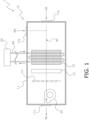
- FIG. 1 is a schematic configuration diagram of the indoor unit 10.
- the indoor unit 10 is an air handling unit.
- the indoor unit 10 mainly includes a casing 11, a centrifugal fan 30, a heat exchanger 12, an electric heater 13, and a humidifier 14.
- the indoor unit 10 and the heat source unit 20 are connected via a pipe 94 through which a heat medium (for example, refrigerant, water, and the like) flows.
- a heat medium for example, refrigerant, water, and the like
- the casing 11 mainly accommodates the centrifugal fan 30, the heat exchanger 12, the electric heater 13, and the humidifier 14.
- the casing 11 is provided with a first opening 11a, a second opening 11b, and a third opening 11c.
- the first opening 11a is an opening for sucking outdoor air OA from outdoors into the casing 11.
- the second opening 11b is an opening for sucking indoor air RA into the target space from the target space into the casing 11.
- the third opening 11c is an opening for blowing out air-conditioned supply air SA from inside of the casing 11 toward the target space.
- the centrifugal fan 30 sucks the outdoor air OA and the indoor air RA into the casing 11 from the first opening 11a and the second opening 11b, and blows the supply air SA toward the target space from the third opening 11c.
- the centrifugal fan 30 generates, in the casing 11, an air flow AF flowing from the first opening 11a and the second opening 11b to the third opening 11c.
- the air flow AF passes through the heat exchanger 12, the electric heater 13, and the humidifier 14 in that order in the casing 11.
- FIG. 3 is a perspective view of the impeller 40.
- the impeller 40 mainly includes a plate 41, a ring 42, and a plurality of blades 43.
- the ring 42 is depicted as translucent.
- the plate 41 is disposed such that a thickness direction of the plate is along a direction of the axis A1.
- the plate 41 is molded with aluminum or an aluminum alloy.
- the plate 41 has a first plate surface 41a facing the ring 42 and a second plate surface 41b opposite to the ring 42.
- FIG. 4 is a diagram of the impeller 40 viewed along the direction of the axis A1 from the plate 41.
- the plate 41 has a ring shape when viewed from the direction of the axis A1.
- An opening 41c for fixing the boss member 44 is formed at a center of the plate 41.
- a hole 41d for fixing the boss member 44 with a bolt is formed around the opening 41c.
- six holes 41d are formed.
- the plate 41 is connected to the fan motor 31 via the fixed boss member 44.
- the ring 42 is disposed apart from the plate 41 in the direction of the axis A1.
- the ring 42 is molded with aluminum or an aluminum alloy.
- the ring 42 has a ring shape when viewed from the direction of the axis A1.
- the ring 42 has a first ring surface 42a facing the plate 41 and a second ring surface 42b opposite to the plate 41.
- the plurality of blades 43 is disposed between the plate 41 and the ring 42.
- the number of the plurality of blades 43 is from seven to eleven.
- the number of blades 43 is nine.
- one end of the plurality of blades 43 is bonded to the first plate surface 41a of the plate 41, and the other end is bonded to the first ring surface 42a of the ring 42.
- the plurality of blades 43 are arranged at unequal pitches along the rotation direction A2 of the impeller 40 (the rotation direction A2 of the plurality of blades 43).
- any one of the plurality of blades 43 will be referred to as a first blade 43a.
- the first blade 43a is molded with resin.
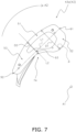
- FIGS. 5 to 7 are diagrams each showing a first bond surface 51 which is a bond surface of the first blade 43a with the plate 41 (a bond surface between the first blade 43a and the first plate surface 41a).
- a hollow portion 71 is formed near the plate 41 in the first blade 43a.
- the first bond surface 51 is located around the hollow portion 71.
- the first bond surface 51 has a shape in which a second concave portion 74 is formed near the axis A1.
- the first bond surface 51 is indicated by hatching.
- the first blade 43a has, on the first bond surface 51, a pin 81 for determining the position of the first blade 43a, and a hole 82 for bringing the first blade 43a into close contact with the first plate surface 41a by passing a screw. As shown in FIG. 5 , in the present embodiment, the first blade 43a has two pins 81 and three holes 82 on the first bond surface 51. The plate 41 and the first blade 43a are bonded by a method other than welding. In the present embodiment, the position of the first blade 43a is determined by the pin 81, the first blade 43a is brought into close contact with the first plate surface 41a by passing a screw, and the plate 41 and the first blade 43a are bonded by an adhesive.
- the first bond surface 51 has a second bond surface 52 and a third bond surface 53.
- a first straight line L1 and a second straight line L2 are defined.
- the structure of the hollow portion 71 is omitted and the first bond surface 51 is depicted so that the first straight line L1, the second straight line L2, and the like can be easily seen.
- the first straight line L1 is a straight line connecting a front end 91 and a rear end 92 of the first blade 43a in the rotation direction A2.
- the second straight line L2 is a straight line that passes through a center 93 of the first straight line L1 and is orthogonal to the first straight line L1.
- the second bond surface 52 is a part of the first bond surface 51 closer to the front end 91 than the second straight line L2.
- the third bond surface 53 is a part of the first bond surface 51 closer to the rear end 92 than the second straight line L2.
- the second bond surface 52 and the third bond surface 53 are indicated by hatching.
- the second bond surface 52 and the third bond surface 53 are distinguished by distinguishing the inclination of the hatched line.
- the first bond surface 51 has a first width dimension D1 and a second width dimension D2.
- the first width dimension D1 is the largest dimension of the width dimensions of the second bond surface 52 along the second straight line L2.
- the second width dimension D2 is the largest dimension of the width dimensions of the third bond surface 53 along the second straight line L2.
- the first width dimension D1 is 1.3 times or more and 3 times or less the second width dimension D2.
- the first width dimension D1 is preferably 1.6 times or more the second width dimension D2.
- FIG. 8 is a diagram showing an eighth bond surface 58 which is a connection surface of the first blade 43a with the ring 42 (a bond surface between the first blade 43a and the first ring surface 42a).
- a hollow portion 72 is formed near the ring 42 in the first blade 43a.
- the eighth bond surface 58 is located around the hollow portion 72.
- the eighth bond surface 58 is indicated by hatching.
- the first blade 43a has, on the eighth bond surface 58, a pin 83 for determining the position of the first blade 43a, and a hole 84 for bringing the first blade 43a into close contact with the first ring surface 42a by passing a screw. As shown in FIG.
- the first blade 43a has one pin 83 and one hole 84 on the eighth bond surface 58.
- the plate 41 and the first blade 43a are bonded by a method other than welding.
- the position of the first blade 43a is determined by the pin 83, the first blade 43a is brought into close contact with the first ring surface 42a by passing a screw, and the ring 42 and the first blade 43a are bonded by an adhesive.
- FIG. 9 is a diagram of the first blade 43a extending from the plate 41 to the ring 42 as viewed along the first straight line L1. As shown in FIG. 9 , when the first blade 43a extending from the plate 41 to the ring 42 is viewed along the first straight line L1, the shape of the first blade 43a includes the first concave portion 73. The first concave portion 73 is formed at a position closer to the plate 41 than the ring 42.
- the diameter of the impeller 40 having the first blade 43a and the diameter of the conventional impeller having the blade 43' are unified to 500 mm.
- the number of the first blades 43a and the number of the blades 43' are unified to nine.
- the arrangement of the first blades 43a in the impeller 40 is substantially the same as the arrangement of blades 43' in the conventional impeller.
- the mass of the first blade 43a is 1200 g, and the mass of the blade 43' is 1324 g.
- FIGS. 10 and 11 are diagrams showing a first bond surface 51' which is a bond surface of the conventional blade 43' with the plate. As shown in FIG. 10 , unlike the first blade 43a, no hollow portion is formed near the plate in the blade 43'. In FIG. 10 , a rotation direction of the blade 43' is indicated as "A2"'. In FIG. 10 , the first bond surface 51' is indicated by hatching. Similarly to the first blade 43a, the blade 43' is molded by resin, and the plate and the blade 43' are bonded by an adhesive. FIG. 11 shows a first straight line L1', a second straight line L2', a first width dimension D1', and a second width dimension D2' of the first bond surface 51'.
- a second bond surface 52' is indicated by hatching.
- the area of the first bond surface 51 of the first blade 43a is 9250.63 mm 2
- the area of the first bond surface 51' of the blade 43' is 9341.27 mm 2 .
- the first width dimension D1 of the first blade 43a is 82.29 mm
- the first width dimension D1' of the blade 43' is 57 mm.
- the second width dimension D2 of the first blade 43a is 49.99 mm
- the second width dimension D2' of the blade 43' is 53.06 mm.
- the first width dimension D1 is 1.65 times the second width dimension D2
- the first width dimension D1' is 1.07 times the second width dimension D2'.
- the number of breaking rotations of the first blade 43a is 3500 rpm
- the number of breaking rotations of the blade 43' is 2300 rpm.
- a maximum stress generated on a surface of the first blade 43a (excluding the bond surface with the plate 41 and the ring 42) is 25 MPa, and a maximum stress generated on a surface of the blade 43' (excluding the bond surface with the plate and the ring) is 28 MPa.
- the maximum stress generated on the surface (excluding the bond surface between the plate 41 and the ring 42) of the first blade 43a is 44 MPa.
- a maximum normal stress generated on the first bond surface 51 of the first blade 43a is 8.25 MPa
- a maximum normal stress generated on the first bond surface 51' of the blade 43' is 17.8 MPa.
- the maximum normal stress generated on the first bond surface 51 of the first blade 43a is 15 MPa.
- a location where the maximum normal stress is generated on the first bond surface 51 of the first blade 43a is indicated as "P”.
- a location where the maximum normal stress is generated on the first bond surface 51' of the blade 43' is indicated as "P"'.
- the locations P and P' where the maximum normal stress occurs are both located near the axes A1 and A1' on the second bond surfaces 52 and 52'.
- the value of the "maximum normal stress (Table 2) generated on the first bond surface” is smaller in the first blade 43a than in the blade 43' (even the value of the maximum normal stress occurring on the first bond surface 51 when the number of rotations is 3100 rpm is smaller than the value of the maximum normal stress occurring on the first bond surface 51' when the number of rotations is 2300 rpm). Since the location P where the maximum normal stress is generated on the first bond surface 51 is closer to the axis than the location P' where the maximum normal stress is generated on the first bond surface 51', it is presumed that the value of the maximum normal stress decreases as the location where the maximum normal stress is generated is closer to the axis.
- the blade is peeled off from the second bond surface near the axis due to the centrifugal force.
- a location where the maximum normal stress is generated becomes closer to the axis, and the value of the maximum normal stress also decreases, and thus, the blade is less likely to be peeled off.
- a centrifugal fan including a plate disposed such that a thickness direction of the plate is along a direction of an axis, a ring disposed apart from the plate in the direction of the axis and having a ring shape when viewed from the direction of the axis, and a plurality of blades disposed between the plate and the ring and having one end bonded to the plate and the other end bonded to the ring.
- centrifugal fan Since the centrifugal fan has a blade rotating at a high speed, a large centrifugal force acts on the blade. It is therefore desirable to further increase the bonding strength between the blade and the plate.
- the centrifugal fan 30 includes the plate 41, the ring 42, and the plurality of blades 43.
- the plate 41 is disposed such that the thickness direction of the plate 41 is along the direction of the axis A1.
- the ring 42 is disposed apart from the plate 41 in the direction of the axis A1.
- the ring 42 has a ring shape when viewed from the direction of the axis A1.
- the plurality of blades 43 is disposed between the plate 41 and the ring 42.
- the plurality of blades 43 has one end bonded to the plate 41 and the other end bonded to the ring 42.
- the plurality of blades 43 includes the first blade 43a.
- the first bond surface 51 is a bond surface of the first blade 43a with the plate 41.
- the first bond surface 51 has a second bond surface 52 and a third bond surface 53.
- the second bond surface 52 is a part of the first bond surface 51 closer to the front end 91 than the second straight line L2.
- the second straight line L2 passes through a center 93 of the first straight line L1 and is orthogonal to the first straight line L1.
- the first straight line L1 connects the front end 91 and the rear end 92 of the first blade 43a in the rotation direction A2.
- the third bond surface 53 is a part of the first bond surface 51 closer to the rear end 92 than the second straight line L2.
- the first width dimension D1 is the largest width dimension of the width dimensions of the second bond surface 52 along the second straight line L2.
- the second width dimension D2 is the largest width dimension of the width dimensions of the third bond surface 53 along the second straight line L2.
- the first width dimension D1 is 1.3 times or more the second width dimension D2.
- the centrifugal fan 30 By expanding the second bond surface 52 as a part of the first blade 43a near the front end 91 in the rotation direction A2 toward the axis A1, the value of the maximum normal stress generated on the first bond surface 51 by the centrifugal force tends to decrease.
- the first width dimension D1 is 1.3 times or more the second width dimension D2.
- the first width dimension D1 is the largest width dimension of the width dimensions of the second bond surface 52 along the second straight line L2.
- the second width dimension D2 is the largest width dimension of the width dimensions of the third bond surface 53 along the second straight line L2.
- the area of a fourth bond surface 54 as a part of the second bond surface 52 closer to the rotation axis A1 than the first straight line L1 may be larger than the area of a fifth bond surface 55 as a part of the second bond surface 52 opposite to the axis A1.
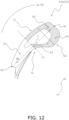
- FIG. 12 is a diagram of the fourth bond surface 54 and the fifth bond surface 55.
- the fourth bond surface 54 and the fifth bond surface 55 are indicated by hatching.
- the fourth bond surface 54 and the fifth bond surface 55 are distinguished by distinguishing the inclination of the hatched line.
- the first blade 43a tends to be peeled off from the fourth bond surface 54 as a part of the second bond surface 52 near the axis A1 due to the centrifugal force. Therefore, in the centrifugal fan 30, by making the area of the fourth bond surface 54 larger than the area of the fifth bond surface 55 in the second bond surface 52, the bonding strength between the first blade 43a and the plate 41 can be increased.
- the area of a fourth bond surface 54 as a part of the second bond surface 52 closer to the rotation axis A1 than the first straight line L1 may be larger than the area of a sixth bond surface 56 as a part of the third bond surface 53 closer to the axis A1 than the first straight line L1.
- FIG. 13 is a diagram of the fourth bond surface 54 and the sixth bond surface 56.
- the fourth bond surface 54 and the sixth bond surface 56 are indicated by hatching.
- the fourth bond surface 54 and the sixth bond surface 56 are distinguished by distinguishing the inclination of the hatched line.
- the first blade 43a tends to be peeled off from the fourth bond surface as a part of the second bond surface 52 near the axis A1 due to the centrifugal force. Therefore, in the centrifugal fan 30, by making the area of the fourth bond surface 54 larger than the area of the sixth bond surface 56, the bonding strength between the first blade 43a and the plate 41 can be increased.
- FIG. 14 is an enlarged view of the first bond surface 51 of the first blade 43a and the seventh bond surface 57 of the second blade 43b.
- the seventh bond surface 57 may be located outside a region surrounded by the second concave portion 74 of the first bond surface 51 and the third straight line L3 connecting both ends of the second concave portion 74.
- the plate 41 tends to be deformed accordingly. At this time, if the first blade 43a and the second blade 43b are in close contact with each other, the plate 41 cannot be deformed, and a large load is applied to the first bond surface 51 and the seventh bond surface 57.
- the seventh bond surface 57 is located outside a region surrounded by the second concave portion 74 and the third straight line L3 connecting both ends of the second concave portion 74.
- the plate 41 can be deformed in accordance with the deformation of the first blade 43a and the second blade 43b due to the centrifugal force, and thus, a large load is not applied to the first bond surface 51 and the seventh bond surface 57.
- the centrifugal fan 30 can increase the bonding strength between the first blade 43a and the plate 41 and between the second blade 43b and the plate 41.
- the plate 41 and the ring 42 are molded with aluminum or an aluminum alloy.
- the plate 41 and the ring 42 may be molded with resin, similarly to the blades 43.
- the centrifugal fan 30 is a turbofan used for an air handling unit.
- the centrifugal fan 30 may be used in any device as a turbofan such as, for example, a turbofan used for a fan coil unit, or a turbofan used as a ventilation fan or a humidification fan in a household outdoor unit.
- Patent Literature 1 JP 2019-100209 A
Landscapes
- Engineering & Computer Science (AREA)
- Mechanical Engineering (AREA)
- General Engineering & Computer Science (AREA)
- Structures Of Non-Positive Displacement Pumps (AREA)
Abstract
Description
- The present disclosure relates to a centrifugal fan.
- As disclosed in Patent Document 1 (
JP 2019-100209 A - Since the centrifugal fan has a blade rotating at a high speed, a large centrifugal force acts on the blade. It is therefore desirable to further increase a bonding strength between the blade and the plate.
- A centrifugal fan according to a first aspect includes a plate, a ring, and a plurality of blades. The plate is disposed such that a thickness direction of the plate is along a direction of an axis. The ring is disposed apart from the plate in the direction of the axis. The ring has a ring shape when viewed from the direction of the axis. The plurality of blades is disposed between the plate and the ring. The plurality of blades has one end bonded to the plate and the other end bonded to the ring. The plurality of blades includes a first blade. A first bond surface is a bond surface of the first blade with the plate. The first bond surface has a second bond surface and a third bond surface. The second bond surface is a part of the first bond surface closer to a front end than a second straight line. The second straight line is a straight line that passes through a center of a first straight line and is orthogonal to the first straight line. The first straight line connects the front end and a rear end of the first blade in a rotation direction. The third bond surface is a part of the first bond surface closer to the rear end than the second straight line. A first width dimension is the largest dimension of width dimensions of the second bond surface along the second straight line. A second width dimension is the largest dimension of width dimensions of the third bond surface along the second straight line. The first width dimension is 1.3 times or more the second width dimension.
- By expanding the second bond surface as a part of the first blade near the front end in the rotation direction toward the axis, the value of a maximum normal stress generated on the first bond surface by a centrifugal force tends to decrease. In the centrifugal fan according to the first aspect, the first width dimension is 1.3 times or more the second width dimension. A first width dimension is the largest dimension of width dimensions of the second bond surface along the second straight line. A second width dimension is the largest dimension of width dimensions of the third bond surface along the second straight line. As a result, the centrifugal fan can increase a bonding strength between the first blade and the plate.
- A centrifugal fan according to a second aspect is the centrifugal fan according to the first aspect, in which the first width dimension is three times or less the second width dimension.
- A centrifugal fan according to a third aspect is the centrifugal fan according to the first or second aspect, in which the first width dimension is 1.6 times or more the second width dimension.
- A centrifugal fan according to a fourth aspect is a centrifugal fan according to any of the first to third aspects, in which an area of a fourth bond surface as a part of the second bond surface closer to the axis than the first straight line is larger than an area of a fifth bond surface as a part of the second bond surface opposite to the axis.
- The
first blade 43a tends to be peeled off from the fourth bond surface as a part of the second bond surface near the axis due to the centrifugal force. In the centrifugal fan according to the fourth aspect, by making the area of the fourth bond surface larger than the area of the fifth bond surface in the second bond surface, the bonding strength between the first blade and the plate can be increased. - A centrifugal fan according to a fifth aspect is the centrifugal fan according to any of the first to fourth aspects, in which an area of a fourth bond surface as a part of the second bond surface closer to the axis than the first straight line is larger than an area of a sixth bond surface as a part of the third bond surface closer to the axis than the first straight line.
- The
first blade 43a tends to be peeled off from the fourth bond surface as a part of the second bond surface near the axis due to the centrifugal force. In the centrifugal fan according to the fifth aspect, by making the area of the fourth bond surface larger than the area of the sixth bond surface, the bonding strength between the first blade and the plate can be increased. - A centrifugal fan according to a sixth aspect is the centrifugal fan according to any of the first to fifth aspects, in which when the first blade extending from the plate to the ring is viewed along the first straight line, a shape of the first blade includes a first concave portion.
- A centrifugal fan according to a seventh aspect is the centrifugal fan according to the sixth aspect, in which the first concave portion is formed at a position closer to the plate than the ring.
- With such a configuration, the centrifugal fan according to the seventh aspect can secure the first width dimension without affecting performance of the centrifugal fan.
- A centrifugal fan according to an eighth aspect is the centrifugal fan according to any of the first to seventh aspects, in which the plurality of blades includes a second blade adjacent to the first blade. The first bond surface has a shape in which a second concave portion is formed near the axis. A seventh bond surface is located outside a region surrounded by the second concave portion and a third straight line connecting both ends of the second concave portion. The seventh bond surface is a bond surface of the second blade with the plate.
- When the first blade and the second blade are deformed by the centrifugal force, the plate tends to be deformed accordingly. At this time, if the first blade and the second blade are in close contact with each other, the plate cannot be deformed, and a large load is applied to the first bond surface and the seventh bond surface. In the centrifugal fan according to the eighth aspect, the seventh bond surface is located outside a region surrounded by the second concave portion and the third straight line connecting both ends of the second concave portion. Therefore, in the centrifugal fan, the plate can be deformed in accordance with the deformation of the first blade and the second blade due to the centrifugal force, and thus, a large load is not applied to the first bond surface and the seventh bond surface. As a result, the centrifugal fan can increase the bonding strength between the first blade and the plate and between the second blade and the plate.
- A centrifugal fan according to a ninth aspect is the centrifugal fan according to any of the first to eighth aspects, in which the first bond surface is located around a hollow portion formed near the plate in the first blade.
- The centrifugal fan according to the ninth aspect, which is provided with the hollow portion to lighten the first blade, can weaken the centrifugal force acting on the first blade.
- A centrifugal fan according to a tenth aspect is the centrifugal fan according to any of the first to ninth aspects, in which the first blade is molded with resin.
- The centrifugal fan according to the tenth aspect, in which the first blade is molded by injection molding or the like, can increase a degree of freedom of the shape of the first blade.
- A centrifugal fan according to an eleventh aspect is the centrifugal fan according to any of the first to tenth aspects, in which the plate and the ring are molded with aluminum or an aluminum alloy.
- A centrifugal fan according to a twelfth aspect is the centrifugal fan according to any of the first to eleventh aspects, in which the plate and the first blade are bonded by a method other than welding.
- The centrifugal fan according to the twelfth aspect does not require a space for accommodating a welding torch, so that the number of the plurality of blades can be increased to eliminate Nz sound.
- A centrifugal fan according to a thirteenth aspect is the centrifugal fan according to any of the first to twelfth aspects, in which the number of the plurality of blades is from seven to eleven.
-
-
FIG. 1 is a schematic configuration diagram of an indoor unit. -
FIG. 2 is a schematic sectional view of a centrifugal fan. -
FIG. 3 is a perspective view of an impeller. -
FIG. 4 is a diagram of the impeller viewed along a direction of an axis from a plate. -
FIG. 5 is a diagram of a first bond surface which is a bond surface of a first blade with the plate. -
FIG. 6 is a diagram of the first bond surface which is a bond surface of the first blade with the plate. -
FIG. 7 is a diagram of the first bond surface which is a bond surface of the first blade with the plate. -
FIG. 8 is a diagram of an eighth bond surface which is a bond surface of the first blade with a ring. -
FIG. 9 is a diagram of the first blade extending from the plate to the ring as viewed along a first straight line. -
FIG. 10 is a diagram of a first bond surface which is a bond surface of a conventional blade with a plate. -
FIG. 11 is a diagram of the first bond surface which is a bond surface of the conventional blade with the plate. -
FIG. 12 is a diagram of a fourth bond surface and a fifth bond surface. -
FIG. 13 is a diagram of the fourth bond surface and a sixth bond surface. -
FIG. 14 is an enlarged view of the first bond surface of the first blade and a seventh bond surface of a second blade. - An
air conditioner 1 performs air conditioning of a target space by using a vapor compression refrigeration cycle. In the present embodiment, theair conditioner 1 is a central air conditioner. Theair conditioner 1 mainly includes anindoor unit 10 and aheat source unit 20. -
FIG. 1 is a schematic configuration diagram of theindoor unit 10. In the present embodiment, theindoor unit 10 is an air handling unit. As shown inFIG. 1 , theindoor unit 10 mainly includes acasing 11, acentrifugal fan 30, aheat exchanger 12, anelectric heater 13, and ahumidifier 14. Theindoor unit 10 and theheat source unit 20 are connected via apipe 94 through which a heat medium (for example, refrigerant, water, and the like) flows. - The
casing 11 mainly accommodates thecentrifugal fan 30, theheat exchanger 12, theelectric heater 13, and thehumidifier 14. Thecasing 11 is provided with afirst opening 11a, asecond opening 11b, and athird opening 11c. Thefirst opening 11a is an opening for sucking outdoor air OA from outdoors into thecasing 11. Thesecond opening 11b is an opening for sucking indoor air RA into the target space from the target space into thecasing 11. Thethird opening 11c is an opening for blowing out air-conditioned supply air SA from inside of thecasing 11 toward the target space. - The
centrifugal fan 30 sucks the outdoor air OA and the indoor air RA into thecasing 11 from thefirst opening 11a and thesecond opening 11b, and blows the supply air SA toward the target space from thethird opening 11c. Thecentrifugal fan 30 generates, in thecasing 11, an air flow AF flowing from thefirst opening 11a and thesecond opening 11b to thethird opening 11c. The air flow AF passes through theheat exchanger 12, theelectric heater 13, and thehumidifier 14 in that order in thecasing 11. - The
heat exchanger 12, theelectric heater 13, and thehumidifier 14 are disposed in a flow path of the air flow AF. Theheat exchanger 12 causes heat exchange between the air flow AF and the heat medium in thepipe 94 supplied from theheat source unit 20. Theelectric heater 13 heats the air flow AF that has passed through theheat exchanger 12. Thehumidifier 14 humidifies the air flow AF by spraying water in a tank (not shown) installed outside thecasing 11 from a nozzle. -
FIG. 2 is a schematic sectional view of thecentrifugal fan 30. In the present embodiment, thecentrifugal fan 30 is a turbofan. As shown inFIG. 2 , thecentrifugal fan 30 mainly includes afan motor 31 and animpeller 40. Theimpeller 40 is connected to thefan motor 31 via a boss member 44. Theimpeller 40 rotates around rotation an axis A1 by using thefan motor 31 as power. InFIG. 2 , a rotation direction of theimpeller 40 is indicated as "A2". -
FIG. 3 is a perspective view of theimpeller 40. As shown inFIG. 3 , theimpeller 40 mainly includes aplate 41, aring 42, and a plurality ofblades 43. InFIG. 3 , thering 42 is depicted as translucent. - As shown in
FIGS. 2 and3 , theplate 41 is disposed such that a thickness direction of the plate is along a direction of the axis A1. Theplate 41 is molded with aluminum or an aluminum alloy. As shown inFIG. 2 , theplate 41 has afirst plate surface 41a facing thering 42 and asecond plate surface 41b opposite to thering 42.FIG. 4 is a diagram of theimpeller 40 viewed along the direction of the axis A1 from theplate 41. As shown inFIG. 4 , theplate 41 has a ring shape when viewed from the direction of the axis A1. Anopening 41c for fixing the boss member 44 is formed at a center of theplate 41. Ahole 41d for fixing the boss member 44 with a bolt is formed around theopening 41c. As shown inFIG. 4 , in the present embodiment, sixholes 41d are formed. Theplate 41 is connected to thefan motor 31 via the fixed boss member 44. - As shown in
FIGS. 2 and3 , thering 42 is disposed apart from theplate 41 in the direction of the axis A1. Thering 42 is molded with aluminum or an aluminum alloy. As shown inFIG. 3 , thering 42 has a ring shape when viewed from the direction of the axis A1. As shown inFIG. 2 , thering 42 has afirst ring surface 42a facing theplate 41 and asecond ring surface 42b opposite to theplate 41. - As shown in
FIGS. 2 and3 , the plurality ofblades 43 is disposed between theplate 41 and thering 42. The number of the plurality ofblades 43 is from seven to eleven. As shown inFIGS. 3 and4 , in the present embodiment, the number ofblades 43 is nine. As shown inFIG. 2 , one end of the plurality ofblades 43 is bonded to thefirst plate surface 41a of theplate 41, and the other end is bonded to thefirst ring surface 42a of thering 42. As shown inFIGS. 3 and4 , the plurality ofblades 43 are arranged at unequal pitches along the rotation direction A2 of the impeller 40 (the rotation direction A2 of the plurality of blades 43). - Hereinafter, any one of the plurality of
blades 43 will be referred to as afirst blade 43a. Thefirst blade 43a is molded with resin. -
FIGS. 5 to 7 are diagrams each showing afirst bond surface 51 which is a bond surface of thefirst blade 43a with the plate 41 (a bond surface between thefirst blade 43a and thefirst plate surface 41a). As shown inFIG. 5 , ahollow portion 71 is formed near theplate 41 in thefirst blade 43a. Thefirst bond surface 51 is located around thehollow portion 71. Thefirst bond surface 51 has a shape in which a secondconcave portion 74 is formed near the axis A1. InFIG. 5 , thefirst bond surface 51 is indicated by hatching. Thefirst blade 43a has, on thefirst bond surface 51, apin 81 for determining the position of thefirst blade 43a, and ahole 82 for bringing thefirst blade 43a into close contact with thefirst plate surface 41a by passing a screw. As shown inFIG. 5 , in the present embodiment, thefirst blade 43a has twopins 81 and threeholes 82 on thefirst bond surface 51. Theplate 41 and thefirst blade 43a are bonded by a method other than welding. In the present embodiment, the position of thefirst blade 43a is determined by thepin 81, thefirst blade 43a is brought into close contact with thefirst plate surface 41a by passing a screw, and theplate 41 and thefirst blade 43a are bonded by an adhesive. - The
first bond surface 51 has asecond bond surface 52 and athird bond surface 53. Here, in order to describe thesecond bond surface 52 and thethird bond surface 53, a first straight line L1 and a second straight line L2 are defined. InFIGS. 6 and7 , the structure of thehollow portion 71 is omitted and thefirst bond surface 51 is depicted so that the first straight line L1, the second straight line L2, and the like can be easily seen. As shown inFIG. 6 , the first straight line L1 is a straight line connecting afront end 91 and arear end 92 of thefirst blade 43a in the rotation direction A2. The second straight line L2 is a straight line that passes through acenter 93 of the first straight line L1 and is orthogonal to the first straight line L1. Thesecond bond surface 52 is a part of thefirst bond surface 51 closer to thefront end 91 than the second straight line L2. Thethird bond surface 53 is a part of thefirst bond surface 51 closer to therear end 92 than the second straight line L2. InFIG. 6 , thesecond bond surface 52 and thethird bond surface 53 are indicated by hatching. InFIG. 6 , thesecond bond surface 52 and thethird bond surface 53 are distinguished by distinguishing the inclination of the hatched line. - Furthermore, the
first bond surface 51 has a first width dimension D1 and a second width dimension D2. As shown inFIG. 7 , the first width dimension D1 is the largest dimension of the width dimensions of thesecond bond surface 52 along the second straight line L2. The second width dimension D2 is the largest dimension of the width dimensions of thethird bond surface 53 along the second straight line L2. The first width dimension D1 is 1.3 times or more and 3 times or less the second width dimension D2. The first width dimension D1 is preferably 1.6 times or more the second width dimension D2. -
FIG. 8 is a diagram showing aneighth bond surface 58 which is a connection surface of thefirst blade 43a with the ring 42 (a bond surface between thefirst blade 43a and thefirst ring surface 42a). As shown inFIG. 8 , ahollow portion 72 is formed near thering 42 in thefirst blade 43a. Theeighth bond surface 58 is located around thehollow portion 72. InFIG. 8 , theeighth bond surface 58 is indicated by hatching. Thefirst blade 43a has, on theeighth bond surface 58, apin 83 for determining the position of thefirst blade 43a, and ahole 84 for bringing thefirst blade 43a into close contact with thefirst ring surface 42a by passing a screw. As shown inFIG. 8 , in the present embodiment, thefirst blade 43a has onepin 83 and onehole 84 on theeighth bond surface 58. Theplate 41 and thefirst blade 43a are bonded by a method other than welding. In the present embodiment, the position of thefirst blade 43a is determined by thepin 83, thefirst blade 43a is brought into close contact with thefirst ring surface 42a by passing a screw, and thering 42 and thefirst blade 43a are bonded by an adhesive. -
FIG. 9 is a diagram of thefirst blade 43a extending from theplate 41 to thering 42 as viewed along the first straight line L1. As shown inFIG. 9 , when thefirst blade 43a extending from theplate 41 to thering 42 is viewed along the first straight line L1, the shape of thefirst blade 43a includes the firstconcave portion 73. The firstconcave portion 73 is formed at a position closer to theplate 41 than thering 42. - Here, by using the
first blade 43a in the present embodiment and a blade 43' used in a conventional turbofan, the number of rotations (number of breaking rotations) when the blade is broken by a centrifugal force has been verified. For this verification, simulation software "ANSYS" is used. - The specifications of the
first blade 43a and the blade 43' in this verification are shown in Table 1 below.[Table 1] First blade 43aBlade 43' Diameter of impeller [mm] 500 Number of blades 9 Mass [g] 1200 1324 Area of first bond surface [mm2] 9250.63 9341.27 First width dimension [mm] 82.29 57 Second width dimension [mm] 49.99 53.06 First width dimension/Second width dimension 1.65 1.07 - As shown in Table 1, in this verification, the diameter of the
impeller 40 having thefirst blade 43a and the diameter of the conventional impeller having the blade 43' are unified to 500 mm. The number of thefirst blades 43a and the number of the blades 43' are unified to nine. The arrangement of thefirst blades 43a in theimpeller 40 is substantially the same as the arrangement of blades 43' in the conventional impeller. - The mass of the
first blade 43a is 1200 g, and the mass of the blade 43' is 1324 g. -
FIGS. 10 and11 are diagrams showing a first bond surface 51' which is a bond surface of the conventional blade 43' with the plate. As shown inFIG. 10 , unlike thefirst blade 43a, no hollow portion is formed near the plate in the blade 43'. InFIG. 10 , a rotation direction of the blade 43' is indicated as "A2"'. InFIG. 10 , the first bond surface 51' is indicated by hatching. Similarly to thefirst blade 43a, the blade 43' is molded by resin, and the plate and the blade 43' are bonded by an adhesive.FIG. 11 shows a first straight line L1', a second straight line L2', a first width dimension D1', and a second width dimension D2' of the first bond surface 51'. For later description, inFIG. 11 , a second bond surface 52' is indicated by hatching. The area of thefirst bond surface 51 of thefirst blade 43a is 9250.63 mm2, and the area of the first bond surface 51' of the blade 43' is 9341.27 mm2. The first width dimension D1 of thefirst blade 43a is 82.29 mm, and the first width dimension D1' of the blade 43' is 57 mm. The second width dimension D2 of thefirst blade 43a is 49.99 mm, and the second width dimension D2' of the blade 43' is 53.06 mm. In thefirst blade 43a, the first width dimension D1 is 1.65 times the second width dimension D2, and in the blade 43', the first width dimension D1' is 1.07 times the second width dimension D2'. - The verification results are shown in Table 2 below.
[Table 2] First blade 43 aBlade 43' Number of breaking rotations [rpm] 3500 2300 Maximum stress generated on surface of blade [MPa] 25 (At 2300 rpm) 28 (At 2300 rpm) 44 (At 3100 rpm) Maximum normal stress generated on first bond surface [MPa] 8.25 (At 2300 rpm) 17.8 (At 2300 rpm) 15 (At 3100 rpm) - As shown in Table 2, the number of breaking rotations of the
first blade 43a is 3500 rpm, and the number of breaking rotations of the blade 43' is 2300 rpm. - When the number of rotations is 2300 rpm, a maximum stress generated on a surface of the
first blade 43a (excluding the bond surface with theplate 41 and the ring 42) is 25 MPa, and a maximum stress generated on a surface of the blade 43' (excluding the bond surface with the plate and the ring) is 28 MPa. When the number of rotations is 3100 rpm, the maximum stress generated on the surface (excluding the bond surface between theplate 41 and the ring 42) of thefirst blade 43a is 44 MPa. - When the number of rotations is 2300 rpm, a maximum normal stress generated on the
first bond surface 51 of thefirst blade 43a is 8.25 MPa, and a maximum normal stress generated on the first bond surface 51' of the blade 43' is 17.8 MPa. When the number of rotations is 3100 rpm, the maximum normal stress generated on thefirst bond surface 51 of thefirst blade 43a is 15 MPa. InFIG. 7 , a location where the maximum normal stress is generated on thefirst bond surface 51 of thefirst blade 43a is indicated as "P". InFIG. 11 , a location where the maximum normal stress is generated on the first bond surface 51' of the blade 43' is indicated as "P"'. - As shown in
FIGS. 7 and11 , in the first bond surfaces 51 and 51', the locations P and P' where the maximum normal stress occurs are both located near the axes A1 and A1' on the second bond surfaces 52 and 52'. - On the other hand, the value of the "maximum normal stress (Table 2) generated on the first bond surface" is smaller in the
first blade 43a than in the blade 43' (even the value of the maximum normal stress occurring on thefirst bond surface 51 when the number of rotations is 3100 rpm is smaller than the value of the maximum normal stress occurring on the first bond surface 51' when the number of rotations is 2300 rpm). Since the location P where the maximum normal stress is generated on thefirst bond surface 51 is closer to the axis than the location P' where the maximum normal stress is generated on the first bond surface 51', it is presumed that the value of the maximum normal stress decreases as the location where the maximum normal stress is generated is closer to the axis. - Therefore, the blade is peeled off from the second bond surface near the axis due to the centrifugal force. However, it is presumed that when the second bond surface is expanded toward the axis, a location where the maximum normal stress is generated becomes closer to the axis, and the value of the maximum normal stress also decreases, and thus, the blade is less likely to be peeled off.
- As a result, it is presumed that one of the factors that the
first blade 43a has a larger value of "number of breaking rotations (Table 2)" than the blade 43' is that thefirst blade 43a has a larger value of "first width dimension/second width dimension (Table 1)" than the blade 43'. - (5-1) Conventionally, there is known a centrifugal fan including a plate disposed such that a thickness direction of the plate is along a direction of an axis, a ring disposed apart from the plate in the direction of the axis and having a ring shape when viewed from the direction of the axis, and a plurality of blades disposed between the plate and the ring and having one end bonded to the plate and the other end bonded to the ring.
- Since the centrifugal fan has a blade rotating at a high speed, a large centrifugal force acts on the blade. It is therefore desirable to further increase the bonding strength between the blade and the plate.
- The
centrifugal fan 30 according to the present embodiment includes theplate 41, thering 42, and the plurality ofblades 43. Theplate 41 is disposed such that the thickness direction of theplate 41 is along the direction of the axis A1. Thering 42 is disposed apart from theplate 41 in the direction of the axis A1. Thering 42 has a ring shape when viewed from the direction of the axis A1. The plurality ofblades 43 is disposed between theplate 41 and thering 42. The plurality ofblades 43 has one end bonded to theplate 41 and the other end bonded to thering 42. The plurality ofblades 43 includes thefirst blade 43a. Thefirst bond surface 51 is a bond surface of thefirst blade 43a with theplate 41. Thefirst bond surface 51 has asecond bond surface 52 and athird bond surface 53. Thesecond bond surface 52 is a part of thefirst bond surface 51 closer to thefront end 91 than the second straight line L2. The second straight line L2 passes through acenter 93 of the first straight line L1 and is orthogonal to the first straight line L1. The first straight line L1 connects thefront end 91 and therear end 92 of thefirst blade 43a in the rotation direction A2. Thethird bond surface 53 is a part of thefirst bond surface 51 closer to therear end 92 than the second straight line L2. The first width dimension D1 is the largest width dimension of the width dimensions of thesecond bond surface 52 along the second straight line L2. The second width dimension D2 is the largest width dimension of the width dimensions of thethird bond surface 53 along the second straight line L2. The first width dimension D1 is 1.3 times or more the second width dimension D2. - By expanding the
second bond surface 52 as a part of thefirst blade 43a near thefront end 91 in the rotation direction A2 toward the axis A1, the value of the maximum normal stress generated on thefirst bond surface 51 by the centrifugal force tends to decrease. In thecentrifugal fan 30 according to the present embodiment, the first width dimension D1 is 1.3 times or more the second width dimension D2. The first width dimension D1 is the largest width dimension of the width dimensions of thesecond bond surface 52 along the second straight line L2. The second width dimension D2 is the largest width dimension of the width dimensions of thethird bond surface 53 along the second straight line L2. As a result, thecentrifugal fan 30 can increase the bonding strength between thefirst blade 43a and theplate 41. - (5-2) In the
centrifugal fan 30 according to the present embodiment, the first width dimension D1 is three times or less the second width dimension D2. - (5-3) In the
centrifugal fan 30 according to the present embodiment, the first width dimension D1 is 1.6 times or more the second width dimension D2. - (5-4) In the
centrifugal fan 30 according to the present embodiment, when thefirst blade 43a extending from theplate 41 to thering 42 is viewed along the first straight line L1, the shape of thefirst blade 43a includes the firstconcave portion 73. - (5-5) In the
centrifugal fan 30 according to the present embodiment, the firstconcave portion 73 is formed at a position closer to theplate 41 than thering 42. As a result, thecentrifugal fan 30 can secure the first width dimension D1 without affecting performance of thecentrifugal fan 30. - (5-6) In the
centrifugal fan 30 according to the present embodiment, thefirst bond surface 51 is located around thehollow portion 71 formed near theplate 41 in thefirst blade 43a. As a result, thecentrifugal fan 30, which is provided with thehollow portion 71 to lighten thefirst blade 43a, can weaken the centrifugal force acting on thefirst blade 43a. - (5-7) In the
centrifugal fan 30 according to the present embodiment, thefirst blade 43a is molded with resin. As a result, thecentrifugal fan 30, in which thefirst blade 43a is molded by injection molding or the like, can increase a degree of freedom of the shape of thefirst blade 43a. - (5-8) In the
centrifugal fan 30 according to the present embodiment, theplate 41 and thering 42 are molded with aluminum or an aluminum alloy. - (5-9) In the
centrifugal fan 30 according to the present embodiment, theplate 41 and thefirst blade 43a are bonded by a method other than welding. As a result, thecentrifugal fan 30 does not require a space for accommodating a welding torch, so that the number of the plurality ofblades 43 can be increased to eliminate Nz sound. - (5-10) In the
centrifugal fan 30 according to the present embodiment, the number of the plurality ofblades 43 is from seven to eleven. - The area of a
fourth bond surface 54 as a part of thesecond bond surface 52 closer to the rotation axis A1 than the first straight line L1 may be larger than the area of afifth bond surface 55 as a part of thesecond bond surface 52 opposite to the axis A1. -
FIG. 12 is a diagram of thefourth bond surface 54 and thefifth bond surface 55. InFIG. 12 , thefourth bond surface 54 and thefifth bond surface 55 are indicated by hatching. InFIG. 12 , thefourth bond surface 54 and thefifth bond surface 55 are distinguished by distinguishing the inclination of the hatched line. - The
first blade 43a tends to be peeled off from thefourth bond surface 54 as a part of thesecond bond surface 52 near the axis A1 due to the centrifugal force. Therefore, in thecentrifugal fan 30, by making the area of thefourth bond surface 54 larger than the area of thefifth bond surface 55 in thesecond bond surface 52, the bonding strength between thefirst blade 43a and theplate 41 can be increased. - The area of a
fourth bond surface 54 as a part of thesecond bond surface 52 closer to the rotation axis A1 than the first straight line L1 may be larger than the area of asixth bond surface 56 as a part of thethird bond surface 53 closer to the axis A1 than the first straight line L1. -
FIG. 13 is a diagram of thefourth bond surface 54 and thesixth bond surface 56. InFIG. 13 , thefourth bond surface 54 and thesixth bond surface 56 are indicated by hatching. InFIG. 13 , thefourth bond surface 54 and thesixth bond surface 56 are distinguished by distinguishing the inclination of the hatched line. - The
first blade 43a tends to be peeled off from the fourth bond surface as a part of thesecond bond surface 52 near the axis A1 due to the centrifugal force. Therefore, in thecentrifugal fan 30, by making the area of thefourth bond surface 54 larger than the area of thesixth bond surface 56, the bonding strength between thefirst blade 43a and theplate 41 can be increased. - Hereinafter, any one blade adjacent to the
first blade 43a of the plurality ofblades 43 will be referred to as asecond blade 43b. The bond surface of thesecond blade 43b with the plate 41 (bond surface between thesecond blade 43b and thefirst plate surface 41a) is referred to as aseventh bond surface 57.FIG. 14 is an enlarged view of thefirst bond surface 51 of thefirst blade 43a and theseventh bond surface 57 of thesecond blade 43b. - At this time, as shown in
FIG. 14 , theseventh bond surface 57 may be located outside a region surrounded by the secondconcave portion 74 of thefirst bond surface 51 and the third straight line L3 connecting both ends of the secondconcave portion 74. - When the
first blade 43a and thesecond blade 43b are deformed by the centrifugal force, theplate 41 tends to be deformed accordingly. At this time, if thefirst blade 43a and thesecond blade 43b are in close contact with each other, theplate 41 cannot be deformed, and a large load is applied to thefirst bond surface 51 and theseventh bond surface 57. In thecentrifugal fan 30 according to the present embodiment, theseventh bond surface 57 is located outside a region surrounded by the secondconcave portion 74 and the third straight line L3 connecting both ends of the secondconcave portion 74. Therefore, in thecentrifugal fan 30, theplate 41 can be deformed in accordance with the deformation of thefirst blade 43a and thesecond blade 43b due to the centrifugal force, and thus, a large load is not applied to thefirst bond surface 51 and theseventh bond surface 57. As a result, thecentrifugal fan 30 can increase the bonding strength between thefirst blade 43a and theplate 41 and between thesecond blade 43b and theplate 41. - In the present embodiment, the
plate 41 and thering 42 are molded with aluminum or an aluminum alloy. However, theplate 41 and thering 42 may be molded with resin, similarly to theblades 43. - In the present embodiment, the
centrifugal fan 30 is a turbofan used for an air handling unit. However, thecentrifugal fan 30 may be used in any device as a turbofan such as, for example, a turbofan used for a fan coil unit, or a turbofan used as a ventilation fan or a humidification fan in a household outdoor unit. - (6-6) The embodiment of the present disclosure has been described above. Various modifications to modes and details should be available without departing from the gist and the scope of the present disclosure recited in the claims.
-
- 30: centrifugal fan
- 41: plate
- 42: ring
- 43: blade
- 43a: first blade
- 43b: second blade
- 51 to 57: first bond surface to seventh bond surface
- 71: hollow portion
- 73: first concave portion
- 74: second concave portion
- 91: front end
- 92: rear end
- 93: center of first straight line
- A1: axis
- A2: rotation direction
- D1: first width dimension
- D2: second width dimension
- L1 to L3: first straight line to third straight line
- Patent Literature 1:
JP 2019-100209 A
Claims (13)
- A centrifugal fan (30) comprising:a plate (41) disposed such that a thickness direction of the plate is along a direction of an axis (A1);a ring (42) that is disposed apart from the plate in the direction of the axis and has a ring shape when viewed from the direction of the axis; anda plurality of blades (43) disposed between the plate and the ring, having one end bonded to the plate and another end bonded to the ring, and including a first blade (43a),wherein a first bond surface (51) that is a bond surface of the first blade with the plate includesa second bond surface (52) that is a part of the first bond surface closer to a front end (91) of the first blade in a rotation direction (A2) than a second straight line (L2) that passes through a center (93) of a first straight line (L1) connecting the front end and a rear end (92) of the first blade in the rotation direction and is orthogonal to the first straight line, anda third bond surface (53) that is a part of the first bond surface closer to the rear end than the second straight line, anda first width dimension (D1) that is a largest width dimension of width dimensions of the second bond surface along the second straight line is 1.3 times or more a second width dimension (D2) that is a largest width dimension of width dimensions of the third bond surface along the second straight line.
- The centrifugal fan (30) according to claim 1, wherein the first width dimension is three times or less the second width dimension.
- The centrifugal fan (30) according to claim 1 or 2, wherein the first width dimension is 1.6 times or more the second width dimension.
- The centrifugal fan (30) according to any one of claims 1 to 3, wherein an area of a fourth bond surface (54) as a part of the second bond surface closer to the axis than the first straight line is larger than an area of a fifth bond surface (55) as a part of the second bond surface opposite to the axis.
- The centrifugal fan (30) according to any one of claims 1 to 4, wherein an area of a fourth bond surface (54) as a part of the second bond surface closer to the axis than the first straight line is larger than an area of a sixth bond surface (56) as a part of the third bond surface closer to the axis than the first straight line.
- The centrifugal fan (30) according to any one of claims 1 to 5, wherein when the first blade extending from the plate to the ring is viewed along the first straight line, a shape of the first blade includes a first concave portion (73).
- The centrifugal fan (30) according to claim 6, wherein the first concave portion is formed at a position closer to the plate than the ring.
- The centrifugal fan (30) according to any one of claims 1 to 7, whereinthe plurality of blades includes a second blade (43b) adjacent to the first blade,the first bond surface has a shape in which a second concave portion (74) is formed near the axis, anda seventh bond surface (57) that is a bond surface of the second blade with the plate is located outside a region surrounded by the second concave portion and a third straight line (L3) connecting both ends of the second concave portion.
- The centrifugal fan (30) according to any one of claims 1 to 8, wherein the first bond surface is located around a hollow portion (71) formed near the plate in the first blade.
- The centrifugal fan (30) according to any one of claims 1 to 9, wherein the first blade is molded with resin.
- The centrifugal fan (30) according to any one of claims 1 to 10, wherein the plate and the ring are molded with aluminum or an aluminum alloy.
- The centrifugal fan (30) according to any one of claims 1 to 11, wherein the plate and the first blade are bonded by a method other than welding.
- The centrifugal fan (30) according to any one of claims 1 to 12, wherein a number of the plurality of blades is from seven to eleven.
Applications Claiming Priority (2)
| Application Number | Priority Date | Filing Date | Title |
|---|---|---|---|
| JP2023009484A JP7457268B1 (en) | 2023-01-25 | 2023-01-25 | centrifugal fan |
| PCT/JP2023/045217 WO2024157652A1 (en) | 2023-01-25 | 2023-12-18 | Centrifugal fan |
Publications (3)
| Publication Number | Publication Date |
|---|---|
| EP4431748A1 true EP4431748A1 (en) | 2024-09-18 |
| EP4431748A4 EP4431748A4 (en) | 2025-03-05 |
| EP4431748B1 EP4431748B1 (en) | 2025-10-29 |
Family
ID=90367101
Family Applications (1)
| Application Number | Title | Priority Date | Filing Date |
|---|---|---|---|
| EP23878371.6A Active EP4431748B1 (en) | 2023-01-25 | 2023-12-18 | Centrifugal fan |
Country Status (4)
| Country | Link |
|---|---|
| EP (1) | EP4431748B1 (en) |
| JP (1) | JP7457268B1 (en) |
| CN (1) | CN120435624B (en) |
| WO (1) | WO2024157652A1 (en) |
Family Cites Families (11)
| Publication number | Priority date | Publication date | Assignee | Title |
|---|---|---|---|---|
| JP2988897B2 (en) * | 1997-12-08 | 1999-12-13 | 株式会社東芝 | Cross flow fan |
| JP3649157B2 (en) * | 2001-06-06 | 2005-05-18 | ダイキン工業株式会社 | Centrifugal fan and air conditioner equipped with the centrifugal fan |
| JP4821084B2 (en) * | 2003-10-22 | 2011-11-24 | パナソニック株式会社 | Turbofan and turbofan manufacturing method |
| JP6704190B2 (en) * | 2016-01-06 | 2020-06-03 | パナソニックIpマネジメント株式会社 | Turbo fan |
| JP6281714B2 (en) * | 2016-01-18 | 2018-02-21 | ダイキン工業株式会社 | Centrifugal fan and air conditioner equipped with centrifugal fan |
| JP6690629B2 (en) | 2017-11-29 | 2020-04-28 | ダイキン工業株式会社 | Centrifugal fan or air conditioning indoor unit having centrifugal fan |
| WO2020255331A1 (en) * | 2019-06-20 | 2020-12-24 | 三菱電機株式会社 | Centrifugal fan, and rotating electrical machine |
| JP7702667B2 (en) * | 2019-07-10 | 2025-07-04 | パナソニックIpマネジメント株式会社 | Turbofan |
| JP7394282B2 (en) * | 2019-07-10 | 2023-12-08 | パナソニックIpマネジメント株式会社 | turbo fan |
| JP7526950B2 (en) * | 2020-09-18 | 2024-08-02 | パナソニックIpマネジメント株式会社 | Centrifugal Fan |
| CN112648232A (en) * | 2021-01-11 | 2021-04-13 | 泛仕达机电股份有限公司 | Backward centrifugal fan blade with staggered blades and backward centrifugal fan |
-
2023
- 2023-01-25 JP JP2023009484A patent/JP7457268B1/en active Active
- 2023-12-18 CN CN202380089990.8A patent/CN120435624B/en active Active
- 2023-12-18 WO PCT/JP2023/045217 patent/WO2024157652A1/en not_active Ceased
- 2023-12-18 EP EP23878371.6A patent/EP4431748B1/en active Active
Also Published As
| Publication number | Publication date |
|---|---|
| EP4431748A4 (en) | 2025-03-05 |
| WO2024157652A1 (en) | 2024-08-02 |
| JP2024104998A (en) | 2024-08-06 |
| EP4431748B1 (en) | 2025-10-29 |
| CN120435624B (en) | 2025-10-10 |
| JP7457268B1 (en) | 2024-03-28 |
| CN120435624A (en) | 2025-08-05 |
Similar Documents
| Publication | Publication Date | Title |
|---|---|---|
| JP4015016B2 (en) | Turbofan and air conditioner using the same | |
| JP4017003B2 (en) | Centrifugal fan and air conditioner using the same | |
| JP3284119B2 (en) | Axial fan for air conditioner | |
| KR102249794B1 (en) | Outdoor unit of air conditioner | |
| US20080134713A1 (en) | Turbo fan and air conditioner having the same | |
| EP4431748B1 (en) | Centrifugal fan | |
| JP3695294B2 (en) | Cross flow fan | |
| JP6811867B2 (en) | Propeller fan, blower and refrigeration cycle device | |
| JP6690629B2 (en) | Centrifugal fan or air conditioning indoor unit having centrifugal fan | |
| CN203476731U (en) | Air feeder | |
| JP2007107435A (en) | Turbofan and air conditioner using the same | |
| CN215890526U (en) | Cross-flow fan and blowing device | |
| JPH0996425A (en) | Air conditioner outdoor unit | |
| CN208059070U (en) | Cabinet air-conditioner and air conditioner | |
| CN118475776A (en) | Centrifugal blower and indoor unit | |
| CN111380194B (en) | Air duct structure, air conditioning cabinet and air conditioner | |
| US12566003B2 (en) | Outdoor unit of air conditioner | |
| CN215817748U (en) | Fan installation component and air conditioner | |
| JP4045247B2 (en) | Integrated air conditioner | |
| CN222773445U (en) | Air outlet grille and air conditioner outdoor unit | |
| CN214742364U (en) | Installation structure of centrifugal fan starting parts | |
| CN213395584U (en) | Indoor air conditioner | |
| JP2000028164A (en) | Outdoor unit of air conditioner | |
| KR20020019160A (en) | Turbofan for air conditioner | |
| CN118208768A (en) | Air supply components and air conditioners |
Legal Events
| Date | Code | Title | Description |
|---|---|---|---|
| STAA | Information on the status of an ep patent application or granted ep patent |
Free format text: STATUS: UNKNOWN |
|
| STAA | Information on the status of an ep patent application or granted ep patent |
Free format text: STATUS: THE INTERNATIONAL PUBLICATION HAS BEEN MADE |
|
| PUAI | Public reference made under article 153(3) epc to a published international application that has entered the european phase |
Free format text: ORIGINAL CODE: 0009012 |
|
| STAA | Information on the status of an ep patent application or granted ep patent |
Free format text: STATUS: REQUEST FOR EXAMINATION WAS MADE |
|
| 17P | Request for examination filed |
Effective date: 20240424 |
|
| AK | Designated contracting states |
Kind code of ref document: A1 Designated state(s): AL AT BE BG CH CY CZ DE DK EE ES FI FR GB GR HR HU IE IS IT LI LT LU LV MC ME MK MT NL NO PL PT RO RS SE SI SK SM TR |
|
| RIN1 | Information on inventor provided before grant (corrected) |
Inventor name: TOMIYAMA, NOBUHITO Inventor name: TADA, RINTARO Inventor name: KASHIHARA, TAKASHI Inventor name: TERAKAWA, AZUMI |
|
| P01 | Opt-out of the competence of the unified patent court (upc) registered |
Free format text: CASE NUMBER: APP_1004/2025 Effective date: 20250108 |
|
| A4 | Supplementary search report drawn up and despatched |
Effective date: 20250204 |
|
| RIC1 | Information provided on ipc code assigned before grant |
Ipc: F04D 29/02 20060101ALI20250129BHEP Ipc: F04D 29/66 20060101ALI20250129BHEP Ipc: F04D 29/30 20060101ALI20250129BHEP Ipc: F04D 29/28 20060101AFI20250129BHEP |
|
| GRAP | Despatch of communication of intention to grant a patent |
Free format text: ORIGINAL CODE: EPIDOSNIGR1 |
|
| STAA | Information on the status of an ep patent application or granted ep patent |
Free format text: STATUS: GRANT OF PATENT IS INTENDED |
|
| DAV | Request for validation of the european patent (deleted) | ||
| DAX | Request for extension of the european patent (deleted) | ||
| INTG | Intention to grant announced |
Effective date: 20250718 |
|
| GRAS | Grant fee paid |
Free format text: ORIGINAL CODE: EPIDOSNIGR3 |
|
| GRAA | (expected) grant |
Free format text: ORIGINAL CODE: 0009210 |
|
| STAA | Information on the status of an ep patent application or granted ep patent |
Free format text: STATUS: THE PATENT HAS BEEN GRANTED |
|
| AK | Designated contracting states |
Kind code of ref document: B1 Designated state(s): AL AT BE BG CH CY CZ DE DK EE ES FI FR GB GR HR HU IE IS IT LI LT LU LV MC ME MK MT NL NO PL PT RO RS SE SI SK SM TR |
|
| REG | Reference to a national code |
Ref country code: CH Ref legal event code: F10 Free format text: ST27 STATUS EVENT CODE: U-0-0-F10-F00 (AS PROVIDED BY THE NATIONAL OFFICE) Effective date: 20251029 Ref country code: GB Ref legal event code: FG4D |
|
| REG | Reference to a national code |
Ref country code: DE Ref legal event code: R081 Ref document number: 602023008128 Country of ref document: DE Owner name: DAIKIN INDUSTRIES, LTD., JP Free format text: FORMER OWNER: DAIKIN INDUSTRIES, LTD., OSAKA-SHI, JP |
|
| REG | Reference to a national code |
Ref country code: DE Ref legal event code: R096 Ref document number: 602023008128 Country of ref document: DE |
|
| REG | Reference to a national code |
Ref country code: IE Ref legal event code: FG4D |
|
| PGFP | Annual fee paid to national office [announced via postgrant information from national office to epo] |
Ref country code: DE Payment date: 20251211 Year of fee payment: 3 |
|
| PGFP | Annual fee paid to national office [announced via postgrant information from national office to epo] |
Ref country code: AT Payment date: 20260113 Year of fee payment: 3 |
|
| PGFP | Annual fee paid to national office [announced via postgrant information from national office to epo] |
Ref country code: FR Payment date: 20251229 Year of fee payment: 3 |
|
| REG | Reference to a national code |
Ref country code: NL Ref legal event code: MP Effective date: 20251029 |
|
| PG25 | Lapsed in a contracting state [announced via postgrant information from national office to epo] |
Ref country code: ES Free format text: LAPSE BECAUSE OF FAILURE TO SUBMIT A TRANSLATION OF THE DESCRIPTION OR TO PAY THE FEE WITHIN THE PRESCRIBED TIME-LIMIT Effective date: 20251029 |
|
| REG | Reference to a national code |
Ref country code: LT Ref legal event code: MG9D |
|
| PG25 | Lapsed in a contracting state [announced via postgrant information from national office to epo] |
Ref country code: NO Free format text: LAPSE BECAUSE OF FAILURE TO SUBMIT A TRANSLATION OF THE DESCRIPTION OR TO PAY THE FEE WITHIN THE PRESCRIBED TIME-LIMIT Effective date: 20260129 |
|
| PG25 | Lapsed in a contracting state [announced via postgrant information from national office to epo] |
Ref country code: HR Free format text: LAPSE BECAUSE OF FAILURE TO SUBMIT A TRANSLATION OF THE DESCRIPTION OR TO PAY THE FEE WITHIN THE PRESCRIBED TIME-LIMIT Effective date: 20251029 Ref country code: AT Free format text: LAPSE BECAUSE OF FAILURE TO SUBMIT A TRANSLATION OF THE DESCRIPTION OR TO PAY THE FEE WITHIN THE PRESCRIBED TIME-LIMIT Effective date: 20251029 Ref country code: FI Free format text: LAPSE BECAUSE OF FAILURE TO SUBMIT A TRANSLATION OF THE DESCRIPTION OR TO PAY THE FEE WITHIN THE PRESCRIBED TIME-LIMIT Effective date: 20251029 |
|
| REG | Reference to a national code |
Ref country code: AT Ref legal event code: MK05 Ref document number: 1851821 Country of ref document: AT Kind code of ref document: T Effective date: 20251029 |
|
| PG25 | Lapsed in a contracting state [announced via postgrant information from national office to epo] |
Ref country code: NL Free format text: LAPSE BECAUSE OF FAILURE TO SUBMIT A TRANSLATION OF THE DESCRIPTION OR TO PAY THE FEE WITHIN THE PRESCRIBED TIME-LIMIT Effective date: 20251029 |
|
| PG25 | Lapsed in a contracting state [announced via postgrant information from national office to epo] |
Ref country code: RS Free format text: LAPSE BECAUSE OF FAILURE TO SUBMIT A TRANSLATION OF THE DESCRIPTION OR TO PAY THE FEE WITHIN THE PRESCRIBED TIME-LIMIT Effective date: 20260129 |
|
| PG25 | Lapsed in a contracting state [announced via postgrant information from national office to epo] |
Ref country code: IS Free format text: LAPSE BECAUSE OF FAILURE TO SUBMIT A TRANSLATION OF THE DESCRIPTION OR TO PAY THE FEE WITHIN THE PRESCRIBED TIME-LIMIT Effective date: 20260228 |
|
| PG25 | Lapsed in a contracting state [announced via postgrant information from national office to epo] |
Ref country code: PT Free format text: LAPSE BECAUSE OF FAILURE TO SUBMIT A TRANSLATION OF THE DESCRIPTION OR TO PAY THE FEE WITHIN THE PRESCRIBED TIME-LIMIT Effective date: 20260302 |
|
| PG25 | Lapsed in a contracting state [announced via postgrant information from national office to epo] |
Ref country code: PL Free format text: LAPSE BECAUSE OF FAILURE TO SUBMIT A TRANSLATION OF THE DESCRIPTION OR TO PAY THE FEE WITHIN THE PRESCRIBED TIME-LIMIT Effective date: 20251029 |
|
| PG25 | Lapsed in a contracting state [announced via postgrant information from national office to epo] |
Ref country code: LV Free format text: LAPSE BECAUSE OF FAILURE TO SUBMIT A TRANSLATION OF THE DESCRIPTION OR TO PAY THE FEE WITHIN THE PRESCRIBED TIME-LIMIT Effective date: 20251029 |
|
| PG25 | Lapsed in a contracting state [announced via postgrant information from national office to epo] |
Ref country code: BG Free format text: LAPSE BECAUSE OF FAILURE TO SUBMIT A TRANSLATION OF THE DESCRIPTION OR TO PAY THE FEE WITHIN THE PRESCRIBED TIME-LIMIT Effective date: 20251029 |
|
| PG25 | Lapsed in a contracting state [announced via postgrant information from national office to epo] |
Ref country code: RO Free format text: LAPSE BECAUSE OF FAILURE TO SUBMIT A TRANSLATION OF THE DESCRIPTION OR TO PAY THE FEE WITHIN THE PRESCRIBED TIME-LIMIT Effective date: 20251029 |
|
| PG25 | Lapsed in a contracting state [announced via postgrant information from national office to epo] |
Ref country code: LT Free format text: LAPSE BECAUSE OF FAILURE TO SUBMIT A TRANSLATION OF THE DESCRIPTION OR TO PAY THE FEE WITHIN THE PRESCRIBED TIME-LIMIT Effective date: 20251029 |
|
| PG25 | Lapsed in a contracting state [announced via postgrant information from national office to epo] |
Ref country code: SM Free format text: LAPSE BECAUSE OF FAILURE TO SUBMIT A TRANSLATION OF THE DESCRIPTION OR TO PAY THE FEE WITHIN THE PRESCRIBED TIME-LIMIT Effective date: 20251029 |
|
| PG25 | Lapsed in a contracting state [announced via postgrant information from national office to epo] |
Ref country code: MC Free format text: LAPSE BECAUSE OF FAILURE TO SUBMIT A TRANSLATION OF THE DESCRIPTION OR TO PAY THE FEE WITHIN THE PRESCRIBED TIME-LIMIT Effective date: 20251029 |
|
| PG25 | Lapsed in a contracting state [announced via postgrant information from national office to epo] |
Ref country code: DK Free format text: LAPSE BECAUSE OF FAILURE TO SUBMIT A TRANSLATION OF THE DESCRIPTION OR TO PAY THE FEE WITHIN THE PRESCRIBED TIME-LIMIT Effective date: 20251029 |
|
| PG25 | Lapsed in a contracting state [announced via postgrant information from national office to epo] |
Ref country code: IT Free format text: LAPSE BECAUSE OF FAILURE TO SUBMIT A TRANSLATION OF THE DESCRIPTION OR TO PAY THE FEE WITHIN THE PRESCRIBED TIME-LIMIT Effective date: 20251029 |
|
| PG25 | Lapsed in a contracting state [announced via postgrant information from national office to epo] |
Ref country code: EE Free format text: LAPSE BECAUSE OF FAILURE TO SUBMIT A TRANSLATION OF THE DESCRIPTION OR TO PAY THE FEE WITHIN THE PRESCRIBED TIME-LIMIT Effective date: 20251029 |
|
| PG25 | Lapsed in a contracting state [announced via postgrant information from national office to epo] |
Ref country code: CZ Free format text: LAPSE BECAUSE OF FAILURE TO SUBMIT A TRANSLATION OF THE DESCRIPTION OR TO PAY THE FEE WITHIN THE PRESCRIBED TIME-LIMIT Effective date: 20251029 |
|
| PG25 | Lapsed in a contracting state [announced via postgrant information from national office to epo] |
Ref country code: SK Free format text: LAPSE BECAUSE OF FAILURE TO SUBMIT A TRANSLATION OF THE DESCRIPTION OR TO PAY THE FEE WITHIN THE PRESCRIBED TIME-LIMIT Effective date: 20251029 |
|
| PG25 | Lapsed in a contracting state [announced via postgrant information from national office to epo] |
Ref country code: SE Free format text: LAPSE BECAUSE OF FAILURE TO SUBMIT A TRANSLATION OF THE DESCRIPTION OR TO PAY THE FEE WITHIN THE PRESCRIBED TIME-LIMIT Effective date: 20251029 |