EP4431735A1 - Hydraulic rotary machine - Google Patents
Hydraulic rotary machine Download PDFInfo
- Publication number
- EP4431735A1 EP4431735A1 EP22892756.2A EP22892756A EP4431735A1 EP 4431735 A1 EP4431735 A1 EP 4431735A1 EP 22892756 A EP22892756 A EP 22892756A EP 4431735 A1 EP4431735 A1 EP 4431735A1
- Authority
- EP
- European Patent Office
- Prior art keywords
- control
- pressure
- control spool
- spring
- biasing
- Prior art date
- Legal status (The legal status is an assumption and is not a legal conclusion. Google has not performed a legal analysis and makes no representation as to the accuracy of the status listed.)
- Granted
Links
Images



Classifications
-
- F—MECHANICAL ENGINEERING; LIGHTING; HEATING; WEAPONS; BLASTING
- F04—POSITIVE - DISPLACEMENT MACHINES FOR LIQUIDS; PUMPS FOR LIQUIDS OR ELASTIC FLUIDS
- F04B—POSITIVE-DISPLACEMENT MACHINES FOR LIQUIDS; PUMPS
- F04B1/00—Multi-cylinder machines or pumps characterised by number or arrangement of cylinders
- F04B1/12—Multi-cylinder machines or pumps characterised by number or arrangement of cylinders having cylinder axes coaxial with, or parallel or inclined to, main shaft axis
- F04B1/20—Multi-cylinder machines or pumps characterised by number or arrangement of cylinders having cylinder axes coaxial with, or parallel or inclined to, main shaft axis having rotary cylinder block
- F04B1/2014—Details or component parts
- F04B1/2078—Swash plates
-
- F—MECHANICAL ENGINEERING; LIGHTING; HEATING; WEAPONS; BLASTING
- F04—POSITIVE - DISPLACEMENT MACHINES FOR LIQUIDS; PUMPS FOR LIQUIDS OR ELASTIC FLUIDS
- F04B—POSITIVE-DISPLACEMENT MACHINES FOR LIQUIDS; PUMPS
- F04B1/00—Multi-cylinder machines or pumps characterised by number or arrangement of cylinders
- F04B1/12—Multi-cylinder machines or pumps characterised by number or arrangement of cylinders having cylinder axes coaxial with, or parallel or inclined to, main shaft axis
- F04B1/26—Control
- F04B1/30—Control of machines or pumps with rotary cylinder blocks
- F04B1/32—Control of machines or pumps with rotary cylinder blocks by varying the relative positions of a swash plate and a cylinder block
- F04B1/324—Control of machines or pumps with rotary cylinder blocks by varying the relative positions of a swash plate and a cylinder block by changing the inclination of the swash plate
-
- F—MECHANICAL ENGINEERING; LIGHTING; HEATING; WEAPONS; BLASTING
- F04—POSITIVE - DISPLACEMENT MACHINES FOR LIQUIDS; PUMPS FOR LIQUIDS OR ELASTIC FLUIDS
- F04B—POSITIVE-DISPLACEMENT MACHINES FOR LIQUIDS; PUMPS
- F04B49/00—Control, e.g. of pump delivery, or pump pressure of, or safety measures for, machines, pumps, or pumping installations, not otherwise provided for, or of interest apart from, groups F04B1/00 - F04B47/00
- F04B49/002—Hydraulic systems to change the pump delivery
Definitions
- the present invention relates to a fluid pressure rotating machine.
- JP2008-240518A discloses a swash plate type piston pump including a horsepower control regulator that controls a discharge pressure and a discharge flow rate by a fixed horsepower characteristic such that outputs are substantially fixed.
- This swash plate type piston pump includes, as tilting actuators for changing a tilting angle of the swash plate, a small-diameter piston that drives the swash plate in the direction in which the tilting angle is increased and a large-diameter piston that drives the swash plate in the direction in which the tilting angle is decreased.
- the horsepower control regulator includes a control spring that presses a feedback pin, which is to be displaced by following the swash plate, toward the swash plate side and a control spool that controls hydraulic pressure to be guided to a pressure chamber of the large-diameter piston.
- a hydraulic pressure such as a discharge pressure and signal pressure acts on the control spool, and the control spool is moved such that the force received due to the hydraulic pressure and the force received due to the control spring are balanced.
- the horsepower control regulator disclosed by JP2008-240518A the hydraulic pressure guided to the pressure chamber of the large-diameter piston is controlled by moving the control spool such that the forces received due to the spring, the hydraulic pressure, and so forth are balanced.
- the control characteristics of the horsepower control regulator are determined in accordance with the forces acting on the control spool.
- An object of the present invention is to provide a fluid pressure rotating machine with which the degree of freedom for control characteristics by a regulator can be improved while suppressing an increase in size.
- a fluid pressure rotating machine includes: a cylinder block configured to be rotated together with a driving shaft; a plurality of cylinders formed in the cylinder block, the cylinders being arranged at predetermined intervals in a circumferential direction of the driving shaft; pistons respectively slidably inserted into the cylinders, the pistons being configured to each define a capacity chamber in an interior of each of the cylinders; a tiltable swash plate configured to cause each of the pistons to reciprocate such that the capacity chamber is expanded and contracted; a first biasing part configured to bias the swash plate in accordance with supplied control pressure; a second biasing part configured to bias the swash plate against the first biasing part; and a regulator configured to control the control pressure guided to the first biasing part, wherein the regulator has: a biasing member configured to be extended and compressed by following tilting of the swash plate; a control spool configured to adjust the control pressure by being moved in response to biasing force exerted by the
- the fluid pressure rotating machine 100 functions as a piston pump capable of supplying working oil serving as working fluid by causing pistons 5 to reciprocate by rotating a shaft (driving shaft) 1 by a motive force from an external driving source.
- the fluid pressure rotating machine 100 functions as a piston motor capable of outputting a rotationally driving force by rotating the shaft 1 by causing the pistons 5 to reciprocate by a fluid pressure of the working oil that is supplied externally.
- the fluid pressure rotating machine 100 may function only as the piston pump or only as the piston motor.
- the driving source for driving the fluid pressure rotating machine 100 includes, for example, an engine or an electric motor.
- the piston pump 100 is used as a hydraulic pressure source that supplies the working oil to an actuator (not shown) for driving a driving target, such as a hydraulic cylinder, etc., for example.
- a driving target such as a hydraulic cylinder, etc.
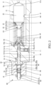
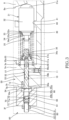
- the piston pump 100 is provided with the shaft 1 that is rotated by the driving source, a cylinder block 2 that is linked to the shaft 1 and rotated together with the shaft 1, and a case 3 that accommodates the cylinder block 2.
- the case 3 is provided with: a case main body 3a having a bottomed tubular shape; a cover 3b that closes an opening end of the case main body 3a and through which the shaft 1 is inserted; and an auxiliary case part 3f that accommodates an auxiliary biasing part 60, which will be described later.
- An interior of the case 3 is communicated with a tank (not shown) through a drain passage (not shown).
- the interior of the case 3 may be communicated with a suction passage (not shown), which will be described later.
- a first end portion 1a of the shaft 1 that is projected outside via an insertion hole 3c of the cover 3b is connected to a motive-power source (not shown) such as an engine, etc.
- the end portion 1a of the shaft 1 is rotatably supported by the insertion hole 3c of the cover 3b via a bearing 4a.
- a second end portion 1b of the shaft 1 is accommodated in a shaft accommodating hole 3d that is provided in a bottom portion of the case main body 3a and is rotatably supported via a bearing 4b.
- the cylinder block 2 has a through hole 2a through which the shaft 1 is penetrated and the cylinder block 2 is spline-connected to the shaft 1 via the through hole 2a. With such a configuration, the cylinder block 2 is rotated together with the rotation of the shaft 1.
- a plurality of cylinders 2b each having an opening portion on one end surface are formed so as to extend in parallel with the shaft 1.
- the plurality of cylinders 2b are formed at predetermined intervals in the circumferential direction of the cylinder block 2.
- the columnar piston 5 that defines a capacity chamber 6 is inserted so as to be freely reciprocatable.
- a tip end side of each piston 5 is projected from the opening portion of the cylinder 2b, and a spherical surface seat 5a is formed on a tip end portion thereof.
- the piston pump 100 is further provided with: shoes 7 that are each freely and rotatably coupled with the spherical surface seat 5a of the piston 5 and that are each in sliding contact with the spherical surface seat 5a; a swash plate 8 that is in sliding contact with the shoes 7 along with the rotation of the cylinder block 2; and a valve plate 9 that is provided between the cylinder block 2 and the bottom portion of the case main body 3a.
- Each of the shoes 7 is provided with a receiving portion 7a that receives the spherical surface seat 5a that is formed on the tip end of each piston 5 and a circular flat plate portion 7b that is in sliding contact with a sliding contact surface 8a of the swash plate 8.
- An inner surface of the receiving portion 7a is formed to have a spherical surface shape and comes into sliding contact with an outer surface of the received spherical surface seat 5a. With such a configuration, the shoes 7 can undergo angular displacement in any directions with respect to the spherical surface seats 5a.
- the swash plate 8 is supported by the cover 3b so as to be tiltable.
- the flat plate portions 7b of the shoes 7 are in surface contact with the sliding contact surface 8a.
- the valve plate 9 is a circular plate member with which a base end surface of the cylinder block 2 comes into sliding contact and is fixed to the bottom portion of the case main body 3a. Although an illustration is omitted, the valve plate 9 is formed with a suction port that connects the suction passage formed in the cylinder block 2 with the capacity chambers 6 and a discharge port that connects a discharge passage formed in the cylinder block 2 with the capacity chambers 6.
- the piston pump 100 is further provided with: a first biasing part 20 that tilts the swash plate 8 in the direction in which the tilting angle is decreased in response to the fluid pressure supplied; a second biasing part 30 that biases the swash plate 8 in the direction in which the tilting angle is increased against the biasing force exerted by the first biasing part 20; and a regulator 50 that controls the fluid pressure to be guided to the first biasing part 20 in accordance with the tilting angle of the swash plate 8.
- the first biasing part 20 has a control piston 22 that is slidably inserted into a piston accommodating hole 21 formed in the cover 3b and that comes into contact with the swash plate 8 and a control pressure chamber 23 that is defined by the control piston 22 in the piston accommodating hole 21.
- control pressure The fluid pressure (hereinafter, referred to as the "control pressure") adjusted by the regulator 50 is guided to the control pressure chamber 23.
- the control piston 22 biases the swash plate 8 in the direction in which the tilting angle is decreased by the control pressure guided to the control pressure chamber 23.
- the second biasing part 30 is a support spring serving as a supporting biasing member.
- the second biasing part 30 is also referred to as a "support spring 30".
- the support spring 30 is a coil spring and supports the swash plate 8 by exerting the biasing force against the biasing force exerted by the first biasing part 20.
- a first end of the support spring 30 is seated on a first spring seat 31 and a second end thereof is seated on the bottom portion of the case main body 3a.
- the support spring 30 is provided between the first spring seat 31 and the case main body 3a in a compressed state.
- the bottom portion of the case main body 3a is formed with an annular support groove 3e in which the second end portion of the support spring 30 is seated, thereby supporting the second end portion. Therefore, the support spring 30 is configured so as not to exert the biasing force against a control spool 52, which will be described later.
- the first spring seat 31 is a substantially columnar member, and has: a columnar-shaped sliding portion 32; a first boss portion 33 that has a smaller outer diameter than the sliding portion 32 and that projects out from the sliding portion 32 in the axial direction; a second boss portion 34 that has a smaller outer diameter than the first boss portion 33 and that projects out from the first boss portion 33 in the axial direction; and a third boss portion 35 that has a smaller outer diameter than the second boss portion 34 and that projects out from the second boss portion 34 in the axial direction.
- the first end of the support spring 30 is seated on the first spring seat 31 by utilizing a stepped surface 32a formed by an outer diameter difference between the sliding portion 32 and the first boss portion 33 as a seating surface.
- the first spring seat 31 is moved in accordance with the tilting of the swash plate 8 by the biasing force exerted by the support spring 30, an outer spring 51a, which will be described later, and an inner spring 51b.
- the first spring seat 31 is provided with a contacting portion 31a that is formed to have a substantially spherical surface shape and that comes into contact with the swash plate 8.
- the sliding portion 32 of the first spring seat 31 is slidably inserted into a guide hole 41 that is formed in a guide wall part 40 provided on an inner circumference of the case main body 3a.
- the guide hole 41 is formed in the guide wall part 40 such that its center axis extends in parallel with the center axis of the shaft 1 and extends in parallel with or in coaxial with (in coaxial in this embodiment) the center axis of the control spool 52, which will be described later.
- the first spring seat 31 As the sliding portion 32 of the first spring seat 31 slides relative to the guide hole 41, the first spring seat 31 is guided along in the center axial direction of the guide hole 41. With such a configuration, the biasing force exerted by the support spring 30 (and the outer spring 51a and the inner spring 51b, which will be described later) is applied to the swash plate 8 via the first spring seat 31 along the axial direction of the guide hole 41. In other words, the first spring seat 31 is moved so as to follow the tilting of the swash plate 8, and thereby, the support spring 30 (and the outer spring 51a and the inner spring 51b, which will be described later) is extended and compressed. As described above, the first spring seat 31 also functions as a feedback pin that transmits the tilting of the swash plate 8 to the regulator 50.
- the first spring seat 31 may be formed into separate bodies by separately forming a portion on which the support spring 30, the outer spring 51a, and the inner spring 51b are seated and a portion that is guided by the guide hole 41 and comes into contact with the swash plate 8.
- control piston 22 of the first biasing part 20 is provided on the opposite side of the first spring seat 31 so that the swash plate 8 is positioned therebetween.
- control piston 22 and the first spring seat 31 are arranged such that their positions in the circumferential direction with respect to the center axis of the shaft 1 substantially coincide with each other.
- the regulator 50 controls the horsepower (the output) of the piston pump 100 by adjusting the control pressure to be guided to the control pressure chamber 23 of the first biasing part 20 in response to the load of the driving source driving the piston pump 100. More specifically, when the load of the driving source is changed, the discharge pressure from the piston pump 100 is also changed. Thus, in this embodiment, the regulator 50 executes the horsepower control in response to the load of the driving source by adjusting the control pressure in response to the self pressure of the piston pump 100.
- the regulator 50 has: the outer spring 51a and the inner spring 51b each serving as the biasing member that biases the swash plate 8 via the first spring seat 31; the control spool 52 that adjusts the control pressure by being moved in response to the biasing force exerted by the outer spring 51a and the inner spring 51b; and the auxiliary biasing part 60 that exerts the biasing force to the control spool 52 against the biasing force exerted to the control spool 52 by the outer spring 51a and the inner spring 51b.
- the outer spring 51a and the inner spring 51b are each a coil spring and are extended and compressed so as to follow the tilting of the swash plate 8.
- the inner spring 51b has a smaller coiling diameter than the outer spring 51a and is provided on the inner side of the outer spring 51a.
- the outer spring 51a has a smaller coiling diameter than the support spring 30 and is provided on the inner side of the support spring 30.
- the outer spring 51a and the inner spring 51b are both provided on the inner side of the support spring 30.
- First end portions of the outer spring 51a and the inner spring 51b are seated on the first spring seat 31.
- the outer spring 51a is seated on the first spring seat 31 by utilizing a stepped surface 33a, which is formed by an outer diameter difference between the first boss portion 33 of the first spring seat 31 and the second boss portion 34, as the seating surface.
- the inner spring 51b can be seated on the first spring seat 31 by utilizing a stepped surface 34a, which is formed by an outer diameter difference between the second boss portion 34 of the first spring seat 31 and the third boss portion 35, as the seating surface.
- the third boss portion 35 is inserted into the inner side of the inner spring 51b so as to support an inner circumference of the inner spring 51b.
- Second end portions of the outer spring 51a and the inner spring 51b are seated on an end surface of the control spool 52 via a second spring seat 36.
- the second spring seat 36 is moved together with the control spool 52.
- the second spring seat 36 is formed to have the outer diameter that is smaller than the inner diameter of the support spring 30 and is provided on the inner side of the support spring 30. As described above, the second end portion of the support spring 30 is not seated on the second spring seat 36, but is seated in the support groove 3e in the bottom portion of the case main body 3a. Thus, the first end portion of the support spring 30 that is seated on the first spring seat 31 is moved so as to follow the tilting of the swash plate 8, and the second end portion thereof that is seated on the support groove 3e is not moved so as to follow the tilting of the swash plate 8. In other words, the second end portion of the support spring 30 is configured such that the movement thereof is not caused due to the tilting of the swash plate 8.
- the second spring seat 36 is in a floating state in which the second spring seat 36 is not in contact with the bottom portion of the case main body 3a and is separated away from the bottom portion of the case main body 3a.
- the natural length (the free length) of the outer spring 51a is longer than the natural length of the inner spring 51b.
- the inner spring 51b is in the floated state (the state in which the inner spring 51b has the natural length), in which either of the end portions thereof is separated away from the spring seat (the first spring seat 31 in FIG. 1 ).
- the tilting angle of the swash plate 8 is decreased from the maximum state, only the outer spring 51a is compressed at the beginning.
- the support spring 30 and the outer spring 51a/the inner spring 51b are provided adjacent to each other and in parallel with respect to the swash plate 8. More specifically, the outer spring 51a and the inner spring 51b are provided on the inner side in the radial direction of the support spring 30. Furthermore, a configuration in which the biasing force exerted by the support spring 30 and the biasing force exerted by the outer spring 51a and the inner spring 51b are applied in parallel with respect to the swash plate 8 is achieved.
- the case main body 3a is formed with a spool accommodating hole 50a into which the control spool 52 is slidably inserted.
- the spool accommodating hole 50a opens at an end surface 3g of the case main body 3a.
- the opening of the spool accommodating hole 50a to the end surface 3g of the case main body 3a is closed by the auxiliary case part 3f having the bottomed tubular shape that is attached to the end surface 3g of the case main body 3a.
- the case main body 3a is formed with a discharge pressure passage 10 to which the discharge pressure from the piston pump 100 is guided and a control pressure passage 11 that guides the control pressure to the control pressure chamber 23 of the control piston 22.
- the discharge pressure from the piston pump 100 is always guided to the discharge pressure passage 10.
- the control pressure passage 11 communicates with the control pressure chamber 23 through a cover-side passage (not shown) formed in the cover 3b.
- a line that guides the discharge pressure from the piston pump 100 to the discharge pressure passage 10 and a signal pressure passage 12, which will be described later, is schematically shown by a broken line.
- the control spool 52 has: a main body portion 53 that slides with an inner circumferential surface of the spool accommodating hole 50a; a flange portion 54 that is provided on a first end portion of the main body portion 53 and is formed to have a larger outer diameter than the main body portion 53; and a projecting portion 55 that is provided on a second end portion of the main body portion 53 on the opposite side from the flange portion 54 and is inserted into the second spring seat 36.
- the flange portion 54 projects out from the spool accommodating hole 50a to the outside of the case main body 3a and is accommodated in the auxiliary case part 3f.
- the projecting portion 55 is formed to have a smaller outer diameter than the main body portion 53 and a stepped surface 55a, which is formed by an outer diameter difference between the main body portion 53 and the projecting portion 55, comes into contact with the second spring seat 36.
- a first control port 56a and a second control port 56b are each formed in an outer circumference of the control spool 52 as an annular groove.
- a control passage 57 that communicates with the first control port 56a is formed in the control spool 52 so as to penetrate through the control spool 52 in the radial direction.
- the control spool 52 is formed with an axial passage 58 that is provided so as to extend along in the axial direction from the first end portion (the projecting portion 55). Through the axial passage 58, the control passage 57 is communicated with a connection passage 36a that is formed in the second spring seat 36 and opens to the interior of the case main body 3a.
- control passage 57 communicates with the interior of the case 3 via the axial passage 58 and the connection passage 36a of the second spring seat 36.
- the pressure in the control passage 57 is equalized to a tank pressure.
- the auxiliary biasing part 60 has: an auxiliary spring 61 serving as an auxiliary biasing member; a first seating portion 70 on which an end portion of the auxiliary spring 61 is seated; an accommodating chamber 65 that is formed in the auxiliary case part 3f and accommodates the auxiliary spring 61; and an adjusting mechanism 80 that adjusts the biasing force exerted by the auxiliary spring 61.
- the accommodating chamber 65 is formed by an accommodating concave portion 66 that is formed in the auxiliary case part 3f.
- the accommodating concave portion 66 is formed as a concave portion having bottomed tubular shape that opens at an end surface (attachment surface) 3h of the auxiliary case part 3f that is attached to the end surface 3g of the case main body 3a. In other words, the opening of the accommodating concave portion 66 is closed by the end surface 3g of the case main body 3a.
- the accommodating concave portion 66 has: a first concave portion 66a that opens at the attachment surface 3h of the auxiliary case part 3f; a second concave portion 66b that communicates with the first concave portion 66a and has a smaller inner diameter than the first concave portion 66a; and a stepped surface 66c that is formed by an inner diameter difference between the first concave portion 66a and the second concave portion 66b.
- the first concave portion 66a and the second concave portion 66b each has a circular cross-section that is formed coaxially with the spool accommodating hole 50a.
- the flange portion 54 of the control spool 52 is accommodated in the first concave portion 66a.
- the control spool 52 can move in the direction towards the swash plate 8 against the biasing force exerted by the outer spring 51a and the inner spring 51b (towards the right in FIG. 2 ) until the flange portion 54 comes into contact with the end surface 3g of the case main body 3a.
- the end surface 3g of the case main body 3a functions as a stopper portion and the flange portion 54 comes into contact with the end surface 3g of the case main body 3a in response to the movement of the control spool 52, and thereby, further movement of the control spool 52 towards the swash plate 8 is restricted (see FIG. 3 ).
- control spool 52 can move in the direction away from the swash plate 8 by being biased by the outer spring 51a and the inner spring 51b (towards the left in FIG. 2 ) until the flange portion 54 comes into contact with the stepped surface 66c of the accommodating concave portion 66 in the auxiliary case part 3f.
- the flange portion 54 of the control spool 52 is in contact with the stepped surface 66c of the auxiliary case part 3f.
- the inner diameter of the first concave portion 66a of the accommodating concave portion 66 is larger than the inner diameter of the flange portion 54, and the inner diameter of the second concave portion 66b is smaller than the inner diameter of the flange portion 54.
- the auxiliary spring 61 is a coil spring, and is provided between the first seating portion 70 and an end surface of the flange portion 54 of the control spool 52 in a compressed state. In other words, the auxiliary spring 61 comes into direct contact with and exerts the biasing force to the control spool 52.
- the auxiliary spring 61 is provided so as to exert the biasing force in the direction along the moving direction of the control spool 52.
- the end surface of the flange portion 54, on which the auxiliary spring 61 is seated, is formed with a communication passage 54a both ends of which open at an outer circumferential surface of the flange portion 54.
- the communication passage 54a is a slit that is formed to extend in the radial direction of the flange portion 54.
- the communication passage is not limited to the slit provided in the end surface of the flange portion 54.
- the slit may be formed in the stepped surface 66c of the accommodating concave portion 66.
- a through hole penetrating through the flange portion 54 in the axial direction may be utilized as the communication passage, or a passage that is formed over the main body portion 53 and the flange portion 54 of the control spool 52 may also be utilized as the communication passage.
- the communication passage is provided in at least one of the auxiliary case part 3f and the control spool 52 such that the first concave portion 66a and the second concave portion 66b are communicated in a state in which the flange portion 54 is in contact with the stepped surface 66c.
- the first seating portion 70 is accommodated in the second concave portion 66b of the accommodating concave portion 66.
- the first seating portion 70 has a circular plate portion 71 that is provided with a seating surface 71a, on which a first end of the auxiliary spring 61 is seated, and a projecting portion 72 that projects out from the seating surface 71a of the circular plate portion 71 and supports the auxiliary spring 61 from the inner side.
- a seal member (not shown) is provided on an outer circumference of the circular plate portion 71 to seal a gap between the outer circumference of the circular plate portion 71 and an inner circumference of the second concave portion 66b.
- the adjusting mechanism 80 has: an internal thread hole 81 that is formed in the bottom portion of the auxiliary case part 3f; a screw member 82 that is threaded to the internal thread hole 81 and moves the first seating portion 70 back and forth in the biasing direction of the auxiliary spring 61; and a nut 83 that fixes the threaded position of the screw member 82 with respect to the internal thread hole 81.
- the internal thread hole 81 penetrates the bottom portion of the auxiliary case part 3f and opens to the second concave portion 66b.
- the screw member 82 comes into contact with the first seating portion 70 from the other side in the axial direction from the side on which the auxiliary spring 61 is seated.
- the screw member 82 is moved back and forth with respect to the first seating portion 70 along in the axial direction (along the direction of the biasing force exerted by the auxiliary spring 61).
- the auxiliary spring 61 is configured such that the biasing force exerted by the auxiliary spring 61 can be adjusted.
- the nut 83 is threaded to the screw member 82 and tightened against the auxiliary case part 3f, the threaded position of the screw member 82 with respect to the internal thread hole 81 is fixed.
- the biasing force exerted by the auxiliary spring 61 (the set load) be adjusted within a range not exceeding the resultant force of the biasing force exerted by the outer spring 51a and the inner spring 51b.
- the control spool 52 is prevented from undergoing unintentional movement due to compression of the outer spring 51a and the inner spring 51b during the adjustment of the biasing force exerted by the auxiliary spring 61.
- the case main body 3a is formed with the signal pressure passage 12 that guides a signal pressure to the accommodating chamber 65.
- the signal pressure passage 12 is formed to open at the end surface 3g of the case main body 3a so as to oppose to the first concave portion 66a of the accommodating concave portion 66.
- the discharge pressure (the self pressure) of the piston pump 100 is guided to the accommodating chamber 65.
- a thrust force caused by the signal pressure acts on the control spool 52.
- the direction of the thrust force caused by the signal pressure acting on the control spool 52 is the same as the direction of the biasing force exerted by the auxiliary spring 61, in other words, it is the direction in which the control spool 52 is moved so as to compress the outer spring 51a and the inner spring 51b.
- the accommodating chamber 65 accommodates the auxiliary spring 61 and also functions as a signal pressure chamber that exerts the thrust force to the control spool 52 by the signal pressure guided thereto.
- the signal pressure passage 12 is preferably configured so as not to be closed by the flange portion 54 that comes into contact with the end surface 3g of the case main body 3a.
- the signal pressure passage 12 may be configured so as to open at the end surface 3g of the case main body 3a at the position radially outside of the flange portion 54.
- a slit extending in the radial direction may be formed in a flange surface of the flange portion 54 that comes into contact with the end surface 3g of the case main body 3a, or a passage that penetrates through the flange portion 54 in the axial direction may be formed, and thereby, a configuration in which the signal pressure passage 12 and the first concave portion 66a are communicated through such a slit or passage may be achieved.
- the signal pressure passage 12 may be formed in the auxiliary case part 3f so as to open to the first concave portion 66a or the second concave portion 66b. As described above, in this embodiment, the degree of design freedom of the position for forming the signal pressure passage 12 is improved.
- the signal pressure passage 12 As in this embodiment, by forming the signal pressure passage 12 so as to open at the end surface of the case main body 3a and not forming the signal pressure passage 12 in the auxiliary case part 3f, it is not necessary to secure a space for forming the signal pressure passage 12 in the auxiliary case part 3f. Therefore, it is possible to reduce the size of the auxiliary case part 3f.
- control spool 52 is biased in the direction away from the swash plate 8 (towards the left in the figure) by the biasing force exerted by the outer spring 51a and the inner spring 51b.
- control spool 52 is biased in the direction approaching the swash plate 8 by the biasing force exerted by the auxiliary spring 61 and the thrust force exerted by the discharge pressure from the piston pump 100 (the signal pressure) guided to the accommodating chamber 65.
- the control spool 52 is moved such that the biasing force exerted by the outer spring 51a and the inner spring 51b, the biasing force exerted by the auxiliary spring 61, and the biasing force caused by the discharge pressure from the piston pump 100 are balanced.
- FIGs. 1 and 2 show a state in which the control spool 52 is positioned at the second position.
- the position of the control spool 52 is switched from the second position shown in FIGs. 1 and 2 to the first position shown in FIG. 3 as the control spool 52 is moved to the right direction in the figure.
- the first position is a position at which the tilting angle of the swash plate 8 is decreased to reduce the discharge capacity of the piston pump 100.
- the second position is a position at which the tilting angle of the swash plate 8 is increased to increase the discharge capacity of the piston pump 100.
- the horsepower control is performed such that the discharge capacity of the piston pump 100 (the tilting angle of the swash plate 8) is controlled so as to maintain the discharge pressure from the piston pump 100 constant by the regulator 50.
- the control spool 52 of the regulator 50 is biased so as to be positioned at the first position by the biasing force exerted by the auxiliary spring 61 and the biasing force exerted by the discharge pressure from the piston pump 100 guided to the accommodating chamber 65.
- the control spool 52 is biased so as to be positioned at the second position by the biasing force exerted by the outer spring 51a and the inner spring 51b.
- the control spool 52 of the regulator 50 is positioned at the second position, and the tilting angle of the swash plate 8 is maintained at the maximum angle (see FIG. 1 ).
- the discharge pressure from the piston pump 100 is increased as the load of the hydraulic cylinder driven by the discharge pressure from the piston pump 100 is increased.
- the discharge pressure from the piston pump 100 is increased in the state in which the tilting angle of the swash plate 8 is maintained at the maximum angle, the resultant force of the discharge pressure and the biasing force exerted by the auxiliary spring 61 comes to exceed the biasing force exerted by the outer spring 51a.
- the control spool 52 is moved in the direction in which the position of the control spool 52 is switched from the second position to the first position (the right direction in the figure).
- the control spool 52 when the control spool 52 is moved to the first position, the discharge pressure is guided to the control pressure passage 11 from the discharge pressure passage 10, and therefore, the control pressure is increased. More specifically, as the control spool 52 is moving toward the first position, an opening area (a flow passage area) of the second control port 56b of the control spool 52 to the control pressure passage 11 is increased. Thus, as a moving amount of the control spool 52 in the direction in which the position of the control spool 52 is switched to the first position (the right direction in the figure) is increased, the control pressure guided to the control pressure passage 11 is increased. As the control pressure guided to the control pressure passage 11 is increased, the control piston 22 (see FIG. 1 ) is moved toward the swash plate 8, and the swash plate 8 is tilted in the direction in which the tilting angle is decreased. Thus, the discharge capacity of the piston pump 100 is reduced.
- the first spring seat 31 is moved in the left direction in the figure by following the swash plate 8 so as to compress the outer spring 51a and the inner spring 51b.
- the first spring seat 31 is moved so as to bias the control spool 52 via the outer spring 51a (and the inner spring 51b) in the direction in which the position of the control spool 52 is switched to the second position.
- the control pressure supplied to the control pressure chamber 23 through the control pressure passage 11 is decreased.
- the control pressure is decreased, when the biasing force imparted to the swash plate 8 by the control pressure is balanced with the biasing force imparted to the swash plate 8 by the outer spring 51a (and the inner spring 51b), the movement of the control piston 22 (the tilting of the swash plate 8) is stopped.
- the discharge pressure from the piston pump 100 is increased, the discharge capacity is reduced.
- the discharge pressure from the piston pump 100 is decreased as the load of the hydraulic cylinder driven by the discharge pressure from the piston pump 100 is decreased.
- the discharge pressure from the piston pump 100 is decreased, the resultant force of the discharge pressure from the piston pump 100 and the biasing force acting on the control spool 52 by the auxiliary spring 61 comes to fall below the biasing force exerted by the outer spring 51a and the inner spring 51b.
- the control spool 52 is moved in the direction in which the position of the control spool 52 is switched from the first position to the second position.
- the control pressure passage 11 is communicated with the control passage 57 under the tank pressure, the control pressure is decreased.
- the swash plate 8 is tilted in the direction in which the tilting angle is increased by the first spring seat 31 that receives the biasing force exerted by the outer spring 51a and the inner spring 51b.
- the first spring seat 31 receiving the biasing force exerted by the outer spring 51a and the inner spring 51b is moved in the right direction in the figure by following the swash plate 8 such that the outer spring 51a and the inner spring 51b are extended.
- the biasing force received by the control spool 52 from the outer spring 51a and the inner spring 51b is decreased. Therefore, the control spool 52 is moved in the direction in which the outer spring 51a and the inner spring 51b are compressed by receiving the discharge pressure guided to the accommodating chamber 65 and the biasing force exerted by the auxiliary spring 61.
- control spool 52 is moved in the direction in which the position of the control spool 52 is switched from the second position to the first position so as to follow the first spring seat 31.
- the control spool 52 is positioned at the first position again and the control pressure is increased, and the biasing force imparted to the swash plate 8 by the control pressure is balanced with the biasing force imparted to the swash plate 8 by the outer spring 51a (and the inner spring 51b), then the movement of the control piston 22 (the tilting of the swash plate 8) is stopped.
- the discharge pressure from the piston pump 100 is decreased, the discharge capacity is increased.
- the horsepower control is performed such that the discharge capacity of the piston pump 100 is reduced as the discharge pressure from the piston pump 100 is increased, and such that the discharge capacity is increased as the discharge pressure is decreased.
- the control spool 52 adjusts the control pressure by moving such that the biasing force exerted by the discharge pressure (the self pressure) of the piston pump 100, the biasing force exerted by the outer spring 51a and the inner spring 51b, and the biasing force exerted by the auxiliary spring 61 are balanced.
- the horsepower control is performed for the piston pump 100.
- the characteristics of the horsepower control by the regulator 50 are influenced by the biasing force exerted by the outer spring 51a and the inner spring 51b, the biasing force exerted by the auxiliary spring 61, and the biasing force exerted by the self pressure.
- by providing a plurality of configurations to bias the control spool 52 it is possible to improve the degree of design freedom for realizing diverse control characteristics, and so, it is possible to realize the desired control characteristics with a higher accuracy.
- the accommodating chamber 65 accommodates the auxiliary spring 61 and also functions as the signal pressure chamber that exerts the thrust force to the control spool 52 by the signal pressure guided thereto. Therefore, compared with a case in which the signal pressure chamber is provided separately from the accommodating chamber 65, it is possible to reduce the size of the device configuration. Thus, with the piston pump 100, it is possible to realize the diverse control characteristics by the regulator 50, while suppressing an increase in the device size.
- the auxiliary case part 3f is attached by attaching the end surface 3h, at which the accommodating concave portion 66 opens, to the end surface 3g of the case main body 3a. Therefore, the signal pressure passage 12 can be formed in the case main body 3a, and there is no need to form the signal pressure passage 12 in the auxiliary case part 3f. Thus, it is possible to reduce the size of the auxiliary case part 3f.
- the signal pressure passage 12 may be formed over the case main body 3a and the auxiliary case part 3f so as to open to the first concave portion 66a or the second concave portion 66b defining the accommodating chamber 65. As described above, according to the piston pump 100, because it is possible to arbitrarily set how the signal pressure passage 12 is to be connected to the accommodating chamber 65, the degree of design freedom is improved.
- the opening of the accommodating concave portion 66 in the auxiliary case part 3f is configured to be closed by the end surface 3g of the case main body 3a, there is no need to provide a separate cap, plug, or the like to seal the opening of the accommodating concave portion 66, and so, it is possible to reduce the number of parts.
- the control spool 52 slides in the spool accommodating hole 50a with a predetermined sliding clearance therebetween. Therefore, in the above-described first embodiment, there is a possibility that a flow of the working oil is caused between the accommodating chamber 65 and the discharge pressure passage 10 through the sliding clearance. Especially when there is a pressure difference between the accommodating chamber 65 and the discharge pressure passage 10, the flow of the working oil through the sliding clearance is likely to be caused.
- a drain chamber 13 for discharging the working oil may be formed.
- the drain chamber 13 is connected to a tank, for example.
- the drain chamber 13 is formed to have an annular shape in an inner circumference of the spool accommodating hole 50a on the side of the opening of the spool accommodating hole 50a (the left side in FIG. 4 ) from the discharge pressure passage 10 in the axial direction of the control spool 52.
- a piston pump 200 according to a second embodiment of the present invention will be described with reference to FIGs. 5 and 6 .
- differences from the above-described first embodiment will be mainly described, and components that are the same as those in the above-described first embodiment are assigned the same reference numerals and descriptions thereof will be omitted.
- the auxiliary spring 61 comes into direct contact with the flange portion 54 of the control spool 52 and exerts the biasing force to the control spool 52.
- an auxiliary biasing part 160 further has: a transmission pin 63 serving as a transmission part that transmits the biasing force exerted by the auxiliary spring 61 to the control spool 52; and a second seating portion (seating portion) 75 on which the end portion of the auxiliary spring 61 is seated.
- the biasing force exerted by the auxiliary spring 61 is exerted to the control spool 52 via the transmission pin 63.
- the spool accommodating hole 50a opens at the end surface 3g of the case main body 3a via an end portion concave portion 50b.
- the end portion concave portion 50b is a circular hole having a larger inner diameter than the spool accommodating hole 50a.
- a stepped surface 50c is formed by an inner diameter difference between the spool accommodating hole 50a and the end portion concave portion 50b.
- the flange portion 54 of the control spool 52 is accommodated in the end portion concave portion 50b. As the flange portion 54 comes into contact with the stepped surface 50c, further movement of the control spool 52 towards the swash plate 8 is restricted. In other words, in the second embodiment, the stepped surface 50c functions as the stopper portion.
- auxiliary case part 3f having a bottomed tubular shape.
- an end surface 3i on the bottom portion side which is on the opposite side from the end surface at which the accommodating concave portion 66 opens, is attached to the end surface 3g of the case main body 3a.
- the accommodating concave portion 66 in the auxiliary case part 3f opens on the opposite side from the end surface 3i of the auxiliary case part 3f that is attached to the case main body 3a.
- the accommodating concave portion 66 is formed as a circular hole having a uniform inner diameter along the axial direction.
- the accommodating concave portion 66 is formed coaxially with the spool accommodating hole 50a.
- the opening of the accommodating concave portion 66 is sealed by a cap 90, on an outer circumference of which an O-ring (not shown) serving as a sealing member is attached.
- the second seating portion 75 is movably accommodated in the accommodating chamber 65 together with the auxiliary spring 61.
- the second seating portion 75 is moved in the accommodating chamber 65 in response to the movement of the control spool 52 and in response to the extension and compression of the auxiliary spring 61.
- the second seating portion 75 has a circular plate portion 76 that is provided with a seating surface 76a, on which a second end of the auxiliary spring 61 is seated, and a projecting portion 77 that projects out from the seating surface 76a of the circular plate portion 76 and supports the auxiliary spring 61 from the inner side.
- the outer diameter of the circular plate portion 76 of the second seating portion 75 is smaller than the inner diameter of the accommodating concave portion 66 in the auxiliary case part 3f.
- a gap is formed in the radial direction (in other words, in the direction perpendicular to the moving direction of the control spool 52) between an outer circumference of the second seating portion 75 and the inner wall of the accommodating chamber 65 (an inner circumferential surface of the accommodating concave portion 66).
- the transmission pin 63 is provided between the second seating portion 75 and the control spool 52 and is slidably inserted into a pin hole 65b that is formed in the bottom portion of the accommodating concave portion 66 in the auxiliary case part 3f.
- the pin hole 65b is formed coaxially with the accommodating concave portion 66, and a first end of the pin hole 65b opens to the accommodating concave portion 66.
- a second end of the pin hole 65b opens at the end surface of the auxiliary case part 3f that opposes to the end surface of the case main body 3a.
- the transmission pin 63 is a substantially columnar member and has, on both ends thereof, a pair of contact portions 63a and 63b, each of which is formed to have a spherical surface shape.
- the first contact portion 63a comes into contact with the second seating portion 75 with the spherical outer surface.
- the second contact portion 63b comes into contact with the end surface of the flange portion 54 of the control spool 52 with the spherical outer surface.
- the force transmitted from the auxiliary spring 61 by the second seating portion 75 and the transmission pin 63 acts on the flange portion 54 of the control spool 52.
- FIG. 7 is an enlarged schematic diagram of a contacting part in a state in which the circular plate portion 76 of the second seating portion 75 in a tilted state is in contact with the first contact portion 63a of the transmission pin 63.
- a broken line shows a transmission pin 163, as a comparative example, that does not have the contact portion 63a and has an end portion formed to have a flat surface perpendicular to the center axis and the second seating portion 75 that is in contact with the transmission pin 163.
- the transmission pin 63 of the present embodiment and the transmission pin 163 of the comparative example are illustrated such that their positions in the axial direction (the positions of the end portions) are at the same position.
- the contact portion with the circular plate portion 76 is not the outer circumference portion as in the comparative example, and the transmission pin 63 comes to contact with the circular plate portion 76 at the radially inward spherical surface portion. Therefore, for example, as shown in FIG.
- a distance L1 from the reference point P0 to a contact point P1 between the transmission pin 63 of this embodiment and the circular plate portion 76 is shorter than a distance L2 from the reference point P0 to a contact point P2 between the transmission pin 163 of the comparative example and the circular plate portion 76 (L1 ⁇ L2).
- the force acting around the reference point P0 is smaller for the transmission pin 63 of this embodiment than that in the comparative example.
- the number of the transmission pin 63 is not limited to one, and a plurality of the transmission pins 63 may be provided.
- a plurality of the transmission pins 63 may be provided.
- the accommodating chamber 65 accommodates the auxiliary spring 61 and also functions as the signal pressure chamber that exerts the thrust force to the control spool 52 by the signal pressure guided thereto. Therefore, it is possible to realize the diverse control characteristics by the regulator 50, while suppressing an increase in the device size.
- the biasing force caused by the signal pressure in the accommodating chamber 65 is exerted to the control spool 52 in accordance with the cross-sectional area (the pressure receiving area) of the transmission pin 63.
- the biasing force caused by the signal pressure in the accommodating chamber 65 can be adjusted by the cross-sectional area of the transmission pin 63, the degree of freedom for design is improved, and it becomes easier to exhibit the diverse control characteristics by the regulator 50.
- the signal pressure guided into the accommodating chamber 65 relatively high and making the cross-sectional area of the transmission pin 63 relatively small it is possible to exert sufficient biasing force by the pressure in the accommodating chamber 65 while preventing the increase in the size of the piston pump 200.
- a gap is formed between an outer circumference of the second seating portion 75 of the regulator 50 and the inner wall of the accommodating chamber 65.
- the second seating portion is tilted relative to the moving direction of the control spool due to formation of a gap between the outer circumference of the second seating portion and the inner wall of the accommodating chamber.
- the frictional force between the transmission pin and the auxiliary case part is increased due to the tilting of the transmission pin in the pin hole, and the direction of the force transmitted from the transmission pin to the control spool is deflected with respect to the moving direction of the control spool.
- the transmission pin 63 comes into contact with the second seating portion 75 and the control spool 52 respectively at the contact portions 63a and 63b each having the spherical surface shape. Therefore, even if the second seating portion 75 is tilted in the accommodating chamber 65, the second seating portion 75 is tilted along the spherical surface of the contact portion 63a with respect to the transmission pin 63, and so, it is possible to relatively suppress the force with which the transmission pin 63 is pressed against the pin hole 65b.
- the force transmitted from the transmission pin 63 acts on the flange portion 54.
- the flange portion 54 has a larger outer diameter and a larger cross-sectional area than the main body portion 53 of the control spool 52, and so, it is easy to secure the pressure receiving area. Therefore, it becomes easier to increase the diameter of the transmission pin 63 and/or to provide a plurality of transmission pins 63, and so, it is easy to secure the thrust force caused by the signal pressure by increasing the pressure receiving area for the signal pressure.
- the part where the sliding is caused due to the signal pressure in the accommodating chamber 65 is present only at one location between the transmission pin 63 and the pin hole 65b, it is possible to relatively suppress a leakage of the working oil from the accommodating chamber 65.
- a piston pump 300 according to a third embodiment of the present invention will be described with reference to FIG. 8 .
- differences from the above-described second embodiment will be mainly described, and components that are the same as those in the above-described second embodiment are assigned the same reference numerals and descriptions thereof will be omitted.
- the configuration of an auxiliary biasing part 260 differs from the configuration of the auxiliary biasing part 160 in the second embodiment, and other configurations are the same.
- the auxiliary biasing part 260 is provided with a pair of transmission pins 63.
- the auxiliary biasing part 260 further has: a signal pressure chamber 67 to which a second signal pressure, which is different from the signal pressure guided to the accommodating chamber 65, is guided; and a second transmission pin 68 serving as a thrust force transmission part that transmits the thrust force, which is exerted by the second signal pressure guided to the signal pressure chamber 67, to the control spool 52.
- the pair of transmission pins 63 are provided on the positions that are symmetrical relative to the center axis of the control spool 52.
- the auxiliary case part 3f is formed with the pin holes 65b correspondingly to the positions of the pair of transmission pins 63.
- the end surface of the auxiliary case part 3f opposing to the case main body 3a is formed with an insert hole 65c for forming the signal pressure chamber 67.
- the second transmission pin 68 is slidably inserted into the insert hole 65c.
- the insert hole 65c is a bottomed circular hole, and the signal pressure chamber 67 is formed between the bottom portion of the insert hole 65c and an end portion of the second transmission pin 68.
- the insert hole 65c is formed coaxially with the spool accommodating hole 50a and faces the end portion concave portion 50b of the spool accommodating hole 50a.
- the length of the second transmission pin 68 in the axial direction is shorter than the depth of the insert hole 65c (the dimension along the axial direction).
- the signal pressure passage 12 that guides the signal pressure to the signal pressure chamber 67 is formed in the auxiliary case part 3f.
- the signal pressure guided to the accommodating chamber 65 is an external pump pressure that is discharged from, together with the piston pump 300, other hydraulic pump driven by a motive-power source
- the second signal pressure guided to the signal pressure chamber 67 is the discharge pressure (the self pressure) of the piston pump 300.
- the thrust force based on the second signal pressure acts on the control spool 52 via the second transmission pin 68.
- control spool 52 is biased by the biasing force exerted by the outer spring 51a and the inner spring 51b in the direction away from the swash plate 8 (the left direction in the figure).
- control spool 52 is biased in the direction approaching the swash plate 8 by the biasing force exerted by the auxiliary spring 61, the thrust force caused by the external pump pressure (the signal pressure) guided to the accommodating chamber 65, and the thrust force caused by the discharge pressure (the second signal pressure) of the piston pump 100 guided to a second signal pressure chamber.
- control spool 52 is moved such that the biasing force exerted by the outer spring 51a and the inner spring 51b, the biasing force exerted by the auxiliary spring 61, the biasing force caused by the discharge pressure of the piston pump 300, and the biasing force caused by the external pump pressure are balanced.
- the control spool 52 is biased towards the swash plate 8 also by the external pump pressure.
- the self pressure at which the horsepower control is executed is smaller than that in the second embodiment by the magnitude of the external pump pressure.
- the degree of design freedom of the horsepower control characteristics is improved.
- the number of the transmission pins 63 is not limited to a pair, and a single pin or three or more pins may be provided.
- the number of the second transmission pin 68 is also not limited to one, and a plurality of pins may be provided.
- the self pressure may be guided to the accommodating chamber 65, and the external pump pressure may be guided to the signal pressure chamber 67.
- the signal pressure guided to the accommodating chamber 65 and the second signal pressure guided to the signal pressure chamber 67 are not limited those described in the above-described embodiment, and other pressures may also be utilized.
- the second signal pressure to be guided to the signal pressure chamber 67 may also be the self pressure or the external pump pressure that has been regulated by a solenoid valve.
- a piston pump 400 according to a fourth embodiment of the present invention will be described with reference to FIG. 9 .
- differences from the above-described first embodiment will be mainly described, and components that are the same as those in the above-described first embodiment are assigned the same reference numerals and descriptions thereof will be omitted.
- the regulator 50 performs the horsepower control in which the control pressure is controlled in response to the load of the driving source driving the piston pump 100. Specifically, the self pressure of the piston pump 100 is directly guided to the accommodating chamber 65 of the regulator 50 as the signal pressure.
- the pressure generated by regulating the pressure from a hydraulic pressure source 103, such as a gear pump, etc. for example, by an electromagnetic proportional pressure reducing valve 101 is guided to the regulator 50 as the signal pressure.
- an opening degree is adjusted by an electric signal output from a controller 102 in response to an operation performed by an operator.
- the tilting angle control of the swash plate 8 can be performed by the electric signal, it is possible to realize any control characteristics in response to the operation performed by the operator.
- the piston pump 400 according to the fourth embodiment is not intended for the horsepower control, and the piston pump according to the present invention is not limited to those for performing the horsepower control.
- the biasing member is preferably configured of a single spring 51c.
- the biasing member is preferably configured of a single spring 51c.
- the piston pump 400 is provided with a high-pressure selection valve 104 that select a higher pressure between the pressure supplied from the hydraulic pressure source 103 and the self pressure of the piston pump 400 and guides the selected higher pressure to the discharge pressure passage 10.
- a high-pressure selection valve 104 that selects a higher pressure between the pressure supplied from the hydraulic pressure source 103 and the self pressure of the piston pump 400 and guides the selected higher pressure to the discharge pressure passage 10.
- the high-pressure selection valve 104 may not be provided, and the pressure from the hydraulic pressure source 103, such as the self pressure of the piston pump 400, the gear pump, or the like, may be independently guided to the discharge pressure passage 10.
- the hydraulic pressure source 103 and the high-pressure selection valve 104 may also be applied to the first to third embodiments as described above.
- the horsepower control may be performed for the fourth embodiment, in which the signal pressure is generated by the electromagnetic proportional pressure reducing valve 101.
- the horsepower control can be performed by adjusting the opening degree of the electromagnetic proportional pressure reducing valve 101 in response to the load of the driving source of the piston pump 400, generating the signal pressure by lowering the pressure of the hydraulic pressure source 103 or the self pressure, and guiding the signal pressure to the accommodating chamber 65.
- the controller 102 may calculate the load of the driving source from engine torque, engine speed, or the like, generate the signal pressure by adjusting the opening degree of the electromagnetic proportional pressure reducing valve 101 on the basis of the load, and guide the signal pressure to the accommodating chamber 65.
- the controller 102 may calculate the load of the driving source from torque or speed of the electric motor, generate the signal pressure by adjusting the opening degree of the electromagnetic proportional pressure reducing valve 101 on the basis of the load, and guide the signal pressure to the accommodating chamber 65.
- the signal pressure is generated by adjusting the opening degree of the electromagnetic proportional pressure reducing valve 101 in response to the load of the driving source, it becomes possible to control the horsepower control electrically.
- the signal pressure is generated by the electromagnetic proportional pressure reducing valve 101
- the tilting angle of the swash plate 8 is controlled by the electromagnetic proportional pressure reducing valve 101 instead of the horsepower control.
- the signal pressure generated by the electromagnetic proportional pressure reducing valve 101 on the basis of the load of the driving source may also be utilized.
- the piston pump 100, 200, 300, 400 includes: the cylinder block 2 configured to be rotated together with the shaft 1; the plurality of cylinders 2b formed in the cylinder block 2, the cylinders 2b being arranged at predetermined intervals in the circumferential direction of the shaft 1; the pistons 5 respectively slidably inserted into the cylinders 2b, the pistons 5 being configured to each define the capacity chamber 6 in the interior of each of the cylinders 2b; the tiltable swash plate 8 configured to cause each of the pistons 5 to reciprocate such that the capacity chamber 6 is expanded and contracted; the first biasing part 20 configured to bias the swash plate 8 in accordance with the supplied control pressure; the second biasing part 30 configured to bias the swash plate 8 against the first biasing part 20; and the regulator 50 configured to control the control pressure guided to the first biasing part 20, wherein the regulator 50 has: the biasing member (the outer spring 51a and the inner spring 51b) configured to be extended and compressed by following the tilting of the swash plate 8; the
- the accommodating chamber 65 functions not only to accommodate the auxiliary biasing member, but also as the pressure chamber for exerting the thrust force in accordance with the signal pressure, it is possible to achieve the size reduction compared with a case in which the accommodating chamber 65 and the pressure chamber are provided separately.
- the auxiliary biasing member comes into direct contact with the control spool 52 and exerts the biasing force to the control spool 52.
- the regulator 50 further has: the seating portion (the second seating portion 75) on which the first end of the auxiliary biasing member is seated, the seating portion being provided in the accommodating chamber 65 so as to be movable along the moving direction of the control spool 52; and the transmission part (the transmission pin 63) provided between the seating portion and the control spool 52, the transmission part being configured to transmit the biasing force exerted by the auxiliary biasing member to the control spool 52.
- the biasing force caused by the signal pressure in the accommodating chamber 65 is exerted to the control spool 52 in accordance with the cross-sectional area (the pressure receiving area) of the transmission part.
- the biasing force caused by the signal pressure in the accommodating chamber 65 can be adjusted by the cross-sectional area of the transmission part, the degree of freedom for design is improved, and it becomes easier to exhibit the diverse control characteristics by the regulator 50.
- the seating portion is provided such that the gap is formed between the seating portion and the inner wall of the accommodating chamber 65 in the direction perpendicular to the moving direction of the control spool 52.
- the transmission part has the contact portion 63a formed to have the spherical surface shape, the contact portion 63a being configured to come into contact with the seating portion.
- the auxiliary biasing part 260 is further provided with: the signal pressure chamber 67 to which the second signal pressure, which is different from the signal pressure guided to the accommodating chamber 65, is guided; and the thrust force transmission part (the second transmission pin 68) that transmits the thrust force, which is exerted by the second signal pressure guided to the signal pressure chamber 67, to the control spool 52.
- the piston pump 100, 200, 300, 400 has the case 3 provided with the spool accommodating hole 50a into which the control spool 52 is inserted, wherein the control spool 52 has: the main body portion 53 configured to slides in the spool accommodating hole 50a; and the flange portion 54 provided on the end portion of the main body portion 53, the flange portion 54 having a larger outer diameter than the main body portion 53, and the control spool 52 is configured such that, as the flange portion 54 comes into contact with the stopper portion formed in the case 3 (the end surface 3g of the case main body 3a, the stepped surface 50c) in response to the movement of the control spool 52, the further movement of the control spool 52 along the biasing force exerted by the auxiliary biasing member is restricted, and the biasing force exerted by the auxiliary biasing member and the thrust force caused by the signal pressure act on the flange portion 54.
- the control spool 52 has: the main body portion 53 configured to slides in the spool accommodating hole
- the flange portion 54 having a larger cross-sectional area in a relative manner is provided on the end portion of the main body portion 53.
- the signal pressure is generated by the electromagnetic proportional pressure reducing valve 101.
- the flange portion 54 of the control spool 52 is accommodated in the first concave portion 66a of the accommodating concave portion 66 in the auxiliary case part 3f, and the end surface 3g of the case main body 3a functions as the stopper portion that restricts the movement of the control spool 52.
- the flange portion 54 is accommodated in the end portion concave portion 50b of the case main body 3a, and the stepped surface 50c between the end portion concave portion 50b and the spool accommodating hole 50a functions as the stopper portion.
- the end portion concave portion 50b and the stepped surface 50c may be provided in the case main body 3a.
- the concave portion may be provided in the end surface opposing to the case main body 3a to accommodate the flange portion 54.
- the concave portion for accommodating the flange portion 54 and the stopper portion with which the flange portion 54 comes into contact in the case 3 they may be provided in the case main body 3a, or they may be provided in the auxiliary case part 3f.
- the concave portion for accommodating the flange portion 54 may be provided in both of the case main body 3a and the auxiliary case part 3f.
- the transmission pin 63 and the second transmission pin 68 respectively have the contact portions 63a and 63b and the contact portion 68a each having the spherical surface shape.
- the configuration with the contact portion 63a, 63b, 68a having the spherical surface shape is not essential, and the transmission pin 63 and the second transmission pin 68 may come into, at the flat surface, surface contact with the second seating portion 75/the flange portion 54 of the control spool 52.
- the gap is formed between the outer circumference of the second seating portion 75 and the inner wall of the accommodating chamber 65 (the inner circumference of the accommodating concave portion 66).
- the second seating portion 75 may slide on the inner circumference of the accommodating concave portion 66.
- the accommodating chamber 65 is divided into two chambers by the second seating portion 75. The same hydraulic pressure may be guided to these two chambers with each other by achieving the mutual communication through a communication hole formed in the second seating portion 75 or by guiding the signal pressure from the signal pressure passage 12 to the respective chambers.
- different signal pressures may be guided to the two chambers partitioned in the accommodating chamber 65 by the second seating portion 75.
- the pressure in the chamber which is defined between the second seating portion 75 and the bottom portion of the accommodating concave portion 66, among the two chambers (the chamber in which the transmission pin 63 is accommodated) may be set to be relatively lower than the pressure in the other chamber.
Landscapes
- Engineering & Computer Science (AREA)
- Mechanical Engineering (AREA)
- General Engineering & Computer Science (AREA)
- Reciprocating Pumps (AREA)
Abstract
Description
- The present invention relates to a fluid pressure rotating machine.
-
JP2008-240518A - The horsepower control regulator includes a control spring that presses a feedback pin, which is to be displaced by following the swash plate, toward the swash plate side and a control spool that controls hydraulic pressure to be guided to a pressure chamber of the large-diameter piston. A hydraulic pressure such as a discharge pressure and signal pressure acts on the control spool, and the control spool is moved such that the force received due to the hydraulic pressure and the force received due to the control spring are balanced.
- In the horsepower control regulator disclosed by
JP2008-240518A - To achieve diverse control characteristics in such a regulator, it is conceivable to provide a plurality of configurations that exert force on the control spool, thereby increasing the degree of design freedom. However, when the plurality of configurations for biasing the control spool are provided, it results in an increase in the size of the fluid pressure rotating machine.
- An object of the present invention is to provide a fluid pressure rotating machine with which the degree of freedom for control characteristics by a regulator can be improved while suppressing an increase in size.
- According to one aspect of the present invention, a fluid pressure rotating machine includes: a cylinder block configured to be rotated together with a driving shaft; a plurality of cylinders formed in the cylinder block, the cylinders being arranged at predetermined intervals in a circumferential direction of the driving shaft; pistons respectively slidably inserted into the cylinders, the pistons being configured to each define a capacity chamber in an interior of each of the cylinders; a tiltable swash plate configured to cause each of the pistons to reciprocate such that the capacity chamber is expanded and contracted; a first biasing part configured to bias the swash plate in accordance with supplied control pressure; a second biasing part configured to bias the swash plate against the first biasing part; and a regulator configured to control the control pressure guided to the first biasing part, wherein the regulator has: a biasing member configured to be extended and compressed by following tilting of the swash plate; a control spool configured to adjust the control pressure by being moved in response to biasing force exerted by the biasing member; an auxiliary biasing member configured to exert biasing force to the control spool against the biasing force exerted by the biasing member; and an accommodating chamber configured to accommodate the auxiliary biasing member, and a signal pressure is guided to the accommodating chamber, the signal pressure exerting a thrust force to the control spool against the biasing force exerted by the biasing member.
-
- [
FIG. 1] FIG. 1 is a sectional diagram of a fluid pressure rotating machine according to a first embodiment of the present invention. - [
FIG. 2] FIG. 2 is a diagram showing a configuration of a regulator of the fluid pressure rotating machine according to the first embodiment of the present invention and is an enlarged sectional diagram of a portion A inFIG. 1 . - [
FIG. 3] FIG. 3 is a diagram showing a state in which a control spool has moved from the state shown inFIG. 2 and is in contact with a case main body. - [
FIG. 4] FIG. 4 is a sectional diagram showing a modification of the fluid pressure rotating machine according to the first embodiment of the present invention and is a diagram corresponding toFIG. 2 . - [
FIG. 5] FIG. 5 is a sectional diagram showing the configuration of the regulator of the fluid pressure rotating machine according to a second embodiment of the present invention. - [
FIG. 6] FIG. 6 is a diagram showing the configuration of the regulator of the fluid pressure rotating machine according to the second embodiment of the present invention and is an enlarged sectional diagram of a portion B inFIG. 2 . - [
FIG. 7] FIG. 7 is a diagram for explaining action of a transmission pin in the second embodiment of the present invention, and is an enlarged diagram of a contacting part between the transmission pin and a second seating portion. - [
FIG. 8] FIG. 8 is an enlarged sectional diagram showing the configuration of the regulator of the fluid pressure rotating machine according to a third embodiment of the present invention. - [
FIG. 9] FIG. 9 is a sectional diagram of the fluid pressure rotating machine according to a fourth embodiment of the present invention. - In the following, a fluid
pressure rotating machine 100 according to a first embodiment of the present invention will be described with reference to the drawings. - The fluid
pressure rotating machine 100 functions as a piston pump capable of supplying working oil serving as working fluid by causingpistons 5 to reciprocate by rotating a shaft (driving shaft) 1 by a motive force from an external driving source. In addition, the fluidpressure rotating machine 100 functions as a piston motor capable of outputting a rotationally driving force by rotating theshaft 1 by causing thepistons 5 to reciprocate by a fluid pressure of the working oil that is supplied externally. In the above, the fluidpressure rotating machine 100 may function only as the piston pump or only as the piston motor. The driving source for driving the fluidpressure rotating machine 100 includes, for example, an engine or an electric motor. - In the following description, a case in which the fluid
pressure rotating machine 100 is used as the piston pump will be illustrated, and the fluidpressure rotating machine 100 is referred to as a "piston pump 100". - The
piston pump 100 is used as a hydraulic pressure source that supplies the working oil to an actuator (not shown) for driving a driving target, such as a hydraulic cylinder, etc., for example. As shown inFIG. 1 , thepiston pump 100 is provided with theshaft 1 that is rotated by the driving source, acylinder block 2 that is linked to theshaft 1 and rotated together with theshaft 1, and acase 3 that accommodates thecylinder block 2. - The
case 3 is provided with: a casemain body 3a having a bottomed tubular shape; acover 3b that closes an opening end of the casemain body 3a and through which theshaft 1 is inserted; and anauxiliary case part 3f that accommodates anauxiliary biasing part 60, which will be described later. An interior of thecase 3 is communicated with a tank (not shown) through a drain passage (not shown). The interior of thecase 3 may be communicated with a suction passage (not shown), which will be described later. - A
first end portion 1a of theshaft 1 that is projected outside via aninsertion hole 3c of thecover 3b is connected to a motive-power source (not shown) such as an engine, etc. Theend portion 1a of theshaft 1 is rotatably supported by theinsertion hole 3c of thecover 3b via abearing 4a. Asecond end portion 1b of theshaft 1 is accommodated in a shaft accommodatinghole 3d that is provided in a bottom portion of the casemain body 3a and is rotatably supported via abearing 4b. Although an illustration is omitted, a rotation shaft (not shown) of another hydraulic pump (not shown), such as a gear pump, etc., which is driven together with thepiston pump 100 by the motive-power source, is connected to thesecond end portion 1b of theshaft 1 coaxially so as to be rotated together with theshaft 1. - The
cylinder block 2 has a throughhole 2a through which theshaft 1 is penetrated and thecylinder block 2 is spline-connected to theshaft 1 via the throughhole 2a. With such a configuration, thecylinder block 2 is rotated together with the rotation of theshaft 1. - In the
cylinder block 2, a plurality ofcylinders 2b each having an opening portion on one end surface are formed so as to extend in parallel with theshaft 1. The plurality ofcylinders 2b are formed at predetermined intervals in the circumferential direction of thecylinder block 2. In each of thecylinders 2b, thecolumnar piston 5 that defines acapacity chamber 6 is inserted so as to be freely reciprocatable. A tip end side of eachpiston 5 is projected from the opening portion of thecylinder 2b, and aspherical surface seat 5a is formed on a tip end portion thereof. - The
piston pump 100 is further provided with:shoes 7 that are each freely and rotatably coupled with thespherical surface seat 5a of thepiston 5 and that are each in sliding contact with thespherical surface seat 5a; aswash plate 8 that is in sliding contact with theshoes 7 along with the rotation of thecylinder block 2; and avalve plate 9 that is provided between thecylinder block 2 and the bottom portion of the casemain body 3a. - Each of the
shoes 7 is provided with a receivingportion 7a that receives thespherical surface seat 5a that is formed on the tip end of eachpiston 5 and a circularflat plate portion 7b that is in sliding contact with a slidingcontact surface 8a of theswash plate 8. An inner surface of the receivingportion 7a is formed to have a spherical surface shape and comes into sliding contact with an outer surface of the receivedspherical surface seat 5a. With such a configuration, theshoes 7 can undergo angular displacement in any directions with respect to thespherical surface seats 5a. - In order to make a discharge amount of the
piston pump 100 variable, theswash plate 8 is supported by thecover 3b so as to be tiltable. Theflat plate portions 7b of theshoes 7 are in surface contact with the slidingcontact surface 8a. - The
valve plate 9 is a circular plate member with which a base end surface of thecylinder block 2 comes into sliding contact and is fixed to the bottom portion of the casemain body 3a. Although an illustration is omitted, thevalve plate 9 is formed with a suction port that connects the suction passage formed in thecylinder block 2 with thecapacity chambers 6 and a discharge port that connects a discharge passage formed in thecylinder block 2 with thecapacity chambers 6. - The
piston pump 100 is further provided with: afirst biasing part 20 that tilts theswash plate 8 in the direction in which the tilting angle is decreased in response to the fluid pressure supplied; asecond biasing part 30 that biases theswash plate 8 in the direction in which the tilting angle is increased against the biasing force exerted by thefirst biasing part 20; and aregulator 50 that controls the fluid pressure to be guided to thefirst biasing part 20 in accordance with the tilting angle of theswash plate 8. - As shown in
FIG. 1 , thefirst biasing part 20 has acontrol piston 22 that is slidably inserted into apiston accommodating hole 21 formed in thecover 3b and that comes into contact with theswash plate 8 and acontrol pressure chamber 23 that is defined by thecontrol piston 22 in thepiston accommodating hole 21. - The fluid pressure (hereinafter, referred to as the "control pressure") adjusted by the
regulator 50 is guided to thecontrol pressure chamber 23. Thecontrol piston 22 biases theswash plate 8 in the direction in which the tilting angle is decreased by the control pressure guided to thecontrol pressure chamber 23. - The second biasing
part 30 is a support spring serving as a supporting biasing member. In the following, thesecond biasing part 30 is also referred to as a "support spring 30". Thesupport spring 30 is a coil spring and supports theswash plate 8 by exerting the biasing force against the biasing force exerted by thefirst biasing part 20. - As shown in
FIG. 2 , a first end of thesupport spring 30 is seated on afirst spring seat 31 and a second end thereof is seated on the bottom portion of the casemain body 3a. Thesupport spring 30 is provided between thefirst spring seat 31 and the casemain body 3a in a compressed state. The bottom portion of the casemain body 3a is formed with an annular support groove 3e in which the second end portion of thesupport spring 30 is seated, thereby supporting the second end portion. Therefore, thesupport spring 30 is configured so as not to exert the biasing force against acontrol spool 52, which will be described later. - The
first spring seat 31 is a substantially columnar member, and has: a columnar-shaped sliding portion 32; a first boss portion 33 that has a smaller outer diameter than the sliding portion 32 and that projects out from the sliding portion 32 in the axial direction; asecond boss portion 34 that has a smaller outer diameter than the first boss portion 33 and that projects out from the first boss portion 33 in the axial direction; and a third boss portion 35 that has a smaller outer diameter than thesecond boss portion 34 and that projects out from thesecond boss portion 34 in the axial direction. - The first end of the
support spring 30 is seated on thefirst spring seat 31 by utilizing a stepped surface 32a formed by an outer diameter difference between the sliding portion 32 and the first boss portion 33 as a seating surface. Thefirst spring seat 31 is moved in accordance with the tilting of theswash plate 8 by the biasing force exerted by thesupport spring 30, an outer spring 51a, which will be described later, and an inner spring 51b. - The
first spring seat 31 is provided with a contacting portion 31a that is formed to have a substantially spherical surface shape and that comes into contact with theswash plate 8. The sliding portion 32 of thefirst spring seat 31 is slidably inserted into aguide hole 41 that is formed in aguide wall part 40 provided on an inner circumference of the casemain body 3a. Theguide hole 41 is formed in theguide wall part 40 such that its center axis extends in parallel with the center axis of theshaft 1 and extends in parallel with or in coaxial with (in coaxial in this embodiment) the center axis of thecontrol spool 52, which will be described later. - As the sliding portion 32 of the
first spring seat 31 slides relative to theguide hole 41, thefirst spring seat 31 is guided along in the center axial direction of theguide hole 41. With such a configuration, the biasing force exerted by the support spring 30 (and the outer spring 51a and the inner spring 51b, which will be described later) is applied to theswash plate 8 via thefirst spring seat 31 along the axial direction of theguide hole 41. In other words, thefirst spring seat 31 is moved so as to follow the tilting of theswash plate 8, and thereby, the support spring 30 (and the outer spring 51a and the inner spring 51b, which will be described later) is extended and compressed. As described above, thefirst spring seat 31 also functions as a feedback pin that transmits the tilting of theswash plate 8 to theregulator 50. - The
first spring seat 31 may be formed into separate bodies by separately forming a portion on which thesupport spring 30, the outer spring 51a, and the inner spring 51b are seated and a portion that is guided by theguide hole 41 and comes into contact with theswash plate 8. - As shown in
FIG. 1 , thecontrol piston 22 of the first biasingpart 20 is provided on the opposite side of thefirst spring seat 31 so that theswash plate 8 is positioned therebetween. In other words, thecontrol piston 22 and thefirst spring seat 31 are arranged such that their positions in the circumferential direction with respect to the center axis of theshaft 1 substantially coincide with each other. - The
regulator 50 controls the horsepower (the output) of thepiston pump 100 by adjusting the control pressure to be guided to thecontrol pressure chamber 23 of the first biasingpart 20 in response to the load of the driving source driving thepiston pump 100. More specifically, when the load of the driving source is changed, the discharge pressure from thepiston pump 100 is also changed. Thus, in this embodiment, theregulator 50 executes the horsepower control in response to the load of the driving source by adjusting the control pressure in response to the self pressure of thepiston pump 100. - The
regulator 50 has: the outer spring 51a and the inner spring 51b each serving as the biasing member that biases theswash plate 8 via thefirst spring seat 31; thecontrol spool 52 that adjusts the control pressure by being moved in response to the biasing force exerted by the outer spring 51a and the inner spring 51b; and theauxiliary biasing part 60 that exerts the biasing force to thecontrol spool 52 against the biasing force exerted to thecontrol spool 52 by the outer spring 51a and the inner spring 51b. - The outer spring 51a and the inner spring 51b are each a coil spring and are extended and compressed so as to follow the tilting of the
swash plate 8. The inner spring 51b has a smaller coiling diameter than the outer spring 51a and is provided on the inner side of the outer spring 51a. In addition, the outer spring 51a has a smaller coiling diameter than thesupport spring 30 and is provided on the inner side of thesupport spring 30. In other words, the outer spring 51a and the inner spring 51b are both provided on the inner side of thesupport spring 30. - First end portions of the outer spring 51a and the inner spring 51b are seated on the
first spring seat 31. Specifically, as shown inFIG. 2 , the outer spring 51a is seated on thefirst spring seat 31 by utilizing a stepped surface 33a, which is formed by an outer diameter difference between the first boss portion 33 of thefirst spring seat 31 and thesecond boss portion 34, as the seating surface. The inner spring 51b can be seated on thefirst spring seat 31 by utilizing a stepped surface 34a, which is formed by an outer diameter difference between thesecond boss portion 34 of thefirst spring seat 31 and the third boss portion 35, as the seating surface. The third boss portion 35 is inserted into the inner side of the inner spring 51b so as to support an inner circumference of the inner spring 51b. - Second end portions of the outer spring 51a and the inner spring 51b are seated on an end surface of the
control spool 52 via asecond spring seat 36. Thesecond spring seat 36 is moved together with thecontrol spool 52. - The
second spring seat 36 is formed to have the outer diameter that is smaller than the inner diameter of thesupport spring 30 and is provided on the inner side of thesupport spring 30. As described above, the second end portion of thesupport spring 30 is not seated on thesecond spring seat 36, but is seated in the support groove 3e in the bottom portion of the casemain body 3a. Thus, the first end portion of thesupport spring 30 that is seated on thefirst spring seat 31 is moved so as to follow the tilting of theswash plate 8, and the second end portion thereof that is seated on the support groove 3e is not moved so as to follow the tilting of theswash plate 8. In other words, the second end portion of thesupport spring 30 is configured such that the movement thereof is not caused due to the tilting of theswash plate 8. - In a state in which the tilting angle of the
swash plate 8 is maximized (the state shown inFIG. 1 ), thesecond spring seat 36 is in a floating state in which thesecond spring seat 36 is not in contact with the bottom portion of the casemain body 3a and is separated away from the bottom portion of the casemain body 3a. - The natural length (the free length) of the outer spring 51a is longer than the natural length of the inner spring 51b. In a state in which the tilting angle of the
swash plate 8 is maximized (the state shown inFIG. 1 ), while the outer spring 51a is in the compressed state between thefirst spring seat 31 and thesecond spring seat 36, the inner spring 51b is in the floated state (the state in which the inner spring 51b has the natural length), in which either of the end portions thereof is separated away from the spring seat (thefirst spring seat 31 inFIG. 1 ). In other words, when the tilting angle of theswash plate 8 is decreased from the maximum state, only the outer spring 51a is compressed at the beginning. Once the outer spring 51a is compressed to the point at which the length of the outer spring 51a becomes shorter than the natural length of the inner spring 51b, both of the outer spring 51a and the inner spring 51b are compressed. Thus, a configuration in which an elastic force exerted by the outer spring 51a and the inner spring 51b and applied to theswash plate 8 via thefirst spring seat 31 is increased stepwise is achieved. - As described above, the
support spring 30 and the outer spring 51a/the inner spring 51b are provided adjacent to each other and in parallel with respect to theswash plate 8. More specifically, the outer spring 51a and the inner spring 51b are provided on the inner side in the radial direction of thesupport spring 30. Furthermore, a configuration in which the biasing force exerted by thesupport spring 30 and the biasing force exerted by the outer spring 51a and the inner spring 51b are applied in parallel with respect to theswash plate 8 is achieved. - The case
main body 3a is formed with a spoolaccommodating hole 50a into which thecontrol spool 52 is slidably inserted. The spoolaccommodating hole 50a opens at anend surface 3g of the casemain body 3a. The opening of the spoolaccommodating hole 50a to theend surface 3g of the casemain body 3a is closed by theauxiliary case part 3f having the bottomed tubular shape that is attached to theend surface 3g of the casemain body 3a. - In addition, the case
main body 3a is formed with adischarge pressure passage 10 to which the discharge pressure from thepiston pump 100 is guided and acontrol pressure passage 11 that guides the control pressure to thecontrol pressure chamber 23 of thecontrol piston 22. The discharge pressure from thepiston pump 100 is always guided to thedischarge pressure passage 10. Thecontrol pressure passage 11 communicates with thecontrol pressure chamber 23 through a cover-side passage (not shown) formed in thecover 3b. InFIG. 1 , a line that guides the discharge pressure from thepiston pump 100 to thedischarge pressure passage 10 and asignal pressure passage 12, which will be described later, is schematically shown by a broken line. - As shown in
FIG. 2 , thecontrol spool 52 has: amain body portion 53 that slides with an inner circumferential surface of the spoolaccommodating hole 50a; aflange portion 54 that is provided on a first end portion of themain body portion 53 and is formed to have a larger outer diameter than themain body portion 53; and a projecting portion 55 that is provided on a second end portion of themain body portion 53 on the opposite side from theflange portion 54 and is inserted into thesecond spring seat 36. - The
flange portion 54 projects out from the spoolaccommodating hole 50a to the outside of the casemain body 3a and is accommodated in theauxiliary case part 3f. The projecting portion 55 is formed to have a smaller outer diameter than themain body portion 53 and a stepped surface 55a, which is formed by an outer diameter difference between themain body portion 53 and the projecting portion 55, comes into contact with thesecond spring seat 36. - A first control port 56a and a second control port 56b are each formed in an outer circumference of the
control spool 52 as an annular groove. In addition, a control passage 57 that communicates with the first control port 56a is formed in thecontrol spool 52 so as to penetrate through thecontrol spool 52 in the radial direction. Furthermore, thecontrol spool 52 is formed with an axial passage 58 that is provided so as to extend along in the axial direction from the first end portion (the projecting portion 55). Through the axial passage 58, the control passage 57 is communicated with a connection passage 36a that is formed in thesecond spring seat 36 and opens to the interior of the casemain body 3a. - As described above, the control passage 57 communicates with the interior of the
case 3 via the axial passage 58 and the connection passage 36a of thesecond spring seat 36. Thus, the pressure in the control passage 57 is equalized to a tank pressure. - The
auxiliary biasing part 60 has: anauxiliary spring 61 serving as an auxiliary biasing member; afirst seating portion 70 on which an end portion of theauxiliary spring 61 is seated; anaccommodating chamber 65 that is formed in theauxiliary case part 3f and accommodates theauxiliary spring 61; and anadjusting mechanism 80 that adjusts the biasing force exerted by theauxiliary spring 61. - The
accommodating chamber 65 is formed by an accommodatingconcave portion 66 that is formed in theauxiliary case part 3f. The accommodatingconcave portion 66 is formed as a concave portion having bottomed tubular shape that opens at an end surface (attachment surface) 3h of theauxiliary case part 3f that is attached to theend surface 3g of the casemain body 3a. In other words, the opening of the accommodatingconcave portion 66 is closed by theend surface 3g of the casemain body 3a. - The accommodating
concave portion 66 has: a first concave portion 66a that opens at the attachment surface 3h of theauxiliary case part 3f; a second concave portion 66b that communicates with the first concave portion 66a and has a smaller inner diameter than the first concave portion 66a; and a stepped surface 66c that is formed by an inner diameter difference between the first concave portion 66a and the second concave portion 66b. The first concave portion 66a and the second concave portion 66b each has a circular cross-section that is formed coaxially with the spoolaccommodating hole 50a. - The
flange portion 54 of thecontrol spool 52 is accommodated in the first concave portion 66a. Thecontrol spool 52 can move in the direction towards theswash plate 8 against the biasing force exerted by the outer spring 51a and the inner spring 51b (towards the right inFIG. 2 ) until theflange portion 54 comes into contact with theend surface 3g of the casemain body 3a. In other words, theend surface 3g of the casemain body 3a functions as a stopper portion and theflange portion 54 comes into contact with theend surface 3g of the casemain body 3a in response to the movement of thecontrol spool 52, and thereby, further movement of thecontrol spool 52 towards theswash plate 8 is restricted (seeFIG. 3 ). - In addition, the
control spool 52 can move in the direction away from theswash plate 8 by being biased by the outer spring 51a and the inner spring 51b (towards the left inFIG. 2 ) until theflange portion 54 comes into contact with the stepped surface 66c of the accommodatingconcave portion 66 in theauxiliary case part 3f. In a state in which the tilting angle of theswash plate 8 is maximum as shown inFIGs. 1 and2 , theflange portion 54 of thecontrol spool 52 is in contact with the stepped surface 66c of theauxiliary case part 3f. In other words, the inner diameter of the first concave portion 66a of the accommodatingconcave portion 66 is larger than the inner diameter of theflange portion 54, and the inner diameter of the second concave portion 66b is smaller than the inner diameter of theflange portion 54. - The
auxiliary spring 61 is a coil spring, and is provided between thefirst seating portion 70 and an end surface of theflange portion 54 of thecontrol spool 52 in a compressed state. In other words, theauxiliary spring 61 comes into direct contact with and exerts the biasing force to thecontrol spool 52. Theauxiliary spring 61 is provided so as to exert the biasing force in the direction along the moving direction of thecontrol spool 52. - The end surface of the
flange portion 54, on which theauxiliary spring 61 is seated, is formed with a communication passage 54a both ends of which open at an outer circumferential surface of theflange portion 54. The communication passage 54a is a slit that is formed to extend in the radial direction of theflange portion 54. With such a configuration, even in a state in which theflange portion 54 is in contact with the stepped surface 66c, an interior of the first concave portion 66a and an interior the second concave portion 66b are communicated through the communication passage 54a. Thus, the accommodating chamber 65 (the accommodating concave portion 66) is prevented from being divided into two chambers by the contact of theflange portion 54 with the stepped surface 66c. - The communication passage is not limited to the slit provided in the end surface of the
flange portion 54. For example, the slit may be formed in the stepped surface 66c of the accommodatingconcave portion 66. In addition, a through hole penetrating through theflange portion 54 in the axial direction may be utilized as the communication passage, or a passage that is formed over themain body portion 53 and theflange portion 54 of thecontrol spool 52 may also be utilized as the communication passage. As described above, it suffices that the communication passage is provided in at least one of theauxiliary case part 3f and thecontrol spool 52 such that the first concave portion 66a and the second concave portion 66b are communicated in a state in which theflange portion 54 is in contact with the stepped surface 66c. - The
first seating portion 70 is accommodated in the second concave portion 66b of the accommodatingconcave portion 66. Thefirst seating portion 70 has acircular plate portion 71 that is provided with aseating surface 71a, on which a first end of theauxiliary spring 61 is seated, and a projectingportion 72 that projects out from theseating surface 71a of thecircular plate portion 71 and supports theauxiliary spring 61 from the inner side. A seal member (not shown) is provided on an outer circumference of thecircular plate portion 71 to seal a gap between the outer circumference of thecircular plate portion 71 and an inner circumference of the second concave portion 66b. - As shown in
FIG. 2 , the adjustingmechanism 80 has: aninternal thread hole 81 that is formed in the bottom portion of theauxiliary case part 3f; ascrew member 82 that is threaded to theinternal thread hole 81 and moves thefirst seating portion 70 back and forth in the biasing direction of theauxiliary spring 61; and anut 83 that fixes the threaded position of thescrew member 82 with respect to theinternal thread hole 81. - The
internal thread hole 81 penetrates the bottom portion of theauxiliary case part 3f and opens to the second concave portion 66b. Thescrew member 82 comes into contact with thefirst seating portion 70 from the other side in the axial direction from the side on which theauxiliary spring 61 is seated. By adjusting the threaded position between thescrew member 82 and theinternal thread hole 81, thescrew member 82 is moved back and forth with respect to thefirst seating portion 70 along in the axial direction (along the direction of the biasing force exerted by the auxiliary spring 61). In other words, by moving thescrew member 82 back and forth, thefirst seating portion 70 is moved back and forth such that theauxiliary spring 61 is extended and compressed, and thereby, it is possible to adjust a set load (an initial load) of theauxiliary spring 61. With such a configuration, theauxiliary spring 61 is configured such that the biasing force exerted by theauxiliary spring 61 can be adjusted. As thenut 83 is threaded to thescrew member 82 and tightened against theauxiliary case part 3f, the threaded position of thescrew member 82 with respect to theinternal thread hole 81 is fixed. - It is preferred that the biasing force exerted by the auxiliary spring 61 (the set load) be adjusted within a range not exceeding the resultant force of the biasing force exerted by the outer spring 51a and the inner spring 51b. By doing so, the
control spool 52 is prevented from undergoing unintentional movement due to compression of the outer spring 51a and the inner spring 51b during the adjustment of the biasing force exerted by theauxiliary spring 61. - In addition, the case
main body 3a is formed with thesignal pressure passage 12 that guides a signal pressure to theaccommodating chamber 65. Thesignal pressure passage 12 is formed to open at theend surface 3g of the casemain body 3a so as to oppose to the first concave portion 66a of the accommodatingconcave portion 66. In this embodiment, as the signal pressure according to the load of the driving source, the discharge pressure (the self pressure) of thepiston pump 100 is guided to theaccommodating chamber 65. By guiding the signal pressure to theaccommodating chamber 65, a thrust force caused by the signal pressure acts on thecontrol spool 52. The direction of the thrust force caused by the signal pressure acting on thecontrol spool 52 is the same as the direction of the biasing force exerted by theauxiliary spring 61, in other words, it is the direction in which thecontrol spool 52 is moved so as to compress the outer spring 51a and the inner spring 51b. As described above, theaccommodating chamber 65 accommodates theauxiliary spring 61 and also functions as a signal pressure chamber that exerts the thrust force to thecontrol spool 52 by the signal pressure guided thereto. - The
signal pressure passage 12 is preferably configured so as not to be closed by theflange portion 54 that comes into contact with theend surface 3g of the casemain body 3a. Specifically, for example, thesignal pressure passage 12 may be configured so as to open at theend surface 3g of the casemain body 3a at the position radially outside of theflange portion 54. In addition, a slit extending in the radial direction may be formed in a flange surface of theflange portion 54 that comes into contact with theend surface 3g of the casemain body 3a, or a passage that penetrates through theflange portion 54 in the axial direction may be formed, and thereby, a configuration in which thesignal pressure passage 12 and the first concave portion 66a are communicated through such a slit or passage may be achieved. - In addition, even in a state in which the
flange portion 54 is in contact with the stepped surface 66c of the accommodatingconcave portion 66, because the first concave portion 66a is not cut off from the second concave portion 66b, thesignal pressure passage 12 may be formed in theauxiliary case part 3f so as to open to the first concave portion 66a or the second concave portion 66b. As described above, in this embodiment, the degree of design freedom of the position for forming thesignal pressure passage 12 is improved. As in this embodiment, by forming thesignal pressure passage 12 so as to open at the end surface of the casemain body 3a and not forming thesignal pressure passage 12 in theauxiliary case part 3f, it is not necessary to secure a space for forming thesignal pressure passage 12 in theauxiliary case part 3f. Therefore, it is possible to reduce the size of theauxiliary case part 3f. - As described above, the
control spool 52 is biased in the direction away from the swash plate 8 (towards the left in the figure) by the biasing force exerted by the outer spring 51a and the inner spring 51b. In addition, thecontrol spool 52 is biased in the direction approaching theswash plate 8 by the biasing force exerted by theauxiliary spring 61 and the thrust force exerted by the discharge pressure from the piston pump 100 (the signal pressure) guided to theaccommodating chamber 65. In other words, thecontrol spool 52 is moved such that the biasing force exerted by the outer spring 51a and the inner spring 51b, the biasing force exerted by theauxiliary spring 61, and the biasing force caused by the discharge pressure from thepiston pump 100 are balanced. - Specifically, the
control spool 52 is moved between two positions, i.e. between a first position and a second position.FIGs. 1 and2 show a state in which thecontrol spool 52 is positioned at the second position. The position of thecontrol spool 52 is switched from the second position shown inFIGs. 1 and2 to the first position shown inFIG. 3 as thecontrol spool 52 is moved to the right direction in the figure. - The first position is a position at which the tilting angle of the
swash plate 8 is decreased to reduce the discharge capacity of thepiston pump 100. When thecontrol spool 52 is positioned at the first position, thedischarge pressure passage 10 and thecontrol pressure passage 11 of the casemain body 3a are communicated through the second control port 56b of thecontrol spool 52, and the communication between the control passage 57 of thecontrol spool 52 and thecontrol pressure passage 11 is shut off. Thus, when thecontrol spool 52 is positioned at the first position, the discharge pressure from thepiston pump 100 is guided to thecontrol pressure chamber 23 of the first biasingpart 20. - The second position is a position at which the tilting angle of the
swash plate 8 is increased to increase the discharge capacity of thepiston pump 100. When thecontrol spool 52 is positioned at the second position, thecontrol pressure passage 11 and the control passage 57 of thecontrol spool 52 are communicated through the first control port 56a, and the communication between thedischarge pressure passage 10 and thecontrol pressure passage 11 is shut off. Thus, when thecontrol spool 52 is positioned at the second position, the tank pressure is guided to thecontrol pressure chamber 23. - Next, operation of the
piston pump 100 will be described. - In the
piston pump 100, the horsepower control is performed such that the discharge capacity of the piston pump 100 (the tilting angle of the swash plate 8) is controlled so as to maintain the discharge pressure from thepiston pump 100 constant by theregulator 50. - The
control spool 52 of theregulator 50 is biased so as to be positioned at the first position by the biasing force exerted by theauxiliary spring 61 and the biasing force exerted by the discharge pressure from thepiston pump 100 guided to theaccommodating chamber 65. In addition, thecontrol spool 52 is biased so as to be positioned at the second position by the biasing force exerted by the outer spring 51a and the inner spring 51b. - In a state in which the biasing force caused by the discharge pressure from the
piston pump 100 and theauxiliary spring 61 is maintained so as to be equal to or lower than the biasing force exerted by the outer spring 51a, thecontrol spool 52 of theregulator 50 is positioned at the second position, and the tilting angle of theswash plate 8 is maintained at the maximum angle (seeFIG. 1 ). - The discharge pressure from the
piston pump 100 is increased as the load of the hydraulic cylinder driven by the discharge pressure from thepiston pump 100 is increased. As the discharge pressure from thepiston pump 100 is increased in the state in which the tilting angle of theswash plate 8 is maintained at the maximum angle, the resultant force of the discharge pressure and the biasing force exerted by theauxiliary spring 61 comes to exceed the biasing force exerted by the outer spring 51a. As a result, thecontrol spool 52 is moved in the direction in which the position of thecontrol spool 52 is switched from the second position to the first position (the right direction in the figure). - As shown in
FIG. 3 , when thecontrol spool 52 is moved to the first position, the discharge pressure is guided to thecontrol pressure passage 11 from thedischarge pressure passage 10, and therefore, the control pressure is increased. More specifically, as thecontrol spool 52 is moving toward the first position, an opening area (a flow passage area) of the second control port 56b of thecontrol spool 52 to thecontrol pressure passage 11 is increased. Thus, as a moving amount of thecontrol spool 52 in the direction in which the position of thecontrol spool 52 is switched to the first position (the right direction in the figure) is increased, the control pressure guided to thecontrol pressure passage 11 is increased. As the control pressure guided to thecontrol pressure passage 11 is increased, the control piston 22 (seeFIG. 1 ) is moved toward theswash plate 8, and theswash plate 8 is tilted in the direction in which the tilting angle is decreased. Thus, the discharge capacity of thepiston pump 100 is reduced. - As the
swash plate 8 is tilted in the direction in which the tilting angle is decreased, thefirst spring seat 31 is moved in the left direction in the figure by following theswash plate 8 so as to compress the outer spring 51a and the inner spring 51b. In other words, as theswash plate 8 is tilted in the direction in which the tilting angle is decreased, thefirst spring seat 31 is moved so as to bias thecontrol spool 52 via the outer spring 51a (and the inner spring 51b) in the direction in which the position of thecontrol spool 52 is switched to the second position. As a result, as thecontrol spool 52 is pushed buck and moved in the direction in which the position of thecontrol spool 52 is switched to the second position, the control pressure supplied to thecontrol pressure chamber 23 through thecontrol pressure passage 11 is decreased. As the control pressure is decreased, when the biasing force imparted to theswash plate 8 by the control pressure is balanced with the biasing force imparted to theswash plate 8 by the outer spring 51a (and the inner spring 51b), the movement of the control piston 22 (the tilting of the swash plate 8) is stopped. As described above, as the discharge pressure from thepiston pump 100 is increased, the discharge capacity is reduced. - Conversely, the discharge pressure from the
piston pump 100 is decreased as the load of the hydraulic cylinder driven by the discharge pressure from thepiston pump 100 is decreased. As the discharge pressure from thepiston pump 100 is decreased, the resultant force of the discharge pressure from thepiston pump 100 and the biasing force acting on thecontrol spool 52 by theauxiliary spring 61 comes to fall below the biasing force exerted by the outer spring 51a and the inner spring 51b. As a result, thecontrol spool 52 is moved in the direction in which the position of thecontrol spool 52 is switched from the first position to the second position. When thecontrol spool 52 is moved to the second position, because thecontrol pressure passage 11 is communicated with the control passage 57 under the tank pressure, the control pressure is decreased. As the control pressure is decreased, theswash plate 8 is tilted in the direction in which the tilting angle is increased by thefirst spring seat 31 that receives the biasing force exerted by the outer spring 51a and the inner spring 51b. - As the
swash plate 8 is tilted in the direction in which the tilting angle is increased, thefirst spring seat 31 receiving the biasing force exerted by the outer spring 51a and the inner spring 51b is moved in the right direction in the figure by following theswash plate 8 such that the outer spring 51a and the inner spring 51b are extended. As a result, the biasing force received by thecontrol spool 52 from the outer spring 51a and the inner spring 51b is decreased. Therefore, thecontrol spool 52 is moved in the direction in which the outer spring 51a and the inner spring 51b are compressed by receiving the discharge pressure guided to theaccommodating chamber 65 and the biasing force exerted by theauxiliary spring 61. In other words, thecontrol spool 52 is moved in the direction in which the position of thecontrol spool 52 is switched from the second position to the first position so as to follow thefirst spring seat 31. When thecontrol spool 52 is positioned at the first position again and the control pressure is increased, and the biasing force imparted to theswash plate 8 by the control pressure is balanced with the biasing force imparted to theswash plate 8 by the outer spring 51a (and the inner spring 51b), then the movement of the control piston 22 (the tilting of the swash plate 8) is stopped. As described above, as the discharge pressure from thepiston pump 100 is decreased, the discharge capacity is increased. - As described above, the horsepower control is performed such that the discharge capacity of the
piston pump 100 is reduced as the discharge pressure from thepiston pump 100 is increased, and such that the discharge capacity is increased as the discharge pressure is decreased. - The
control spool 52 adjusts the control pressure by moving such that the biasing force exerted by the discharge pressure (the self pressure) of thepiston pump 100, the biasing force exerted by the outer spring 51a and the inner spring 51b, and the biasing force exerted by theauxiliary spring 61 are balanced. As a result, the horsepower control is performed for thepiston pump 100. In other words, the characteristics of the horsepower control by theregulator 50 are influenced by the biasing force exerted by the outer spring 51a and the inner spring 51b, the biasing force exerted by theauxiliary spring 61, and the biasing force exerted by the self pressure. As described above, by providing a plurality of configurations to bias thecontrol spool 52, it is possible to improve the degree of design freedom for realizing diverse control characteristics, and so, it is possible to realize the desired control characteristics with a higher accuracy. - According to the embodiment described above, the advantages described below are afforded.
- With the
piston pump 100, because the biasing force exerted by theauxiliary spring 61 and the biasing force (the thrust force) caused by the signal pressure act on thecontrol spool 52, it becomes easier to realize the diverse control characteristics by theregulator 50. In addition, theaccommodating chamber 65 accommodates theauxiliary spring 61 and also functions as the signal pressure chamber that exerts the thrust force to thecontrol spool 52 by the signal pressure guided thereto. Therefore, compared with a case in which the signal pressure chamber is provided separately from theaccommodating chamber 65, it is possible to reduce the size of the device configuration. Thus, with thepiston pump 100, it is possible to realize the diverse control characteristics by theregulator 50, while suppressing an increase in the device size. - In addition, in the
piston pump 100, theauxiliary case part 3f is attached by attaching the end surface 3h, at which the accommodatingconcave portion 66 opens, to theend surface 3g of the casemain body 3a. Therefore, thesignal pressure passage 12 can be formed in the casemain body 3a, and there is no need to form thesignal pressure passage 12 in theauxiliary case part 3f. Thus, it is possible to reduce the size of theauxiliary case part 3f. In addition, thesignal pressure passage 12 may be formed over the casemain body 3a and theauxiliary case part 3f so as to open to the first concave portion 66a or the second concave portion 66b defining theaccommodating chamber 65. As described above, according to thepiston pump 100, because it is possible to arbitrarily set how thesignal pressure passage 12 is to be connected to theaccommodating chamber 65, the degree of design freedom is improved. - In addition, because the opening of the accommodating
concave portion 66 in theauxiliary case part 3f is configured to be closed by theend surface 3g of the casemain body 3a, there is no need to provide a separate cap, plug, or the like to seal the opening of the accommodatingconcave portion 66, and so, it is possible to reduce the number of parts. - Next, a modification of the first embodiment will be described with reference to
FIG. 4 . - The
control spool 52 slides in the spoolaccommodating hole 50a with a predetermined sliding clearance therebetween. Therefore, in the above-described first embodiment, there is a possibility that a flow of the working oil is caused between theaccommodating chamber 65 and thedischarge pressure passage 10 through the sliding clearance. Especially when there is a pressure difference between theaccommodating chamber 65 and thedischarge pressure passage 10, the flow of the working oil through the sliding clearance is likely to be caused. - In the first embodiment, in order to suppress the flow of the working oil between the
accommodating chamber 65 and thedischarge pressure passage 10 through such a sliding clearance, as shown inFIG. 4 , adrain chamber 13 for discharging the working oil may be formed. Thedrain chamber 13 is connected to a tank, for example. In addition, thedrain chamber 13 is formed to have an annular shape in an inner circumference of the spoolaccommodating hole 50a on the side of the opening of the spoolaccommodating hole 50a (the left side inFIG. 4 ) from thedischarge pressure passage 10 in the axial direction of thecontrol spool 52. With such a configuration, even if the flow of the working oil is caused between theaccommodating chamber 65 and thedischarge pressure passage 10 through the sliding clearance, the working oil can be discharged through thedrain chamber 13. - Next, a piston pump 200 according to a second embodiment of the present invention will be described with reference to
FIGs. 5 and6 . In the following, differences from the above-described first embodiment will be mainly described, and components that are the same as those in the above-described first embodiment are assigned the same reference numerals and descriptions thereof will be omitted. - In the above-described first embodiment, the
auxiliary spring 61 comes into direct contact with theflange portion 54 of thecontrol spool 52 and exerts the biasing force to thecontrol spool 52. - In contrast, in the second embodiment, an auxiliary biasing part 160 further has: a
transmission pin 63 serving as a transmission part that transmits the biasing force exerted by theauxiliary spring 61 to thecontrol spool 52; and a second seating portion (seating portion) 75 on which the end portion of theauxiliary spring 61 is seated. In other words, in the second embodiment, the biasing force exerted by theauxiliary spring 61 is exerted to thecontrol spool 52 via thetransmission pin 63. - In the following, the configuration of the second embodiment will be described specifically.
- As shown in
FIG. 5 , in the second embodiment, the spoolaccommodating hole 50a opens at theend surface 3g of the casemain body 3a via an end portionconcave portion 50b. The end portionconcave portion 50b is a circular hole having a larger inner diameter than the spoolaccommodating hole 50a. A steppedsurface 50c is formed by an inner diameter difference between the spoolaccommodating hole 50a and the end portionconcave portion 50b. - The
flange portion 54 of thecontrol spool 52 is accommodated in the end portionconcave portion 50b. As theflange portion 54 comes into contact with the steppedsurface 50c, further movement of thecontrol spool 52 towards theswash plate 8 is restricted. In other words, in the second embodiment, the steppedsurface 50c functions as the stopper portion. - An opening of the end portion
concave portion 50b to the casemain body 3a is closed by theauxiliary case part 3f having a bottomed tubular shape. In the second embodiment, in theauxiliary case part 3f, anend surface 3i on the bottom portion side, which is on the opposite side from the end surface at which the accommodatingconcave portion 66 opens, is attached to theend surface 3g of the casemain body 3a. As thecontrol spool 52 comes into contact with theend surface 3i on the bottom portion of theauxiliary case part 3f, the further movement of thecontrol spool 52 in the direction away from theswash plate 8 is restricted. - The accommodating
concave portion 66 in theauxiliary case part 3f opens on the opposite side from theend surface 3i of theauxiliary case part 3f that is attached to the casemain body 3a. In the second embodiment, the accommodatingconcave portion 66 is formed as a circular hole having a uniform inner diameter along the axial direction. Similarly to the first embodiment, the accommodatingconcave portion 66 is formed coaxially with the spoolaccommodating hole 50a. The opening of the accommodatingconcave portion 66 is sealed by acap 90, on an outer circumference of which an O-ring (not shown) serving as a sealing member is attached. - The
auxiliary case part 3f is formed with thesignal pressure passage 12 that opens to the accommodatingconcave portion 66. Thus, the signal pressure is guided through thesignal pressure passage 12 to theaccommodating chamber 65 that is formed by the accommodatingconcave portion 66. - The
first seating portion 70 is accommodated in acap hole 90a that is formed in thecap 90. In addition, the adjustingmechanism 80 is provided in thecap 90. Theinternal thread hole 81 of theadjusting mechanism 80 is formed in thecap 90. As thenut 83 is threaded to thescrew member 82 and tightened against thecap 90, the threaded position of thescrew member 82 with respect to theinternal thread hole 81 is fixed. - The
second seating portion 75 is movably accommodated in theaccommodating chamber 65 together with theauxiliary spring 61. Thesecond seating portion 75 is moved in theaccommodating chamber 65 in response to the movement of thecontrol spool 52 and in response to the extension and compression of theauxiliary spring 61. - The
second seating portion 75 has acircular plate portion 76 that is provided with aseating surface 76a, on which a second end of theauxiliary spring 61 is seated, and a projectingportion 77 that projects out from theseating surface 76a of thecircular plate portion 76 and supports theauxiliary spring 61 from the inner side. - The outer diameter of the
circular plate portion 76 of thesecond seating portion 75 is smaller than the inner diameter of the accommodatingconcave portion 66 in theauxiliary case part 3f. Thus, a gap is formed in the radial direction (in other words, in the direction perpendicular to the moving direction of the control spool 52) between an outer circumference of thesecond seating portion 75 and the inner wall of the accommodating chamber 65 (an inner circumferential surface of the accommodating concave portion 66). With such a configuration, thesecond seating portion 75 can move within theaccommodating chamber 65 along the moving direction of thecontrol spool 52 without interfering with the inner wall of theaccommodating chamber 65, and so, it is possible to suppress the loss of the biasing force to be transmitted from theauxiliary spring 61 to thecontrol spool 52. - The
transmission pin 63 is provided between thesecond seating portion 75 and thecontrol spool 52 and is slidably inserted into apin hole 65b that is formed in the bottom portion of the accommodatingconcave portion 66 in theauxiliary case part 3f. Thepin hole 65b is formed coaxially with the accommodatingconcave portion 66, and a first end of thepin hole 65b opens to the accommodatingconcave portion 66. A second end of thepin hole 65b opens at the end surface of theauxiliary case part 3f that opposes to the end surface of the casemain body 3a. - As shown in
FIG. 6 , thetransmission pin 63 is a substantially columnar member and has, on both ends thereof, a pair ofcontact portions first contact portion 63a comes into contact with thesecond seating portion 75 with the spherical outer surface. Thesecond contact portion 63b comes into contact with the end surface of theflange portion 54 of thecontrol spool 52 with the spherical outer surface. Thus, the force transmitted from theauxiliary spring 61 by thesecond seating portion 75 and thetransmission pin 63 acts on theflange portion 54 of thecontrol spool 52. - Next, operation of the
contact portions FIG. 7. FIG. 7 is an enlarged schematic diagram of a contacting part in a state in which thecircular plate portion 76 of thesecond seating portion 75 in a tilted state is in contact with thefirst contact portion 63a of thetransmission pin 63. In addition, inFIG. 7 , a broken line shows atransmission pin 163, as a comparative example, that does not have thecontact portion 63a and has an end portion formed to have a flat surface perpendicular to the center axis and thesecond seating portion 75 that is in contact with thetransmission pin 163. InFIG. 7 , thetransmission pin 63 of the present embodiment and thetransmission pin 163 of the comparative example are illustrated such that their positions in the axial direction (the positions of the end portions) are at the same position. - With the
transmission pin 163 of the comparative example in which the end portion (the end surface) is formed as the flat surface, in a state in which thesecond seating portion 75 is not tilted, the flat surface of thetransmission pin 163 and the end surface of thecircular plate portion 76 of thesecond seating portion 75 come into surface contact. In contrast, as shown inFIG. 7 , in the comparative example, even if thesecond seating portion 75 is tilted slightly, thetransmission pin 163 comes into contact with thecircular plate portion 76 at an outer circumference edge of the end portion (the boundary portion between the flat surface and a cylindrical surface on the outer circumference). - On the other hand, in this embodiment, even if the
second seating portion 75 is tilted, thesecond seating portion 75 is tilted along the spherical surface of thecontact portion 63a. Therefore, with thetransmission pin 63 of this embodiment, the contact portion with thecircular plate portion 76 is not the outer circumference portion as in the comparative example, and thetransmission pin 63 comes to contact with thecircular plate portion 76 at the radially inward spherical surface portion. Therefore, for example, as shown inFIG. 7 , when considering a certain point on an opening edge of thepin hole 65b as reference point P0, a distance L1 from the reference point P0 to a contact point P1 between thetransmission pin 63 of this embodiment and thecircular plate portion 76 is shorter than a distance L2 from the reference point P0 to a contact point P2 between thetransmission pin 163 of the comparative example and the circular plate portion 76 (L1<L2). Thus, the force acting around the reference point P0 is smaller for thetransmission pin 63 of this embodiment than that in the comparative example. Therefore, even if thesecond seating portion 75 is tilted in theaccommodating chamber 65, the force with which thetransmission pin 63 is pressed against thepin hole 65b is suppressed, and so, increase in friction between thetransmission pin 63 and thepin hole 65b is relatively small. Consequently, thetransmission pin 63 can be moved smoothly, and as a result, it is possible to transmit the force to thecontrol spool 52 efficiently. - The number of the
transmission pin 63 is not limited to one, and a plurality of the transmission pins 63 may be provided. When the plurality of transmission pins 63 are provided, in order to balance the forces so that thecontrol spool 52 is not tilted, it is desirable to arrange the plurality of transmission pins 63 at equal distances or at equal angular intervals with respect to the center axis of thecontrol spool 52. - Also in the second embodiment as described above, similarly to the first embodiment, the
accommodating chamber 65 accommodates theauxiliary spring 61 and also functions as the signal pressure chamber that exerts the thrust force to thecontrol spool 52 by the signal pressure guided thereto. Therefore, it is possible to realize the diverse control characteristics by theregulator 50, while suppressing an increase in the device size. - In addition, in the second embodiment, the biasing force caused by the signal pressure in the
accommodating chamber 65 is exerted to thecontrol spool 52 in accordance with the cross-sectional area (the pressure receiving area) of thetransmission pin 63. In other words, because the biasing force caused by the signal pressure in theaccommodating chamber 65 can be adjusted by the cross-sectional area of thetransmission pin 63, the degree of freedom for design is improved, and it becomes easier to exhibit the diverse control characteristics by theregulator 50. In addition, for example, by making the signal pressure guided into theaccommodating chamber 65 relatively high and making the cross-sectional area of thetransmission pin 63 relatively small, it is possible to exert sufficient biasing force by the pressure in theaccommodating chamber 65 while preventing the increase in the size of the piston pump 200. - In addition, in the piston pump 200, in the direction perpendicular to the moving direction of the
control spool 52, a gap is formed between an outer circumference of thesecond seating portion 75 of theregulator 50 and the inner wall of theaccommodating chamber 65. With such a configuration, the movement of thesecond seating portion 75 is prevented from being interfered by the inner wall of theaccommodating chamber 65, and so, it is possible to suppress the loss of the biasing force to be transmitted from theauxiliary spring 61 to thecontrol spool 52. - In addition, there is a risk in that the second seating portion is tilted relative to the moving direction of the control spool due to formation of a gap between the outer circumference of the second seating portion and the inner wall of the accommodating chamber. As the second seating portion is tilted, there is a risk in that the frictional force between the transmission pin and the auxiliary case part is increased due to the tilting of the transmission pin in the pin hole, and the direction of the force transmitted from the transmission pin to the control spool is deflected with respect to the moving direction of the control spool.
- In contrast, in this embodiment, the
transmission pin 63 comes into contact with thesecond seating portion 75 and thecontrol spool 52 respectively at thecontact portions second seating portion 75 is tilted in theaccommodating chamber 65, thesecond seating portion 75 is tilted along the spherical surface of thecontact portion 63a with respect to thetransmission pin 63, and so, it is possible to relatively suppress the force with which thetransmission pin 63 is pressed against thepin hole 65b. Therefore, it is possible to suppress the loss of the biasing force exerted by theauxiliary spring 61 between thetransmission pin 63 and theauxiliary case part 3f and to efficiently transmit the biasing force exerted by theauxiliary spring 61 along the moving direction of thecontrol spool 52 via thesecond seating portion 75 and thetransmission pin 63. - In addition, in the piston pump 200, the force transmitted from the
transmission pin 63 acts on theflange portion 54. In order to function as the stopper for the movement of thecontrol spool 52, theflange portion 54 has a larger outer diameter and a larger cross-sectional area than themain body portion 53 of thecontrol spool 52, and so, it is easy to secure the pressure receiving area. Therefore, it becomes easier to increase the diameter of thetransmission pin 63 and/or to provide a plurality of transmission pins 63, and so, it is easy to secure the thrust force caused by the signal pressure by increasing the pressure receiving area for the signal pressure. Thus, it is possible to further improve the degree of freedom for control characteristics of the horsepower control achieved by theregulator 50. - In addition, in the piston pump 200, because the part where the sliding is caused due to the signal pressure in the
accommodating chamber 65 is present only at one location between thetransmission pin 63 and thepin hole 65b, it is possible to relatively suppress a leakage of the working oil from theaccommodating chamber 65. - Next, a piston pump 300 according to a third embodiment of the present invention will be described with reference to
FIG. 8 . In the following, differences from the above-described second embodiment will be mainly described, and components that are the same as those in the above-described second embodiment are assigned the same reference numerals and descriptions thereof will be omitted. Specifically, in the third embodiment, only the configuration of anauxiliary biasing part 260 differs from the configuration of the auxiliary biasing part 160 in the second embodiment, and other configurations are the same. - In the third embodiment, as shown in
FIG. 8 , theauxiliary biasing part 260 is provided with a pair of transmission pins 63. In addition, in the third embodiment, theauxiliary biasing part 260 further has: asignal pressure chamber 67 to which a second signal pressure, which is different from the signal pressure guided to theaccommodating chamber 65, is guided; and asecond transmission pin 68 serving as a thrust force transmission part that transmits the thrust force, which is exerted by the second signal pressure guided to thesignal pressure chamber 67, to thecontrol spool 52. - The pair of transmission pins 63 are provided on the positions that are symmetrical relative to the center axis of the
control spool 52. Theauxiliary case part 3f is formed with the pin holes 65b correspondingly to the positions of the pair of transmission pins 63. - The end surface of the
auxiliary case part 3f opposing to the casemain body 3a is formed with an insert hole 65c for forming thesignal pressure chamber 67. Thesecond transmission pin 68 is slidably inserted into the insert hole 65c. The insert hole 65c is a bottomed circular hole, and thesignal pressure chamber 67 is formed between the bottom portion of the insert hole 65c and an end portion of thesecond transmission pin 68. The insert hole 65c is formed coaxially with the spoolaccommodating hole 50a and faces the end portionconcave portion 50b of the spoolaccommodating hole 50a. - The length of the
second transmission pin 68 in the axial direction is shorter than the depth of the insert hole 65c (the dimension along the axial direction). With such a configuration, thecontrol spool 52 can move until it comes into contact with the end surface of theauxiliary case part 3f, and even in a state in which thecontrol spool 52 is in contact with the end surface of theauxiliary case part 3f, thesignal pressure chamber 67 is formed between thesecond transmission pin 68 and the bottom portion of the insert hole 65c. - In addition, the
signal pressure passage 12 that guides the signal pressure to thesignal pressure chamber 67 is formed in theauxiliary case part 3f. In the third embodiment, the signal pressure guided to theaccommodating chamber 65 is an external pump pressure that is discharged from, together with the piston pump 300, other hydraulic pump driven by a motive-power source, and the second signal pressure guided to thesignal pressure chamber 67 is the discharge pressure (the self pressure) of the piston pump 300. As the second signal pressure is guided to thesignal pressure chamber 67, the thrust force based on the second signal pressure acts on thecontrol spool 52 via thesecond transmission pin 68. - In the third embodiment, similarly to the second embodiment, the
control spool 52 is biased by the biasing force exerted by the outer spring 51a and the inner spring 51b in the direction away from the swash plate 8 (the left direction in the figure). In addition, thecontrol spool 52 is biased in the direction approaching theswash plate 8 by the biasing force exerted by theauxiliary spring 61, the thrust force caused by the external pump pressure (the signal pressure) guided to theaccommodating chamber 65, and the thrust force caused by the discharge pressure (the second signal pressure) of thepiston pump 100 guided to a second signal pressure chamber. In other words, thecontrol spool 52 is moved such that the biasing force exerted by the outer spring 51a and the inner spring 51b, the biasing force exerted by theauxiliary spring 61, the biasing force caused by the discharge pressure of the piston pump 300, and the biasing force caused by the external pump pressure are balanced. - Compared with the second embodiment, in the third embodiment, because the thrust force biasing the
control spool 52 is exerted by each of the discharge pressure of the piston pump 300 and the external pump pressure as the signal pressure, it is possible to realize more complex horsepower control characteristics. In the third embodiment, in addition to the second embodiment in which the discharge pressure of the piston pump 300 is guided, thecontrol spool 52 is biased towards theswash plate 8 also by the external pump pressure. As described above, because the thrust force caused by the self pressure is supplemented by the external pump pressure, in the third embodiment, the self pressure at which the horsepower control is executed is smaller than that in the second embodiment by the magnitude of the external pump pressure. As described above, in the third embodiment, because more mechanisms for biasing thecontrol spool 52 are provided than in the second embodiment, the degree of design freedom of the horsepower control characteristics is improved. - In the third embodiment, the number of the transmission pins 63 is not limited to a pair, and a single pin or three or more pins may be provided. In addition, the number of the
second transmission pin 68 is also not limited to one, and a plurality of pins may be provided. - In addition, in the third embodiment, the self pressure may be guided to the
accommodating chamber 65, and the external pump pressure may be guided to thesignal pressure chamber 67. In addition, the signal pressure guided to theaccommodating chamber 65 and the second signal pressure guided to thesignal pressure chamber 67 are not limited those described in the above-described embodiment, and other pressures may also be utilized. For example, the second signal pressure to be guided to thesignal pressure chamber 67 may also be the self pressure or the external pump pressure that has been regulated by a solenoid valve. In addition, it may be possible to employ a configuration in which supply and cut off of the second signal pressure to thesignal pressure chamber 67 is switched by an ON-OFF valve. - Next, a
piston pump 400 according to a fourth embodiment of the present invention will be described with reference toFIG. 9 . In the following, differences from the above-described first embodiment will be mainly described, and components that are the same as those in the above-described first embodiment are assigned the same reference numerals and descriptions thereof will be omitted. - In the above-described first embodiment, the
regulator 50 performs the horsepower control in which the control pressure is controlled in response to the load of the driving source driving thepiston pump 100. Specifically, the self pressure of thepiston pump 100 is directly guided to theaccommodating chamber 65 of theregulator 50 as the signal pressure. - In contrast, in the
piston pump 400 according to the fourth embodiment, as shown inFIG. 9 , the pressure generated by regulating the pressure from ahydraulic pressure source 103, such as a gear pump, etc. for example, by an electromagnetic proportionalpressure reducing valve 101 is guided to theregulator 50 as the signal pressure. - For the electromagnetic proportional
pressure reducing valve 101, for example, an opening degree is adjusted by an electric signal output from acontroller 102 in response to an operation performed by an operator. With such a configuration, because the tilting angle control of theswash plate 8 can be performed by the electric signal, it is possible to realize any control characteristics in response to the operation performed by the operator. In other words, thepiston pump 400 according to the fourth embodiment is not intended for the horsepower control, and the piston pump according to the present invention is not limited to those for performing the horsepower control. - With the
piston pump 400 according to the fourth embodiment, as shown inFIG. 9 , the biasing member is preferably configured of asingle spring 51c. With such a configuration, by performing a proportional control of the electromagnetic proportionalpressure reducing valve 101 in accordance with the linear characteristic of thespring 51c, it is possible to perform the control with ease. - In addition, in the fourth embodiment, the
piston pump 400 is provided with a high-pressure selection valve 104 that select a higher pressure between the pressure supplied from thehydraulic pressure source 103 and the self pressure of thepiston pump 400 and guides the selected higher pressure to thedischarge pressure passage 10. With such a configuration, for example, even in a state in which the self pressure of thepiston pump 400 is relatively low, such as when thepiston pump 400 is started, a predetermined pressure is guided to thedischarge pressure passage 10 by thehydraulic pressure source 103, and so, it is possible to control the tilting angle of theswash plate 8. - Similarly to the above-described first embodiment, the high-
pressure selection valve 104 may not be provided, and the pressure from thehydraulic pressure source 103, such as the self pressure of thepiston pump 400, the gear pump, or the like, may be independently guided to thedischarge pressure passage 10. In addition, thehydraulic pressure source 103 and the high-pressure selection valve 104 may also be applied to the first to third embodiments as described above. - In addition, similarly to the first, second, and third embodiments, the horsepower control may be performed for the fourth embodiment, in which the signal pressure is generated by the electromagnetic proportional
pressure reducing valve 101. Specifically, the horsepower control can be performed by adjusting the opening degree of the electromagnetic proportionalpressure reducing valve 101 in response to the load of the driving source of thepiston pump 400, generating the signal pressure by lowering the pressure of thehydraulic pressure source 103 or the self pressure, and guiding the signal pressure to theaccommodating chamber 65. For example, when the driving source is an engine, thecontroller 102 may calculate the load of the driving source from engine torque, engine speed, or the like, generate the signal pressure by adjusting the opening degree of the electromagnetic proportionalpressure reducing valve 101 on the basis of the load, and guide the signal pressure to theaccommodating chamber 65. In addition, for example, when the driving source is an electric motor, thecontroller 102 may calculate the load of the driving source from torque or speed of the electric motor, generate the signal pressure by adjusting the opening degree of the electromagnetic proportionalpressure reducing valve 101 on the basis of the load, and guide the signal pressure to theaccommodating chamber 65. By employing a configuration in which the signal pressure is generated by adjusting the opening degree of the electromagnetic proportionalpressure reducing valve 101 in response to the load of the driving source, it becomes possible to control the horsepower control electrically. - As described above, by employing a configuration in which the signal pressure is generated by the electromagnetic proportional
pressure reducing valve 101, it becomes possible not only to perform the horsepower control by an electrical control, but also to perform the tilting angle control of theswash plate 8 for a purpose other than the horsepower control by utilizing a signal from the operation performed by the operator, etc. other than signals obtained from the load of the driving source. For example, in the second and third embodiments, it may be possible to employ a configuration in which the tilting angle of theswash plate 8 is controlled by the electromagnetic proportionalpressure reducing valve 101 instead of the horsepower control. In addition, in the third embodiment, as the second signal pressure, the signal pressure generated by the electromagnetic proportionalpressure reducing valve 101 on the basis of the load of the driving source may also be utilized. - The configurations, operations, and effects of the embodiments of the present invention will be collectively described below.
- The piston pump 100, 200, 300, 400 includes: the cylinder block 2 configured to be rotated together with the shaft 1; the plurality of cylinders 2b formed in the cylinder block 2, the cylinders 2b being arranged at predetermined intervals in the circumferential direction of the shaft 1; the pistons 5 respectively slidably inserted into the cylinders 2b, the pistons 5 being configured to each define the capacity chamber 6 in the interior of each of the cylinders 2b; the tiltable swash plate 8 configured to cause each of the pistons 5 to reciprocate such that the capacity chamber 6 is expanded and contracted; the first biasing part 20 configured to bias the swash plate 8 in accordance with the supplied control pressure; the second biasing part 30 configured to bias the swash plate 8 against the first biasing part 20; and the regulator 50 configured to control the control pressure guided to the first biasing part 20, wherein the regulator 50 has: the biasing member (the outer spring 51a and the inner spring 51b) configured to be extended and compressed by following the tilting of the swash plate 8; the control spool 52 configured to adjust the control pressure by being moved in response to the biasing force exerted by the biasing member; the auxiliary biasing member (the auxiliary spring 61) configured to exert the biasing force to the control spool 52 against the biasing force exerted by the biasing member; and the accommodating chamber 65 configured to accommodate the auxiliary biasing member, and the signal pressure is guided to the accommodating chamber 65, the signal pressure exerting the thrust force to the control spool 52 against the biasing force exerted by the biasing member.
- With this configuration, by guiding the signal pressure to the
accommodating chamber 65, in which the auxiliary biasing member for biasing thecontrol spool 52 is accommodated, the thrust force is exerted to thecontrol spool 52 also by the signal pressure. Because theaccommodating chamber 65 functions not only to accommodate the auxiliary biasing member, but also as the pressure chamber for exerting the thrust force in accordance with the signal pressure, it is possible to achieve the size reduction compared with a case in which theaccommodating chamber 65 and the pressure chamber are provided separately. Thus, even if a plurality of configurations for biasing thecontrol spool 52 are provided, it is possible to suppress the increase in the device size. Therefore, it is possible to improve the degree of freedom for control characteristics by theregulator 50 while suppressing the increase in the size of thepiston pump 100, 200, 300. - In addition, with the
piston pump control spool 52 and exerts the biasing force to thecontrol spool 52. - With this configuration, it is possible to simplify the configuration and to reduce the number of parts.
- In addition, with the piston pump 200, 300 according to the second and third embodiments, the
regulator 50 further has: the seating portion (the second seating portion 75) on which the first end of the auxiliary biasing member is seated, the seating portion being provided in theaccommodating chamber 65 so as to be movable along the moving direction of thecontrol spool 52; and the transmission part (the transmission pin 63) provided between the seating portion and thecontrol spool 52, the transmission part being configured to transmit the biasing force exerted by the auxiliary biasing member to thecontrol spool 52. - With this configuration, the biasing force caused by the signal pressure in the
accommodating chamber 65 is exerted to thecontrol spool 52 in accordance with the cross-sectional area (the pressure receiving area) of the transmission part. In other words, because the biasing force caused by the signal pressure in theaccommodating chamber 65 can be adjusted by the cross-sectional area of the transmission part, the degree of freedom for design is improved, and it becomes easier to exhibit the diverse control characteristics by theregulator 50. - In addition, with the piston pump 200, 300 according to the second and third embodiments, the seating portion is provided such that the gap is formed between the seating portion and the inner wall of the
accommodating chamber 65 in the direction perpendicular to the moving direction of thecontrol spool 52. - With this configuration, because the seating portion is moved in the
accommodating chamber 65 without coming into contact with the inner wall of theaccommodating chamber 65, it is possible to suppress the generation of the frictional force between the seating portion and theaccommodating chamber 65, thereby preventing it from affecting the control characteristics. - In addition, with the piston pump 200, 300 according to the second and third embodiments, the transmission part has the
contact portion 63a formed to have the spherical surface shape, thecontact portion 63a being configured to come into contact with the seating portion. - With this configuration, even if the seating portion is tilted in the
accommodating chamber 65 due to the gap provided between the seating portion and theaccommodating chamber 65, because thecontact portion 63a of the transmission part for the seating portion has the spherical surface shape, the movement of thetransmission pin 63 in the moving direction of thecontrol spool 52 is less likely to be hindered. - In addition, with the piston pump 300 according to the third embodiment, the
auxiliary biasing part 260 is further provided with: thesignal pressure chamber 67 to which the second signal pressure, which is different from the signal pressure guided to theaccommodating chamber 65, is guided; and the thrust force transmission part (the second transmission pin 68) that transmits the thrust force, which is exerted by the second signal pressure guided to thesignal pressure chamber 67, to thecontrol spool 52. - With this configuration, in addition to the biasing force exerted by the auxiliary biasing member and the thrust force caused by the signal pressure, the thrust force caused by the second signal pressure acts on the
control spool 52. Therefore, it is possible to realize more diverse control characteristics. - In addition, the
piston pump case 3 provided with the spoolaccommodating hole 50a into which thecontrol spool 52 is inserted, wherein thecontrol spool 52 has: themain body portion 53 configured to slides in the spoolaccommodating hole 50a; and theflange portion 54 provided on the end portion of themain body portion 53, theflange portion 54 having a larger outer diameter than themain body portion 53, and thecontrol spool 52 is configured such that, as theflange portion 54 comes into contact with the stopper portion formed in the case 3 (theend surface 3g of the casemain body 3a, the steppedsurface 50c) in response to the movement of thecontrol spool 52, the further movement of thecontrol spool 52 along the biasing force exerted by the auxiliary biasing member is restricted, and the biasing force exerted by the auxiliary biasing member and the thrust force caused by the signal pressure act on theflange portion 54. - According to this configuration, in the
control spool 52, theflange portion 54 having a larger cross-sectional area in a relative manner is provided on the end portion of themain body portion 53. By employing the configuration in which the force acting on thecontrol spool 52 acts on theflange portion 54, it is possible to secure the area with which thecontrol spool 52 receives the force. Thus, it becomes easier to utilize a plurality of configurations to apply the force to thecontrol spool 52, and so, it is possible to realize more diverse control characteristics for the horsepower control. - In addition, in the
piston pump 400, the signal pressure is generated by the electromagnetic proportionalpressure reducing valve 101. - With this configuration, it is possible to perform the control of the tilting angle of the swash plate by using the electric signal.
- Although the embodiments of the present invention have been described in the above, the above-described embodiments merely illustrate a part of application examples of the present invention, and the technical scope of the present invention is not intended to be limited to the specific configurations of the above-described embodiments.
- In the above-described first embodiment, the
flange portion 54 of thecontrol spool 52 is accommodated in the first concave portion 66a of the accommodatingconcave portion 66 in theauxiliary case part 3f, and theend surface 3g of the casemain body 3a functions as the stopper portion that restricts the movement of thecontrol spool 52. In the second and third embodiments, theflange portion 54 is accommodated in the end portionconcave portion 50b of the casemain body 3a, and the steppedsurface 50c between the end portionconcave portion 50b and the spoolaccommodating hole 50a functions as the stopper portion. In contrast, in the first embodiment, as in the second and third embodiments, the end portionconcave portion 50b and the steppedsurface 50c may be provided in the casemain body 3a. In addition, in the second and third embodiments, as in the first concave portion 66a of the first embodiment, the concave portion may be provided in the end surface opposing to the casemain body 3a to accommodate theflange portion 54. As described above, although it suffices to provide the concave portion for accommodating theflange portion 54 and the stopper portion with which theflange portion 54 comes into contact in thecase 3, they may be provided in the casemain body 3a, or they may be provided in theauxiliary case part 3f. In addition, the concave portion for accommodating theflange portion 54 may be provided in both of the casemain body 3a and theauxiliary case part 3f. - In addition, in the second and third embodiments, the
transmission pin 63 and thesecond transmission pin 68 respectively have thecontact portions contact portion transmission pin 63 and thesecond transmission pin 68 may come into, at the flat surface, surface contact with thesecond seating portion 75/theflange portion 54 of thecontrol spool 52. - In addition, in the second and third embodiments, in the radial direction of the
control spool 52, the gap is formed between the outer circumference of thesecond seating portion 75 and the inner wall of the accommodating chamber 65 (the inner circumference of the accommodating concave portion 66). In contrast, thesecond seating portion 75 may slide on the inner circumference of the accommodatingconcave portion 66. In this case, theaccommodating chamber 65 is divided into two chambers by thesecond seating portion 75. The same hydraulic pressure may be guided to these two chambers with each other by achieving the mutual communication through a communication hole formed in thesecond seating portion 75 or by guiding the signal pressure from thesignal pressure passage 12 to the respective chambers. In addition, different signal pressures may be guided to the two chambers partitioned in theaccommodating chamber 65 by thesecond seating portion 75. In this case, the pressure in the chamber, which is defined between thesecond seating portion 75 and the bottom portion of the accommodatingconcave portion 66, among the two chambers (the chamber in which thetransmission pin 63 is accommodated) may be set to be relatively lower than the pressure in the other chamber. With such a configuration, even in a case in which thesecond seating portion 75 slides against the accommodatingconcave portion 66, it is possible to transmit the biasing force exerted by theauxiliary spring 61 to thecontrol spool 52 via thesecond seating portion 75 and thetransmission pin 63.
Claims (7)
- A fluid pressure rotating machine comprising:a cylinder block configured to be rotated together with a driving shaft;a plurality of cylinders formed in the cylinder block, the cylinders being arranged at predetermined intervals in a circumferential direction of the driving shaft;pistons respectively slidably inserted into the cylinders, the pistons being configured to each define a capacity chamber in an interior of each of the cylinders;a tiltable swash plate configured to cause each of the pistons to reciprocate such that the capacity chamber is expanded and contracted;a first biasing part configured to bias the swash plate in accordance with supplied control pressure;a second biasing part configured to bias the swash plate against the first biasing part; anda regulator configured to control the control pressure guided to the first biasing part, whereinthe regulator has:a biasing member configured to be extended and compressed by following tilting of the swash plate;a control spool configured to adjust the control pressure by being moved in response to biasing force exerted by the biasing member;an auxiliary biasing member configured to exert biasing force to the control spool against the biasing force exerted by the biasing member; andan accommodating chamber configured to accommodate the auxiliary biasing member, anda signal pressure is guided to the accommodating chamber, the signal pressure exerting a thrust force to the control spool against the biasing force exerted by the biasing member.
- The fluid pressure rotating machine according to claim 1, wherein
the auxiliary biasing member is configured to exert the biasing force by coming into direct contact with the control spool. - The fluid pressure rotating machine according to claim 1, wherein
the regulator further has:a seating portion on which a first end of the auxiliary biasing member is seated, the seating portion being provided in the accommodating chamber so as to be movable along a moving direction of the control spool; anda transmission part provided between the seating portion and the control spool, the transmission part being configured to transmit the biasing force exerted by the auxiliary biasing member to the control spool. - The fluid pressure rotating machine according to claim 3, wherein
the seating portion is provided such that a gap is formed between the seating portion and an inner wall of the accommodating chamber in a direction perpendicular to the moving direction of the control spool. - The fluid pressure rotating machine according to claim 3 or 4, wherein
the transmission part has a contact portion formed to have a spherical surface shape, the contact portion being configured to come into contact with the seating portion. - The fluid pressure rotating machine according to any one of claims 1 to 4, further comprisinga case provided with a spool accommodating hole into which the control spool is inserted, whereinthe control spool has:a main body portion configured to slides in the spool accommodating hole; anda flange portion provided on an end portion of the main body portion, the flange portion having a larger outer diameter than the main body portion, andthe control spool is configured such thatas the flange portion comes into contact with a stopper portion provided in the case in response to the movement of the control spool, a further movement of the control spool along the biasing force exerted by the auxiliary biasing member is restricted, andthe biasing force exerted by the auxiliary biasing member and a thrust force caused by the signal pressure act on the flange portion.
- The fluid pressure rotating machine according to any one of claims 1 to 4, wherein
the signal pressure is generated by an electromagnetic proportional pressure reducing valve.
Applications Claiming Priority (2)
| Application Number | Priority Date | Filing Date | Title |
|---|---|---|---|
| JP2021184907A JP7295925B2 (en) | 2021-11-12 | 2021-11-12 | hydraulic rotary machine |
| PCT/JP2022/041521 WO2023085258A1 (en) | 2021-11-12 | 2022-11-08 | Hydraulic rotary machine |
Publications (3)
| Publication Number | Publication Date |
|---|---|
| EP4431735A1 true EP4431735A1 (en) | 2024-09-18 |
| EP4431735A4 EP4431735A4 (en) | 2025-08-20 |
| EP4431735B1 EP4431735B1 (en) | 2026-02-25 |
Family
ID=86336109
Family Applications (1)
| Application Number | Title | Priority Date | Filing Date |
|---|---|---|---|
| EP22892756.2A Active EP4431735B1 (en) | 2021-11-12 | 2022-11-08 | Hydraulic rotary machine |
Country Status (4)
| Country | Link |
|---|---|
| EP (1) | EP4431735B1 (en) |
| JP (1) | JP7295925B2 (en) |
| CN (1) | CN118234946A (en) |
| WO (1) | WO2023085258A1 (en) |
Family Cites Families (10)
| Publication number | Priority date | Publication date | Assignee | Title |
|---|---|---|---|---|
| US3221660A (en) * | 1963-08-20 | 1965-12-07 | Amato Michael A D | Automatic control for variable displacement pump |
| US4381176A (en) * | 1981-08-13 | 1983-04-26 | Abex Corporation | Destroking start valve for variable displacement pump |
| JP2504470Y2 (en) * | 1987-12-25 | 1996-07-10 | カヤバ工業株式会社 | Piston pump controller |
| JP4869118B2 (en) | 2007-03-23 | 2012-02-08 | カヤバ工業株式会社 | Horsepower control regulator, horsepower control device, and piston pump |
| JP4917938B2 (en) * | 2007-03-29 | 2012-04-18 | カヤバ工業株式会社 | Horsepower control regulator, horsepower control device, and piston pump |
| JP6248144B2 (en) * | 2016-06-08 | 2017-12-13 | Kyb株式会社 | Pump device |
| JP6993950B2 (en) * | 2018-09-28 | 2022-01-14 | Kyb株式会社 | Hydraulic rotary machine |
| JP7352517B2 (en) * | 2020-05-26 | 2023-09-28 | Kyb株式会社 | hydraulic rotating machine |
| JP7431667B2 (en) * | 2020-05-26 | 2024-02-15 | カヤバ株式会社 | hydraulic rotating machine |
| JP7026167B2 (en) * | 2020-05-26 | 2022-02-25 | Kyb株式会社 | Hydraulic rotary machine |
-
2021
- 2021-11-12 JP JP2021184907A patent/JP7295925B2/en active Active
-
2022
- 2022-11-08 CN CN202280074971.3A patent/CN118234946A/en active Pending
- 2022-11-08 EP EP22892756.2A patent/EP4431735B1/en active Active
- 2022-11-08 WO PCT/JP2022/041521 patent/WO2023085258A1/en not_active Ceased
Also Published As
| Publication number | Publication date |
|---|---|
| JP2023072381A (en) | 2023-05-24 |
| CN118234946A (en) | 2024-06-21 |
| EP4431735A4 (en) | 2025-08-20 |
| WO2023085258A1 (en) | 2023-05-19 |
| EP4431735B1 (en) | 2026-02-25 |
| JP7295925B2 (en) | 2023-06-21 |
Similar Documents
| Publication | Publication Date | Title |
|---|---|---|
| US11174851B2 (en) | Hydraulic rotating machine | |
| US8517049B2 (en) | Pressure relief valve | |
| US20230193886A1 (en) | Hydraulic pump | |
| KR101702250B1 (en) | Pump volume control apparatus | |
| EP4160012B1 (en) | Hydraulic rotary machine | |
| JP2008240518A (en) | Horsepower control regulator, horsepower control device, and piston pump | |
| EP4431735B1 (en) | Hydraulic rotary machine | |
| US11952988B2 (en) | Fluid pressure rotating machine | |
| RU2275531C1 (en) | Adjustable-displacement axial-piston hydraulic machine | |
| JP4917938B2 (en) | Horsepower control regulator, horsepower control device, and piston pump | |
| JP2021188532A (en) | Hydraulic rotary machine | |
| US12000467B2 (en) | Stepless speed change structure | |
| JP2023150339A (en) | hydraulic rotating machine | |
| JP6756686B2 (en) | Tilt control device for variable displacement hydraulic rotary machine | |
| JP2024140919A (en) | Variable capacity hydraulic rotary machine | |
| JP2021156200A (en) | Pump control pressure regulator | |
| JPH0567792B2 (en) |
Legal Events
| Date | Code | Title | Description |
|---|---|---|---|
| STAA | Information on the status of an ep patent application or granted ep patent |
Free format text: STATUS: THE INTERNATIONAL PUBLICATION HAS BEEN MADE |
|
| PUAI | Public reference made under article 153(3) epc to a published international application that has entered the european phase |
Free format text: ORIGINAL CODE: 0009012 |
|
| STAA | Information on the status of an ep patent application or granted ep patent |
Free format text: STATUS: REQUEST FOR EXAMINATION WAS MADE |
|
| 17P | Request for examination filed |
Effective date: 20240607 |
|
| AK | Designated contracting states |
Kind code of ref document: A1 Designated state(s): AL AT BE BG CH CY CZ DE DK EE ES FI FR GB GR HR HU IE IS IT LI LT LU LV MC ME MK MT NL NO PL PT RO RS SE SI SK SM TR |
|
| DAV | Request for validation of the european patent (deleted) | ||
| DAX | Request for extension of the european patent (deleted) | ||
| REG | Reference to a national code |
Ref country code: DE Ref legal event code: R079 Free format text: PREVIOUS MAIN CLASS: F04B0001324000 Ipc: F04B0049000000 Ref country code: DE Ref legal event code: R079 Ref document number: 602022031356 Country of ref document: DE Free format text: PREVIOUS MAIN CLASS: F04B0001324000 Ipc: F04B0049000000 |
|
| A4 | Supplementary search report drawn up and despatched |
Effective date: 20250717 |
|
| RIC1 | Information provided on ipc code assigned before grant |
Ipc: F04B 49/00 20060101AFI20250711BHEP Ipc: F04B 1/2078 20200101ALI20250711BHEP Ipc: F04B 1/324 20200101ALI20250711BHEP |
|
| GRAP | Despatch of communication of intention to grant a patent |
Free format text: ORIGINAL CODE: EPIDOSNIGR1 |
|
| STAA | Information on the status of an ep patent application or granted ep patent |
Free format text: STATUS: GRANT OF PATENT IS INTENDED |
|
| INTG | Intention to grant announced |
Effective date: 20251119 |
|
| GRAS | Grant fee paid |
Free format text: ORIGINAL CODE: EPIDOSNIGR3 |
|
| GRAA | (expected) grant |
Free format text: ORIGINAL CODE: 0009210 |
|
| STAA | Information on the status of an ep patent application or granted ep patent |
Free format text: STATUS: THE PATENT HAS BEEN GRANTED |
|
| AK | Designated contracting states |
Kind code of ref document: B1 Designated state(s): AL AT BE BG CH CY CZ DE DK EE ES FI FR GB GR HR HU IE IS IT LI LT LU LV MC ME MK MT NL NO PL PT RO RS SE SI SK SM TR |
|
| REG | Reference to a national code |
Ref country code: CH Ref legal event code: F10 Free format text: ST27 STATUS EVENT CODE: U-0-0-F10-F00 (AS PROVIDED BY THE NATIONAL OFFICE) Effective date: 20260225 Ref country code: GB Ref legal event code: FG4D |
|
| REG | Reference to a national code |
Ref country code: DE Ref legal event code: R096 Ref document number: 602022031356 Country of ref document: DE |
|
| REG | Reference to a national code |
Ref country code: IE Ref legal event code: FG4D |