EP4431724A1 - Wind power generation system, method of using wind power generation apparatus, and building in which wind power generation apparatus is installed - Google Patents
Wind power generation system, method of using wind power generation apparatus, and building in which wind power generation apparatus is installed Download PDFInfo
- Publication number
- EP4431724A1 EP4431724A1 EP24161867.7A EP24161867A EP4431724A1 EP 4431724 A1 EP4431724 A1 EP 4431724A1 EP 24161867 A EP24161867 A EP 24161867A EP 4431724 A1 EP4431724 A1 EP 4431724A1
- Authority
- EP
- European Patent Office
- Prior art keywords
- wind
- power generation
- wind power
- building
- corner portion
- Prior art date
- Legal status (The legal status is an assumption and is not a legal conclusion. Google has not performed a legal analysis and makes no representation as to the accuracy of the status listed.)
- Pending
Links
- 238000010248 power generation Methods 0.000 title claims abstract description 153
- 238000000034 method Methods 0.000 title claims description 25
- 238000009434 installation Methods 0.000 claims abstract description 28
- 230000005611 electricity Effects 0.000 claims abstract description 9
- 238000000926 separation method Methods 0.000 description 23
- 230000007423 decrease Effects 0.000 description 9
- 238000011156 evaluation Methods 0.000 description 5
- 238000004364 calculation method Methods 0.000 description 2
- 230000003247 decreasing effect Effects 0.000 description 2
- 238000004519 manufacturing process Methods 0.000 description 2
- 238000012986 modification Methods 0.000 description 2
- 230000004048 modification Effects 0.000 description 2
- 238000004458 analytical method Methods 0.000 description 1
- 238000013459 approach Methods 0.000 description 1
- 238000007664 blowing Methods 0.000 description 1
- 238000010276 construction Methods 0.000 description 1
- 238000010586 diagram Methods 0.000 description 1
- 238000002474 experimental method Methods 0.000 description 1
- 239000000284 extract Substances 0.000 description 1
- 239000012530 fluid Substances 0.000 description 1
- 230000003252 repetitive effect Effects 0.000 description 1
- 238000004088 simulation Methods 0.000 description 1
- 238000010792 warming Methods 0.000 description 1
Images



Classifications
-
- F—MECHANICAL ENGINEERING; LIGHTING; HEATING; WEAPONS; BLASTING
- F03—MACHINES OR ENGINES FOR LIQUIDS; WIND, SPRING, OR WEIGHT MOTORS; PRODUCING MECHANICAL POWER OR A REACTIVE PROPULSIVE THRUST, NOT OTHERWISE PROVIDED FOR
- F03D—WIND MOTORS
- F03D1/00—Wind motors with rotation axis substantially parallel to the air flow entering the rotor
- F03D1/04—Wind motors with rotation axis substantially parallel to the air flow entering the rotor having stationary wind-guiding means, e.g. with shrouds or channels
-
- F—MECHANICAL ENGINEERING; LIGHTING; HEATING; WEAPONS; BLASTING
- F03—MACHINES OR ENGINES FOR LIQUIDS; WIND, SPRING, OR WEIGHT MOTORS; PRODUCING MECHANICAL POWER OR A REACTIVE PROPULSIVE THRUST, NOT OTHERWISE PROVIDED FOR
- F03D—WIND MOTORS
- F03D9/00—Adaptations of wind motors for special use; Combinations of wind motors with apparatus driven thereby; Wind motors specially adapted for installation in particular locations
- F03D9/20—Wind motors characterised by the driven apparatus
- F03D9/25—Wind motors characterised by the driven apparatus the apparatus being an electrical generator
-
- F—MECHANICAL ENGINEERING; LIGHTING; HEATING; WEAPONS; BLASTING
- F03—MACHINES OR ENGINES FOR LIQUIDS; WIND, SPRING, OR WEIGHT MOTORS; PRODUCING MECHANICAL POWER OR A REACTIVE PROPULSIVE THRUST, NOT OTHERWISE PROVIDED FOR
- F03D—WIND MOTORS
- F03D13/00—Assembly, mounting or commissioning of wind motors; Arrangements specially adapted for transporting wind motor components
- F03D13/20—Arrangements for mounting or supporting wind motors; Masts or towers for wind motors
-
- F—MECHANICAL ENGINEERING; LIGHTING; HEATING; WEAPONS; BLASTING
- F03—MACHINES OR ENGINES FOR LIQUIDS; WIND, SPRING, OR WEIGHT MOTORS; PRODUCING MECHANICAL POWER OR A REACTIVE PROPULSIVE THRUST, NOT OTHERWISE PROVIDED FOR
- F03D—WIND MOTORS
- F03D13/00—Assembly, mounting or commissioning of wind motors; Arrangements specially adapted for transporting wind motor components
- F03D13/20—Arrangements for mounting or supporting wind motors; Masts or towers for wind motors
- F03D13/201—Towers
- F03D13/204—Circumferentially segmented
-
- F—MECHANICAL ENGINEERING; LIGHTING; HEATING; WEAPONS; BLASTING
- F03—MACHINES OR ENGINES FOR LIQUIDS; WIND, SPRING, OR WEIGHT MOTORS; PRODUCING MECHANICAL POWER OR A REACTIVE PROPULSIVE THRUST, NOT OTHERWISE PROVIDED FOR
- F03D—WIND MOTORS
- F03D9/00—Adaptations of wind motors for special use; Combinations of wind motors with apparatus driven thereby; Wind motors specially adapted for installation in particular locations
- F03D9/30—Wind motors specially adapted for installation in particular locations
- F03D9/34—Wind motors specially adapted for installation in particular locations on stationary objects or on stationary man-made structures
-
- F—MECHANICAL ENGINEERING; LIGHTING; HEATING; WEAPONS; BLASTING
- F05—INDEXING SCHEMES RELATING TO ENGINES OR PUMPS IN VARIOUS SUBCLASSES OF CLASSES F01-F04
- F05B—INDEXING SCHEME RELATING TO WIND, SPRING, WEIGHT, INERTIA OR LIKE MOTORS, TO MACHINES OR ENGINES FOR LIQUIDS COVERED BY SUBCLASSES F03B, F03D AND F03G
- F05B2240/00—Components
- F05B2240/90—Mounting on supporting structures or systems
- F05B2240/91—Mounting on supporting structures or systems on a stationary structure
- F05B2240/911—Mounting on supporting structures or systems on a stationary structure already existing for a prior purpose
-
- F—MECHANICAL ENGINEERING; LIGHTING; HEATING; WEAPONS; BLASTING
- F05—INDEXING SCHEMES RELATING TO ENGINES OR PUMPS IN VARIOUS SUBCLASSES OF CLASSES F01-F04
- F05B—INDEXING SCHEME RELATING TO WIND, SPRING, WEIGHT, INERTIA OR LIKE MOTORS, TO MACHINES OR ENGINES FOR LIQUIDS COVERED BY SUBCLASSES F03B, F03D AND F03G
- F05B2240/00—Components
- F05B2240/90—Mounting on supporting structures or systems
- F05B2240/91—Mounting on supporting structures or systems on a stationary structure
- F05B2240/911—Mounting on supporting structures or systems on a stationary structure already existing for a prior purpose
- F05B2240/9112—Mounting on supporting structures or systems on a stationary structure already existing for a prior purpose which is a building
-
- Y—GENERAL TAGGING OF NEW TECHNOLOGICAL DEVELOPMENTS; GENERAL TAGGING OF CROSS-SECTIONAL TECHNOLOGIES SPANNING OVER SEVERAL SECTIONS OF THE IPC; TECHNICAL SUBJECTS COVERED BY FORMER USPC CROSS-REFERENCE ART COLLECTIONS [XRACs] AND DIGESTS
- Y02—TECHNOLOGIES OR APPLICATIONS FOR MITIGATION OR ADAPTATION AGAINST CLIMATE CHANGE
- Y02B—CLIMATE CHANGE MITIGATION TECHNOLOGIES RELATED TO BUILDINGS, e.g. HOUSING, HOUSE APPLIANCES OR RELATED END-USER APPLICATIONS
- Y02B10/00—Integration of renewable energy sources in buildings
- Y02B10/30—Wind power
Definitions
- the present invention relates to a wind power generation system, a method of using a wind power generation apparatus, and a building in which the wind power generation apparatus is installed.
- a wind power generation apparatus is being installed near a building.
- the amount of power generation in the wind power generation apparatus depends on the wind speed. Therefore, in order to secure the amount of power generation, it is desirable to install a wind power generation apparatus at a place where the wind speed is high.
- the separation phenomenon of the flow is a phenomenon in which wind flowing along an artificial building flows to be separated from a wall surface of the artificial building around a corner portion of the artificial building. Due to this phenomenon, both a region where the wind speed increases (speed increase region) and a region where the wind speed decreases (speed reduction region) are generated around the artificial building, and these regions are mixed.
- the wind power generation apparatus is desirably installed at a position of a high wind speed because the amount of power generation depends on the level of the wind speed.
- JP 2002-98037 A and JP 2011-174448 A a method of installing a wind power generation apparatus around an artificial building is examined.
- JP 2002-98037 A discloses a wind power generation method in which power is generated by a vertical-axis wind power generation apparatus disposed at a corner portion of a building, between adjacent buildings, or in the vicinity of the building. JP 2002-98037 A also discloses that straight blades of the vertical-axis wind power generation apparatus are disposed in a wind passage. JP 2002-98037 A also discloses a building in which a recess is provided at the corner portion, and the vertical-axis wind power generation apparatus is mounted in the recess.
- JP 2011-174448 A an intermediate floor opened in four azimuthal directions is provided at a position above an intermediate position of a height of a skyscraper building.
- JP 2011-174448 A discloses a skyscraper building including a power generation system, the skyscraper building in which a wind power generation apparatus that generates power by energy of wind flowing into an intermediate floor is installed on the intermediate floor.
- the present invention has been made in view of the above circumstances, and an object of the present invention is to provide a wind power generation system that is expected to generate a high amount of power even in various wind directions, a method of using a wind power generation apparatus, and a building in which the wind power generation apparatus is installed.
- a wind power generation system includes: a wind power generation apparatus including a blade that rotates by receiving wind, a main shaft that transmits rotational energy of the blade, and a generator that converts the rotational energy into electricity; and a building in which the wind power generation apparatus is installed, in which the building includes a corner portion having a chamfered shape and two wall surfaces adjacent to the corner portion, and the blade is installed in an installation region including the corner portion and a surface having each of the two wall surfaces adjacent to the corner portion.
- the present invention it is possible to provide a wind power generation system that is expected to generate a high amount of power even in various wind directions, a method of using a wind power generation apparatus, and a building in which the wind power generation apparatus is installed.
- the present invention relates to a wind power generation apparatus installed in an artificial building.
- a wind power generation apparatus installed in an urban area.
- a vertical-axis wind power generation apparatus will be described as the wind power generation apparatus according to the embodiments of the present invention.
- the present invention can be similarly applied to another type of vertical-axis wind power generation apparatus or a horizontal-axis wind power generation apparatus.
- a rectangular parallelepiped shape will be described as an artificial building.
- the cross-sectional shape of the artificial building in the present invention is not limited to a quadrangle, and may be a triangle, a pentagon, or a polygon in a top view.
- the height of the artificial building can be applied to both the lower layer and the higher layer.
- Fig. 1 illustrates a top view of wind characteristics when wind 101 flows into an artificial building 10 having no chamfered shape at a corner portion 10k from the front in the related art.
- the artificial building 10 acts as an obstacle, thereby generating a force for damming the wind 101. Therefore, the wind 101 flows to avoid the artificial building 10 (arrow ⁇ 11 in Fig. 1 ).
- a separation phenomenon (arrow ⁇ 12 in Fig. 1 ) of a flow in which the wind 101 separates from the artificial building 10 occurs near the corner portion 10k of the artificial building 10. That is, the wind 101 does not flow along the artificial building 10, but separates from the artificial building 10 based on a wind direction when passing by the corner portion 10k (arrow ⁇ 12 in Fig. 1 ).
- a speed reduction region 303 is generated on a leeward side of the artificial building 10, because the wind 101 is blocked by the artificial building 10, and thus does not flows into the artificial building 10.
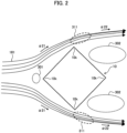
- Fig. 2 illustrates a top view of wind characteristics when the wind 101 flows from an oblique direction into the artificial building 10 having no chamfered shape at the corner portion 10k in the related art, which is similar to Fig. 1 .
- the artificial building 10 acts as an obstacle against the wind 101 flowing in to hit the artificial building 10, thereby generating a force for damming the wind.
- the wind 101 flows to avoid the artificial building 10 (arrow ⁇ 21 in Fig. 2 ). Therefore, in the windward side region of the artificial building 10, the flow wind speed decreases, and thus the wind 101 avoids the artificial building 10, and a speed reduction region 301 is generated.
- the separation phenomenon of the flow occurs at the corner portion 10k of the artificial building 10. Therefore, the wind 101 does not flow along the artificial building 10, but separates from the artificial building 10 based on a wind direction when passing by the corner portion 10k. Therefore, a speed reduction region 302 in which the wind speed decreases due to the influence of the separation phenomenon of the wind 101 from the artificial building 10 is generated.
- the wind 101 separated at the corner portion 10k merges with the surrounding wind 101, so that the kinetic energy (mv 2 /2) of the wind increases, and thus a speed increase region 311 of the high wind speed v is generated outside the corner portion 10k.
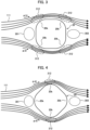
- Fig. 3 illustrates a top view of wind characteristics when wind 111 flows from the front into an artificial building 20 in which a corner portion 20k is made into a chamfered corner round shape in the first embodiment.
- the corner portion 20k is made into a chamfered corner round shape, an arc shape, or a shape having a curvature along which the wind 111 flows, in top view.
- the artificial building 20 acts as an obstacle, thereby generating a force for damming the wind 111. Therefore, the point that the wind flows to avoid the artificial building 20 is similar to the artificial building 10 (see Fig. 1 ) having no chamfered shape. Therefore, in the windward side region of the artificial building 20, the wind speed (arrow ⁇ 31 in Fig. 3 ) decreases so that the wind 111 is separated from the artificial building 20, and the speed reduction region 301 is generated.
- the corner portion 20k is made into a chamfered corner round shape, an arc shape, or a shape having a curvature along which the wind 111 flows.
- the speed reduction region 303 is generated on the leeward side of the artificial building 20, the generation of the speed reduction region 302 (see Figs. 1 and 2 ) due to the separation phenomenon from the artificial building 20 is suppressed.
- the wind 111 that avoids the artificial building 20 merges with the surrounding wind 111, so that the kinetic energy (mv 2 /2) of the wind 111 increases, and the speed increase region 312 in which the wind speed v increases is generated.
- Fig. 4 illustrates a top view of wind characteristics when the wind 111 flows obliquely (toward the corner portion 20k) into the artificial building 20 in which the corner portion 20k is made into a chamfered corner round shape.
- the artificial building 20 acts as an obstacle, thereby generating a force for damming the wind. Therefore, the point that the wind 111 flows to avoid the artificial building 20 is similar to the artificial building 10 having no chamfered shape illustrated in Figs. 1 and 2 .
- the wind speed decreases, and the speed reduction region 301 (see Fig. 4 ) is generated.
- the corner portion 20k is made into a chamfered corner round shape, an arc shape, or a shape having a curvature along which the wind 111 flows, as illustrated in Fig. 4 .
- the speed reduction region 303 is generated on the leeward side of the artificial building 20, the generation of the speed reduction region due to the separation phenomenon from the artificial building 20 is suppressed.
- the wind 111 that avoids the artificial building 20 merges with the surrounding wind 111, so that the kinetic energy (mv 2 /2) of the wind 111 increases, the wind speed v increases, and the speed increase region 312 is generated in the vicinity of the corner portion 20k.
- the corner portion 20k As illustrated in Figs. 3 and 4 , by making the corner portion 20k into a chamfered corner round shape, that is, an arc shape or a shape having a curvature along which the wind 111 flows, the outside of the side wall of the artificial building 20, in particular, the vicinity of the corner portion 20k becomes a speed increase region 312 (see Figs. 3 and 4 ). Therefore, the wind power generation apparatus is disposed outside the vicinity of the corner portion 20k (see Figs. 3 and 4 ). As a result, the wind power generation apparatus can be installed in the speed increase region 312 where large kinetic energy (mv 2 /2) by a high wind speed v is obtained.
- mv 2 /2 large kinetic energy
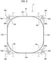
- Fig. 5 illustrates a top view of the artificial building 20 in which a wind power generation apparatus 500 is installed.
- the wind power generation apparatus 500 is installed outside the outer walls of all the four corner portions 20k of the artificial building 20.
- the corner portion 20k is made into a corner round shape which is a chamfered shape, an arc shape, or a shape having a curvature along which the wind 111 flows.
- the artificial building 20 has a chamfered corner portion 20k and two wall surfaces 20m adjacent to the corner portion 20k.
- the wind power generation apparatus 500 includes a blade 500t having a shape that rotates by receiving wind 111, a main shaft 500s that transmits rotational energy of the blade 500t, and a generator (not illustrated) that converts the rotational energy into electricity.
- a wind power generation system S includes the wind power generation apparatus 500 including the blade 500t that rotates by receiving wind 111, the main shaft 500s that transmits rotational energy of the blade 500t, and the generator that converts the rotational energy into electricity, and an artificial building 20 (building) in which the wind power generation apparatus 500 is installed.
- the blade 500t is installed in an installation region r1 including the corner portion 20k of the artificial building 20 and a surface having each of two wall surfaces 20m adjacent to the corner portion 20k.
- kinetic energy of the wind 111 is converted into rotational energy for rotating the blade 500t, by using the blade 500t.
- the rotational energy of the blade 500t is converted into electric energy by the generator.
- the kinetic energy (mv 2 /2) of the wind 111 changes depending on the wind speed v. That is, as the wind speed v increases, the kinetic energy of the wind 111 increases. Therefore, the electricity obtained from the wind power generation apparatus 500 also depends on the wind speed v. Therefore, in order to realize a larger amount of power generation, it is necessary to install the wind power generation apparatus 500 in a region where the wind speed v is high (a region where the kinetic energy of the wind 111 is high).
- the wind power generation apparatus 500 can be installed in the speed increase region 312 by utilizing the corner portion 20k of the artificial building 20.
- the wind power generation apparatus 500 is installed in the vicinity of all the four corner portions 20k. As a result, any wind power generation apparatus 500 is normally located in the speed increase region 312 regardless of the wind direction from which the wind is blown (see Figs. 3 and 4 ). Therefore, under any wind direction condition, the wind power generation apparatus 500 can continue a power generation operation in which the amount of power generation increases in the speed increase region 312 (see Figs. 3 and 4 ).
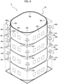
- Fig. 6 illustrates a three-dimensional view of the artificial building 20 in which the wind power generation apparatus 500 is installed.
- a plurality of wind power generation apparatuses 500 can be installed in the vertical direction in the artificial building 20. Therefore, in the artificial building 20 which is a high-rise building, it is possible to install a large number of wind power generation apparatuses 500 even in the altitude direction.
- the wind power generation apparatus 500 is installed in accordance with the height of a structural support member 510 that supports each floor 20f in the artificial building 20. Since the wind power generation apparatus 500 is supported by the structural support member 510, the wind power generation apparatus 500, which is a heavy object, can be safely held on each floor 20f of the artificial building 20.
- the artificial building 20 being the building includes the structural support member (protrusion) 510 in the installation region r1.
- the blade 500t is installed at the structural support member (protrusion) 510.
- the wind power generation apparatus 500 can be installed in the speed increase region 312 (see Figs. 3 and 4 ), and a large number of wind power generation apparatuses 500 can be installed in the altitude direction (see Fig. 6 ). As a result, it is possible to realize a large amount of power generation from the artificial building 20.
- the shape of the corner portion 20k of the artificial building 20 is changed to a corner round shape, an arc shape, or a shape having a curvature along which the wind 111 flows, thereby suppressing the separation phenomenon of the flow.
- the wind power generation apparatus 500 expected to generate a high amount of power in various wind directions illustrated in Figs. 3 and 4 can be installed.
- the occurrence of the separation phenomenon at the corner portion 20k in the artificial building 20 is suppressed by utilizing the speed increase region 312 around the artificial building 20, and the speed reduction regions 301 and 303 around the artificial building 20 are reduced. Therefore, the wind power generation apparatus 500 can be more easily installed in the speed increase region 312.
- the second embodiment is different from the first embodiment in that, in the wind power generation apparatus 500 in the second embodiment, the notch shape of the corner portion 20k in the first embodiment illustrated in Figs. 3 and 4 is made into a corner cut shape.
- the artificial building 30 acts as an obstacle, thereby generating a force for damming the wind. Therefore, the point that the wind 112 flows to avoid the artificial building 30 is similar to the artificial building 10 (see Figs. 1 and 2 ) having no chamfered shape and the artificial building 20 in which the corner portion 20k (see Figs. 3 and 4 ) is made into a chamfered corner round shape. Therefore, in the windward side region of the artificial building 30, the wind 112 escapes from the artificial building 30, thereby decreasing the wind speed and generating the speed reduction region 301.
- the corner portion 30k is made into a chamfered corner cut shape or a shape obtained by cutting the corner portion 30k in a plane.
- the wind 112 (arrow ⁇ 51 in Fig. 7 ) that avoids the artificial building 30 merges with the surrounding wind 112, so that the kinetic energy (mv 2 /2) of the wind 112 increases, and the speed increase region 312 in which the wind speed v increases is generated.
- Fig. 8 illustrates a top view of wind characteristics when the wind 112 flows obliquely into the artificial building 30 in which the corner portion 30k is made into a chamfered corner cut shape in the second embodiment.
- the wind 112 that obliquely hits the artificial building 30 (to the corner portion 30k of the artificial building 30) and flows into the artificial building 30 acts as an obstacle to generate a force for damming the wind 112. Therefore, the point that the wind flows to avoid the artificial building 30 is similar to the artificial building 10 having no chamfered shape illustrated in Figs. 1 and 2 .
- the corner portion 30k is made into a chamfered corner cut shape or a shape obtained by cutting the corner portion 30k in a plane, whereby the occurrence of the separation phenomenon of the flow from the artificial building 30 is suppressed, and the wind 112 flows along the artificial building 30.
- the wind 112 that avoids the artificial building 30 merges with the surrounding wind 112, so that the kinetic energy of the wind 112 increases, and the speed increase region 312 of the wind 112 is generated in the vicinity of the corner portion 30k.
- the speed increase region 312 is smaller than the corner portion 20k of the corner round shape illustrated in Figs. 3 and 4 .
- the occurrence of the separation phenomenon from the artificial building 30 is very suppressed.
- the outside of the side wall of the artificial building 30, particularly, the vicinity of the corner portion 30k becomes the speed increase region 312 (see Figs. 7 and 8 ).
- the wind power generation apparatus 500 is disposed in the vicinity of the corner portion 30k, so that the wind power generation apparatus 500 can be installed in the speed increase region 312 (see Figs. 7 and 8 ) where the high wind speed v is expected.
- Fig. 9 illustrates a top view of the artificial building 30 in which the wind power generation apparatus 500 in the second embodiment is installed.
- the wind power generation apparatus 500 in the second embodiment is installed outside the outer wall of the corner portion 30k of the artificial building 30 and on all four sides.
- the corner portion 30k is made into a corner cut shape or a chamfered shape obtained by cutting a sharp corner in a plane.
- the artificial building 30 has a chamfered corner portion 30k and two wall surfaces 30m adjacent to the corner portion 30k.
- a wind power generation system S1 includes the wind power generation apparatus 500 including the blade 500t that rotates by receiving wind 112, the main shaft 500s that transmits rotational energy of the blade 500t, and the generator that converts the rotational energy into electricity, and the artificial building 30 (building) in which the wind power generation apparatus 500 is installed.
- the wind power generation apparatus 500 is installed near the corner portion 30k of the artificial building 30, so that the wind power generation apparatus 500 can be installed in the speed increase region 312 (see Figs. 7 and 8 ).
- the blade 500t is installed in an installation region r2 including the corner portion 30k of the artificial building 30 and a surface having each of two wall surfaces 30m adjacent to the corner portion 30k.
- any wind power generation apparatus 500 is normally located in the speed increase region 312 regardless of the wind direction from which the wind 112 is blown. As a result, the wind power generation apparatus 500 can continue the power generation operation with high power generation efficiency under any wind direction condition.
- a plurality of wind power generation apparatuses 500 can be installed in the vertical direction. Therefore, it is possible to install a large number of wind power generation apparatuses 500 in a high-rise building.
- the wind power generation apparatus 500 is installed in accordance with the height of the structural support member 510 of each floor in the artificial building 30, and the wind power generation apparatus 500, which is a heavy object, can be supported by the structural support member 510 and safely held in the artificial building 30.
- the wind power generation apparatus 500 can be installed in the speed increase region 312 (see Figs. 7 and 8 ), and a large number of wind power generation apparatuses 500 can be installed in the altitude direction. Therefore, it is possible to realize a large amount of power generation from the artificial building 30.
- the wind power generation apparatus 500 can be more easily applied to the artificial building 30.
- Fig. 10 illustrates a top view of a method of installing a wind power generation apparatus according to a third embodiment.
- the wind power generation apparatus 500 is installed so as to have a changeable position (arrows ⁇ 11 and ⁇ 12 in Fig. 10 ) in a region 20r (shaded portion in Fig. 10 ) inside the chamfered shape of the corner portion 20k of the artificial building 20 (region 30r (see Fig. 9 ) inside the chamfered shape of the corner portion 30k).
- the speed increase region 312 has a characteristic that changes in accordance with the wind status flowing into the artificial buildings 20 and 30.
- the place most suitable for installation of the wind power generation apparatus 500 also changes in accordance with the wind 111 and the wind 112 flowing into the artificial buildings 20 and 30.
- One of factors that change the characteristics of the wind 111 and the wind 112 flowing into the artificial buildings 20 and 30 is a change in the surrounding environment of the artificial buildings 20 and 30.
- the wind power generation apparatus 500 is installed with a position changing unit 500i (see Fig. 10 ) such that the position is changeable on the structural support member 510 in the region 20r (shaded portion in Fig. 10 ) at a corner round chamfered shape portion in the artificial building 20 (region 30r (see Fig. 9 ) inside the corner round chamfered shape of the corner portion 30k in the artificial building 30).
- the position changing unit 500i that installs the wind power generation apparatus 500 to have a changeable position, lays a rail (not illustrated) on which the wind power generation apparatus 500 moves is laid on the structural support member 510, and the wind power generation apparatus 500 is fixed on the rail of the position changing unit 500i.
- the wind power generation apparatus 500 is provided with the position changing unit 500i having legs, and the legs of the position changing unit 500i are portable instead of the rail structure.
- Other configurations may be adopted as long as the position of the wind power generation apparatus 500 can be changed.
- the position changing unit 500i changes the installation position of the wind power generation apparatus 500 in accordance with the surrounding environment such as the situation of the surrounding building.
- the wind power generation apparatus 500 With a configuration in which the wind power generation apparatus 500 is made movable and can change the position, it is possible to move and install the wind power generation apparatus 500 to a position where a higher amount of power generation is expected.
- Fig. 11 is a block diagram for determining the installation position of a control unit 600c of a wind power generation apparatus 500 according to a fourth embodiment.
- the wind power generation apparatus 500 in the fourth embodiment is an example of a control method of determining the installation position in accordance with the surrounding environment.
- the speed increase region 312 around the artificial buildings 10 and 20 suitable for installation of the wind power generation apparatus 500 changes in accordance with the surrounding environment of the building and the wind directions of the winds 111 and the wind 112.
- the installation position of the wind power generation apparatus 500 is determined by using the control unit 600c in accordance with the surrounding environment and the wind direction.
- the control unit 600c that controls the position of the wind power generation apparatus 500 includes a wind direction reading unit 600, a wind status evaluation unit 601, a position calculation unit 602, a position output unit 603, and a wind status recording unit 610.
- the control unit 600c is realized by software stored in a computer such as a personal computer.
- the control unit 600c may be partially configured by hardware.
- the wind direction reading unit 600 is an input unit that reads data of the wind direction provided by the Meteorological Agency, data of a wind vane installed on the roof, data of the wind direction distributed to the private sector, and the like.
- wind status data of the speed increase region 312, the speed reduction regions 301, 302, and 303, and the like is recorded by analysis in advance.
- the wind status data recorded in the wind status recording unit 610 may be data measured on site, data reproduced by a reduced model such as a wind tunnel experiment prepared in advance, or a wind status simulation result based on numerical fluid dynamics.
- the control unit 600c which is a position control device, first takes in an inflow wind direction into the artificial buildings 20 and 30 in which the wind power generation apparatus 500 is installed in the wind direction reading unit 600.
- examples of wind direction data taken into the wind direction reading unit 600 include weather data and weather forecast data disclosed by the Meteorological Agency, wind direction data measured around the artificial buildings 20 and 30, and the like.
- a known representative wind direction of a region where the artificial buildings 20 and 30 are constructed or a target season may be used.
- the wind direction data taken by the wind direction reading unit 600 is transmitted to the wind status evaluation unit 601 and used to evaluate the wind status around the artificial buildings 20 and 30.
- the wind status evaluation unit 601 reads wind status data around the artificial buildings 20 and 30 from the wind status recording unit 610 in addition to the wind direction data.
- the wind status evaluation unit 601 reproduces the wind status ( Figs. 3 , 7 , and the like) around the artificial buildings 20 and 30 from the wind direction data and the wind status data evaluated in advance.
- the position calculation unit 602 extracts the speed increase region 312 from the wind status data obtained by the wind status evaluation unit 601, and determines the installation position suitable for the wind power generation apparatus 500 in the speed increase region 312 ( Figs. 3, 4 , 7, and 8 ).
- a command value of the installation position most suitable for installation of the wind power generation apparatus 500 in the chamfered shape (see Figs. 5 and 9 ) of the corner portions 20k and 30k of the artificial buildings 20 and 30 is output from the position output unit 603.
- the position changing unit 500i (see Fig. 10 ) changes the position of the wind power generation apparatus 500 in accordance with the command value from the control unit 600c.
- the fourth embodiment it is possible to normally evaluate the speed increase region 312 suitable for installation of the wind power generation apparatus 500 in consideration of the influence of the change in wind status around the artificial buildings 20 and 30 caused in accordance with the surrounding environment and the change in the wind direction.
- the wind power generation apparatus 500 can be installed in the speed increase region 312 ( Figs. 3, 4 , 7, and 8 ) where a higher amount of power generation is expected.
Landscapes
- Engineering & Computer Science (AREA)
- Life Sciences & Earth Sciences (AREA)
- Sustainable Development (AREA)
- Sustainable Energy (AREA)
- Chemical & Material Sciences (AREA)
- Combustion & Propulsion (AREA)
- Mechanical Engineering (AREA)
- General Engineering & Computer Science (AREA)
- Power Engineering (AREA)
- Wind Motors (AREA)
Abstract
According to the present invention, a wind power generation system includes: a wind power generation apparatus including a blade that rotates by receiving wind, a main shaft that transmits rotational energy of the blade, and a generator that converts the rotational energy into electricity; and a building in which the wind power generation apparatus is installed, in which the building includes a corner portion having a chamfered shape and two wall surfaces adjacent to the corner portion, and the blade is installed in an installation region including the corner portion and a surface having each of the two wall surfaces adjacent to the corner portion.
Description
- The present invention relates to a wind power generation system, a method of using a wind power generation apparatus, and a building in which the wind power generation apparatus is installed.
- One of efforts for global warming countermeasures is the use of renewable energy.
- Therefore, local production and local consumption of electric power for securing renewable energy without passing through an electric power system has attracted attention.
- As an approach to local production and local consumption, a wind power generation apparatus is being installed near a building.
- In the vicinity of an artificial building represented by a building, wind collides with the artificial building to change characteristics of a wind flow. In particular, it is known that a separation phenomenon called separation of a wind flow occurs at a corner portion of an artificial building because the shape of the corner portion changes rapidly into a concave shape. Due to the change in characteristics of wind such as a separation phenomenon, a speed increase region where the wind speed increases and a speed reduction region where the wind speed decreases are generated around the artificial building.
- On the other hand, the amount of power generation in the wind power generation apparatus depends on the wind speed. Therefore, in order to secure the amount of power generation, it is desirable to install a wind power generation apparatus at a place where the wind speed is high.
- As a method of installing a wind power generation apparatus in an artificial building, for example, techniques disclosed in
JP 2002-98037 A Figs. 1 to 3 , the paragraphs [0013] to [0015], and the like) andJP 2011-174448 A Figs. 1 and2 , the paragraphs [0027] and [0028], and the like) are known. - As described above, the separation phenomenon of the flow is a phenomenon in which wind flowing along an artificial building flows to be separated from a wall surface of the artificial building around a corner portion of the artificial building. Due to this phenomenon, both a region where the wind speed increases (speed increase region) and a region where the wind speed decreases (speed reduction region) are generated around the artificial building, and these regions are mixed.
- Therefore, the wind power generation apparatus is desirably installed at a position of a high wind speed because the amount of power generation depends on the level of the wind speed.
- Thus, around the artificial building, it is possible to expect a larger amount of power generation by installing the wind power generation apparatus in the speed increase region where the wind speed is high.
- Therefore, in
JP 2002-98037 A JP 2011-174448 A -
JP 2002-98037 A JP 2002-98037 A JP 2002-98037 A - In
JP 2011-174448 A JP 2011-174448 A - However, in the case of the wind power generation methods disclosed in
JP 2002-98037 A JP 2011-174448 A - The present invention has been made in view of the above circumstances, and an object of the present invention is to provide a wind power generation system that is expected to generate a high amount of power even in various wind directions, a method of using a wind power generation apparatus, and a building in which the wind power generation apparatus is installed.
- In order to achieve the above object, according to the present invention, a wind power generation system includes: a wind power generation apparatus including a blade that rotates by receiving wind, a main shaft that transmits rotational energy of the blade, and a generator that converts the rotational energy into electricity; and a building in which the wind power generation apparatus is installed, in which the building includes a corner portion having a chamfered shape and two wall surfaces adjacent to the corner portion, and the blade is installed in an installation region including the corner portion and a surface having each of the two wall surfaces adjacent to the corner portion.
- According to the present invention, it is possible to provide a wind power generation system that is expected to generate a high amount of power even in various wind directions, a method of using a wind power generation apparatus, and a building in which the wind power generation apparatus is installed.
-
-
Fig. 1 is a top view of wind characteristics when wind flows from the front into an artificial building having no chamfered shape in the related art; -
Fig. 2 is a top view of wind characteristics when the wind obliquely flows into the artificial building having no chamfered shape in the related art; -
Fig. 3 is a top view of wind characteristics when the wind flows from the front into an artificial building in which a corner portion has a chamfered shape, and a chamfered portion is made into a corner round shape; -
Fig. 4 is a top view of wind characteristics when the wind obliquely flows into the artificial building in which the corner portion has the chamfered shape, and the chamfered portion is made into the corner round shape; -
Fig. 5 is a top view of a method of installing a wind power generation apparatus according to a first embodiment; -
Fig. 6 is a three-dimensional view of the method of installing the wind power generation apparatus according to the first embodiment; -
Fig. 7 is a top view of wind characteristics when the wind flows from the front into an artificial building in which the corner portion has the chamfered shape, and the chamfered portion is made into a corner cut shape; -
Fig. 8 is a top view of wind characteristics when the wind obliquely flows into the artificial building in which the corner portion has the chamfered shape, and the chamfered portion is made into the corner cut shape; -
Fig. 9 is a top view of a method of installing a wind power generation apparatus according to a second embodiment; -
Fig. 10 is a top view of a method of installing a wind power generation apparatus according to a third embodiment; and -
Fig. 11 illustrates a method of determining an installation position of a wind power generation apparatus according to a fourth embodiment. - The present invention relates to a wind power generation apparatus installed in an artificial building. In particular, as a method of installing a wind power generation apparatus in an urban area, it is possible to achieve high power generation by effectively utilizing a change in wind, which is caused by the shape of an artificial building.
- Embodiments of the present invention will be appropriately described below in detail with reference to the drawings.
- In the description in this specification, a vertical-axis wind power generation apparatus will be described as the wind power generation apparatus according to the embodiments of the present invention. However, the present invention can be similarly applied to another type of vertical-axis wind power generation apparatus or a horizontal-axis wind power generation apparatus.
- In addition, a rectangular parallelepiped shape will be described as an artificial building. However, as long as the shape has a corner portion, the cross-sectional shape of the artificial building in the present invention is not limited to a quadrangle, and may be a triangle, a pentagon, or a polygon in a top view. The height of the artificial building can be applied to both the lower layer and the higher layer.
- The embodiments described below do not limit the inventions according to the claims, and all the elements and combinations described in the embodiments are not necessarily essential for the solution of the invention.
- In the drawings, the same components are denoted by the same reference signs, and the detailed description of the repetitive parts will be omitted.
-
Fig. 1 illustrates a top view of wind characteristics whenwind 101 flows into anartificial building 10 having no chamfered shape at acorner portion 10k from the front in the related art. - When the
wind 101 flows into theartificial building 10 to hit theartificial building 10, theartificial building 10 acts as an obstacle, thereby generating a force for damming thewind 101. Therefore, thewind 101 flows to avoid the artificial building 10 (arrow α11 inFig. 1 ). - Thus, in a windward side region of the
artificial building 10, the flow wind speed decreases so that thewind 101 avoids theartificial building 10, and thus aspeed reduction region 301 is generated. - Further, a separation phenomenon (arrow α12 in
Fig. 1 ) of a flow in which thewind 101 separates from theartificial building 10 occurs near thecorner portion 10k of theartificial building 10. That is, thewind 101 does not flow along theartificial building 10, but separates from theartificial building 10 based on a wind direction when passing by thecorner portion 10k (arrow α12 inFig. 1 ). - Therefore, a
speed reduction region 302 in which the wind speed decreases due to the influence of the separation phenomenon of thewind 101 from theartificial building 10 is generated. - A
speed reduction region 303 is generated on a leeward side of theartificial building 10, because thewind 101 is blocked by theartificial building 10, and thus does not flows into theartificial building 10. - On the other hand, as indicated by an arrow α12 in
Fig. 1 , theseparated wind 101 merges with the surroundingwind 101 in the vicinity of thecorner portion 10k of theartificial building 10, so that the kinetic energy (mv2/2) of thewind 101 increases. As a result, a speed increaseregion 311 in which the wind speed v of thewind 101 is high is generated outside thecorner portion 10k. -
Fig. 2 illustrates a top view of wind characteristics when thewind 101 flows from an oblique direction into theartificial building 10 having no chamfered shape at thecorner portion 10k in the related art, which is similar toFig. 1 . - Even when the
wind 101 is blown from the oblique direction of the artificial building 10 (toward thecorner portion 10k of the artificial building 10), theartificial building 10 acts as an obstacle against thewind 101 flowing in to hit theartificial building 10, thereby generating a force for damming the wind. - Therefore, the
wind 101 flows to avoid the artificial building 10 (arrow α21 inFig. 2 ). Therefore, in the windward side region of theartificial building 10, the flow wind speed decreases, and thus thewind 101 avoids theartificial building 10, and aspeed reduction region 301 is generated. - Further, as indicated by an arrow α22 in
Fig. 2 , the separation phenomenon of the flow occurs at thecorner portion 10k of theartificial building 10. Therefore, thewind 101 does not flow along theartificial building 10, but separates from theartificial building 10 based on a wind direction when passing by thecorner portion 10k. Therefore, aspeed reduction region 302 in which the wind speed decreases due to the influence of the separation phenomenon of thewind 101 from theartificial building 10 is generated. - On the other hand, the
wind 101 separated at thecorner portion 10k merges with the surroundingwind 101, so that the kinetic energy (mv2/2) of the wind increases, and thus aspeed increase region 311 of the high wind speed v is generated outside thecorner portion 10k. - As illustrated in
Figs. 1 and2 , in theartificial building 10 having thecorner portion 10k (seeFigs. 1 and2 ), most of the periphery of theartificial building 10 is thespeed reduction regions wind 101 from theartificial building 10, and thus, there are many regions where the wind speed v is low. Therefore, it has become clear that the vicinity of thecorner portion 10k of theartificial building 10 is not suitable for installation of the wind power generation apparatus because the wind speed v is low and the kinetic energy is small. - A method of installing the wind power generation apparatus according to the first embodiment will be described with reference to
Figs. 3 to 6 . -
Fig. 3 illustrates a top view of wind characteristics whenwind 111 flows from the front into anartificial building 20 in which acorner portion 20k is made into a chamfered corner round shape in the first embodiment. - As illustrated in
Fig. 3 , in theartificial building 20 of the first embodiment, thecorner portion 20k is made into a chamfered corner round shape, an arc shape, or a shape having a curvature along which thewind 111 flows, in top view. - As illustrated in
Fig. 3 , when thewind 111 flows into theartificial building 20 to hit theartificial building 20, theartificial building 20 acts as an obstacle, thereby generating a force for damming thewind 111. Therefore, the point that the wind flows to avoid theartificial building 20 is similar to the artificial building 10 (seeFig. 1 ) having no chamfered shape. Therefore, in the windward side region of theartificial building 20, the wind speed (arrow α31 inFig. 3 ) decreases so that thewind 111 is separated from theartificial building 20, and thespeed reduction region 301 is generated. - On the other hand, in the
artificial building 20, thecorner portion 20k is made into a chamfered corner round shape, an arc shape, or a shape having a curvature along which thewind 111 flows. - As a result, an occurrence of the separation phenomenon of the flow of
wind 111 from theartificial building 20 is suppressed, and thewind 111 flows along the artificial building 20 (near the artificial building 20). - Therefore, although the
speed reduction region 303 is generated on the leeward side of theartificial building 20, the generation of the speed reduction region 302 (seeFigs. 1 and2 ) due to the separation phenomenon from theartificial building 20 is suppressed. On the other hand, at thecorner portion 20k, thewind 111 that avoids theartificial building 20 merges with the surroundingwind 111, so that the kinetic energy (mv2/2) of thewind 111 increases, and thespeed increase region 312 in which the wind speed v increases is generated. -
Fig. 4 illustrates a top view of wind characteristics when thewind 111 flows obliquely (toward thecorner portion 20k) into theartificial building 20 in which thecorner portion 20k is made into a chamfered corner round shape. - When the
wind 111 flows into the artificial building 20 (toward thecorner portion 20k), theartificial building 20 acts as an obstacle, thereby generating a force for damming the wind. Therefore, the point that thewind 111 flows to avoid theartificial building 20 is similar to theartificial building 10 having no chamfered shape illustrated inFigs. 1 and2 . - Therefore, in the windward side region of the
artificial building 20, the wind speed decreases, and the speed reduction region 301 (seeFig. 4 ) is generated. - On the other hand, in the
artificial building 20, thecorner portion 20k is made into a chamfered corner round shape, an arc shape, or a shape having a curvature along which thewind 111 flows, as illustrated inFig. 4 . - Due to the shape of the
corner portion 20k, the occurrence of the separation phenomenon of the flow from theartificial building 20 is suppressed, and thewind 111 flows along theartificial building 20. - Therefore, although the
speed reduction region 303 is generated on the leeward side of theartificial building 20, the generation of the speed reduction region due to the separation phenomenon from theartificial building 20 is suppressed. In addition, thewind 111 that avoids theartificial building 20 merges with the surroundingwind 111, so that the kinetic energy (mv2/2) of thewind 111 increases, the wind speed v increases, and thespeed increase region 312 is generated in the vicinity of thecorner portion 20k. - As illustrated in
Figs. 3 and 4 , by making thecorner portion 20k into a chamfered corner round shape, that is, an arc shape or a shape having a curvature along which thewind 111 flows, the outside of the side wall of theartificial building 20, in particular, the vicinity of thecorner portion 20k becomes a speed increase region 312 (seeFigs. 3 and 4 ). Therefore, the wind power generation apparatus is disposed outside the vicinity of thecorner portion 20k (seeFigs. 3 and 4 ). As a result, the wind power generation apparatus can be installed in thespeed increase region 312 where large kinetic energy (mv2/2) by a high wind speed v is obtained. -
Fig. 5 illustrates a top view of theartificial building 20 in which a windpower generation apparatus 500 is installed. - The wind
power generation apparatus 500 is installed outside the outer walls of all the fourcorner portions 20k of theartificial building 20. Thecorner portion 20k is made into a corner round shape which is a chamfered shape, an arc shape, or a shape having a curvature along which thewind 111 flows. - The
artificial building 20 has a chamferedcorner portion 20k and twowall surfaces 20m adjacent to thecorner portion 20k. - The wind
power generation apparatus 500 includes ablade 500t having a shape that rotates by receivingwind 111, amain shaft 500s that transmits rotational energy of theblade 500t, and a generator (not illustrated) that converts the rotational energy into electricity. - A wind power generation system S according to the first embodiment includes the wind
power generation apparatus 500 including theblade 500t that rotates by receivingwind 111, themain shaft 500s that transmits rotational energy of theblade 500t, and the generator that converts the rotational energy into electricity, and an artificial building 20 (building) in which the windpower generation apparatus 500 is installed. - The
blade 500t is installed in an installation region r1 including thecorner portion 20k of theartificial building 20 and a surface having each of twowall surfaces 20m adjacent to thecorner portion 20k. - In the wind
power generation apparatus 500, kinetic energy of thewind 111 is converted into rotational energy for rotating theblade 500t, by using theblade 500t. The rotational energy of theblade 500t is converted into electric energy by the generator. - The kinetic energy (mv2/2) of the
wind 111 changes depending on the wind speed v. That is, as the wind speed v increases, the kinetic energy of thewind 111 increases. Therefore, the electricity obtained from the windpower generation apparatus 500 also depends on the wind speed v. Therefore, in order to realize a larger amount of power generation, it is necessary to install the windpower generation apparatus 500 in a region where the wind speed v is high (a region where the kinetic energy of thewind 111 is high). - In the first embodiment, as illustrated in
Figs. 3 and 4 , the windpower generation apparatus 500 can be installed in thespeed increase region 312 by utilizing thecorner portion 20k of theartificial building 20. - As illustrated in
Fig. 5 , the windpower generation apparatus 500 is installed in the vicinity of all the fourcorner portions 20k. As a result, any windpower generation apparatus 500 is normally located in thespeed increase region 312 regardless of the wind direction from which the wind is blown (seeFigs. 3 and 4 ). Therefore, under any wind direction condition, the windpower generation apparatus 500 can continue a power generation operation in which the amount of power generation increases in the speed increase region 312 (seeFigs. 3 and 4 ). -
Fig. 6 illustrates a three-dimensional view of theartificial building 20 in which the windpower generation apparatus 500 is installed. - A plurality of wind
power generation apparatuses 500 can be installed in the vertical direction in theartificial building 20. Therefore, in theartificial building 20 which is a high-rise building, it is possible to install a large number of windpower generation apparatuses 500 even in the altitude direction. - In addition, the wind
power generation apparatus 500 is installed in accordance with the height of astructural support member 510 that supports eachfloor 20f in theartificial building 20. Since the windpower generation apparatus 500 is supported by thestructural support member 510, the windpower generation apparatus 500, which is a heavy object, can be safely held on eachfloor 20f of theartificial building 20. - In other words, the
artificial building 20 being the building includes the structural support member (protrusion) 510 in the installation region r1. Theblade 500t is installed at the structural support member (protrusion) 510. - From the above description, according to the first embodiment, the wind
power generation apparatus 500 can be installed in the speed increase region 312 (seeFigs. 3 and 4 ), and a large number of windpower generation apparatuses 500 can be installed in the altitude direction (seeFig. 6 ). As a result, it is possible to realize a large amount of power generation from theartificial building 20. - Therefore, in the first embodiment, the shape of the
corner portion 20k of theartificial building 20 is changed to a corner round shape, an arc shape, or a shape having a curvature along which thewind 111 flows, thereby suppressing the separation phenomenon of the flow. As a result, the windpower generation apparatus 500 expected to generate a high amount of power in various wind directions illustrated inFigs. 3 and 4 can be installed. - According to the first embodiment, the occurrence of the separation phenomenon at the
corner portion 20k in theartificial building 20 is suppressed by utilizing thespeed increase region 312 around theartificial building 20, and thespeed reduction regions artificial building 20 are reduced. Therefore, the windpower generation apparatus 500 can be more easily installed in thespeed increase region 312. - Therefore, it is possible to provide the method of installing the wind
power generation apparatus 500 expected to generate a higher amount of power. - Next, a method of installing a wind
power generation apparatus 500 according to a second embodiment will be described with reference toFigs. 7 to 9 . -
Fig. 7 illustrates a top view of wind characteristics whenwind 112 flows from the front into anartificial building 30 in which acorner portion 30k is made into a chamfered corner cut shape in the second embodiment. - The second embodiment is different from the first embodiment in that, in the wind
power generation apparatus 500 in the second embodiment, the notch shape of thecorner portion 20k in the first embodiment illustrated inFigs. 3 and 4 is made into a corner cut shape. - As illustrated in
Fig. 7 , when thewind 112 flows into theartificial building 30 to hit theartificial building 30, theartificial building 30 acts as an obstacle, thereby generating a force for damming the wind. Therefore, the point that thewind 112 flows to avoid theartificial building 30 is similar to the artificial building 10 (seeFigs. 1 and2 ) having no chamfered shape and theartificial building 20 in which thecorner portion 20k (seeFigs. 3 and 4 ) is made into a chamfered corner round shape. Therefore, in the windward side region of theartificial building 30, thewind 112 escapes from theartificial building 30, thereby decreasing the wind speed and generating thespeed reduction region 301. - In the
artificial building 30 in the second embodiment, thecorner portion 30k is made into a chamfered corner cut shape or a shape obtained by cutting thecorner portion 30k in a plane. As a result, similarly to theartificial building 20 illustrated inFigs. 3 and 4 , the occurrence of the separation phenomenon of the flow ofwind 112 from theartificial building 30 is suppressed, and thewind 112 flows along theartificial building 30. - Therefore, as illustrated in
Fig. 7 , although thespeed reduction region 303 is generated on the leeward side of theartificial building 30, the generation of the speed reduction region 302 (seeFig. 1 ) due to the separation phenomenon is suppressed. - On the other hand, at the
corner portion 30k, the wind 112 (arrow α51 inFig. 7 ) that avoids theartificial building 30 merges with the surroundingwind 112, so that the kinetic energy (mv2/2) of thewind 112 increases, and thespeed increase region 312 in which the wind speed v increases is generated. -
Fig. 8 illustrates a top view of wind characteristics when thewind 112 flows obliquely into theartificial building 30 in which thecorner portion 30k is made into a chamfered corner cut shape in the second embodiment. - The
wind 112 that obliquely hits the artificial building 30 (to thecorner portion 30k of the artificial building 30) and flows into theartificial building 30 acts as an obstacle to generate a force for damming thewind 112. Therefore, the point that the wind flows to avoid theartificial building 30 is similar to theartificial building 10 having no chamfered shape illustrated inFigs. 1 and2 . - Therefore, as illustrated in
Fig. 8 , in the windward side region of theartificial building 30, thewind 112 escapes, thereby decreasing the wind speed and generating thespeed reduction region 301. - On the other hand, in the
artificial building 30, thecorner portion 30k is made into a chamfered corner cut shape or a shape obtained by cutting thecorner portion 30k in a plane, whereby the occurrence of the separation phenomenon of the flow from theartificial building 30 is suppressed, and thewind 112 flows along theartificial building 30. - Therefore, although the speed reduction region 303 (see
Fig. 8 ) is generated on the leeward side of theartificial building 30, the generation of the speed reduction region 302 (seeFig. 1 ) due to the separation phenomenon from theartificial building 30 is suppressed. - On the other hand, the
wind 112 that avoids theartificial building 30 merges with the surroundingwind 112, so that the kinetic energy of thewind 112 increases, and thespeed increase region 312 of thewind 112 is generated in the vicinity of thecorner portion 30k. - As illustrated in
Figs. 7 and 8 , when thecorner portion 30k is made into a chamfered corner cut shape or a shape obtained by cutting thecorner portion 30k in a plane, thespeed increase region 312 is smaller than thecorner portion 20k of the corner round shape illustrated inFigs. 3 and 4 . However, compared with theartificial building 10 having a sharpangular corner portion 10k illustrated inFigs. 1 and2 , the occurrence of the separation phenomenon from theartificial building 30 is very suppressed. - Therefore, the outside of the side wall of the
artificial building 30, particularly, the vicinity of thecorner portion 30k becomes the speed increase region 312 (seeFigs. 7 and 8 ). - Thus, even when the chamfered shape of the
corner portion 30k illustrated inFigs. 7 and 8 is made into a corner cut shape or a shape obtained by cutting the corner portion in a plane, the windpower generation apparatus 500 is disposed in the vicinity of thecorner portion 30k, so that the windpower generation apparatus 500 can be installed in the speed increase region 312 (seeFigs. 7 and 8 ) where the high wind speed v is expected. -
Fig. 9 illustrates a top view of theartificial building 30 in which the windpower generation apparatus 500 in the second embodiment is installed. - The wind
power generation apparatus 500 in the second embodiment is installed outside the outer wall of thecorner portion 30k of theartificial building 30 and on all four sides. Thecorner portion 30k is made into a corner cut shape or a chamfered shape obtained by cutting a sharp corner in a plane. - The
artificial building 30 has a chamferedcorner portion 30k and twowall surfaces 30m adjacent to thecorner portion 30k. - A wind power generation system S1 according to the second embodiment includes the wind
power generation apparatus 500 including theblade 500t that rotates by receivingwind 112, themain shaft 500s that transmits rotational energy of theblade 500t, and the generator that converts the rotational energy into electricity, and the artificial building 30 (building) in which the windpower generation apparatus 500 is installed. - In the second embodiment, as illustrated in
Figs. 7 and 8 , the windpower generation apparatus 500 is installed near thecorner portion 30k of theartificial building 30, so that the windpower generation apparatus 500 can be installed in the speed increase region 312 (seeFigs. 7 and 8 ). - The
blade 500t is installed in an installation region r2 including thecorner portion 30k of theartificial building 30 and a surface having each of twowall surfaces 30m adjacent to thecorner portion 30k. - In addition, as illustrated in
Fig. 9 , by installing the windpower generation apparatuses 500 at all the fourcorner portions 30k, as illustrated inFigs. 7 and 8 , any windpower generation apparatus 500 is normally located in thespeed increase region 312 regardless of the wind direction from which thewind 112 is blown. As a result, the windpower generation apparatus 500 can continue the power generation operation with high power generation efficiency under any wind direction condition. - Also in the second embodiment, similarly to the first embodiment in
Fig. 6 , a plurality of windpower generation apparatuses 500 can be installed in the vertical direction. Therefore, it is possible to install a large number of windpower generation apparatuses 500 in a high-rise building. - Similarly to
Fig. 6 , the windpower generation apparatus 500 is installed in accordance with the height of thestructural support member 510 of each floor in theartificial building 30, and the windpower generation apparatus 500, which is a heavy object, can be supported by thestructural support member 510 and safely held in theartificial building 30. - As described above, according to the second embodiment, the wind
power generation apparatus 500 can be installed in the speed increase region 312 (seeFigs. 7 and 8 ), and a large number of windpower generation apparatuses 500 can be installed in the altitude direction. Therefore, it is possible to realize a large amount of power generation from theartificial building 30. - In addition, by making the
corner portion 30k into a corner cut shape or a shape obtained by cutting the sharp corner portion in a plane, it is possible to construct the building in a linear structure. Thus, the windpower generation apparatus 500 can be more easily applied to theartificial building 30. -
Fig. 10 illustrates a top view of a method of installing a wind power generation apparatus according to a third embodiment. - Next, a method of installing a wind
power generation apparatus 500 according to a third embodiment will be described with reference toFig. 10 . - In the third embodiment, the wind
power generation apparatus 500 is installed so as to have a changeable position (arrows α11 and α12 inFig. 10 ) in aregion 20r (shaded portion inFig. 10 ) inside the chamfered shape of thecorner portion 20k of the artificial building 20 (region 30r (seeFig. 9 ) inside the chamfered shape of thecorner portion 30k). - As illustrated in
Figs. 3, 4 ,7, and 8 , in theartificial buildings corner portions wind 111 and thewind 112 at thecorner portions speed increase region 312 having a high wind speed is generated. - The
speed increase region 312 has a characteristic that changes in accordance with the wind status flowing into theartificial buildings power generation apparatus 500 also changes in accordance with thewind 111 and thewind 112 flowing into theartificial buildings - One of factors that change the characteristics of the
wind 111 and thewind 112 flowing into theartificial buildings artificial buildings - For example, in urban areas, construction of new buildings and demolition of old buildings are performed at any time. When a new building is constructed around the
artificial buildings power generation apparatus 500 is installed, thewind 111 and thewind 112 affected by the new building flow into theartificial buildings wind 111 and thewind 112 having characteristics different from conventional characteristics flow into theartificial buildings - On the other hand, when buildings around the
artificial buildings power generation apparatus 500 is installed are destroyed, the conventional function as a shielding object of the building is lost. Therefore, the characteristics of thewind 111 and thewind 112 from a direction in which there are the buildings are changed. Since thespeed increase region 312 around theartificial buildings wind 111 and thewind 112, the place suitable for installation of the windpower generation apparatus 500 also changes. - Another factor that changes the characteristics of the
wind 111 and thewind 112 flowing into theartificial buildings Fig. 3 withFig. 4 andFig. 7 withFig. 8 , when the wind direction for theartificial buildings speed increase region 312 and thespeed reduction regions power generation apparatus 500 in the third embodiment, the windpower generation apparatus 500 is installed with aposition changing unit 500i (seeFig. 10 ) such that the position is changeable on thestructural support member 510 in theregion 20r (shaded portion inFig. 10 ) at a corner round chamfered shape portion in the artificial building 20 (region 30r (seeFig. 9 ) inside the corner round chamfered shape of thecorner portion 30k in the artificial building 30). - For example, as the
position changing unit 500i that installs the windpower generation apparatus 500 to have a changeable position, lays a rail (not illustrated) on which the windpower generation apparatus 500 moves is laid on thestructural support member 510, and the windpower generation apparatus 500 is fixed on the rail of theposition changing unit 500i. - Alternatively, the wind
power generation apparatus 500 is provided with theposition changing unit 500i having legs, and the legs of theposition changing unit 500i are portable instead of the rail structure. Other configurations may be adopted as long as the position of the windpower generation apparatus 500 can be changed. - As described above, according to the third embodiment, the
position changing unit 500i changes the installation position of the windpower generation apparatus 500 in accordance with the surrounding environment such as the situation of the surrounding building. - With a configuration in which the wind
power generation apparatus 500 is made movable and can change the position, it is possible to move and install the windpower generation apparatus 500 to a position where a higher amount of power generation is expected. -
Fig. 11 is a block diagram for determining the installation position of acontrol unit 600c of a windpower generation apparatus 500 according to a fourth embodiment. - Next, a method of installing the wind
power generation apparatus 500 according to the fourth embodiment will be described. - The wind
power generation apparatus 500 in the fourth embodiment is an example of a control method of determining the installation position in accordance with the surrounding environment. - As described in the third embodiment, the
speed increase region 312 around theartificial buildings power generation apparatus 500 changes in accordance with the surrounding environment of the building and the wind directions of thewinds 111 and thewind 112. - Therefore, in the fourth embodiment, the installation position of the wind
power generation apparatus 500 is determined by using thecontrol unit 600c in accordance with the surrounding environment and the wind direction. - The
control unit 600c that controls the position of the windpower generation apparatus 500 includes a winddirection reading unit 600, a windstatus evaluation unit 601, aposition calculation unit 602, aposition output unit 603, and a windstatus recording unit 610. Thecontrol unit 600c is realized by software stored in a computer such as a personal computer. Thecontrol unit 600c may be partially configured by hardware. - The wind
direction reading unit 600 is an input unit that reads data of the wind direction provided by the Meteorological Agency, data of a wind vane installed on the roof, data of the wind direction distributed to the private sector, and the like. - In the wind
status recording unit 610, wind status data of thespeed increase region 312, thespeed reduction regions Figs. 3 and7 ) is recorded by analysis in advance. - As the wind status data, an outline of a wind status field around the
artificial buildings speed increase region 312, thespeed reduction regions status recording unit 610. The wind status data recorded in the windstatus recording unit 610 may be data measured on site, data reproduced by a reduced model such as a wind tunnel experiment prepared in advance, or a wind status simulation result based on numerical fluid dynamics. - The
control unit 600c, which is a position control device, first takes in an inflow wind direction into theartificial buildings power generation apparatus 500 is installed in the winddirection reading unit 600. At this time, examples of wind direction data taken into the winddirection reading unit 600 include weather data and weather forecast data disclosed by the Meteorological Agency, wind direction data measured around theartificial buildings artificial buildings - The wind direction data taken by the wind
direction reading unit 600 is transmitted to the windstatus evaluation unit 601 and used to evaluate the wind status around theartificial buildings - The wind
status evaluation unit 601 reads wind status data around theartificial buildings status recording unit 610 in addition to the wind direction data. - The wind
status evaluation unit 601 reproduces the wind status (Figs. 3 ,7 , and the like) around theartificial buildings - Then, the
position calculation unit 602 extracts thespeed increase region 312 from the wind status data obtained by the windstatus evaluation unit 601, and determines the installation position suitable for the windpower generation apparatus 500 in the speed increase region 312 (Figs. 3, 4 ,7, and 8 ). - Finally, a command value of the installation position most suitable for installation of the wind
power generation apparatus 500 in the chamfered shape (seeFigs. 5 and9 ) of thecorner portions artificial buildings position output unit 603. - The
position changing unit 500i (seeFig. 10 ) changes the position of the windpower generation apparatus 500 in accordance with the command value from thecontrol unit 600c. - According to the fourth embodiment, it is possible to normally evaluate the
speed increase region 312 suitable for installation of the windpower generation apparatus 500 in consideration of the influence of the change in wind status around theartificial buildings - In addition, by changing the installation position of the wind
power generation apparatus 500 in accordance with the output of thecontrol unit 600c illustrated inFig. 11 , the windpower generation apparatus 500 can be installed in the speed increase region 312 (Figs. 3, 4 ,7, and 8 ) where a higher amount of power generation is expected. - In addition, it is possible to provide the method of installing the wind
power generation apparatus 500 in which a higher amount of power generation is expected by suppressing the occurrence of the separation phenomenon at thecorner portions artificial buildings Figs. 3, 4 ,7, and 8 ) around theartificial buildings -
- 1. In the above embodiments, chamfered shapes such as a corner round shape and a corner cut shape are exemplified for the
corner portions corner portions wind 111 and thewind 112 from theartificial buildings - 2. In the above embodiments, all the configurations of the wind
power generation apparatus 500 may not be installed in the installation regions r1 and r2, and at least theblade 500t that receive wind may be installed in the installation regions r1 and r2. - 3. The present invention is not limited to the configurations of the above-described embodiments and modifications, and various modifications and specific forms can be made within the scope of the appended claims.
Claims (9)
- A wind power generation system comprising:a wind power generation apparatus includinga blade that rotates by receiving wind,a main shaft that transmits rotational energy of the blade, anda generator that converts the rotational energy into electricity; anda building in which the wind power generation apparatus is installed, whereinthe building includes a corner portion having a chamfered shape and two wall surfaces adjacent to the corner portion, andthe blade is installed in an installation region including the corner portion and a surface having each of the two wall surfaces adjacent to the corner portion.
- The wind power generation system according to claim 1, wherein
the chamfered shape is a corner round shape in top view. - The wind power generation system according to claim 1, wherein
the chamfered shape is a corner cut shape in top view. - The wind power generation system according to any one of claims 1 to 3, whereinthe building includes a protrusion in the installation region, andthe blade is installed at the protrusion.
- The wind power generation system according to claim 4, whereinthe protrusion includes a structural support member that supports a floor of the building, andthe blade is installed on the structural support member.
- The wind power generation system according to any one of claims 1 to 3, further comprising:
a position changing unit that changes an installation position of the blade in the installation region. - The wind power generation system according to claim 6, further comprising:
a control unit that changes the installation position of the blade in accordance with a wind direction of the wind flowing into the building. - A method of using a wind power generation apparatus including a blade that rotates by receiving wind, a main shaft that transmits rotational energy of the blade, and a generator that converts the rotational energy into electricity, whereinthe wind power generation apparatus is installed in a building,the building includes a corner portion having a chamfered shape and two wall surfaces adjacent to the corner portion, andthe blade is installed in an installation region including the corner portion and a surface having each of the two wall surfaces adjacent to the corner portion.
- A building in which a wind power generation apparatus including a blade that rotates by receiving wind, a main shaft that transmits rotational energy of the blade, and a generator that converts the rotational energy into electricity is installed, whereinthe building includes a corner portion having a chamfered shape and two wall surfaces adjacent to the corner portion, andthe blade is installed in an installation region including the corner portion and a surface having each of the two wall surfaces adjacent to the corner portion.
Applications Claiming Priority (1)
| Application Number | Priority Date | Filing Date | Title |
|---|---|---|---|
| JP2023038478A JP2024129338A (en) | 2023-03-13 | 2023-03-13 | Wind power generation system, method of using wind power generation device, and structure in which wind power generation device is installed |
Publications (1)
| Publication Number | Publication Date |
|---|---|
| EP4431724A1 true EP4431724A1 (en) | 2024-09-18 |
Family
ID=90363218
Family Applications (1)
| Application Number | Title | Priority Date | Filing Date |
|---|---|---|---|
| EP24161867.7A Pending EP4431724A1 (en) | 2023-03-13 | 2024-03-06 | Wind power generation system, method of using wind power generation apparatus, and building in which wind power generation apparatus is installed |
Country Status (3)
| Country | Link |
|---|---|
| US (1) | US20240309844A1 (en) |
| EP (1) | EP4431724A1 (en) |
| JP (1) | JP2024129338A (en) |
Citations (7)
| Publication number | Priority date | Publication date | Assignee | Title |
|---|---|---|---|---|
| US4589820A (en) * | 1984-01-27 | 1986-05-20 | Butler Jr Tony W | Structures for solar wind buildings |
| JPH05340339A (en) * | 1992-06-10 | 1993-12-21 | Ishikawajima Harima Heavy Ind Co Ltd | Wind power generator |
| JP2002098037A (en) | 2000-09-25 | 2002-04-05 | Maeda Corp | Wind power generating method, and building with wind power generating device |
| JP2011174448A (en) | 2010-02-25 | 2011-09-08 | Taisei Corp | Skyscraper building including power generation system |
| ES1075540U (en) * | 2011-06-10 | 2011-10-27 | Jerónimo Vega García | Arista wind turbine for the use of wind energy (Machine-translation by Google Translate, not legally binding) |
| US8801359B2 (en) * | 2007-05-05 | 2014-08-12 | Gordon David Sherrer | System and method for extracting power from fluid using a Tesla-type bladeless turbine |
| US20190024633A1 (en) * | 2016-03-01 | 2019-01-24 | Luciano Enrique Cianni | Windmill generator associated with a construction |
Family Cites Families (12)
| Publication number | Priority date | Publication date | Assignee | Title |
|---|---|---|---|---|
| US3832853A (en) * | 1973-03-26 | 1974-09-03 | T Butler | Wind and solar energy conversion system for multi-story buildings |
| US4004427A (en) * | 1975-08-28 | 1977-01-25 | Butler Jr Tony W | Energy conversion system |
| US7215037B2 (en) * | 2004-11-19 | 2007-05-08 | Saverio Scalzi | Protective wind energy conversion chamber |
| US20100001532A1 (en) * | 2006-06-12 | 2010-01-07 | Mihai Grumazescu | Wind-driven turbine cells and arrays |
| US20090015019A1 (en) * | 2007-07-10 | 2009-01-15 | Donaghey Robert J | Lateral Wind Turbine |
| SG152071A1 (en) * | 2007-10-09 | 2009-05-29 | Dragon Energy Pte Ltd | Wind energy conversion system |
| US8545298B2 (en) * | 2008-11-24 | 2013-10-01 | Raymond E. Paggi | Roof ridge wind turbine |
| US8253266B2 (en) * | 2009-01-19 | 2012-08-28 | R. Elliott & Associates, Inc. | Skyscraper with integrated wind turbines |
| DK176999B1 (en) * | 2009-04-07 | 2010-11-08 | Soeren Bang-Moeller | Combined blade and turbine design for improved utilization of fluid flow energy |
| US20110011014A1 (en) * | 2009-07-17 | 2011-01-20 | Halamka Todd D | Energy efficient garage |
| US20120080884A1 (en) * | 2010-09-29 | 2012-04-05 | Mr. Francois Gagnon | Corner wind turbine for tall building |
| US20160290315A1 (en) * | 2013-11-08 | 2016-10-06 | James Michael BORLE | Wind power generation system |
-
2023
- 2023-03-13 JP JP2023038478A patent/JP2024129338A/en active Pending
-
2024
- 2024-03-06 EP EP24161867.7A patent/EP4431724A1/en active Pending
- 2024-03-12 US US18/602,363 patent/US20240309844A1/en not_active Abandoned
Patent Citations (7)
| Publication number | Priority date | Publication date | Assignee | Title |
|---|---|---|---|---|
| US4589820A (en) * | 1984-01-27 | 1986-05-20 | Butler Jr Tony W | Structures for solar wind buildings |
| JPH05340339A (en) * | 1992-06-10 | 1993-12-21 | Ishikawajima Harima Heavy Ind Co Ltd | Wind power generator |
| JP2002098037A (en) | 2000-09-25 | 2002-04-05 | Maeda Corp | Wind power generating method, and building with wind power generating device |
| US8801359B2 (en) * | 2007-05-05 | 2014-08-12 | Gordon David Sherrer | System and method for extracting power from fluid using a Tesla-type bladeless turbine |
| JP2011174448A (en) | 2010-02-25 | 2011-09-08 | Taisei Corp | Skyscraper building including power generation system |
| ES1075540U (en) * | 2011-06-10 | 2011-10-27 | Jerónimo Vega García | Arista wind turbine for the use of wind energy (Machine-translation by Google Translate, not legally binding) |
| US20190024633A1 (en) * | 2016-03-01 | 2019-01-24 | Luciano Enrique Cianni | Windmill generator associated with a construction |
Also Published As
| Publication number | Publication date |
|---|---|
| JP2024129338A (en) | 2024-09-27 |
| US20240309844A1 (en) | 2024-09-19 |
Similar Documents
| Publication | Publication Date | Title |
|---|---|---|
| Irwin et al. | Wind and tall buildings: negatives and positives | |
| Mertens | The energy yield of roof mounted wind turbines | |
| Pagnini et al. | Experimental power curve of small-size wind turbines in turbulent urban environment | |
| ES2969725T3 (en) | Method to avoid vibrations in the edge direction during non-operational periods of a wind turbine | |
| TW201821692A (en) | Wind farm or control method of wind farm | |
| Thomsen et al. | A new simulation method for turbines in wake—applied to extreme response during operation | |
| TWI707085B (en) | Wind power plant and configuration determining device | |
| KR101656478B1 (en) | Wind turbine generator | |
| Karadag et al. | Wind turbine integration to tall buildings | |
| Rodrigo et al. | Wind engineering in the integrated design of princess Elisabeth Antarctic base | |
| Yoshida | Performance of downwind turbines in complex terrains | |
| Hu et al. | Numerical modelling and dynamic response analysis of dockside installation of a semi-submersible floating wind turbine considering multi-stage typhoon | |
| EP4431724A1 (en) | Wind power generation system, method of using wind power generation apparatus, and building in which wind power generation apparatus is installed | |
| Filipowicz et al. | Study of building integrated wind turbines operation on the example of Center of Energy AGH | |
| KR20130058209A (en) | Wind turbine having sub-wind turbine | |
| Van Treuren | Current status and future challenges for small horizontal axis wind turbines | |
| Bakare et al. | Review of Diffuser Augmented Wind Turbines and development of it in Urban areas | |
| Banerjee et al. | Recovery of electrical power from exhaust air—role of vertical axis wind turbine | |
| Möllerström | Noise, eigenfrequencies and turbulence behavior of a 200 kW H-rotor vertical axis wind turbine | |
| Barthelmie | Wind energy: status and trends | |
| Allagui et al. | Optimization of the wind farm energy capture by minimizing the wake effects | |
| Garcia et al. | ROSEO: Novel Savonious-type BIWT Design based on the Concentration of Horizontal and Vertical Circulation of Wind on the Edge of Buildings. | |
| Brand et al. | Wind farm design and active wake control | |
| Degrassi et al. | A Retrospective of Wind Turbine Architectural Integration in the Built Environment | |
| Jauregui et al. | Optimum Design of Scaled-Down Wind Turbines Based on Field Data |
Legal Events
| Date | Code | Title | Description |
|---|---|---|---|
| PUAI | Public reference made under article 153(3) epc to a published international application that has entered the european phase |
Free format text: ORIGINAL CODE: 0009012 |
|
| STAA | Information on the status of an ep patent application or granted ep patent |
Free format text: STATUS: REQUEST FOR EXAMINATION WAS MADE |
|
| 17P | Request for examination filed |
Effective date: 20240306 |
|
| AK | Designated contracting states |
Kind code of ref document: A1 Designated state(s): AL AT BE BG CH CY CZ DE DK EE ES FI FR GB GR HR HU IE IS IT LI LT LU LV MC ME MK MT NL NO PL PT RO RS SE SI SK SM TR |