EP4431556A1 - Waste solar cell processing method - Google Patents
Waste solar cell processing method Download PDFInfo
- Publication number
- EP4431556A1 EP4431556A1 EP22892719.0A EP22892719A EP4431556A1 EP 4431556 A1 EP4431556 A1 EP 4431556A1 EP 22892719 A EP22892719 A EP 22892719A EP 4431556 A1 EP4431556 A1 EP 4431556A1
- Authority
- EP
- European Patent Office
- Prior art keywords
- solar cell
- ceramic support
- cell module
- porous ceramic
- porous
- Prior art date
- Legal status (The legal status is an assumption and is not a legal conclusion. Google has not performed a legal analysis and makes no representation as to the accuracy of the status listed.)
- Pending
Links
Images
Classifications
-
- C—CHEMISTRY; METALLURGY
- C08—ORGANIC MACROMOLECULAR COMPOUNDS; THEIR PREPARATION OR CHEMICAL WORKING-UP; COMPOSITIONS BASED THEREON
- C08J—WORKING-UP; GENERAL PROCESSES OF COMPOUNDING; AFTER-TREATMENT NOT COVERED BY SUBCLASSES C08B, C08C, C08F, C08G or C08H
- C08J11/00—Recovery or working-up of waste materials
- C08J11/04—Recovery or working-up of waste materials of polymers
- C08J11/10—Recovery or working-up of waste materials of polymers by chemically breaking down the molecular chains of polymers or breaking of crosslinks, e.g. devulcanisation
- C08J11/12—Recovery or working-up of waste materials of polymers by chemically breaking down the molecular chains of polymers or breaking of crosslinks, e.g. devulcanisation by dry-heat treatment only
-
- B—PERFORMING OPERATIONS; TRANSPORTING
- B09—DISPOSAL OF SOLID WASTE; RECLAMATION OF CONTAMINATED SOIL
- B09B—DISPOSAL OF SOLID WASTE NOT OTHERWISE PROVIDED FOR
- B09B3/00—Destroying solid waste or transforming solid waste into something useful or harmless
- B09B3/40—Destroying solid waste or transforming solid waste into something useful or harmless involving thermal treatment, e.g. evaporation
-
- B—PERFORMING OPERATIONS; TRANSPORTING
- B03—SEPARATION OF SOLID MATERIALS USING LIQUIDS OR USING PNEUMATIC TABLES OR JIGS; MAGNETIC OR ELECTROSTATIC SEPARATION OF SOLID MATERIALS FROM SOLID MATERIALS OR FLUIDS; SEPARATION BY HIGH-VOLTAGE ELECTRIC FIELDS
- B03B—SEPARATING SOLID MATERIALS USING LIQUIDS OR USING PNEUMATIC TABLES OR JIGS
- B03B9/00—General arrangement of separating plant, e.g. flow sheets
- B03B9/06—General arrangement of separating plant, e.g. flow sheets specially adapted for refuse
- B03B9/061—General arrangement of separating plant, e.g. flow sheets specially adapted for refuse the refuse being industrial
-
- B—PERFORMING OPERATIONS; TRANSPORTING
- B09—DISPOSAL OF SOLID WASTE; RECLAMATION OF CONTAMINATED SOIL
- B09B—DISPOSAL OF SOLID WASTE NOT OTHERWISE PROVIDED FOR
- B09B2101/00—Type of solid waste
- B09B2101/15—Electronic waste
-
- Y—GENERAL TAGGING OF NEW TECHNOLOGICAL DEVELOPMENTS; GENERAL TAGGING OF CROSS-SECTIONAL TECHNOLOGIES SPANNING OVER SEVERAL SECTIONS OF THE IPC; TECHNICAL SUBJECTS COVERED BY FORMER USPC CROSS-REFERENCE ART COLLECTIONS [XRACs] AND DIGESTS
- Y02—TECHNOLOGIES OR APPLICATIONS FOR MITIGATION OR ADAPTATION AGAINST CLIMATE CHANGE
- Y02W—CLIMATE CHANGE MITIGATION TECHNOLOGIES RELATED TO WASTEWATER TREATMENT OR WASTE MANAGEMENT
- Y02W30/00—Technologies for solid waste management
- Y02W30/20—Waste processing or separation
-
- Y—GENERAL TAGGING OF NEW TECHNOLOGICAL DEVELOPMENTS; GENERAL TAGGING OF CROSS-SECTIONAL TECHNOLOGIES SPANNING OVER SEVERAL SECTIONS OF THE IPC; TECHNICAL SUBJECTS COVERED BY FORMER USPC CROSS-REFERENCE ART COLLECTIONS [XRACs] AND DIGESTS
- Y02—TECHNOLOGIES OR APPLICATIONS FOR MITIGATION OR ADAPTATION AGAINST CLIMATE CHANGE
- Y02W—CLIMATE CHANGE MITIGATION TECHNOLOGIES RELATED TO WASTEWATER TREATMENT OR WASTE MANAGEMENT
- Y02W30/00—Technologies for solid waste management
- Y02W30/50—Reuse, recycling or recovery technologies
- Y02W30/82—Recycling of waste of electrical or electronic equipment [WEEE]
Definitions
- the present invention relates to a method for processing a waste solar cell. More specifically, the present invention relates to a processing method for efficiently removing resin components such as a back sheet and a sealing resin layer from a solar cell module, and recovering valuable materials such as a conductive material and an aluminum frame derived from glass, cells, and electrodes.
- the structure of a general solar cell module has three layers, tempered glass on the front surface, a sealing resin layer on the inside, and a back sheet on the back surface.
- An electric wire (interconnector) connecting cells is wired in the sealing resin layer.
- the sealing resin is required to have properties such as transparency, flexibility, adhesiveness, tensile strength, and weather resistance, and an ethylene-vinyl acetate copolymer (hereinafter abbreviated as "EVA”) is generally used as the sealing resin.
- EVA ethylene-vinyl acetate copolymer
- the sealing resin serves to bond the tempered glass, the cells, and the back sheet by heating and pressurizing.
- the present applicant has also proposed a processing method for recovering a valuable material from a solar cell module, in which the solar cell module is placed on a porous molded body made of a heat-resistant material supporting a transition metal oxide as a catalyst with a back sheet surface facing downward, the solar cell module is heated in a heating furnace under an oxidizing atmosphere having an oxygen concentration of 15% or more to melt a resin component, and then the resin component is combusted (see Patent Literature 1).
- Patent Literature 1 WO 2020/031661 A
- Patent Literature 1 When the entire module is heated on the porous molded body as in Patent Literature 1, there is a problem that the processing time is prolonged because the temperature rise is moderate. On the other hand, in order to reduce the processing cost, it is efficient to increase the number of sheets to be processed per unit time, and it is necessary to shorten the processing time. However, when the processing speed is increased by increasing the temperature in a pyrolysis furnace, there arises a new problem that the cost such as fuel cost is increased.
- the present inventors have conducted diligent studies to solve the above problems. As a result, the present inventors have found that when an entire module is heated above a porous molded body, a predetermined gap is provided between the porous molded body and the module, and hot air is sent from a lower portion of the porous molded body, so that it is possible to speed up a temperature rise of the entire module, improve a processing speed, and shorten a processing time, thereby completing the present invention.
- configurations of the present invention are as follows.
- the speed at which a waste solar cell is processed can be improved, the processing time can be shortened, and a reusable valuable material can be efficiently recovered.
- a method for processing a waste solar cell according to the present invention is a method for continuously processing a waste solar cell, the method including a heating step of heating a solar cell module (C) including a resin back sheet and a sealing resin layer in a pyrolysis furnace to melt and oxidatively decompose a resin component included in the solar cell module (C).
- the heating step in a state in which the solar cell module (C) is placed above a porous ceramic support (A) so as to be separated from the porous ceramic support (A), and the porous ceramic support (A) is stacked on a porous material (B) supporting a transition metal oxide, hot air is sent from a porous material (B) side to insides of the porous material (B) and the porous ceramic support (A) and to a gap between the solar cell module (C) and the porous ceramic support (A).
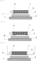
- Fig. 1 illustrates an embodiment of the present invention.
- reference numeral 1 denotes the porous material (B) supporting the transition metal oxide
- reference numeral 2 denotes the porous ceramic support (A)
- reference numeral 3 denotes the solar cell module (C)
- reference numeral 4 denotes the back sheet
- reference numeral 5 denotes the sealing resin layer
- reference numeral 6 denotes a cell
- reference numeral 7 denotes tempered glass, which constitute the solar cell module 3.
- a predetermined gap d is provided between the porous ceramic support 2 and the solar cell module 3.
- cells 6 and the tempered glass 7 are recovered as valuable materials.
- substances, such as a metal and a metal oxide, constituting components such as electrodes and a reflective film are also recovered as valuable materials.
- the surface glass functions as a surface protective material.
- any solar cell module can be utilized as long as it is not of a double-sided glass type and has the resin back sheet 4.
- Specific examples thereof include monocrystalline silicon solar cells, polycrystalline silicon solar cells, amorphous silicon solar cells, heterojunction solar cells, CIS solar cells, CIGS solar cells, and CdTe solar cells.
- the electrodes usually, for example, light-transmissive electrodes, linear electrodes, or ladder-like electrodes or chain-like electrodes on which a metal foil or a metal ribbon serving as a bus bar is stacked are used as the electrodes.
- the metals include silver, copper, and aluminum.
- a transparent electrode containing a conductive oxide as a main component may be provided.
- the conductive oxide it is also possible to use one or more kinds of transparent conductive films selected from the group consisting of an indium tin oxide (ITO), an aluminum-doped zinc oxide (AZO), a boron-doped zinc oxide (BZO), a gallium-doped zinc oxide (GZO), an indium-doped zinc oxide (IZO), an aluminum gallium oxide (AGO), a titanium-doped indium oxide (ITiO), an indium gallium zinc oxide (IGZO), and a hydrogen-doped indium oxide (In 2 O 3 ).
- ITO indium tin oxide
- AZO aluminum-doped zinc oxide
- BZO boron-doped zinc oxide
- GZO gallium-doped zinc oxide
- IZO indium-doped zinc oxide
- AGO aluminum gallium oxide
- ITiO titanium-doped indium oxide
- IGZO indium gallium zinc oxide
- the solar cell module 3 is configured to seal the plurality of cells 6 with the sealing resin layer 5 between the tempered glass 7 and the back sheet 4.
- a thermoplastic resin such as ethylene vinyl acetate (EVA), a polyvinyl butyral resin (PVB), or a polyolefin resin is used.
- EVA ethylene vinyl acetate
- PVB polyvinyl butyral resin
- the cells 6 are sealed by laminating the cells 6 with a sheet made of the sealing resin.
- the sealing resin layer 5 may contain a coloring material such as a white pigment.
- the white pigment such as a titanium oxide has a function of reflecting sunlight to increase light incident on the solar cell module 3.
- Such a white pigment may be kneaded in a sealing resin or a layer containing a white pigment may be stacked to form the sealing resin layer 5.
- the back sheet 4 is a sheet-like back surface protective material, and a base film of EVA or a polyethylene terephthalate resin, a film such as a stacked film of the base film and a weather-resistant fluorine polymer film such as polyvinyl fluoride (PVF) is used.
- a base film of EVA or a polyethylene terephthalate resin a film such as a stacked film of the base film and a weather-resistant fluorine polymer film such as polyvinyl fluoride (PVF) is used.
- PVF polyvinyl fluoride
- an aluminum frame may be attached as a frame in order to protect the peripheral portion of the solar cell module 3.
- the aluminum frame may be removed before thermal decomposition, or may be removed after thermal decomposition in order to reduce the possibility that glass is broken at the time of removal, due to the advantage that it is not necessary to cut the porous ceramic support 2 according to the size of the aluminum frame and the operation becomes simple.
- a reflective film may be provided on the back surface opposite to the sunlight incident surface of the solar cell module as necessary for improving the light receiving efficiency of the cells, and specific examples of the reflective film include a metal film made of metal such as aluminum or silver.
- the solar cell module 3 having the resin back sheet 4 and the sealing resin layer 5 is heated in the pyrolysis furnace to melt and oxidatively decompose the resin component included in the solar cell module 3.
- This oxidative decomposition usually involves combustion of the resin component.
- the solar cell module 3 is placed above the porous ceramic support 2 with a predetermined gap therebetween, and the porous ceramic support 2 is moved in the furnace from the inlet toward the outlet of the pyrolysis furnace in a state of being placed on the porous material 1 supporting the transition metal oxide.
- hot air is blown from the porous material 1 side.
- the hot air passes through pores of the porous material 1 and the porous ceramic support 2, reaches the gap with the solar cell module 3, collides with the solar cell module 3, and diffuses into the gap d.
- the object to be processed may be put into, for example, an iron lattice tray in order to prevent the solar cell module 3, the porous ceramic support 2, and the porous material 1 from being misaligned or being turned over in a movement in the furnace.
- the gap d can be provided, for example, by installing a spacer member 8 between the porous ceramic support 2 and the solar cell module 3 as illustrated in Fig. 2 , or by installing a lifting member 9 for lifting the solar cell module 3 at an upper part of the pyrolysis furnace as illustrated in Fig. 3 .
- the shape and form of the spacer member 8 are not particularly limited as long as a predetermined gap can be provided, and may be, for example, a lattice type, a sphere, a rod, or another type, and the spacer member 8 may be placed on the porous ceramic support 2 such that the solar cell module 3 does not bend.
- the lifting member 9 is not particularly limited as long as it is configured to lift the solar cell module 3 from above, and a material such as a basket material can also be used. These members are usually made of a refractory material that does not deform or react during heating, and are made of, for example, an inorganic material such as stainless steel, silica, or alumina.
- the gap d between the solar cell module 3 and the porous ceramic support 2 is preferably in a range of 3 to 50 mm, preferably 4 to 40 mm, and more preferably 5 to 15 mm.
- the gap d is selected within the above range according to the air permeability of the porous ceramic support 2 and the porous material 1 and the amount of hot air to be sent. It is to be noted that "to” represents not falling below and not exceeding unless otherwise specified.
- Resin components such as EVA and PET, constituting the back sheet 4 and the sealing resin layer 5 are melted during the heating step, and then flow out toward the porous ceramic support 2 by the action of gravity.
- the porous ceramic support 2 is porous, the resin components that have been melted and flowed down have a large contact area with the atmosphere in the heating furnace, and can capture components such as a white pigment contained as a solid content.
- the resin components that have been melted and flowed down pass through the porous ceramic support 2, reach the porous material 1, are oxidatively decomposed by the supported transition metal oxide, and the decomposed components are combusted. With this configuration, it is possible to suppress the generation of "soot".
- the atmosphere in the heating furnace in the heating step is desirably controlled to have an oxygen concentration of 6 vol% or more and less than 15 vol%.
- the resin components can be gently and stably combusted and removed, which is desirable.
- the temperature of the pyrolysis furnace is appropriately determined according to the resin constituting the back sheet 4 and the sealing resin layer 5, and is preferably in a range of 425 to 575°C.
- the temperature is 425°C or higher, the temperature is higher than the thermal decomposition temperature of the resin used for the back sheet 4 and the sealing resin layer 5, and the combustion occurs.
- the temperature is 575°C or lower, rapid combustion can be suppressed, and the glass of the solar cell module 3 can be prevented from being damaged.
- the pyrolysis furnace is not particularly limited as long as it is a pyrolysis furnace, such as a gas furnace or an electric furnace, that enables the above-described temperature to be obtained, and into which the object to be processed including the porous material 1, the porous ceramic support 2, and the solar cell module 3 can be loaded, and a known pyrolysis furnace can be used.
- a pyrolysis furnace such as a gas furnace or an electric furnace, that enables the above-described temperature to be obtained, and into which the object to be processed including the porous material 1, the porous ceramic support 2, and the solar cell module 3 can be loaded, and a known pyrolysis furnace can be used.
- Examples of a method of sending hot air include a method of heating an oxygen-containing gas with a burner such as a gas burner and sending the gas from the porous material 1 side.
- a burner such as a gas burner
- sending the gas from the porous material 1 side are not particularly limited as long as the temperature in the furnace can be obtained, for example, in the case of a gas furnace, the entire inside of the furnace may be heated together with air supply in this case.
- a valuable material that remains on the porous ceramic support 2 be recovered.
- the valuable material is at least one selected from the group consisting of the glass, the cells, a conductive material used for the electrodes, the aluminum frame, and another material.
- a network structure for preventing falling may be installed under the solar cell module (C).
- a network structure such as a wire mesh is installed between the solar cell module 3 and the porous ceramic support 2, and the remaining valuable material is recovered together with the wire mesh even if the resin is melted and moves onto the porous ceramic support 2.
- the valuable material can be efficiently recovered without disassembly of the glass, the cells, and other materials.
- the porous ceramic support 2 applicable to the present invention can be used without any limitation as long as it is stable at the above-described temperature (specifically, about 425°C to 575°C) and has a porous structure.
- Specific examples of the material thereof include stable and common ceramic materials such as alumina, zirconia, silicon nitride, silicon carbide, cordierite, ferrite, barium titanate, lead zirconate titanate, forsterite, zircon, mullite, steatite, and aluminum nitride.
- the pore size of the porous ceramic support 2 is not particularly limited, but is preferably about 0.1 to 5 mm such that EVA, PET and another component easily permeate into the porous ceramic support 2 when they are melted at around 450°C.
- the number of cells on the surface is not particularly limited, either, but is desirably in a range of 5 to 50 pixels per inch (hereinafter abbreviated as "ppi").
- the porosity is not limited at all, but is desirably about 50 to 95%. In particular, one having a three-dimensional skeleton structure with continuous pores can be suitably used.
- the shape of the porous ceramic support 2 is not particularly limited, but in order to prevent the resin used in the solar cell module 3 from falling from the porous ceramic support 2, a plate-shaped one can be suitably used. Furthermore, from the viewpoint that the generation of "soot" due to leakage of a melted resin component to the outside of the porous ceramic support 2 can be suppressed, the size (area) of the surface of the porous ceramic support 2 above which the back sheet 4 is placed is preferably as large as possible within the range that the surface can fit in the aluminum frame in a case where the aluminum frame is not removed, and in a case where the aluminum frame is removed from the solar cell module 3, it is preferably larger than the bottom area of the back sheet 4.
- the thickness of the porous ceramic support 2 there is no limitation on the thickness of the porous ceramic support 2, but one having a thickness of about 10 to 60 mm is suitable.
- porous ceramic support 2 As the porous ceramic support 2 as described above, a product, which is called a ceramic foam, a ceramic filter, or a ceramic foam filter that is made of alumina, silicon carbide, and cordierite, is suitable.
- the solar cell module 3 is placed above the porous ceramic support 2 with the back sheet 4 surface facing downward.
- the resin components constituting the back sheet 4 and the sealing resin layer 5 are melted due to heating, and then flow out toward the porous ceramic support 2 due to the action of gravity.
- the porous ceramic support 2 is porous, the resin that has flowed down has a large contact area with the atmosphere in the pyrolysis furnace. Therefore, the efficiency of combustion by further heating increases, and the generation of "soot" can be suppressed.
- the transition metal oxide has an ability to adsorb oxygen in the oxidized state and to decompose an organic compound containing an aromatic ring that has been produced by oxidatively decomposing an aromatic resin during combustion.
- the generation of "soot" can be suppressed.
- preferable examples include oxides of first transition elements including scandium, titanium, vanadium, chromium, manganese, iron, cobalt, nickel, and copper; oxides of second transition elements including yttrium, zirconium, niobium, molybdenum, technetium, ruthenium, rhodium, palladium, and silver; and oxides of third transition elements including lanthanum, cerium, praseodymium, neodymium, promethium, samarium, europium, gadolinium, terbium, dysprosium, holmium, erbium, thulium, ytterbium, lutetium, hafnium, tantalum, tungsten, rhenium, osmium, iridium, platinum, and gold, and more preferably, transition metal oxides such as a rutile or anatase type titanium (IV) oxide, a chromium (III) oxide,
- the porous material 1 may be any material as long as it is stable at the combustion temperature of the resin component as with the porous ceramic support 2, and examples thereof include the same materials.
- the shape of the porous material 1 is not particularly limited, and is not particularly limited as long as it can be a so-called catalyst carrier.
- the porous material 1 is more preferably a plate-shaped porous molded body that is similar to the porous ceramic support 2 above which the solar cell module 3 is placed.
- a known technique can be used without any limitations. Specifically, a method of impregnating the porous material 1 in a solution containing the transition metal oxide by using, for example, dip coating, wash coating, spray coating, or spin coating, and having the porous material 1 support the transition metal oxide is common. After that, the solution is removed by heating the porous material to the boiling point of the solution or higher. This is the simplest method. Alternatively, a thermal spraying technique in which the melted transition metal oxide is sprayed onto the porous material 1 may be utilized.
- the porous ceramic support 2 is placed on the porous material 1 supporting the transition metal oxide.
- a loading surface of the porous material 1 have an area that is similar to the bottom area of the porous ceramic support 2.
- the thickness of the porous material 1 is suitably about 10 to 60 mm.
- the number of cells on the surface of the porous material 1 is preferably in a range of 5 to 50 pixels per inch (hereinafter abbreviated as "ppi").
- the porosity is not limited at all, but is desirably about 50 to 95% as with the porous ceramic support 2.
- one having a three-dimensional skeleton structure with continuous pores can be suitably used.
- a shelf board used in the present invention may have any aspect as long as it has heat resistance and the loaded solar cell module 3, porous ceramic support 2, and porous material 1 can be heated, and examples thereof include ceramic shelf boards and SUS wire meshes.
- a polycrystalline silicon solar cell "KD270HX-BPEFMS" manufactured by KYOCERA Corporation was used for evaluation.
- the electrodes and the aluminum frame on the back sheet 4 were removed before the heat treatment step.
- a ceramic filter that serves as the porous ceramic support 2 and has 10 ppi and 300 mm ⁇ 400 mm ⁇ 15 mmt (product of Nippon Crucible Co., Ltd. (material: silicon carbide)) was used (this is referred to as a porous ceramic support (A-1)).
- a ceramic filter product of Nippon Crucible Co., Ltd. (material: silicon carbide)
- 10 ppi and 300 mm ⁇ 400 mm ⁇ 45 mmt was used as the porous material 1 supporting the catalyst.
- a chromium (III) oxide (manufactured by FUJIFILM Wako Pure Chemical Corporation) was stirred while being suspended in water on this ceramic filter, and the ceramic filter was immersed to perform dip coating, and was dried at 450°C to prepare a chromium-supported porous material (B-1).
- the mass of the chromium-supported porous material (B-1) was 2300 g before the coating and was 2859 g after the coating and the drying.
- An iron tray having a grid-like bottom of 2,100 mm ⁇ 1,210 mm ⁇ 50 mm was manufactured, and this chromium-supported porous material (B-1) was placed.
- the porous ceramic support (A-1) was placed thereon.
- a stainless steel lattice spacer (interval between grids: 160 mm, height: 10 mm) as the spacer member 8 was placed on the porous ceramic support (A-1) to provide a predetermined interval, and the solar cell module 3 was placed on the lattice spacer such that the back sheet 4 was on the lower side.
- a gas furnace was used as the pyrolysis furnace.
- a hot air circulation type heat treatment device of a cyclically fed chain-blow type that has a furnace length of 5,400 mm, a furnace width of 2,300 mm, and a furnace height of 280 mm was used.
- a gas burner unit a metallic burner MJPE-200K was used to burn and heat a mixed gas of LP gas and air.
- the heated mixed gas was supplied by squeezing with a slit from the lower side of the pyrolysis furnace section using "6.0-LF limit load fan" (450 m 3 /min, 2.0 kPa, 30 kw) made by ADACHI KIKO CO., LTD., and vigorously blown against the chromium-supported porous material (B-1) to supply hot air.
- the oxygen concentration in the pyrolysis furnace was controlled in a range of 6 vol% or more and less than 15 vol%.
- the temperature in the furnace was controlled to 490°C, and the heat treatment was performed for 20 minutes. Changes in the temperature in the furnace were evaluated at the temperature of the center under the back sheet 4 of the solar cell module 3.
- Example 2 The same heat treatment as in Example 1 was performed using a stainless steel lattice spacer having a lattice interval of 160 mm and a height of 20 mm as the spacer member 8 instead of the stainless steel lattice spacer used in Example 1.
- Example 2 The same heat treatment as in Example 1 was performed using a stainless steel lattice spacer having a lattice interval of 160 mm and a height of 30 mm instead of the stainless steel lattice spacer used in Example 1.
- Example 2 The same heat treatment as in Example 1 was performed except that a stainless steel lattice spacer was not used.
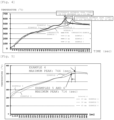
- Fig. 4 illustrates changes in temperature in the furnace with respect to the heating time in the heat treatment in Examples 1 to 3 and Comparative Example 1.
- Example 1 as the porous ceramic support 2, a ceramic filter (material: silicon carbide) with 7 ppi and 300 mm ⁇ 400 mm ⁇ 15 mmt manufactured by Nippon Crucible Co., Ltd. was used (this is referred to as a porous ceramic support (A-2)).
- a chromium-supported porous material (B-2) was prepared using a ceramic filter (product of Nippon Crucible Co., Ltd. (material: silicon carbide)) with 7 ppi and 300 mm ⁇ 400 mm ⁇ 45 mmt and using a chromium (III) oxide in the same manner as in Example 1.
- the mass of the chromium-supported porous material (B-2) was 2300 g before the coating and was 2859 g after the coating and the drying.
- the chromium-supported porous material (B-2) and the porous ceramic support (A-2) were placed in the same manner as in Example 1. Further, a stainless steel lattice spacer (interval between grids: 160 mm, height: 10 mm) as the spacer member 8 was placed on the porous ceramic support (A-2) to provide a predetermined interval, and the solar cell module 3 was placed on the lattice spacer such that the back sheet 4 was on the lower side.
- a gas furnace was used as the pyrolysis furnace.
- the gas was supplied by squeezing with a slit from the lower side of the pyrolysis furnace section used in Example 1, and vigorously blown against the chromium-supported porous material (B-2) to supply hot air. Without controlling the oxygen concentration in the pyrolysis furnace, the temperature in the furnace was controlled to 500°C, and the heat treatment was performed for 15 minutes.
- Example 4 The same heat treatment as in Example 4 was performed using a stainless steel lattice spacer (having a lattice interval of 160 mm and a height of 30 mm) as the spacer member 8 instead of the stainless steel lattice spacer used in Example 4.
- a stainless steel lattice spacer having a lattice interval of 160 mm and a height of 30 mm
- Example 4 The same heat treatment as in Example 4 was performed using a stainless steel lattice spacer (having a lattice interval of 160 mm and a height of 40 mm) as the spacer member 8 instead of the stainless steel lattice spacer used in Example 4.
- a stainless steel lattice spacer having a lattice interval of 160 mm and a height of 40 mm
- Fig. 5 illustrates changes in temperature with respect to heating time in a heating step in Examples 4 to 6.
- Example 4 in which the gap was 10 mm, the time at which the peak became maximum was earlier by 30 seconds than in Examples 4 and 5. Changes when the gaps of 30 mm and 40 mm are provided are the same, and it is considered that the changes are the same even if the gap is further increased.
Landscapes
- Physics & Mathematics (AREA)
- Thermal Sciences (AREA)
- Chemical & Material Sciences (AREA)
- Engineering & Computer Science (AREA)
- Environmental & Geological Engineering (AREA)
- Health & Medical Sciences (AREA)
- Sustainable Development (AREA)
- Life Sciences & Earth Sciences (AREA)
- Chemical Kinetics & Catalysis (AREA)
- Medicinal Chemistry (AREA)
- Polymers & Plastics (AREA)
- Organic Chemistry (AREA)
- Photovoltaic Devices (AREA)
- Processing Of Solid Wastes (AREA)
- Separation, Recovery Or Treatment Of Waste Materials Containing Plastics (AREA)
Abstract
Description
- The present invention relates to a method for processing a waste solar cell. More specifically, the present invention relates to a processing method for efficiently removing resin components such as a back sheet and a sealing resin layer from a solar cell module, and recovering valuable materials such as a conductive material and an aluminum frame derived from glass, cells, and electrodes.
- Toward the realization of a low-carbon society, the acceleration of CO2 reduction by utilizing renewable energy such as solar power generation is about to progress. While the introduction of solar power generation has progressed significantly, problems of recycling at the time of disposal of solar cell modules have been pointed out.
- The structure of a general solar cell module has three layers, tempered glass on the front surface, a sealing resin layer on the inside, and a back sheet on the back surface. An electric wire (interconnector) connecting cells is wired in the sealing resin layer. The sealing resin is required to have properties such as transparency, flexibility, adhesiveness, tensile strength, and weather resistance, and an ethylene-vinyl acetate copolymer (hereinafter abbreviated as "EVA") is generally used as the sealing resin. The sealing resin serves to bond the tempered glass, the cells, and the back sheet by heating and pressurizing.
- There has been proposed a technique for recycling a solar cell module by heating the solar cell module by a furnace such as an electric furnace under an oxidizing atmosphere to thermally decompose EVA to remove a sealing material and separate a cell section and a glass substrate.
- The present applicant has also proposed a processing method for recovering a valuable material from a solar cell module, in which the solar cell module is placed on a porous molded body made of a heat-resistant material supporting a transition metal oxide as a catalyst with a back sheet surface facing downward, the solar cell module is heated in a heating furnace under an oxidizing atmosphere having an oxygen concentration of 15% or more to melt a resin component, and then the resin component is combusted (see Patent Literature 1).
- Patent Literature 1:
WO 2020/031661 A - When the entire module is heated on the porous molded body as in
Patent Literature 1, there is a problem that the processing time is prolonged because the temperature rise is moderate. On the other hand, in order to reduce the processing cost, it is efficient to increase the number of sheets to be processed per unit time, and it is necessary to shorten the processing time. However, when the processing speed is increased by increasing the temperature in a pyrolysis furnace, there arises a new problem that the cost such as fuel cost is increased. - The present inventors have conducted diligent studies to solve the above problems. As a result, the present inventors have found that when an entire module is heated above a porous molded body, a predetermined gap is provided between the porous molded body and the module, and hot air is sent from a lower portion of the porous molded body, so that it is possible to speed up a temperature rise of the entire module, improve a processing speed, and shorten a processing time, thereby completing the present invention.
- That is, configurations of the present invention are as follows.
- [1] A method for continuously processing a waste solar cell, the method including a heating step of heating a solar cell module (C) including a resin back sheet and a sealing resin layer in a pyrolysis furnace to melt and oxidatively decompose a resin component included in the solar cell module (C), wherein
in the heating step, in a state in which the solar cell module (C) is placed above a porous ceramic support (A) so as to be separated from the porous ceramic support (A), and the porous ceramic support (A) is stacked on a porous material (B) supporting a transition metal oxide, hot air is sent from a porous material (B) side to insides of the porous material (B) and the porous ceramic support (A) and to a gap between the solar cell module (C) and the porous ceramic support (A). - [2] The method for processing a waste solar cell according to [1], wherein the solar cell module (C) and the porous ceramic support (A) are separated from each other by installing a spacer member between the porous ceramic support (A) and the solar cell module (C) or installing, at an upper part of the pyrolysis furnace, a lifting member for lifting the solar cell module (C).
- [3] The method for processing a waste solar cell according to [1] or [2], wherein the gap between the solar cell module (C) and the porous ceramic support (A) is in a range of 3 to 50 mm.
- [4] The method for processing a waste solar cell according to any one of [1] to [3], wherein the number of cells on each of surfaces of the porous ceramic support (A) and the porous material (B) is in a range of 5 to 50 pixels per inch (hereinafter abbreviated as "ppi").
- [5] The method for processing a waste solar cell according to any one of [1] to [4], wherein a network structure for preventing falling is installed under the solar cell module (C).
- [6] The method for processing a waste solar cell according to any one of [1] to [5], wherein a valuable material is recovered after the heating step.
- In the present invention, since heat can be efficiently transferred, the speed at which a waste solar cell is processed can be improved, the processing time can be shortened, and a reusable valuable material can be efficiently recovered.
-
-
Fig. 1 is a schematic diagram illustrating one embodiment of the present invention. -
Fig. 2 is a schematic diagram illustrating another embodiment of the present invention. -
Fig. 3 is a schematic diagram illustrating still another embodiment of the present invention. -
Fig. 4 is a graph illustrating changes in temperature at the center under a back sheet of a solar cell module in Examples 1 to 3 and Comparative Example 1. -
Fig. 5 is a graph illustrating changes in temperature at the center under a back sheet of a solar cell module in Examples 4 to 6. - Hereinafter, the present invention will be described in detail.
- A method for processing a waste solar cell according to the present invention is a method for continuously processing a waste solar cell, the method including a heating step of heating a solar cell module (C) including a resin back sheet and a sealing resin layer in a pyrolysis furnace to melt and oxidatively decompose a resin component included in the solar cell module (C).
- In the heating step, in a state in which the solar cell module (C) is placed above a porous ceramic support (A) so as to be separated from the porous ceramic support (A), and the porous ceramic support (A) is stacked on a porous material (B) supporting a transition metal oxide, hot air is sent from a porous material (B) side to insides of the porous material (B) and the porous ceramic support (A) and to a gap between the solar cell module (C) and the porous ceramic support (A).
-
Fig. 1 illustrates an embodiment of the present invention. InFig. 1 ,reference numeral 1 denotes the porous material (B) supporting the transition metal oxide,reference numeral 2 denotes the porous ceramic support (A), andreference numeral 3 denotes the solar cell module (C), whilereference numeral 4 denotes the back sheet,reference numeral 5 denotes the sealing resin layer,reference numeral 6 denotes a cell, andreference numeral 7 denotes tempered glass, which constitute thesolar cell module 3. A predetermined gap d is provided between the porousceramic support 2 and thesolar cell module 3. In one aspect of the present invention,cells 6 and thetempered glass 7 are recovered as valuable materials. Although not illustrated, substances, such as a metal and a metal oxide, constituting components such as electrodes and a reflective film are also recovered as valuable materials. The surface glass functions as a surface protective material. - As the
solar cell module 3 applicable to the present invention, any solar cell module can be utilized as long as it is not of a double-sided glass type and has theresin back sheet 4. Specific examples thereof include monocrystalline silicon solar cells, polycrystalline silicon solar cells, amorphous silicon solar cells, heterojunction solar cells, CIS solar cells, CIGS solar cells, and CdTe solar cells. - In the
solar cell module 3, although not illustrated, usually, for example, light-transmissive electrodes, linear electrodes, or ladder-like electrodes or chain-like electrodes on which a metal foil or a metal ribbon serving as a bus bar is stacked are used as the electrodes. Examples of the metals include silver, copper, and aluminum. In addition, a transparent electrode containing a conductive oxide as a main component may be provided. As the conductive oxide, it is also possible to use one or more kinds of transparent conductive films selected from the group consisting of an indium tin oxide (ITO), an aluminum-doped zinc oxide (AZO), a boron-doped zinc oxide (BZO), a gallium-doped zinc oxide (GZO), an indium-doped zinc oxide (IZO), an aluminum gallium oxide (AGO), a titanium-doped indium oxide (ITiO), an indium gallium zinc oxide (IGZO), and a hydrogen-doped indium oxide (In2O3). - The
solar cell module 3 is configured to seal the plurality ofcells 6 with the sealingresin layer 5 between thetempered glass 7 and theback sheet 4. As the sealing resin, a thermoplastic resin such as ethylene vinyl acetate (EVA), a polyvinyl butyral resin (PVB), or a polyolefin resin is used. Thecells 6 are sealed by laminating thecells 6 with a sheet made of the sealing resin. The sealingresin layer 5 may contain a coloring material such as a white pigment. The white pigment such as a titanium oxide has a function of reflecting sunlight to increase light incident on thesolar cell module 3. Such a white pigment may be kneaded in a sealing resin or a layer containing a white pigment may be stacked to form thesealing resin layer 5. - The
back sheet 4 is a sheet-like back surface protective material, and a base film of EVA or a polyethylene terephthalate resin, a film such as a stacked film of the base film and a weather-resistant fluorine polymer film such as polyvinyl fluoride (PVF) is used. - Furthermore, although not illustrated, an aluminum frame may be attached as a frame in order to protect the peripheral portion of the
solar cell module 3. The aluminum frame may be removed before thermal decomposition, or may be removed after thermal decomposition in order to reduce the possibility that glass is broken at the time of removal, due to the advantage that it is not necessary to cut the porousceramic support 2 according to the size of the aluminum frame and the operation becomes simple. In addition, a reflective film may be provided on the back surface opposite to the sunlight incident surface of the solar cell module as necessary for improving the light receiving efficiency of the cells, and specific examples of the reflective film include a metal film made of metal such as aluminum or silver. - In the heating step in the processing method of the present invention, the
solar cell module 3 having the resin backsheet 4 and the sealingresin layer 5 is heated in the pyrolysis furnace to melt and oxidatively decompose the resin component included in thesolar cell module 3. This oxidative decomposition usually involves combustion of the resin component. - In the heating step, the
solar cell module 3 is placed above the porousceramic support 2 with a predetermined gap therebetween, and the porousceramic support 2 is moved in the furnace from the inlet toward the outlet of the pyrolysis furnace in a state of being placed on theporous material 1 supporting the transition metal oxide. In this case, it is preferable to cause thesolar cell module 3 to face the porousceramic support 2 with theback sheet 4 facing downward from the viewpoint of recovery of materials such as the valuable materials. - In the heating step of the present invention, hot air is blown from the
porous material 1 side. The hot air passes through pores of theporous material 1 and the porousceramic support 2, reaches the gap with thesolar cell module 3, collides with thesolar cell module 3, and diffuses into the gap d. - In addition, in order to increase the processing efficiency, it is preferable to continuously move a plurality of
solar cell modules 3 so that a plurality ofsolar cell modules 3 heated in the pyrolysis furnace are present. Note that in performing heat treatment on an object to be processed including thesolar cell module 3, the porousceramic support 2, and theporous material 1, the object to be processed may be put into, for example, an iron lattice tray in order to prevent thesolar cell module 3, the porousceramic support 2, and theporous material 1 from being misaligned or being turned over in a movement in the furnace. - The gap d can be provided, for example, by installing a
spacer member 8 between the porousceramic support 2 and thesolar cell module 3 as illustrated inFig. 2 , or by installing a liftingmember 9 for lifting thesolar cell module 3 at an upper part of the pyrolysis furnace as illustrated inFig. 3 . - The shape and form of the
spacer member 8 are not particularly limited as long as a predetermined gap can be provided, and may be, for example, a lattice type, a sphere, a rod, or another type, and thespacer member 8 may be placed on the porousceramic support 2 such that thesolar cell module 3 does not bend. - The lifting
member 9 is not particularly limited as long as it is configured to lift thesolar cell module 3 from above, and a material such as a basket material can also be used. These members are usually made of a refractory material that does not deform or react during heating, and are made of, for example, an inorganic material such as stainless steel, silica, or alumina. - The gap d between the
solar cell module 3 and the porousceramic support 2 is preferably in a range of 3 to 50 mm, preferably 4 to 40 mm, and more preferably 5 to 15 mm. The gap d is selected within the above range according to the air permeability of the porousceramic support 2 and theporous material 1 and the amount of hot air to be sent. It is to be noted that "to" represents not falling below and not exceeding unless otherwise specified. - Resin components, such as EVA and PET, constituting the
back sheet 4 and the sealingresin layer 5 are melted during the heating step, and then flow out toward the porousceramic support 2 by the action of gravity. - Since the porous
ceramic support 2 is porous, the resin components that have been melted and flowed down have a large contact area with the atmosphere in the heating furnace, and can capture components such as a white pigment contained as a solid content. - The resin components that have been melted and flowed down pass through the porous
ceramic support 2, reach theporous material 1, are oxidatively decomposed by the supported transition metal oxide, and the decomposed components are combusted. With this configuration, it is possible to suppress the generation of "soot". - For the oxidative decomposition, the atmosphere in the heating furnace in the heating step is desirably controlled to have an oxygen concentration of 6 vol% or more and less than 15 vol%. In this atmosphere, the resin components can be gently and stably combusted and removed, which is desirable.
- The temperature of the pyrolysis furnace is appropriately determined according to the resin constituting the
back sheet 4 and the sealingresin layer 5, and is preferably in a range of 425 to 575°C. When the temperature is 425°C or higher, the temperature is higher than the thermal decomposition temperature of the resin used for theback sheet 4 and the sealingresin layer 5, and the combustion occurs. Furthermore, when the temperature is 575°C or lower, rapid combustion can be suppressed, and the glass of thesolar cell module 3 can be prevented from being damaged. - The pyrolysis furnace is not particularly limited as long as it is a pyrolysis furnace, such as a gas furnace or an electric furnace, that enables the above-described temperature to be obtained, and into which the object to be processed including the
porous material 1, the porousceramic support 2, and thesolar cell module 3 can be loaded, and a known pyrolysis furnace can be used. - Examples of a method of sending hot air include a method of heating an oxygen-containing gas with a burner such as a gas burner and sending the gas from the
porous material 1 side. Although not particularly limited as long as the temperature in the furnace can be obtained, for example, in the case of a gas furnace, the entire inside of the furnace may be heated together with air supply in this case. - In the method according to the present invention, it is preferable that after the heating step, a valuable material that remains on the porous
ceramic support 2 be recovered. The valuable material is at least one selected from the group consisting of the glass, the cells, a conductive material used for the electrodes, the aluminum frame, and another material. - In the method of the present invention, a network structure for preventing falling may be installed under the solar cell module (C). For example, it is also effective that a network structure such as a wire mesh is installed between the
solar cell module 3 and the porousceramic support 2, and the remaining valuable material is recovered together with the wire mesh even if the resin is melted and moves onto the porousceramic support 2. As a result, from the processed object after the resin is melted and combusted, the valuable material can be efficiently recovered without disassembly of the glass, the cells, and other materials. - The porous
ceramic support 2 applicable to the present invention can be used without any limitation as long as it is stable at the above-described temperature (specifically, about 425°C to 575°C) and has a porous structure. Specific examples of the material thereof include stable and common ceramic materials such as alumina, zirconia, silicon nitride, silicon carbide, cordierite, ferrite, barium titanate, lead zirconate titanate, forsterite, zircon, mullite, steatite, and aluminum nitride. - The pore size of the porous
ceramic support 2 is not particularly limited, but is preferably about 0.1 to 5 mm such that EVA, PET and another component easily permeate into the porousceramic support 2 when they are melted at around 450°C. The number of cells on the surface is not particularly limited, either, but is desirably in a range of 5 to 50 pixels per inch (hereinafter abbreviated as "ppi"). The porosity is not limited at all, but is desirably about 50 to 95%. In particular, one having a three-dimensional skeleton structure with continuous pores can be suitably used. - The shape of the porous
ceramic support 2 is not particularly limited, but in order to prevent the resin used in thesolar cell module 3 from falling from the porousceramic support 2, a plate-shaped one can be suitably used. Furthermore, from the viewpoint that the generation of "soot" due to leakage of a melted resin component to the outside of the porousceramic support 2 can be suppressed, the size (area) of the surface of the porousceramic support 2 above which theback sheet 4 is placed is preferably as large as possible within the range that the surface can fit in the aluminum frame in a case where the aluminum frame is not removed, and in a case where the aluminum frame is removed from thesolar cell module 3, it is preferably larger than the bottom area of theback sheet 4. - There is no limitation on the thickness of the porous
ceramic support 2, but one having a thickness of about 10 to 60 mm is suitable. - As the porous
ceramic support 2 as described above, a product, which is called a ceramic foam, a ceramic filter, or a ceramic foam filter that is made of alumina, silicon carbide, and cordierite, is suitable. - In processing the waste solar cell by using the method according to the present invention, the
solar cell module 3 is placed above the porousceramic support 2 with theback sheet 4 surface facing downward. By allowing theback sheet 4 surface to face downward, the resin components constituting theback sheet 4 and the sealingresin layer 5 are melted due to heating, and then flow out toward the porousceramic support 2 due to the action of gravity. - Since the porous
ceramic support 2 is porous, the resin that has flowed down has a large contact area with the atmosphere in the pyrolysis furnace. Therefore, the efficiency of combustion by further heating increases, and the generation of "soot" can be suppressed. - In the
porous material 1 supporting the transition metal oxide that is used in the present invention, the transition metal oxide has an ability to adsorb oxygen in the oxidized state and to decompose an organic compound containing an aromatic ring that has been produced by oxidatively decomposing an aromatic resin during combustion. By using such aporous material 1, the generation of "soot" can be suppressed. - As the transition metal oxide, oxides of, for example, scandium, titanium, vanadium, chromium, manganese, iron, cobalt, nickel, copper, zinc, yttrium, zirconium, niobium, molybdenum, technetium, ruthenium, rhodium, palladium, silver, cadmium, lanthanum, cerium, praseodymium, neodymium, promethium, samarium, europium, gadolinium, terbium, dysprosium, holmium, erbium, thulium, ytterbium, lutetium, hafnium, tantalum, tungsten, rhenium, osmium, iridium, platinum, gold, and mercury can be used without any limitations.
- Among the above, preferable examples include oxides of first transition elements including scandium, titanium, vanadium, chromium, manganese, iron, cobalt, nickel, and copper; oxides of second transition elements including yttrium, zirconium, niobium, molybdenum, technetium, ruthenium, rhodium, palladium, and silver; and oxides of third transition elements including lanthanum, cerium, praseodymium, neodymium, promethium, samarium, europium, gadolinium, terbium, dysprosium, holmium, erbium, thulium, ytterbium, lutetium, hafnium, tantalum, tungsten, rhenium, osmium, iridium, platinum, and gold, and more preferably, transition metal oxides such as a rutile or anatase type titanium (IV) oxide, a chromium (III) oxide, an iron (III) oxide, and a copper (II) oxide can be suitably utilized. These may be in the state of composite oxides.
- The
porous material 1 may be any material as long as it is stable at the combustion temperature of the resin component as with the porousceramic support 2, and examples thereof include the same materials. The shape of theporous material 1 is not particularly limited, and is not particularly limited as long as it can be a so-called catalyst carrier. However, theporous material 1 is more preferably a plate-shaped porous molded body that is similar to the porousceramic support 2 above which thesolar cell module 3 is placed. - As a method of having the
porous material 1 support the transition metal oxide, a known technique can be used without any limitations. Specifically, a method of impregnating theporous material 1 in a solution containing the transition metal oxide by using, for example, dip coating, wash coating, spray coating, or spin coating, and having theporous material 1 support the transition metal oxide is common. After that, the solution is removed by heating the porous material to the boiling point of the solution or higher. This is the simplest method. Alternatively, a thermal spraying technique in which the melted transition metal oxide is sprayed onto theporous material 1 may be utilized. - In the present invention, the porous
ceramic support 2 is placed on theporous material 1 supporting the transition metal oxide. - As the size of the
porous material 1, from the viewpoint of stability of the object to be processed including thesolar cell module 3, it is preferable that a loading surface of theporous material 1 have an area that is similar to the bottom area of the porousceramic support 2. The thickness of theporous material 1 is suitably about 10 to 60 mm. Similarly to the porousceramic support 2, the number of cells on the surface of theporous material 1 is preferably in a range of 5 to 50 pixels per inch (hereinafter abbreviated as "ppi"). The porosity is not limited at all, but is desirably about 50 to 95% as with the porousceramic support 2. - In particular, one having a three-dimensional skeleton structure with continuous pores can be suitably used.
- Hereinafter, embodiments of a recovery method of the present invention will be described with reference to Examples, but the present invention is not limited to the following embodiments and examples, and can be arbitrarily changed and implemented without departing from the gist of the present invention.
- A shelf board used in the present invention may have any aspect as long as it has heat resistance and the loaded
solar cell module 3, porousceramic support 2, andporous material 1 can be heated, and examples thereof include ceramic shelf boards and SUS wire meshes. - As the
solar cell module 3, a polycrystalline silicon solar cell "KD270HX-BPEFMS" manufactured by KYOCERA Corporation was used for evaluation. The electrodes and the aluminum frame on theback sheet 4 were removed before the heat treatment step. - A ceramic filter that serves as the porous
ceramic support 2 and has 10 ppi and 300 mm × 400 mm × 15 mmt (product of Nippon Crucible Co., Ltd. (material: silicon carbide)) was used (this is referred to as a porous ceramic support (A-1)). - As the
porous material 1 supporting the catalyst, a ceramic filter (product of Nippon Crucible Co., Ltd. (material: silicon carbide)) with 10 ppi and 300 mm × 400 mm × 45 mmt was used. A chromium (III) oxide (manufactured by FUJIFILM Wako Pure Chemical Corporation) was stirred while being suspended in water on this ceramic filter, and the ceramic filter was immersed to perform dip coating, and was dried at 450°C to prepare a chromium-supported porous material (B-1). The mass of the chromium-supported porous material (B-1) was 2300 g before the coating and was 2859 g after the coating and the drying. - An iron tray having a grid-like bottom of 2,100 mm × 1,210 mm × 50 mm was manufactured, and this chromium-supported porous material (B-1) was placed. The porous ceramic support (A-1) was placed thereon. Further, a stainless steel lattice spacer (interval between grids: 160 mm, height: 10 mm) as the
spacer member 8 was placed on the porous ceramic support (A-1) to provide a predetermined interval, and thesolar cell module 3 was placed on the lattice spacer such that theback sheet 4 was on the lower side. - A gas furnace was used as the pyrolysis furnace. As the gas furnace, a hot air circulation type heat treatment device of a cyclically fed chain-blow type that has a furnace length of 5,400 mm, a furnace width of 2,300 mm, and a furnace height of 280 mm was used. As a gas burner unit, a metallic burner MJPE-200K was used to burn and heat a mixed gas of LP gas and air. The heated mixed gas was supplied by squeezing with a slit from the lower side of the pyrolysis furnace section using "6.0-LF limit load fan" (450 m3/min, 2.0 kPa, 30 kw) made by ADACHI KIKO CO., LTD., and vigorously blown against the chromium-supported porous material (B-1) to supply hot air. The oxygen concentration in the pyrolysis furnace was controlled in a range of 6 vol% or more and less than 15 vol%. The temperature in the furnace was controlled to 490°C, and the heat treatment was performed for 20 minutes. Changes in the temperature in the furnace were evaluated at the temperature of the center under the
back sheet 4 of thesolar cell module 3. - The same heat treatment as in Example 1 was performed using a stainless steel lattice spacer having a lattice interval of 160 mm and a height of 20 mm as the
spacer member 8 instead of the stainless steel lattice spacer used in Example 1. - The same heat treatment as in Example 1 was performed using a stainless steel lattice spacer having a lattice interval of 160 mm and a height of 30 mm instead of the stainless steel lattice spacer used in Example 1.
- The same heat treatment as in Example 1 was performed except that a stainless steel lattice spacer was not used.
-
Fig. 4 illustrates changes in temperature in the furnace with respect to the heating time in the heat treatment in Examples 1 to 3 and Comparative Example 1. - In all of Examples, peaks of the temperature in the furnace caused by combustion were observed. However, when differences between peak times in Examples 1 to 3 in which the predetermined gap was provided and a peak time in Comparative Example 1 in which no gap was provided were evaluated, it was found that the time at which a peak occurred in the temperature in the furnace in each of Examples was earlier than that in Comparative Example 1. Specifically, the peak time in Example 1 was earlier by 126 seconds than that in Comparative Example 1, the peak time in Examples 2 and 3 was earlier by 104 seconds than that in Comparative Example 1 in which no gap was provided, and it was found that heating was completed in a short time and that the processing efficiency was high.
- In Example 1, as the porous
ceramic support 2, a ceramic filter (material: silicon carbide) with 7 ppi and 300 mm × 400 mm × 15 mmt manufactured by Nippon Crucible Co., Ltd. was used (this is referred to as a porous ceramic support (A-2)). - As the
porous material 1 supporting the catalyst, a chromium-supported porous material (B-2) was prepared using a ceramic filter (product of Nippon Crucible Co., Ltd. (material: silicon carbide)) with 7 ppi and 300 mm × 400 mm × 45 mmt and using a chromium (III) oxide in the same manner as in Example 1. The mass of the chromium-supported porous material (B-2) was 2300 g before the coating and was 2859 g after the coating and the drying. - The chromium-supported porous material (B-2) and the porous ceramic support (A-2) were placed in the same manner as in Example 1. Further, a stainless steel lattice spacer (interval between grids: 160 mm, height: 10 mm) as the
spacer member 8 was placed on the porous ceramic support (A-2) to provide a predetermined interval, and thesolar cell module 3 was placed on the lattice spacer such that theback sheet 4 was on the lower side. - A gas furnace was used as the pyrolysis furnace. The gas was supplied by squeezing with a slit from the lower side of the pyrolysis furnace section used in Example 1, and vigorously blown against the chromium-supported porous material (B-2) to supply hot air. Without controlling the oxygen concentration in the pyrolysis furnace, the temperature in the furnace was controlled to 500°C, and the heat treatment was performed for 15 minutes.
- The same heat treatment as in Example 4 was performed using a stainless steel lattice spacer (having a lattice interval of 160 mm and a height of 30 mm) as the
spacer member 8 instead of the stainless steel lattice spacer used in Example 4. - The same heat treatment as in Example 4 was performed using a stainless steel lattice spacer (having a lattice interval of 160 mm and a height of 40 mm) as the
spacer member 8 instead of the stainless steel lattice spacer used in Example 4. -
Fig. 5 illustrates changes in temperature with respect to heating time in a heating step in Examples 4 to 6. - As a result, it was found that in Example 4 in which the gap was 10 mm, the time at which the peak became maximum was earlier by 30 seconds than in Examples 4 and 5. Changes when the gaps of 30 mm and 40 mm are provided are the same, and it is considered that the changes are the same even if the gap is further increased.
- Based on this, it is considered that even when the interval is increased, the volume of air hitting the solar cell module does not change, and there is no difference in thermal decomposition time, and it has been found that it is highly meaningful to provide an optimal interval.
-
- 1
- porous material
- 2
- porous ceramic support
- 3
- solar cell module
- 4
- back sheet
- 5
- sealing resin layer
- 6
- cell
- 7
- tempered glass
- 8
- spacer member
- 9
- lifting member
Claims (6)
- A method for continuously processing a waste solar cell, the method comprising a heating step of heating a solar cell module (C) including a resin back sheet and a sealing resin layer in a pyrolysis furnace to melt and oxidatively decompose a resin component included in the solar cell module (C), wherein
in the heating step, in a state in which the solar cell module (C) is placed above a porous ceramic support (A) so as to be separated from the porous ceramic support (A), and the porous ceramic support (A) is stacked on a porous material (B) supporting a transition metal oxide, hot air is sent from a porous material (B) side to insides of the porous material (B) and the porous ceramic support (A) and to a gap between the solar cell module (C) and the porous ceramic support (A). - The method for processing a waste solar cell according to claim 1, wherein the solar cell module (C) and the porous ceramic support (A) are separated from each other by installing a spacer member between the porous ceramic support (A) and the solar cell module (C) or installing, at an upper part of the pyrolysis furnace, a lifting member for lifting the solar cell module (C).
- The method for processing a waste solar cell according to claim 1, wherein the gap between the solar cell module (C) and the porous ceramic support (A) is in a range of 3 to 50 mm.
- The method for processing a waste solar cell according to claim 1, wherein the number of cells on each of surfaces of the porous ceramic support (A) and the porous material (B) is in a range of 5 to 50 pixels per inch (hereinafter abbreviated as "ppi").
- The method for processing a waste solar cell according to claim 1, wherein a network structure for preventing falling is installed under the solar cell module (C).
- The method for processing a waste solar cell according to any one of claims 1 to 5, wherein a valuable material is recovered after the heating step.
Applications Claiming Priority (2)
| Application Number | Priority Date | Filing Date | Title |
|---|---|---|---|
| JP2021185122A JP2023072515A (en) | 2021-11-12 | 2021-11-12 | Method for treating waste solar cell |
| PCT/JP2022/041301 WO2023085220A1 (en) | 2021-11-12 | 2022-11-07 | Waste solar cell processing method |
Publications (2)
| Publication Number | Publication Date |
|---|---|
| EP4431556A1 true EP4431556A1 (en) | 2024-09-18 |
| EP4431556A4 EP4431556A4 (en) | 2025-10-29 |
Family
ID=86336046
Family Applications (1)
| Application Number | Title | Priority Date | Filing Date |
|---|---|---|---|
| EP22892719.0A Pending EP4431556A4 (en) | 2021-11-12 | 2022-11-07 | METHOD FOR PROCESSING WASTE SOLAR CELLS |
Country Status (7)
| Country | Link |
|---|---|
| US (1) | US20250229309A1 (en) |
| EP (1) | EP4431556A4 (en) |
| JP (1) | JP2023072515A (en) |
| KR (1) | KR20240110552A (en) |
| CN (1) | CN117651617A (en) |
| AU (1) | AU2022386880A1 (en) |
| WO (1) | WO2023085220A1 (en) |
Family Cites Families (14)
| Publication number | Priority date | Publication date | Assignee | Title |
|---|---|---|---|---|
| US7935912B2 (en) * | 2004-05-27 | 2011-05-03 | Kyocera Corporation | Ceramic heater, and glow plug using the same |
| CN101719529B (en) * | 2009-11-17 | 2011-07-06 | 广东金刚玻璃科技股份有限公司 | Method for recovering crystalline silicon cell plate in double-glass solar cell assembly with PVB interbed |
| JP5904487B2 (en) * | 2012-01-17 | 2016-04-13 | 国立大学法人信州大学 | Processing method and processing apparatus for plastic or plastic composite material |
| JP6596735B2 (en) * | 2014-11-10 | 2019-10-30 | 株式会社ジンテク | Method of recovering valuable material from solar cell module and processing device for recovery |
| JP6593585B2 (en) * | 2015-03-17 | 2019-10-23 | 株式会社ジンテク | Method of recovering glass from laminated glass and processing apparatus for recovery |
| JP6596732B2 (en) * | 2015-03-31 | 2019-10-30 | 株式会社ジンテク | Method for recovering valuable material from solar cell panel and processing device for recovery |
| CN206538343U (en) * | 2017-01-19 | 2017-10-03 | 贵州大成玻璃工程有限责任公司 | A kind of glass toughening double-chamber furnace |
| EP3834955A4 (en) * | 2018-08-06 | 2022-04-20 | Tokuyama Corporation | METHOD FOR RECOVERING VALUABLES FROM A SOLAR CELL MODULE |
| JP2020142218A (en) * | 2019-03-08 | 2020-09-10 | 株式会社綿谷製作所 | Solar panel disassembly device and solar panel disassembly method |
| CN113748299B (en) * | 2019-04-26 | 2025-01-28 | 新见太阳能股份有限公司 | Thermal decomposition device |
| JP7197909B2 (en) * | 2019-05-21 | 2022-12-28 | 株式会社ジンテク | Method and apparatus for treating mixtures containing various waste polymers, waste metals, and waste organic/inorganic substances |
| US11931783B2 (en) * | 2019-11-08 | 2024-03-19 | Industrial Technology Research Institute | Recycle apparatus for photovoltaic module |
| JP7329421B2 (en) * | 2019-11-14 | 2023-08-18 | 株式会社トクヤマ | Waste solar panel processing method and processing system |
| US20220194842A1 (en) * | 2020-12-23 | 2022-06-23 | Yong Su LEE | Waste glass recovery method for manufacturing glass bead |
-
2021
- 2021-11-12 JP JP2021185122A patent/JP2023072515A/en active Pending
-
2022
- 2022-11-07 EP EP22892719.0A patent/EP4431556A4/en active Pending
- 2022-11-07 WO PCT/JP2022/041301 patent/WO2023085220A1/en not_active Ceased
- 2022-11-07 CN CN202280050440.0A patent/CN117651617A/en active Pending
- 2022-11-07 KR KR1020247001310A patent/KR20240110552A/en active Pending
- 2022-11-07 US US18/704,481 patent/US20250229309A1/en active Pending
- 2022-11-07 AU AU2022386880A patent/AU2022386880A1/en active Pending
Also Published As
| Publication number | Publication date |
|---|---|
| CN117651617A (en) | 2024-03-05 |
| AU2022386880A1 (en) | 2024-02-08 |
| WO2023085220A1 (en) | 2023-05-19 |
| KR20240110552A (en) | 2024-07-15 |
| US20250229309A1 (en) | 2025-07-17 |
| JP2023072515A (en) | 2023-05-24 |
| EP4431556A4 (en) | 2025-10-29 |
Similar Documents
| Publication | Publication Date | Title |
|---|---|---|
| US11908969B2 (en) | Method of recovering valuable materials from photovoltaic module | |
| US12544814B2 (en) | Waste photovoltaic module processing method | |
| JP6596735B2 (en) | Method of recovering valuable material from solar cell module and processing device for recovery | |
| JP6596732B2 (en) | Method for recovering valuable material from solar cell panel and processing device for recovery | |
| US20120037224A1 (en) | Solar battery cell and method of manufacturing the same | |
| CN112086525B (en) | A solar cell and method of making the same | |
| US20250229309A1 (en) | Method for Processing Waste Solar Cell | |
| JP2005311178A (en) | Extraction method of solar cell board material, regenerating method of solar cell, and formation method of ingot for solar cell | |
| CN1841786B (en) | Oxide semiconductor electrode, dye-sensitized solar cell, and method for producing them | |
| Chang et al. | Atmospheric-pressure-plasma-jet particulate TiO2 scattering layer deposition processes for dye-sensitized solar cells | |
| HK40101919A (en) | Waste solar cell processing method | |
| CN102668121A (en) | Solar panels having improved corrosion properties | |
| JPWO2008007448A1 (en) | Dye-sensitized solar cell and electrode and laminated film therefor | |
| CN202695495U (en) | Solar photovoltaic module | |
| HK40082502A (en) | Waste solar cell processing method | |
| HK40082502B (en) | Waste solar cell processing method | |
| EP4659874A1 (en) | Solar cell module recycling system | |
| US20250205762A1 (en) | Solar Cell Module Recycling System and Solar Cell Module Recycling Method | |
| CN223157558U (en) | Perovskite solar cell | |
| KR101486803B1 (en) | Method for disassembling solar cell module | |
| CN203038955U (en) | BIPV solar cell module | |
| Du et al. | Fabricating 43-μm-thick and 12% efficient heterojunction silicon solar cells by using kerfless Si (111) substrates | |
| JP2008010236A (en) | Transparent conductive film and method for forming the same, photoelectric conversion device, and photovoltaic device | |
| KR101650580B1 (en) | Solar cell and method of the manufacturing of the same | |
| JP2009087563A (en) | Laminate for oxide semiconductor electrode, oxide semiconductor electrode, dye-sensitized solar cell, method for producing laminate for oxide semiconductor electrode, and method for producing oxide semiconductor electrode |
Legal Events
| Date | Code | Title | Description |
|---|---|---|---|
| STAA | Information on the status of an ep patent application or granted ep patent |
Free format text: STATUS: THE INTERNATIONAL PUBLICATION HAS BEEN MADE |
|
| PUAI | Public reference made under article 153(3) epc to a published international application that has entered the european phase |
Free format text: ORIGINAL CODE: 0009012 |
|
| STAA | Information on the status of an ep patent application or granted ep patent |
Free format text: STATUS: REQUEST FOR EXAMINATION WAS MADE |
|
| 17P | Request for examination filed |
Effective date: 20240530 |
|
| AK | Designated contracting states |
Kind code of ref document: A1 Designated state(s): AL AT BE BG CH CY CZ DE DK EE ES FI FR GB GR HR HU IE IS IT LI LT LU LV MC ME MK MT NL NO PL PT RO RS SE SI SK SM TR |
|
| DAV | Request for validation of the european patent (deleted) | ||
| DAX | Request for extension of the european patent (deleted) | ||
| A4 | Supplementary search report drawn up and despatched |
Effective date: 20250926 |
|
| RIC1 | Information provided on ipc code assigned before grant |
Ipc: C08J 11/12 20060101AFI20250922BHEP Ipc: B09B 3/40 20220101ALI20250922BHEP Ipc: B09B 101/15 20220101ALN20250922BHEP |