EP4431555A1 - Stretched film and method for modification treatment of stretched film - Google Patents
Stretched film and method for modification treatment of stretched film Download PDFInfo
- Publication number
- EP4431555A1 EP4431555A1 EP22915557.7A EP22915557A EP4431555A1 EP 4431555 A1 EP4431555 A1 EP 4431555A1 EP 22915557 A EP22915557 A EP 22915557A EP 4431555 A1 EP4431555 A1 EP 4431555A1
- Authority
- EP
- European Patent Office
- Prior art keywords
- heat seal
- film
- laser beam
- thickness
- stretched
- Prior art date
- Legal status (The legal status is an assumption and is not a legal conclusion. Google has not performed a legal analysis and makes no representation as to the accuracy of the status listed.)
- Pending
Links
Images



Classifications
-
- B—PERFORMING OPERATIONS; TRANSPORTING
- B29—WORKING OF PLASTICS; WORKING OF SUBSTANCES IN A PLASTIC STATE IN GENERAL
- B29C—SHAPING OR JOINING OF PLASTICS; SHAPING OF MATERIAL IN A PLASTIC STATE, NOT OTHERWISE PROVIDED FOR; AFTER-TREATMENT OF THE SHAPED PRODUCTS, e.g. REPAIRING
- B29C55/00—Shaping by stretching, e.g. drawing through a die; Apparatus therefor
- B29C55/02—Shaping by stretching, e.g. drawing through a die; Apparatus therefor of plates or sheets
-
- B—PERFORMING OPERATIONS; TRANSPORTING
- B23—MACHINE TOOLS; METAL-WORKING NOT OTHERWISE PROVIDED FOR
- B23K—SOLDERING OR UNSOLDERING; WELDING; CLADDING OR PLATING BY SOLDERING OR WELDING; CUTTING BY APPLYING HEAT LOCALLY, e.g. FLAME CUTTING; WORKING BY LASER BEAM
- B23K26/00—Working by laser beam, e.g. welding, cutting or boring
- B23K26/08—Devices involving relative movement between laser beam and workpiece
- B23K26/082—Scanning systems, i.e. devices involving movement of the laser beam relative to the laser head
-
- B—PERFORMING OPERATIONS; TRANSPORTING
- B23—MACHINE TOOLS; METAL-WORKING NOT OTHERWISE PROVIDED FOR
- B23K—SOLDERING OR UNSOLDERING; WELDING; CLADDING OR PLATING BY SOLDERING OR WELDING; CUTTING BY APPLYING HEAT LOCALLY, e.g. FLAME CUTTING; WORKING BY LASER BEAM
- B23K26/00—Working by laser beam, e.g. welding, cutting or boring
- B23K26/20—Bonding
- B23K26/206—Laser sealing
-
- B—PERFORMING OPERATIONS; TRANSPORTING
- B23—MACHINE TOOLS; METAL-WORKING NOT OTHERWISE PROVIDED FOR
- B23K—SOLDERING OR UNSOLDERING; WELDING; CLADDING OR PLATING BY SOLDERING OR WELDING; CUTTING BY APPLYING HEAT LOCALLY, e.g. FLAME CUTTING; WORKING BY LASER BEAM
- B23K26/00—Working by laser beam, e.g. welding, cutting or boring
- B23K26/352—Working by laser beam, e.g. welding, cutting or boring for surface treatment
-
- B—PERFORMING OPERATIONS; TRANSPORTING
- B29—WORKING OF PLASTICS; WORKING OF SUBSTANCES IN A PLASTIC STATE IN GENERAL
- B29C—SHAPING OR JOINING OF PLASTICS; SHAPING OF MATERIAL IN A PLASTIC STATE, NOT OTHERWISE PROVIDED FOR; AFTER-TREATMENT OF THE SHAPED PRODUCTS, e.g. REPAIRING
- B29C55/00—Shaping by stretching, e.g. drawing through a die; Apparatus therefor
- B29C55/02—Shaping by stretching, e.g. drawing through a die; Apparatus therefor of plates or sheets
- B29C55/10—Shaping by stretching, e.g. drawing through a die; Apparatus therefor of plates or sheets multiaxial
- B29C55/12—Shaping by stretching, e.g. drawing through a die; Apparatus therefor of plates or sheets multiaxial biaxial
-
- B—PERFORMING OPERATIONS; TRANSPORTING
- B29—WORKING OF PLASTICS; WORKING OF SUBSTANCES IN A PLASTIC STATE IN GENERAL
- B29C—SHAPING OR JOINING OF PLASTICS; SHAPING OF MATERIAL IN A PLASTIC STATE, NOT OTHERWISE PROVIDED FOR; AFTER-TREATMENT OF THE SHAPED PRODUCTS, e.g. REPAIRING
- B29C55/00—Shaping by stretching, e.g. drawing through a die; Apparatus therefor
- B29C55/02—Shaping by stretching, e.g. drawing through a die; Apparatus therefor of plates or sheets
- B29C55/10—Shaping by stretching, e.g. drawing through a die; Apparatus therefor of plates or sheets multiaxial
- B29C55/12—Shaping by stretching, e.g. drawing through a die; Apparatus therefor of plates or sheets multiaxial biaxial
- B29C55/14—Shaping by stretching, e.g. drawing through a die; Apparatus therefor of plates or sheets multiaxial biaxial successively
- B29C55/143—Shaping by stretching, e.g. drawing through a die; Apparatus therefor of plates or sheets multiaxial biaxial successively firstly parallel to the direction of feed and then transversely thereto
-
- B—PERFORMING OPERATIONS; TRANSPORTING
- B29—WORKING OF PLASTICS; WORKING OF SUBSTANCES IN A PLASTIC STATE IN GENERAL
- B29C—SHAPING OR JOINING OF PLASTICS; SHAPING OF MATERIAL IN A PLASTIC STATE, NOT OTHERWISE PROVIDED FOR; AFTER-TREATMENT OF THE SHAPED PRODUCTS, e.g. REPAIRING
- B29C59/00—Surface shaping of articles, e.g. embossing; Apparatus therefor
- B29C59/16—Surface shaping of articles, e.g. embossing; Apparatus therefor by wave energy or particle radiation, e.g. infrared heating
-
- B—PERFORMING OPERATIONS; TRANSPORTING
- B29—WORKING OF PLASTICS; WORKING OF SUBSTANCES IN A PLASTIC STATE IN GENERAL
- B29C—SHAPING OR JOINING OF PLASTICS; SHAPING OF MATERIAL IN A PLASTIC STATE, NOT OTHERWISE PROVIDED FOR; AFTER-TREATMENT OF THE SHAPED PRODUCTS, e.g. REPAIRING
- B29C65/00—Joining or sealing of preformed parts, e.g. welding of plastics materials; Apparatus therefor
- B29C65/02—Joining or sealing of preformed parts, e.g. welding of plastics materials; Apparatus therefor by heating, with or without pressure
-
- B—PERFORMING OPERATIONS; TRANSPORTING
- B29—WORKING OF PLASTICS; WORKING OF SUBSTANCES IN A PLASTIC STATE IN GENERAL
- B29C—SHAPING OR JOINING OF PLASTICS; SHAPING OF MATERIAL IN A PLASTIC STATE, NOT OTHERWISE PROVIDED FOR; AFTER-TREATMENT OF THE SHAPED PRODUCTS, e.g. REPAIRING
- B29C66/00—General aspects of processes or apparatus for joining preformed parts
- B29C66/01—General aspects dealing with the joint area or with the area to be joined
- B29C66/02—Preparation of the material, in the area to be joined, prior to joining or welding
- B29C66/028—Non-mechanical surface pre-treatments, i.e. by flame treatment, electric discharge treatment, plasma treatment, wave energy or particle radiation
-
- B—PERFORMING OPERATIONS; TRANSPORTING
- B29—WORKING OF PLASTICS; WORKING OF SUBSTANCES IN A PLASTIC STATE IN GENERAL
- B29C—SHAPING OR JOINING OF PLASTICS; SHAPING OF MATERIAL IN A PLASTIC STATE, NOT OTHERWISE PROVIDED FOR; AFTER-TREATMENT OF THE SHAPED PRODUCTS, e.g. REPAIRING
- B29C66/00—General aspects of processes or apparatus for joining preformed parts
- B29C66/01—General aspects dealing with the joint area or with the area to be joined
- B29C66/05—Particular design of joint configurations
- B29C66/10—Particular design of joint configurations particular design of the joint cross-sections
- B29C66/11—Joint cross-sections comprising a single joint-segment, i.e. one of the parts to be joined comprising a single joint-segment in the joint cross-section
- B29C66/112—Single lapped joints
- B29C66/1122—Single lap to lap joints, i.e. overlap joints
-
- B—PERFORMING OPERATIONS; TRANSPORTING
- B29—WORKING OF PLASTICS; WORKING OF SUBSTANCES IN A PLASTIC STATE IN GENERAL
- B29C—SHAPING OR JOINING OF PLASTICS; SHAPING OF MATERIAL IN A PLASTIC STATE, NOT OTHERWISE PROVIDED FOR; AFTER-TREATMENT OF THE SHAPED PRODUCTS, e.g. REPAIRING
- B29C66/00—General aspects of processes or apparatus for joining preformed parts
- B29C66/40—General aspects of joining substantially flat articles, e.g. plates, sheets or web-like materials; Making flat seams in tubular or hollow articles; Joining single elements to substantially flat surfaces
- B29C66/41—Joining substantially flat articles ; Making flat seams in tubular or hollow articles
- B29C66/43—Joining a relatively small portion of the surface of said articles
-
- B—PERFORMING OPERATIONS; TRANSPORTING
- B29—WORKING OF PLASTICS; WORKING OF SUBSTANCES IN A PLASTIC STATE IN GENERAL
- B29C—SHAPING OR JOINING OF PLASTICS; SHAPING OF MATERIAL IN A PLASTIC STATE, NOT OTHERWISE PROVIDED FOR; AFTER-TREATMENT OF THE SHAPED PRODUCTS, e.g. REPAIRING
- B29C66/00—General aspects of processes or apparatus for joining preformed parts
- B29C66/70—General aspects of processes or apparatus for joining preformed parts characterised by the composition, physical properties or the structure of the material of the parts to be joined; Joining with non-plastics material
- B29C66/72—General aspects of processes or apparatus for joining preformed parts characterised by the composition, physical properties or the structure of the material of the parts to be joined; Joining with non-plastics material characterised by the structure of the material of the parts to be joined
- B29C66/723—General aspects of processes or apparatus for joining preformed parts characterised by the composition, physical properties or the structure of the material of the parts to be joined; Joining with non-plastics material characterised by the structure of the material of the parts to be joined being multi-layered
- B29C66/7232—General aspects of processes or apparatus for joining preformed parts characterised by the composition, physical properties or the structure of the material of the parts to be joined; Joining with non-plastics material characterised by the structure of the material of the parts to be joined being multi-layered comprising a non-plastics layer
- B29C66/72321—General aspects of processes or apparatus for joining preformed parts characterised by the composition, physical properties or the structure of the material of the parts to be joined; Joining with non-plastics material characterised by the structure of the material of the parts to be joined being multi-layered comprising a non-plastics layer consisting of metals or their alloys
-
- B—PERFORMING OPERATIONS; TRANSPORTING
- B29—WORKING OF PLASTICS; WORKING OF SUBSTANCES IN A PLASTIC STATE IN GENERAL
- B29C—SHAPING OR JOINING OF PLASTICS; SHAPING OF MATERIAL IN A PLASTIC STATE, NOT OTHERWISE PROVIDED FOR; AFTER-TREATMENT OF THE SHAPED PRODUCTS, e.g. REPAIRING
- B29C66/00—General aspects of processes or apparatus for joining preformed parts
- B29C66/70—General aspects of processes or apparatus for joining preformed parts characterised by the composition, physical properties or the structure of the material of the parts to be joined; Joining with non-plastics material
- B29C66/73—General aspects of processes or apparatus for joining preformed parts characterised by the composition, physical properties or the structure of the material of the parts to be joined; Joining with non-plastics material characterised by the intensive physical properties of the material of the parts to be joined, by the optical properties of the material of the parts to be joined, by the extensive physical properties of the parts to be joined, by the state of the material of the parts to be joined or by the material of the parts to be joined being a thermoplastic or a thermoset
- B29C66/733—General aspects of processes or apparatus for joining preformed parts characterised by the composition, physical properties or the structure of the material of the parts to be joined; Joining with non-plastics material characterised by the intensive physical properties of the material of the parts to be joined, by the optical properties of the material of the parts to be joined, by the extensive physical properties of the parts to be joined, by the state of the material of the parts to be joined or by the material of the parts to be joined being a thermoplastic or a thermoset characterised by the optical properties of the material of the parts to be joined, e.g. fluorescence, phosphorescence
- B29C66/7334—General aspects of processes or apparatus for joining preformed parts characterised by the composition, physical properties or the structure of the material of the parts to be joined; Joining with non-plastics material characterised by the intensive physical properties of the material of the parts to be joined, by the optical properties of the material of the parts to be joined, by the extensive physical properties of the parts to be joined, by the state of the material of the parts to be joined or by the material of the parts to be joined being a thermoplastic or a thermoset characterised by the optical properties of the material of the parts to be joined, e.g. fluorescence, phosphorescence at least one of the parts to be joined being glossy or matt, reflective or refractive
-
- B—PERFORMING OPERATIONS; TRANSPORTING
- B29—WORKING OF PLASTICS; WORKING OF SUBSTANCES IN A PLASTIC STATE IN GENERAL
- B29C—SHAPING OR JOINING OF PLASTICS; SHAPING OF MATERIAL IN A PLASTIC STATE, NOT OTHERWISE PROVIDED FOR; AFTER-TREATMENT OF THE SHAPED PRODUCTS, e.g. REPAIRING
- B29C66/00—General aspects of processes or apparatus for joining preformed parts
- B29C66/70—General aspects of processes or apparatus for joining preformed parts characterised by the composition, physical properties or the structure of the material of the parts to be joined; Joining with non-plastics material
- B29C66/73—General aspects of processes or apparatus for joining preformed parts characterised by the composition, physical properties or the structure of the material of the parts to be joined; Joining with non-plastics material characterised by the intensive physical properties of the material of the parts to be joined, by the optical properties of the material of the parts to be joined, by the extensive physical properties of the parts to be joined, by the state of the material of the parts to be joined or by the material of the parts to be joined being a thermoplastic or a thermoset
- B29C66/737—General aspects of processes or apparatus for joining preformed parts characterised by the composition, physical properties or the structure of the material of the parts to be joined; Joining with non-plastics material characterised by the intensive physical properties of the material of the parts to be joined, by the optical properties of the material of the parts to be joined, by the extensive physical properties of the parts to be joined, by the state of the material of the parts to be joined or by the material of the parts to be joined being a thermoplastic or a thermoset characterised by the state of the material of the parts to be joined
- B29C66/7371—General aspects of processes or apparatus for joining preformed parts characterised by the composition, physical properties or the structure of the material of the parts to be joined; Joining with non-plastics material characterised by the intensive physical properties of the material of the parts to be joined, by the optical properties of the material of the parts to be joined, by the extensive physical properties of the parts to be joined, by the state of the material of the parts to be joined or by the material of the parts to be joined being a thermoplastic or a thermoset characterised by the state of the material of the parts to be joined oriented or heat-shrinkable
- B29C66/73711—General aspects of processes or apparatus for joining preformed parts characterised by the composition, physical properties or the structure of the material of the parts to be joined; Joining with non-plastics material characterised by the intensive physical properties of the material of the parts to be joined, by the optical properties of the material of the parts to be joined, by the extensive physical properties of the parts to be joined, by the state of the material of the parts to be joined or by the material of the parts to be joined being a thermoplastic or a thermoset characterised by the state of the material of the parts to be joined oriented or heat-shrinkable oriented
- B29C66/73713—General aspects of processes or apparatus for joining preformed parts characterised by the composition, physical properties or the structure of the material of the parts to be joined; Joining with non-plastics material characterised by the intensive physical properties of the material of the parts to be joined, by the optical properties of the material of the parts to be joined, by the extensive physical properties of the parts to be joined, by the state of the material of the parts to be joined or by the material of the parts to be joined being a thermoplastic or a thermoset characterised by the state of the material of the parts to be joined oriented or heat-shrinkable oriented bi-axially or multi-axially
-
- B—PERFORMING OPERATIONS; TRANSPORTING
- B29—WORKING OF PLASTICS; WORKING OF SUBSTANCES IN A PLASTIC STATE IN GENERAL
- B29C—SHAPING OR JOINING OF PLASTICS; SHAPING OF MATERIAL IN A PLASTIC STATE, NOT OTHERWISE PROVIDED FOR; AFTER-TREATMENT OF THE SHAPED PRODUCTS, e.g. REPAIRING
- B29C66/00—General aspects of processes or apparatus for joining preformed parts
- B29C66/70—General aspects of processes or apparatus for joining preformed parts characterised by the composition, physical properties or the structure of the material of the parts to be joined; Joining with non-plastics material
- B29C66/73—General aspects of processes or apparatus for joining preformed parts characterised by the composition, physical properties or the structure of the material of the parts to be joined; Joining with non-plastics material characterised by the intensive physical properties of the material of the parts to be joined, by the optical properties of the material of the parts to be joined, by the extensive physical properties of the parts to be joined, by the state of the material of the parts to be joined or by the material of the parts to be joined being a thermoplastic or a thermoset
- B29C66/737—General aspects of processes or apparatus for joining preformed parts characterised by the composition, physical properties or the structure of the material of the parts to be joined; Joining with non-plastics material characterised by the intensive physical properties of the material of the parts to be joined, by the optical properties of the material of the parts to be joined, by the extensive physical properties of the parts to be joined, by the state of the material of the parts to be joined or by the material of the parts to be joined being a thermoplastic or a thermoset characterised by the state of the material of the parts to be joined
- B29C66/7377—General aspects of processes or apparatus for joining preformed parts characterised by the composition, physical properties or the structure of the material of the parts to be joined; Joining with non-plastics material characterised by the intensive physical properties of the material of the parts to be joined, by the optical properties of the material of the parts to be joined, by the extensive physical properties of the parts to be joined, by the state of the material of the parts to be joined or by the material of the parts to be joined being a thermoplastic or a thermoset characterised by the state of the material of the parts to be joined amorphous, semi-crystalline or crystalline
- B29C66/73773—General aspects of processes or apparatus for joining preformed parts characterised by the composition, physical properties or the structure of the material of the parts to be joined; Joining with non-plastics material characterised by the intensive physical properties of the material of the parts to be joined, by the optical properties of the material of the parts to be joined, by the extensive physical properties of the parts to be joined, by the state of the material of the parts to be joined or by the material of the parts to be joined being a thermoplastic or a thermoset characterised by the state of the material of the parts to be joined amorphous, semi-crystalline or crystalline the to-be-joined area of at least one of the parts to be joined being semi-crystalline
-
- B—PERFORMING OPERATIONS; TRANSPORTING
- B29—WORKING OF PLASTICS; WORKING OF SUBSTANCES IN A PLASTIC STATE IN GENERAL
- B29C—SHAPING OR JOINING OF PLASTICS; SHAPING OF MATERIAL IN A PLASTIC STATE, NOT OTHERWISE PROVIDED FOR; AFTER-TREATMENT OF THE SHAPED PRODUCTS, e.g. REPAIRING
- B29C66/00—General aspects of processes or apparatus for joining preformed parts
- B29C66/70—General aspects of processes or apparatus for joining preformed parts characterised by the composition, physical properties or the structure of the material of the parts to be joined; Joining with non-plastics material
- B29C66/73—General aspects of processes or apparatus for joining preformed parts characterised by the composition, physical properties or the structure of the material of the parts to be joined; Joining with non-plastics material characterised by the intensive physical properties of the material of the parts to be joined, by the optical properties of the material of the parts to be joined, by the extensive physical properties of the parts to be joined, by the state of the material of the parts to be joined or by the material of the parts to be joined being a thermoplastic or a thermoset
- B29C66/739—General aspects of processes or apparatus for joining preformed parts characterised by the composition, physical properties or the structure of the material of the parts to be joined; Joining with non-plastics material characterised by the intensive physical properties of the material of the parts to be joined, by the optical properties of the material of the parts to be joined, by the extensive physical properties of the parts to be joined, by the state of the material of the parts to be joined or by the material of the parts to be joined being a thermoplastic or a thermoset characterised by the material of the parts to be joined being a thermoplastic or a thermoset
- B29C66/7392—General aspects of processes or apparatus for joining preformed parts characterised by the composition, physical properties or the structure of the material of the parts to be joined; Joining with non-plastics material characterised by the intensive physical properties of the material of the parts to be joined, by the optical properties of the material of the parts to be joined, by the extensive physical properties of the parts to be joined, by the state of the material of the parts to be joined or by the material of the parts to be joined being a thermoplastic or a thermoset characterised by the material of the parts to be joined being a thermoplastic or a thermoset characterised by the material of at least one of the parts being a thermoplastic
-
- B—PERFORMING OPERATIONS; TRANSPORTING
- B29—WORKING OF PLASTICS; WORKING OF SUBSTANCES IN A PLASTIC STATE IN GENERAL
- B29C—SHAPING OR JOINING OF PLASTICS; SHAPING OF MATERIAL IN A PLASTIC STATE, NOT OTHERWISE PROVIDED FOR; AFTER-TREATMENT OF THE SHAPED PRODUCTS, e.g. REPAIRING
- B29C71/00—After-treatment of articles without altering their shape; Apparatus therefor
- B29C71/04—After-treatment of articles without altering their shape; Apparatus therefor by wave energy or particle radiation, e.g. for curing or vulcanising preformed articles
-
- B—PERFORMING OPERATIONS; TRANSPORTING
- B32—LAYERED PRODUCTS
- B32B—LAYERED PRODUCTS, i.e. PRODUCTS BUILT-UP OF STRATA OF FLAT OR NON-FLAT, e.g. CELLULAR OR HONEYCOMB, FORM
- B32B15/00—Layered products comprising a layer of metal
- B32B15/04—Layered products comprising a layer of metal comprising metal as the main or only constituent of a layer, which is next to another layer of the same or of a different material
- B32B15/08—Layered products comprising a layer of metal comprising metal as the main or only constituent of a layer, which is next to another layer of the same or of a different material of synthetic resin
- B32B15/09—Layered products comprising a layer of metal comprising metal as the main or only constituent of a layer, which is next to another layer of the same or of a different material of synthetic resin comprising polyesters
-
- B—PERFORMING OPERATIONS; TRANSPORTING
- B32—LAYERED PRODUCTS
- B32B—LAYERED PRODUCTS, i.e. PRODUCTS BUILT-UP OF STRATA OF FLAT OR NON-FLAT, e.g. CELLULAR OR HONEYCOMB, FORM
- B32B15/00—Layered products comprising a layer of metal
- B32B15/20—Layered products comprising a layer of metal comprising aluminium or copper
-
- B—PERFORMING OPERATIONS; TRANSPORTING
- B32—LAYERED PRODUCTS
- B32B—LAYERED PRODUCTS, i.e. PRODUCTS BUILT-UP OF STRATA OF FLAT OR NON-FLAT, e.g. CELLULAR OR HONEYCOMB, FORM
- B32B27/00—Layered products comprising a layer of synthetic resin
- B32B27/06—Layered products comprising a layer of synthetic resin as the main or only constituent of a layer, which is next to another layer of the same or of a different material
- B32B27/08—Layered products comprising a layer of synthetic resin as the main or only constituent of a layer, which is next to another layer of the same or of a different material of synthetic resin
-
- B—PERFORMING OPERATIONS; TRANSPORTING
- B32—LAYERED PRODUCTS
- B32B—LAYERED PRODUCTS, i.e. PRODUCTS BUILT-UP OF STRATA OF FLAT OR NON-FLAT, e.g. CELLULAR OR HONEYCOMB, FORM
- B32B27/00—Layered products comprising a layer of synthetic resin
- B32B27/36—Layered products comprising a layer of synthetic resin comprising polyesters
-
- B—PERFORMING OPERATIONS; TRANSPORTING
- B32—LAYERED PRODUCTS
- B32B—LAYERED PRODUCTS, i.e. PRODUCTS BUILT-UP OF STRATA OF FLAT OR NON-FLAT, e.g. CELLULAR OR HONEYCOMB, FORM
- B32B38/00—Ancillary operations in connection with laminating processes
- B32B38/0008—Electrical discharge treatment, e.g. corona, plasma treatment; wave energy or particle radiation
-
- C—CHEMISTRY; METALLURGY
- C08—ORGANIC MACROMOLECULAR COMPOUNDS; THEIR PREPARATION OR CHEMICAL WORKING-UP; COMPOSITIONS BASED THEREON
- C08J—WORKING-UP; GENERAL PROCESSES OF COMPOUNDING; AFTER-TREATMENT NOT COVERED BY SUBCLASSES C08B, C08C, C08F, C08G or C08H
- C08J5/00—Manufacture of articles or shaped materials containing macromolecular substances
- C08J5/18—Manufacture of films or sheets
-
- C—CHEMISTRY; METALLURGY
- C08—ORGANIC MACROMOLECULAR COMPOUNDS; THEIR PREPARATION OR CHEMICAL WORKING-UP; COMPOSITIONS BASED THEREON
- C08J—WORKING-UP; GENERAL PROCESSES OF COMPOUNDING; AFTER-TREATMENT NOT COVERED BY SUBCLASSES C08B, C08C, C08F, C08G or C08H
- C08J7/00—Chemical treatment or coating of shaped articles made of macromolecular substances
-
- C—CHEMISTRY; METALLURGY
- C08—ORGANIC MACROMOLECULAR COMPOUNDS; THEIR PREPARATION OR CHEMICAL WORKING-UP; COMPOSITIONS BASED THEREON
- C08J—WORKING-UP; GENERAL PROCESSES OF COMPOUNDING; AFTER-TREATMENT NOT COVERED BY SUBCLASSES C08B, C08C, C08F, C08G or C08H
- C08J7/00—Chemical treatment or coating of shaped articles made of macromolecular substances
- C08J7/12—Chemical modification
- C08J7/123—Treatment by wave energy or particle radiation
-
- B—PERFORMING OPERATIONS; TRANSPORTING
- B23—MACHINE TOOLS; METAL-WORKING NOT OTHERWISE PROVIDED FOR
- B23K—SOLDERING OR UNSOLDERING; WELDING; CLADDING OR PLATING BY SOLDERING OR WELDING; CUTTING BY APPLYING HEAT LOCALLY, e.g. FLAME CUTTING; WORKING BY LASER BEAM
- B23K2103/00—Materials to be soldered, welded or cut
- B23K2103/30—Organic materials
- B23K2103/42—Plastics other than composite materials
-
- B—PERFORMING OPERATIONS; TRANSPORTING
- B29—WORKING OF PLASTICS; WORKING OF SUBSTANCES IN A PLASTIC STATE IN GENERAL
- B29C—SHAPING OR JOINING OF PLASTICS; SHAPING OF MATERIAL IN A PLASTIC STATE, NOT OTHERWISE PROVIDED FOR; AFTER-TREATMENT OF THE SHAPED PRODUCTS, e.g. REPAIRING
- B29C35/00—Heating, cooling or curing, e.g. crosslinking or vulcanising; Apparatus therefor
- B29C35/02—Heating or curing, e.g. crosslinking or vulcanizing during moulding, e.g. in a mould
- B29C35/08—Heating or curing, e.g. crosslinking or vulcanizing during moulding, e.g. in a mould by wave energy or particle radiation
- B29C35/0805—Heating or curing, e.g. crosslinking or vulcanizing during moulding, e.g. in a mould by wave energy or particle radiation using electromagnetic radiation
- B29C2035/0822—Heating or curing, e.g. crosslinking or vulcanizing during moulding, e.g. in a mould by wave energy or particle radiation using electromagnetic radiation using IR radiation
-
- B—PERFORMING OPERATIONS; TRANSPORTING
- B29—WORKING OF PLASTICS; WORKING OF SUBSTANCES IN A PLASTIC STATE IN GENERAL
- B29C—SHAPING OR JOINING OF PLASTICS; SHAPING OF MATERIAL IN A PLASTIC STATE, NOT OTHERWISE PROVIDED FOR; AFTER-TREATMENT OF THE SHAPED PRODUCTS, e.g. REPAIRING
- B29C35/00—Heating, cooling or curing, e.g. crosslinking or vulcanising; Apparatus therefor
- B29C35/02—Heating or curing, e.g. crosslinking or vulcanizing during moulding, e.g. in a mould
- B29C35/08—Heating or curing, e.g. crosslinking or vulcanizing during moulding, e.g. in a mould by wave energy or particle radiation
- B29C35/0805—Heating or curing, e.g. crosslinking or vulcanizing during moulding, e.g. in a mould by wave energy or particle radiation using electromagnetic radiation
- B29C2035/0838—Heating or curing, e.g. crosslinking or vulcanizing during moulding, e.g. in a mould by wave energy or particle radiation using electromagnetic radiation using laser
-
- B—PERFORMING OPERATIONS; TRANSPORTING
- B32—LAYERED PRODUCTS
- B32B—LAYERED PRODUCTS, i.e. PRODUCTS BUILT-UP OF STRATA OF FLAT OR NON-FLAT, e.g. CELLULAR OR HONEYCOMB, FORM
- B32B2250/00—Layers arrangement
- B32B2250/03—3 layers
-
- B—PERFORMING OPERATIONS; TRANSPORTING
- B32—LAYERED PRODUCTS
- B32B—LAYERED PRODUCTS, i.e. PRODUCTS BUILT-UP OF STRATA OF FLAT OR NON-FLAT, e.g. CELLULAR OR HONEYCOMB, FORM
- B32B2250/00—Layers arrangement
- B32B2250/40—Symmetrical or sandwich layers, e.g. ABA, ABCBA, ABCCBA
-
- B—PERFORMING OPERATIONS; TRANSPORTING
- B32—LAYERED PRODUCTS
- B32B—LAYERED PRODUCTS, i.e. PRODUCTS BUILT-UP OF STRATA OF FLAT OR NON-FLAT, e.g. CELLULAR OR HONEYCOMB, FORM
- B32B2307/00—Properties of the layers or laminate
- B32B2307/30—Properties of the layers or laminate having particular thermal properties
- B32B2307/31—Heat sealable
-
- B—PERFORMING OPERATIONS; TRANSPORTING
- B32—LAYERED PRODUCTS
- B32B—LAYERED PRODUCTS, i.e. PRODUCTS BUILT-UP OF STRATA OF FLAT OR NON-FLAT, e.g. CELLULAR OR HONEYCOMB, FORM
- B32B2307/00—Properties of the layers or laminate
- B32B2307/40—Properties of the layers or laminate having particular optical properties
- B32B2307/42—Polarizing, birefringent, filtering
-
- B—PERFORMING OPERATIONS; TRANSPORTING
- B32—LAYERED PRODUCTS
- B32B—LAYERED PRODUCTS, i.e. PRODUCTS BUILT-UP OF STRATA OF FLAT OR NON-FLAT, e.g. CELLULAR OR HONEYCOMB, FORM
- B32B2307/00—Properties of the layers or laminate
- B32B2307/50—Properties of the layers or laminate having particular mechanical properties
- B32B2307/514—Oriented
-
- B—PERFORMING OPERATIONS; TRANSPORTING
- B32—LAYERED PRODUCTS
- B32B—LAYERED PRODUCTS, i.e. PRODUCTS BUILT-UP OF STRATA OF FLAT OR NON-FLAT, e.g. CELLULAR OR HONEYCOMB, FORM
- B32B2307/00—Properties of the layers or laminate
- B32B2307/50—Properties of the layers or laminate having particular mechanical properties
- B32B2307/514—Oriented
- B32B2307/516—Oriented mono-axially
-
- B—PERFORMING OPERATIONS; TRANSPORTING
- B32—LAYERED PRODUCTS
- B32B—LAYERED PRODUCTS, i.e. PRODUCTS BUILT-UP OF STRATA OF FLAT OR NON-FLAT, e.g. CELLULAR OR HONEYCOMB, FORM
- B32B2307/00—Properties of the layers or laminate
- B32B2307/50—Properties of the layers or laminate having particular mechanical properties
- B32B2307/514—Oriented
- B32B2307/518—Oriented bi-axially
-
- B—PERFORMING OPERATIONS; TRANSPORTING
- B32—LAYERED PRODUCTS
- B32B—LAYERED PRODUCTS, i.e. PRODUCTS BUILT-UP OF STRATA OF FLAT OR NON-FLAT, e.g. CELLULAR OR HONEYCOMB, FORM
- B32B2307/00—Properties of the layers or laminate
- B32B2307/70—Other properties
- B32B2307/732—Dimensional properties
- B32B2307/737—Dimensions, e.g. volume or area
- B32B2307/7375—Linear, e.g. length, distance or width
- B32B2307/7376—Thickness
-
- B—PERFORMING OPERATIONS; TRANSPORTING
- B32—LAYERED PRODUCTS
- B32B—LAYERED PRODUCTS, i.e. PRODUCTS BUILT-UP OF STRATA OF FLAT OR NON-FLAT, e.g. CELLULAR OR HONEYCOMB, FORM
- B32B2307/00—Properties of the layers or laminate
- B32B2307/70—Other properties
- B32B2307/748—Releasability
-
- B—PERFORMING OPERATIONS; TRANSPORTING
- B32—LAYERED PRODUCTS
- B32B—LAYERED PRODUCTS, i.e. PRODUCTS BUILT-UP OF STRATA OF FLAT OR NON-FLAT, e.g. CELLULAR OR HONEYCOMB, FORM
- B32B2310/00—Treatment by energy or chemical effects
- B32B2310/08—Treatment by energy or chemical effects by wave energy or particle radiation
- B32B2310/0806—Treatment by energy or chemical effects by wave energy or particle radiation using electromagnetic radiation
- B32B2310/0843—Treatment by energy or chemical effects by wave energy or particle radiation using electromagnetic radiation using laser
-
- B—PERFORMING OPERATIONS; TRANSPORTING
- B32—LAYERED PRODUCTS
- B32B—LAYERED PRODUCTS, i.e. PRODUCTS BUILT-UP OF STRATA OF FLAT OR NON-FLAT, e.g. CELLULAR OR HONEYCOMB, FORM
- B32B2311/00—Metals, their alloys or their compounds
- B32B2311/24—Aluminium
-
- B—PERFORMING OPERATIONS; TRANSPORTING
- B32—LAYERED PRODUCTS
- B32B—LAYERED PRODUCTS, i.e. PRODUCTS BUILT-UP OF STRATA OF FLAT OR NON-FLAT, e.g. CELLULAR OR HONEYCOMB, FORM
- B32B2367/00—Polyesters, e.g. PET, i.e. polyethylene terephthalate
-
- B—PERFORMING OPERATIONS; TRANSPORTING
- B32—LAYERED PRODUCTS
- B32B—LAYERED PRODUCTS, i.e. PRODUCTS BUILT-UP OF STRATA OF FLAT OR NON-FLAT, e.g. CELLULAR OR HONEYCOMB, FORM
- B32B2439/00—Containers; Receptacles
-
- B—PERFORMING OPERATIONS; TRANSPORTING
- B32—LAYERED PRODUCTS
- B32B—LAYERED PRODUCTS, i.e. PRODUCTS BUILT-UP OF STRATA OF FLAT OR NON-FLAT, e.g. CELLULAR OR HONEYCOMB, FORM
- B32B2553/00—Packaging equipment or accessories not otherwise provided for
-
- C—CHEMISTRY; METALLURGY
- C08—ORGANIC MACROMOLECULAR COMPOUNDS; THEIR PREPARATION OR CHEMICAL WORKING-UP; COMPOSITIONS BASED THEREON
- C08J—WORKING-UP; GENERAL PROCESSES OF COMPOUNDING; AFTER-TREATMENT NOT COVERED BY SUBCLASSES C08B, C08C, C08F, C08G or C08H
- C08J2367/00—Characterised by the use of polyesters obtained by reactions forming a carboxylic ester link in the main chain; Derivatives of such polymers
- C08J2367/02—Polyesters derived from dicarboxylic acids and dihydroxy compounds
Definitions
- the present invention relates to a stretched film and a method for modification treatment of the stretched film.
- a stretched polyester film exhibits excellent strength, heat resistance, dimensional stability, chemical resistance, and aroma retention, and is useful as a packaging film.
- a stretched polyester film has poor heat sealability, and this poor heat sealability has hindered the use of a stretched polyester film as an inner surface film of a packaging container.
- the modification treatment method employs irradiation of the surface of a stretched film with a laser beam to form a heat seal region with reduced crystallinity.
- a technique of forming a linear pattern through laser beam irradiation and adjusting the interval between linear patterns to thereby control heat seal strength has been proposed (see Patent Document 1 below).
- Patent Document 1 JP 2018-58973 A
- the heat seal strength is controlled by adjusting the interval between linear patterns through laser beam irradiation.
- a portion not irradiated with a laser beam; i.e., an untreated portion is present between linear patterns; i.e., treated portions irradiated with a laser beam, and thus the treated portions and the untreated portion are mixedly present in the heat seal region.
- an object of the present invention is to solve such problems. That is, an object of the present invention is to form a heat seal region to which heat sealability is imparted in a stretched film, and to achieve a desired seal strength by suppressing variations in seal strength for controlling the seal strength in the heat seal region.
- the present invention has the following configuration.
- a stretched film including a stretched polyester film having a heat seal region on a surface of the film, the heat seal region being irradiated with a laser beam having a wavelength in an infrared region, wherein the heat seal region has a heat seal precursor portion, an intermediate portion, and an unmodified portion formed in this order in a film thickness direction from a surface irradiated with the laser beam, the heat seal precursor portion has a degree of birefringence of 5 ⁇ 10 -3 or less, the intermediate portion has a thickness of 2 ⁇ m or less, and a change rate in a degree of birefringence of the unmodified portion is 20% or less relative to a degree of birefringence of a portion not irradiated with the laser beam.
- heat seal strength when a heat seal region is formed by irradiating a stretched film made of polyester with a laser beam having a wavelength in an infrared region, heat seal strength can be controlled by adjusting the thickness of a heat seal precursor portion among the heat seal precursor portion, intermediate portion, and unmodified portion which are formed in a thickness direction of the film. In addition, variations in heat seal strength can be suppressed, and a desired seal strength can be achieved.
- a stretched film 1 includes a biaxially stretched film made of polyester, and has, on a surface of the film, a heat seal region 1A irradiated with a laser beam having a wavelength in an infrared region.
- a region other than the heat seal region 1A is a portion (untreated portion) 1B not irradiated with the laser beam.
- the heat seal region 1A has a heat seal precursor portion T1, an intermediate portion T2, and an unmodified portion T3 in a film thickness direction from the surface side irradiated with the laser beam.
- the stretched film 1 is a uniaxially or biaxially stretched polyester film.
- a polyester resin constituting the polyester film include polyethylene terephthalate, polybutylene terephthalate, polyethylene naphthalate, polybutylene naphthalate, copolymerized polyester, and polycarbonate.
- the stretched polyester film is a biaxially stretched polyethylene terephthalate (PET) film.
- Biaxially stretched polyester films such as a biaxially stretched PET film are known, and methods for their production are also known.
- the biaxially stretched polyester film can be produced, for example, by biaxially stretching an unstretched raw film made of a raw material containing a polyester under conditions where the draw ratios in the machine direction (MD) and transverse direction (TD) are from 2.0 to 6.0 times, and then thermally treating the stretched film at a temperature from 210 to 230°C.
- MD machine direction
- TD transverse direction
- the biaxial stretching method simultaneous biaxial stretching or sequential biaxial stretching by a tubular process or a tenter process can be employed.
- the stretched film 1 may be any of a single stretched polyester film, a laminate of a stretched polyester film layer and another resin layer, a laminate of a stretched polyester film layer and a metal (for example, aluminum foil) layer, and a laminate of a stretched polyester film layer, a metal (for example, aluminum foil) layer, and another resin layer.
- the layer of the stretched polyester film serves as a laser irradiation layer and is laminated with another film so that the heat seal precursor portion T1 is exposed.
- the heat seal region 1A is formed by irradiating the film surface with a laser beam having a wavelength in an infrared region to thereby amorphize the stretched film 1.
- the crystalline state of the film can be evaluated by the degree of birefringence, and the degree of birefringence of a highly crystalline film is large, whereas the degree of birefringence of an amorphous film is small.
- the entire planar region of the heat seal region 1A is the treated portion, and as illustrated in FIG. 1 , an untreated portion is absent in the heat seal region 1A in a plan view.
- an untreated portion may be present in the heat seal region 1A as long as the heat seal strength can be controlled.
- the proportion of the treated portion in the heat seal region 1A is preferably 60% or more, more preferably 70% or more, and particularly preferably 80% or more.
- the heat seal region 1A may be formed by repeatedly scanning the irradiation surface using a laser beam having a predetermined spot diameter on the irradiation surface. In such a case, the proportion of the untreated portion in the heat seal region 1A in a plan view can be reduced by setting the scanning line interval (distance between spot centers) to be smaller than the spot diameter.
- the heat seal precursor portion T1 is the outermost surface layer on the laser beam irradiation side in the heat seal region 1A, and the intermediate portion T2 and the unmodified portion T3 are present below the heat seal precursor portion T1.
- the degree of birefringence of the heat seal precursor portion T1 is set to 5 ⁇ 10 -3 or less in order to exhibit heat sealability.
- the irradiation conditions for irradiation with the laser beam must be specified in order to form the intermediate portion T2 and the unmodified portion T3 below the heat seal precursor portion T1.
- the overall thickness of the film may become 5 ⁇ 10 -3 or less in terms of the degree of birefringence.
- the thicknesses of the heat seal precursor portion T1 can be controlled in a thickness direction of the entire film, and the intermediate portion T2 and the unmodified portion T3 are formed below the heat seal precursor portion T1.
- the thickness of the heat seal precursor portion T1 varies depending on whether the radiated infrared laser beam is easily absorbed by the stretched film 1.
- modification by the laser beam does not easily progress in a thickness direction of the stretched film 1, and the intermediate portion T2 and the unmodified portion T3 are formed below the heat seal precursor T1.
- a stretched polyester film (biaxially stretched PET film) having an overall film thickness of 12 ⁇ m is irradiated with a carbon dioxide gas laser having a wavelength of 10.6 ⁇ m in an infrared region, a layer having a degree of birefringence of 5 ⁇ 10 -3 or less is formed over the entire layer having a thickness of 12 ⁇ m.
- the stretched polyester film (biaxially stretched PET film) is irradiated with a laser beam having a wavelength of 10.2 ⁇ m or 9.3 ⁇ m and a light attenuation rate that is larger than that of a laser beam having a wavelength of 10.6 ⁇ m
- the heat seal precursor portion T1 having a degree of birefringence of 5 ⁇ 10 -3 or less only a surface of the film having a thickness of 12 ⁇ m can be treated, and the intermediate portion T2 and the unmodified portion T3 are formed below the heat seal precursor portion T1.
- the attenuation coefficient represents the ability of the irradiated body (biaxially stretched PET film) to absorb the laser beam regardless of the thickness of the irradiated body.
- the intermediate portion T2 and the unmodified portion T3 can be formed below the heat seal precursor portion T1.
- the laser beam irradiation conditions described here are merely one example, and the heat seal precursor portion T1 having the intermediate portion T2 and the unmodified portion T3 formed therebelow can be produced by irradiating the stretched polyester film with a laser beam having a wavelength in an infrared region and having a relatively high light attenuation rate.
- the degree of birefringence is an intermediate value between that of the heat seal precursor portion T1 and that of the unmodified portion T3, and the degree of birefringence of the intermediate portion T2 is greater than 5 ⁇ 10 -3 and smaller than the degree of birefringence of the unmodified portion, and for example, may be continuously changed (gradient structure).
- the unmodified portion T3 is formed adjacent to the intermediate portion T2 along the irradiation direction of the laser beam.
- a change rate in the degree of birefringence of the unmodified portion T3 is 20% or less relative to the portion 1B not irradiated with the laser beam.
- the intermediate portion T2 is firmly joined to the heat seal precursor portion T1 and the unmodified portion T3.
- the thickness of the intermediate portion T2 is preferably from 0.1 ⁇ m to 2 ⁇ m regardless of the overall thickness of the film.
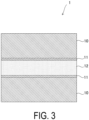
- a laminated film illustrated in FIG. 3 was provided as a stretched film 1.
- This laminated film was prepared by laminating a biaxially stretched PET film 10 having a thickness of 12 ⁇ m on both surfaces of an aluminum foil 12 having a thickness of 7 ⁇ m using a polyurethane adhesive 11.
- a heat seal region (treated portion) 1A was formed in the biaxially stretched PET film 10 by treating the laminated film by the following modification treatment method.
- the thicknesses and degrees of birefringence of a heat seal precursor portion T1, an intermediate portion T2, and an unmodified portion T3 in the heat seal region 1A were measured and calculated by the following methods.
- a carbon dioxide gas laser oscillator (CO 2 laser) that emits a laser beam having a wavelength in an infrared region of 9.3 ⁇ m (attenuation coefficient of 0.035 ⁇ m -1 ) was used as a laser beam light source, and the surface of the biaxially stretched PET film 10 of the stretched film 1 was irradiated with a laser beam under conditions including an output of 100 W, a spot diameter on the irradiation surface of approximately 1 mm, a scanning speed from 11000 to 24000 mm/sec, and a scanning line interval (distance between spot centers) from 0.2 to 0.7 mm, to thereby form a heat seal region 1A having no untreated portion and having a width of 100 mm and a length of 10 mm.
- CO 2 laser carbon dioxide gas laser oscillator
- a sample piece having a thickness of 5 ⁇ m was cut from the heat seal region 1A using a microtome, and a retardation value was measured using a polarizing microscope (Axioplan2 Imaging, available from Carl Zeiss AG) equipped with a tilting compensator.
- the layer to be measured (for example, the heat seal precursor portion T1) was set on a rotation stage at a position where the layer appeared to be the brightest (diagonal position), the scale of the compensator was rotated to cancel the retardation of the layer to be measured and the retardation of the compensator, and the angle value at which the layer appeared to be darkest was read to obtain the retardation value corresponding to the angle value.
- This operation was performed on the heat seal precursor portion T1, the intermediate portion T2, and the unmodified portion T3 in the heat seal region 1A, and the retardation values of the respective portions were obtained.
- the range in which each layer (for example, the heat seal precursor portion T1) appeared dark was measured as the thicknesses of the layer, and the thicknesses of the heat seal precursor portion, the intermediate portion, and the unmodified portion were measured.
- Two samples of the stretched film 1 provided with the heat seal region 1A were prepared, and the heat seal regions 1A were overlapped and heat sealed under conditions including a heat seal bar temperature of 180°C, a heating time of 1 second, and a heat seal pressure of 0.2 MPa to thereby form a sample.
- Five strips each having a width of 15 mm were cut out from the sample, and the seal strengths of the strips were measured at a tensile speed of 300 mm/min by the T-peel method using a Tensilon universal tester (UCT-5T, available from Orientec Corporation). The heat seal strength was calculated as the average of the values of the five strips.
- a stretched film having a heat seal region was prepared in the same manner as in the Example except that the following modification treatment method was employed.
- a carbon dioxide gas laser oscillator (CO 2 laser) with a wavelength of 10.6 ⁇ m was used as a laser beam light source, and the surface of the stretched film was irradiated with a laser beam under conditions including an output of 30 W, a spot diameter on the irradiation surface of approximately 1 mm, a scanning speed from 1528 to 1910 mm/sec, and a scanning line interval (distance between spot centers) of 0.7 mm, to thereby form a heat seal region having a width of 100 mm and a length of 10 mm.
- CO 2 laser carbon dioxide gas laser oscillator
- the “Change rate [%] of unmodified portion” is a change rate in the degree of birefringence of the unmodified portion T3 relative to the degree of birefringence of the non-irradiated portion 1B, and is determined by the following formula: 100 ⁇ (degree of birefringence of non-irradiated portion - degree of birefringence of unmodified portion)/(degree of birefringence of non-irradiated portion).
- the light absorptivity of the laser beam having a wavelength of 9.3 ⁇ m (light attenuation rate: 62%, attenuation coefficient: 0.035 ⁇ m -1 ) used in the Example was higher than the light absorptivity of the laser beam having a wavelength of 10.6 ⁇ m (light attenuation rate: 19%, attenuation coefficient: 0.0076 ⁇ m -1 ) used in the Comparative Example.
- a heat seal precursor portion T1 ("precursor portion" in Table 2) having a thickness of from 1.23 ⁇ m to 10.40 ⁇ m is formed with respect to the biaxially stretched PET film 10 having a thickness of 12 ⁇ m.
- the thickness of the heat seal precursor portion T1 can be adjusted by changing the laser scanning speed in addition to the light absorptivity of the laser beam.
- the thickness of the heat seal precursor portion T1 increases, whereas when the laser scanning speed is high, the thickness of the heat seal precursor portion T1 decreases.
- the thickness of the intermediate portion T2 is generally 2 ⁇ m or less regardless of the thickness of the heat seal precursor portion T1.
- the heat seal strength can be controlled by the thickness of the heat seal precursor portion T1.
- FIG. 4 is a graph showing the results of the Example and Comparative Example with the thickness of the heat seal precursor portion on the horizontal axis and the heat seal strength on the vertical axis.
- the heat seal strength in the Example is lower than that in the Comparative Example, and the results demonstrate that the heat seal strength can be controlled so as to adapt to easy peelability.
- the stretched film 1 is irradiated with a laser beam having high light absorptivity and an attenuation coefficient of 0.02 ⁇ m -1 or greater as described above, to thereby form the heat seal precursor portion T1, the intermediate portion T2, and the unmodified portion T3 in the stretched polyester film in this order from the side irradiated with the laser beam.
- the heat seal strength can be controlled by changing the thickness of the heat seal precursor portion T1, and a desired seal strength can be achieved by suppressing variations in the heat seal strength.
- the thickness of the heat seal precursor portion T1 is preferably adjusted to fall within a range from 1% to 60%, more preferably a range from 1% to 45%, and particularly preferably a range from 1% to 25% of the overall thickness of the stretched polyester film.
- the thickness of the heat seal precursor portion T1 is less than 1% of the overall thickness, appropriate heat sealability cannot be imparted, whereas when the thickness of the heat seal precursor portion T1 is greater than 60% of the overall thickness, easy peelability cannot be realized.
- the heat seal strength can be appropriately adjusted by setting the thickness of the heat seal precursor portion T1 to fall within a range from 1% to 60% of the overall thickness (setting the thickness of the heat seal precursor portion T1 to fall within a range from 0.12 to 7.2 ⁇ m when the overall thickness is 12 ⁇ m).
Landscapes
- Engineering & Computer Science (AREA)
- Mechanical Engineering (AREA)
- Chemical & Material Sciences (AREA)
- Physics & Mathematics (AREA)
- Optics & Photonics (AREA)
- Plasma & Fusion (AREA)
- Health & Medical Sciences (AREA)
- Chemical Kinetics & Catalysis (AREA)
- Medicinal Chemistry (AREA)
- Polymers & Plastics (AREA)
- Organic Chemistry (AREA)
- Manufacturing & Machinery (AREA)
- General Chemical & Material Sciences (AREA)
- Materials Engineering (AREA)
- Thermal Sciences (AREA)
- Crystallography & Structural Chemistry (AREA)
- Toxicology (AREA)
- Treatments Of Macromolecular Shaped Articles (AREA)
- Manufacture Of Macromolecular Shaped Articles (AREA)
- Lining Or Joining Of Plastics Or The Like (AREA)
- Processing And Handling Of Plastics And Other Materials For Molding In General (AREA)
Abstract
Description
- The present invention relates to a stretched film and a method for modification treatment of the stretched film.
- A stretched polyester film exhibits excellent strength, heat resistance, dimensional stability, chemical resistance, and aroma retention, and is useful as a packaging film. However, a stretched polyester film has poor heat sealability, and this poor heat sealability has hindered the use of a stretched polyester film as an inner surface film of a packaging container.
- In response to this problem, a modification treatment method for imparting heat sealability to a stretched polyester film has been proposed. Basically, the modification treatment method employs irradiation of the surface of a stretched film with a laser beam to form a heat seal region with reduced crystallinity. In addition, in order to provide the stretched polyester film with easy peelability, a technique of forming a linear pattern through laser beam irradiation and adjusting the interval between linear patterns to thereby control heat seal strength has been proposed (see
Patent Document 1 below). - Patent Document 1:
JP 2018-58973 A - In the above-mentioned known technique, in order to satisfy a requirement for easy peelability, the heat seal strength is controlled by adjusting the interval between linear patterns through laser beam irradiation. According to this technique, a portion not irradiated with a laser beam; i.e., an untreated portion is present between linear patterns; i.e., treated portions irradiated with a laser beam, and thus the treated portions and the untreated portion are mixedly present in the heat seal region.
- According to such a known technique, when the heat seal regions of a pair of films are brought into face-to-face contact with each other, the linear patterns may be shifted from each other, resulting in a state in which the treated portion and the untreated portion are overlapping. In this state, there is a concern that due to the degree of shifting of the overlapping state, variations are likely to occur in the seal strength that is to be adjusted.
- Thus, an object of the present invention is to solve such problems. That is, an object of the present invention is to form a heat seal region to which heat sealability is imparted in a stretched film, and to achieve a desired seal strength by suppressing variations in seal strength for controlling the seal strength in the heat seal region.
- In order to solve such problems, the present invention has the following configuration.
- A stretched film including a stretched polyester film having a heat seal region on a surface of the film, the heat seal region being irradiated with a laser beam having a wavelength in an infrared region, wherein the heat seal region has a heat seal precursor portion, an intermediate portion, and an unmodified portion formed in this order in a film thickness direction from a surface irradiated with the laser beam, the heat seal precursor portion has a degree of birefringence of 5 × 10⁻³ or less, the intermediate portion has a thickness of 2 µm or less, and a change rate in a degree of birefringence of the unmodified portion is 20% or less relative to a degree of birefringence of a portion not irradiated with the laser beam.
- According to the present invention, when a heat seal region is formed by irradiating a stretched film made of polyester with a laser beam having a wavelength in an infrared region, heat seal strength can be controlled by adjusting the thickness of a heat seal precursor portion among the heat seal precursor portion, intermediate portion, and unmodified portion which are formed in a thickness direction of the film. In addition, variations in heat seal strength can be suppressed, and a desired seal strength can be achieved.
-
-
FIG. 1 is a plan view of a stretched film according to an embodiment of the present invention. -
FIG. 2 is a cross-sectional explanatory view (cross-sectional view taken along line A-A inFIG. 1 ) for illustrating the stretched film according to the embodiment of the present invention. -
FIG. 3 is a cross-sectional explanatory view for illustrating a laminated film of Example. -
FIG. 4 is a graph showing the results of Example and Comparative Example. - Hereinafter, embodiments of the present invention will be described with reference to the drawings. In the following description, the same reference numerals in different drawings denote elements having the same function, and redundant descriptions with regard to each drawing are omitted as appropriate.
- As illustrated in
FIG. 1 , a stretchedfilm 1 includes a biaxially stretched film made of polyester, and has, on a surface of the film, aheat seal region 1A irradiated with a laser beam having a wavelength in an infrared region. In the biaxially stretched polyester film of the illustratedstretched film 1, a region other than theheat seal region 1A is a portion (untreated portion) 1B not irradiated with the laser beam. - As illustrated in a cross-sectional view of
FIG. 2 , in thestretched film 1, theheat seal region 1A has a heat seal precursor portion T1, an intermediate portion T2, and an unmodified portion T3 in a film thickness direction from the surface side irradiated with the laser beam. - Here, the
stretched film 1 is a uniaxially or biaxially stretched polyester film. Specific examples of a polyester resin constituting the polyester film include polyethylene terephthalate, polybutylene terephthalate, polyethylene naphthalate, polybutylene naphthalate, copolymerized polyester, and polycarbonate. - One example of the stretched polyester film is a biaxially stretched polyethylene terephthalate (PET) film. Biaxially stretched polyester films such as a biaxially stretched PET film are known, and methods for their production are also known. Specifically, the biaxially stretched polyester film can be produced, for example, by biaxially stretching an unstretched raw film made of a raw material containing a polyester under conditions where the draw ratios in the machine direction (MD) and transverse direction (TD) are from 2.0 to 6.0 times, and then thermally treating the stretched film at a temperature from 210 to 230°C. As the biaxial stretching method, simultaneous biaxial stretching or sequential biaxial stretching by a tubular process or a tenter process can be employed.
- The
stretched film 1 may be any of a single stretched polyester film, a laminate of a stretched polyester film layer and another resin layer, a laminate of a stretched polyester film layer and a metal (for example, aluminum foil) layer, and a laminate of a stretched polyester film layer, a metal (for example, aluminum foil) layer, and another resin layer. In the case of a laminate, the layer of the stretched polyester film serves as a laser irradiation layer and is laminated with another film so that the heat seal precursor portion T1 is exposed. - The
heat seal region 1A is formed by irradiating the film surface with a laser beam having a wavelength in an infrared region to thereby amorphize thestretched film 1. The crystalline state of the film can be evaluated by the degree of birefringence, and the degree of birefringence of a highly crystalline film is large, whereas the degree of birefringence of an amorphous film is small. - For the control of the heat seal strength, desirably, the entire planar region of the
heat seal region 1A is the treated portion, and as illustrated inFIG. 1 , an untreated portion is absent in theheat seal region 1A in a plan view. However, an untreated portion may be present in theheat seal region 1A as long as the heat seal strength can be controlled. The proportion of the treated portion in theheat seal region 1A is preferably 60% or more, more preferably 70% or more, and particularly preferably 80% or more. For irradiation with a laser beam to form theheat seal region 1A, theheat seal region 1A may be formed by repeatedly scanning the irradiation surface using a laser beam having a predetermined spot diameter on the irradiation surface. In such a case, the proportion of the untreated portion in theheat seal region 1A in a plan view can be reduced by setting the scanning line interval (distance between spot centers) to be smaller than the spot diameter. - The heat seal precursor portion T1 is the outermost surface layer on the laser beam irradiation side in the
heat seal region 1A, and the intermediate portion T2 and the unmodified portion T3 are present below the heat seal precursor portion T1. The degree of birefringence of the heat seal precursor portion T1 is set to 5 × 10⁻³ or less in order to exhibit heat sealability. - The irradiation conditions for irradiation with the laser beam must be specified in order to form the intermediate portion T2 and the unmodified portion T3 below the heat seal precursor portion T1. When the irradiation is implemented with a laser beam having a relatively long wavelength in an infrared region, the overall thickness of the film may become 5 × 10⁻³ or less in terms of the degree of birefringence. However, by irradiating the film with a laser beam having a relatively short wavelength in an infrared region, the thicknesses of the heat seal precursor portion T1 can be controlled in a thickness direction of the entire film, and the intermediate portion T2 and the unmodified portion T3 are formed below the heat seal precursor portion T1.
- It is thought that the thickness of the heat seal precursor portion T1 varies depending on whether the radiated infrared laser beam is easily absorbed by the
stretched film 1. In the case of radiation of a laser beam having a wavelength in an infrared region and easily absorbed by the stretched polyester film, due to this absorption, modification by the laser beam does not easily progress in a thickness direction of thestretched film 1, and the intermediate portion T2 and the unmodified portion T3 are formed below the heat seal precursor T1. - Specifically, when the surface of a stretched polyester film (biaxially stretched PET film) having an overall film thickness of 12 µm is irradiated with a carbon dioxide gas laser having a wavelength of 10.6 µm in an infrared region, a layer having a degree of birefringence of 5 × 10⁻³ or less is formed over the entire layer having a thickness of 12 µm.
- In contrast, when the stretched polyester film (biaxially stretched PET film) is irradiated with a laser beam having a wavelength of 10.2 µm or 9.3 µm and a light attenuation rate that is larger than that of a laser beam having a wavelength of 10.6 µm, in the heat seal precursor portion T1 having a degree of birefringence of 5 × 10⁻³ or less, only a surface of the film having a thickness of 12 µm can be treated, and the intermediate portion T2 and the unmodified portion T3 are formed below the heat seal precursor portion T1.
- The relationship between the wavelength of the laser beam in an infrared region and the light attenuation rate in the biaxially stretched PET film is as shown in Table 1 below.
Table 1 Wavelength [µm] Light Attenuation Rate (12 µm thickness) [%] Attenuation Coefficient [µm-1] 10.6 19 0.0076 10.2 47 0.023 9.3 62 0.035 - Here, the attenuation coefficient represents the ability of the irradiated body (biaxially stretched PET film) to absorb the laser beam regardless of the thickness of the irradiated body. When a laser beam having a light intensity I0 is incident on a medium having a thickness d, and the light intensity after passing through the irradiated body is defined as I, the attenuation coefficient µ can be expressed as follows using Lambert's law.

- The transmittance T is calculated as T = I/I 0, and the absorbance E is -logT = log(I0/I), and therefore the attenuation coefficient µ is calculated as µ = E/d.
- When the laser beam irradiation conditions are set using the attenuation coefficient µ, it is thought that a threshold value exists between the wavelength of 10.6 µm (attenuation coefficient of 0.0076 µm-1) and the wavelength of 10.2 µm (attenuation coefficient of 0.023 µm-1). Thus, for example, by irradiating with a laser beam having an attenuation coefficient of 0.02 µm-1 or greater, the intermediate portion T2 and the unmodified portion T3 can be formed below the heat seal precursor portion T1. However, the laser beam irradiation conditions described here are merely one example, and the heat seal precursor portion T1 having the intermediate portion T2 and the unmodified portion T3 formed therebelow can be produced by irradiating the stretched polyester film with a laser beam having a wavelength in an infrared region and having a relatively high light attenuation rate.
- In the intermediate portion T2, the degree of birefringence is an intermediate value between that of the heat seal precursor portion T1 and that of the unmodified portion T3, and the degree of birefringence of the intermediate portion T2 is greater than 5 × 10⁻³ and smaller than the degree of birefringence of the unmodified portion, and for example, may be continuously changed (gradient structure). In contrast, when formation of the heat seal precursor portion T1 having a degree of birefringence of 5 × 10⁻³ or less is stopped midway in the film thickness direction, the unmodified portion T3 is formed adjacent to the intermediate portion T2 along the irradiation direction of the laser beam. A change rate in the degree of birefringence of the unmodified portion T3 is 20% or less relative to the
portion 1B not irradiated with the laser beam. In this case, the intermediate portion T2 is firmly joined to the heat seal precursor portion T1 and the unmodified portion T3. - For example, when the intermediate portion T2 is absent, peeling may occur at the interface between the heat seal precursor portion T1 and the unmodified portion T3, resulting in problems such as film residue. Meanwhile, when the thickness of the intermediate portion T2 is excessively large, controlling the heat seal strength becomes difficult. Therefore, for example, the thickness of the intermediate portion T2 is preferably from 0.1 µm to 2 µm regardless of the overall thickness of the film.
- Example will be described below.
- A laminated film illustrated in
FIG. 3 was provided as a stretchedfilm 1. This laminated film was prepared by laminating a biaxially stretchedPET film 10 having a thickness of 12 µm on both surfaces of analuminum foil 12 having a thickness of 7 µm using apolyurethane adhesive 11. A heat seal region (treated portion) 1A was formed in the biaxially stretchedPET film 10 by treating the laminated film by the following modification treatment method. The thicknesses and degrees of birefringence of a heat seal precursor portion T1, an intermediate portion T2, and an unmodified portion T3 in theheat seal region 1A were measured and calculated by the following methods. - A carbon dioxide gas laser oscillator (CO2 laser) that emits a laser beam having a wavelength in an infrared region of 9.3 µm (attenuation coefficient of 0.035 µm-1) was used as a laser beam light source, and the surface of the biaxially stretched
PET film 10 of the stretchedfilm 1 was irradiated with a laser beam under conditions including an output of 100 W, a spot diameter on the irradiation surface of approximately 1 mm, a scanning speed from 11000 to 24000 mm/sec, and a scanning line interval (distance between spot centers) from 0.2 to 0.7 mm, to thereby form aheat seal region 1A having no untreated portion and having a width of 100 mm and a length of 10 mm. - For calculation of the degree of birefringence, a sample piece having a thickness of 5 µm was cut from the
heat seal region 1A using a microtome, and a retardation value was measured using a polarizing microscope (Axioplan2 Imaging, available from Carl Zeiss AG) equipped with a tilting compensator. - The layer to be measured (for example, the heat seal precursor portion T1) was set on a rotation stage at a position where the layer appeared to be the brightest (diagonal position), the scale of the compensator was rotated to cancel the retardation of the layer to be measured and the retardation of the compensator, and the angle value at which the layer appeared to be darkest was read to obtain the retardation value corresponding to the angle value. This operation was performed on the heat seal precursor portion T1, the intermediate portion T2, and the unmodified portion T3 in the
heat seal region 1A, and the retardation values of the respective portions were obtained. The degree of birefringence was then calculated on the basis of the obtained retardation value by using the following formula.
- In addition, when the retardation value was measured, the range in which each layer (for example, the heat seal precursor portion T1) appeared dark was measured as the thicknesses of the layer, and the thicknesses of the heat seal precursor portion, the intermediate portion, and the unmodified portion were measured.
- Absorbances A at 943 cm-1 and 1075 cm-1 corresponding to wavelengths of 9.3 µm and 10.6 µm were determined from the infrared spectrum of the biaxially stretched PET film having a thickness of 12 µm measured using a Fourier transform infrared spectrophotometer (FTIR) (FTS7000, available from Varian, Inc.), and the light transmittance %T was calculated from %T = 10-A. The light attenuation rate %E was determined from %E = 100 - %T. The results are shown in Table 1.
- Two samples of the stretched
film 1 provided with theheat seal region 1A were prepared, and theheat seal regions 1A were overlapped and heat sealed under conditions including a heat seal bar temperature of 180°C, a heating time of 1 second, and a heat seal pressure of 0.2 MPa to thereby form a sample. Five strips each having a width of 15 mm were cut out from the sample, and the seal strengths of the strips were measured at a tensile speed of 300 mm/min by the T-peel method using a Tensilon universal tester (UCT-5T, available from Orientec Corporation). The heat seal strength was calculated as the average of the values of the five strips. - A stretched film having a heat seal region was prepared in the same manner as in the Example except that the following modification treatment method was employed.
- A carbon dioxide gas laser oscillator (CO2 laser) with a wavelength of 10.6 µm was used as a laser beam light source, and the surface of the stretched film was irradiated with a laser beam under conditions including an output of 30 W, a spot diameter on the irradiation surface of approximately 1 mm, a scanning speed from 1528 to 1910 mm/sec, and a scanning line interval (distance between spot centers) of 0.7 mm, to thereby form a heat seal region having a width of 100 mm and a length of 10 mm.
- The measurement results of the Example are shown in Table 2, and the measurement results of the Comparative Example are shown in Table 3. In Table 2, the "Change rate [%] of unmodified portion" is a change rate in the degree of birefringence of the unmodified portion T3 relative to the degree of birefringence of the
non-irradiated portion 1B, and is determined by the following formula: 100 × (degree of birefringence of non-irradiated portion - degree of birefringence of unmodified portion)/(degree of birefringence of non-irradiated portion).Table 2 Output [W] 100 Laser spot diameter [mm] 1 Scanning line interval [mm] 0.5 0.5 0.7 0.5 0.5 0.5 0.7 0.5 0.5 Laser scanning speed [mm/sec] 23000 24000 18000 14000 20000 18000 16000 16000 11000 Seal strength [N/15 mm] 3.0 4.0 5.4 6.9 6.9 7.1 7.7 8.4 8.5 Thickness [µm] Precursor portion 1.2 3.2 4.9 7.2 4.2 5.8 5.9 8.0 10.4 Intermediate portion 0.9 0.8 0.9 1.0 0.7 0.6 0.8 0.9 0.8 Degree of birefringence Precursor portion 4.6E-04 2.1E-04 2.1E-04 4.4E-03 2.3E-03 2.8E-03 1.5E-04 1.2E-04 2.1E-04 Intermediate portion 3.6E-02 4.1E-02 4.3E-02 3.3E-02 4.1E-02 3.7E-02 3.4E-02 3.6E-02 1.8E-02 Unmodified portion 1.7E-01 1.2E-01 1.4E-01 8.2E-02 1.3E-01 9.9E-02 1.1E-01 9.4E-02 8.9E-02 Non-irradiated portion 1.6E-01 1.3E-01 1.3E-01 7.8E-02 1.4E-01 1.2E-01 1.2E-01 1.1E-01 9.7E-02 Change rate [%] of unmodified portion. 5.8 10.9 0.6 6.3 5.9 15.7 4.4 17.0 8.5 Table 3 Output [W] 30 Laser spot diameter [mm] 1 Scanning line interval [mm] 0.7 Laser scanning speed 1528 1910 Seal strength [N/15 mm] 10.2 0.3 Precursor portion thickness [µm] 12.0 0.0 Degree of birefringence of laser irradiated portion 1.1E-03 1.3E-01 - The light absorptivity of the laser beam having a wavelength of 9.3 µm (light attenuation rate: 62%, attenuation coefficient: 0.035 µm-1) used in the Example was higher than the light absorptivity of the laser beam having a wavelength of 10.6 µm (light attenuation rate: 19%, attenuation coefficient: 0.0076 µm-1) used in the Comparative Example. As a result, in the Example, a heat seal precursor portion T1 ("precursor portion" in Table 2) having a thickness of from 1.23 µm to 10.40 µm is formed with respect to the biaxially stretched
PET film 10 having a thickness of 12 µm. It is thought that this result is attributed to the fact that when a laser beam having high light absorptivity is used, absorption occurs strongly on the laser beam irradiation surface side, and thus absorption in the depth direction of the biaxially stretchedPET film 10 becomes weaker than that on the surface side. In contrast, in the Comparative Example, the entire thickness is modified, and the heat seal precursor portion T1, the intermediate portion T2, and the unmodified portion T3 are not formed unlike the case of the Example. - The results of the Example suggest that the thickness of the heat seal precursor portion T1 can be adjusted by changing the laser scanning speed in addition to the light absorptivity of the laser beam. In general, when the laser scanning speed is low, the thickness of the heat seal precursor portion T1 increases, whereas when the laser scanning speed is high, the thickness of the heat seal precursor portion T1 decreases. Meanwhile, the thickness of the intermediate portion T2 is generally 2 µm or less regardless of the thickness of the heat seal precursor portion T1.
- As is clear from the results of the Example, the heat seal strength can be controlled by the thickness of the heat seal precursor portion T1.
FIG. 4 is a graph showing the results of the Example and Comparative Example with the thickness of the heat seal precursor portion on the horizontal axis and the heat seal strength on the vertical axis. In the Example, it can be said that the heat seal strength generally increases in accordance with the thickness of the heat seal precursor portion T1. In addition, the heat seal strength in the Example is lower than that in the Comparative Example, and the results demonstrate that the heat seal strength can be controlled so as to adapt to easy peelability. - As described above, when the
heat seal region 1A is to be formed by using the stretchedfilm 1 or the modification treatment method of the stretchedfilm 1 according to the embodiment of the present invention, the stretchedfilm 1 is irradiated with a laser beam having high light absorptivity and an attenuation coefficient of 0.02 µm-1 or greater as described above, to thereby form the heat seal precursor portion T1, the intermediate portion T2, and the unmodified portion T3 in the stretched polyester film in this order from the side irradiated with the laser beam. - As a result, even when the
heat seal region 1A is treated uniformly in a planar manner, the heat seal strength can be controlled by changing the thickness of the heat seal precursor portion T1, and a desired seal strength can be achieved by suppressing variations in the heat seal strength. - In particular, in order to adapt to easy peelability, the thickness of the heat seal precursor portion T1 is preferably adjusted to fall within a range from 1% to 60%, more preferably a range from 1% to 45%, and particularly preferably a range from 1% to 25% of the overall thickness of the stretched polyester film. When the thickness of the heat seal precursor portion T1 is less than 1% of the overall thickness, appropriate heat sealability cannot be imparted, whereas when the thickness of the heat seal precursor portion T1 is greater than 60% of the overall thickness, easy peelability cannot be realized. The graph of
FIG. 4 also shows that the heat seal strength can be appropriately adjusted by setting the thickness of the heat seal precursor portion T1 to fall within a range from 1% to 60% of the overall thickness (setting the thickness of the heat seal precursor portion T1 to fall within a range from 0.12 to 7.2 µm when the overall thickness is 12 µm). - 1: Stretched film, 1A: Heat seal region, 1B: Non-irradiated portion (untreated portion), T1: Heat seal precursor portion, T2: Intermediate portion, T3: Unmodified portion, 10: Biaxially stretched PET film, 11: Polyurethane adhesive, 12: Aluminum foil
Claims (5)
- A stretched film comprising a stretched polyester film having a heat seal region on a surface of the film, the heat seal region being irradiated with a laser beam having a wavelength in an infrared region, whereinthe heat seal region has a heat seal precursor portion, an intermediate portion, and an unmodified portion formed in this order in a film thickness direction from the surface irradiated with the laser beam,the heat seal precursor portion has a degree of birefringence of 5 × 10⁻³ or less,the intermediate portion has a thickness of 2 µm or less, anda change rate in a degree of birefringence of the unmodified portion is 20% or less relative to a degree of birefringence of a portion not irradiated with the laser beam.
- The stretched film according to claim 1, wherein a thickness of the heat seal precursor portion is from 1% to 60% of an overall thickness of the film.
- The stretched film according to claim 1, wherein the stretched polyester film is a stretched polyethylene terephthalate film.
- The stretched film according to claim 1, wherein the stretched film is laminated with another film such that the heat seal precursor portion is exposed.
- A method for treating a stretched film, the method comprising irradiating an entire surface or a portion of the surface of a stretched film with a laser beam having a wavelength in an infrared region to form a heat seal region, wherein
the laser beam is a laser beam having an attenuation coefficient of 0.02 µm-1 or greater.
Applications Claiming Priority (2)
| Application Number | Priority Date | Filing Date | Title |
|---|---|---|---|
| JP2021215079A JP7287450B1 (en) | 2021-12-28 | 2021-12-28 | Stretched film made of polyester and its modification treatment method |
| PCT/JP2022/042093 WO2023127325A1 (en) | 2021-12-28 | 2022-11-11 | Stretched film and method for modification treatment of stretched film |
Publications (2)
| Publication Number | Publication Date |
|---|---|
| EP4431555A1 true EP4431555A1 (en) | 2024-09-18 |
| EP4431555A4 EP4431555A4 (en) | 2025-12-17 |
Family
ID=86611024
Family Applications (1)
| Application Number | Title | Priority Date | Filing Date |
|---|---|---|---|
| EP22915557.7A Pending EP4431555A4 (en) | 2021-12-28 | 2022-11-11 | STRETCHED FILM AND STRETCHED FILM MODIFICATION PROCESS |
Country Status (6)
| Country | Link |
|---|---|
| US (1) | US20240300217A1 (en) |
| EP (1) | EP4431555A4 (en) |
| JP (1) | JP7287450B1 (en) |
| KR (1) | KR20240091205A (en) |
| CN (1) | CN118355061A (en) |
| WO (1) | WO2023127325A1 (en) |
Family Cites Families (8)
| Publication number | Priority date | Publication date | Assignee | Title |
|---|---|---|---|---|
| JP2005319501A (en) * | 2004-05-11 | 2005-11-17 | Keyence Corp | Laser marking method for thin film, apparatus therefor, and film material |
| EP3130629B1 (en) * | 2014-06-12 | 2019-01-23 | Toppan Printing Co., Ltd. | Method for imparting heat sealability to biaxially oriented polyester film, and method for producing packaging container |
| CN107709422B (en) * | 2015-07-07 | 2021-03-09 | 凸版印刷株式会社 | Film, packaging bag using the same, and method for imparting heat-sealability to film |
| JP6079844B1 (en) * | 2015-09-07 | 2017-02-15 | 凸版印刷株式会社 | Laser processing method to film |
| EP3348382A4 (en) * | 2015-09-07 | 2018-10-03 | Toppan Printing Co., Ltd. | Laser processing apparatus |
| JP6897049B2 (en) | 2016-10-04 | 2021-06-30 | 凸版印刷株式会社 | Film and film manufacturing method |
| JP7027700B2 (en) * | 2017-05-11 | 2022-03-02 | 凸版印刷株式会社 | Film processing method |
| JP7205116B2 (en) * | 2018-09-04 | 2023-01-17 | 東洋製罐グループホールディングス株式会社 | Method for producing heat-sealable film |
-
2021
- 2021-12-28 JP JP2021215079A patent/JP7287450B1/en active Active
-
2022
- 2022-11-11 CN CN202280080073.9A patent/CN118355061A/en active Pending
- 2022-11-11 EP EP22915557.7A patent/EP4431555A4/en active Pending
- 2022-11-11 WO PCT/JP2022/042093 patent/WO2023127325A1/en not_active Ceased
- 2022-11-11 KR KR1020247018029A patent/KR20240091205A/en active Pending
-
2024
- 2024-05-21 US US18/670,246 patent/US20240300217A1/en active Pending
Also Published As
| Publication number | Publication date |
|---|---|
| CN118355061A (en) | 2024-07-16 |
| WO2023127325A1 (en) | 2023-07-06 |
| KR20240091205A (en) | 2024-06-21 |
| EP4431555A4 (en) | 2025-12-17 |
| US20240300217A1 (en) | 2024-09-12 |
| JP7287450B1 (en) | 2023-06-06 |
| JP2023098364A (en) | 2023-07-10 |
Similar Documents
| Publication | Publication Date | Title |
|---|---|---|
| US10035339B2 (en) | Laser cut articles | |
| EP2466368B1 (en) | Polarizing diffuser film, method for producing polarizing diffuser film, and liquid crystal display device comprising polarizing diffuser film | |
| EP2426530B1 (en) | Method of producing roll of laminate strip with polarizing film | |
| EP1495071B1 (en) | Enhanced k-type polarizer | |
| EP2055423A1 (en) | Optical film cutting method and optical film | |
| EP2724856B1 (en) | Laminate film and automotive window glass using same | |
| EP3130629B1 (en) | Method for imparting heat sealability to biaxially oriented polyester film, and method for producing packaging container | |
| KR20050051642A (en) | Enhanced heat mirror films | |
| JP2004503402A (en) | Wrinkle-resistant infrared reflective film and non-planar laminated article produced therefrom | |
| EP0500943A1 (en) | Method of making cylindrical member for paper container | |
| US10286489B2 (en) | Apparatus and method for laser cutting using a support member having a gold facing layer | |
| KR20170039075A (en) | Multilayer film | |
| EP4431555A1 (en) | Stretched film and method for modification treatment of stretched film | |
| JP2025156538A (en) | Polarizing plate and manufacturing method thereof | |
| KR20220133108A (en) | Method for producing stretched film | |
| DE69827600T2 (en) | POLYESTER FILM | |
| CN115398287B (en) | Polarizing plate and method for manufacturing the same, and image display device using the same | |
| WO2020110644A1 (en) | Method for production of cut film | |
| JP2008279696A (en) | Multilayered laminate structure, manufacturing method and manufacturing device | |
| WO2020090502A1 (en) | Method of manufacturing cut film | |
| KR20250156608A (en) | Information card and method for manufacturing thereof | |
| TW202608697A (en) | Information Card and its Manufacturing Method | |
| CN118226559A (en) | Optical laminate, optical laminate roll, and method for producing polarizing plate |
Legal Events
| Date | Code | Title | Description |
|---|---|---|---|
| STAA | Information on the status of an ep patent application or granted ep patent |
Free format text: STATUS: THE INTERNATIONAL PUBLICATION HAS BEEN MADE |
|
| PUAI | Public reference made under article 153(3) epc to a published international application that has entered the european phase |
Free format text: ORIGINAL CODE: 0009012 |
|
| STAA | Information on the status of an ep patent application or granted ep patent |
Free format text: STATUS: REQUEST FOR EXAMINATION WAS MADE |
|
| 17P | Request for examination filed |
Effective date: 20240612 |
|
| AK | Designated contracting states |
Kind code of ref document: A1 Designated state(s): AL AT BE BG CH CY CZ DE DK EE ES FI FR GB GR HR HU IE IS IT LI LT LU LV MC ME MK MT NL NO PL PT RO RS SE SI SK SM TR |
|
| DAV | Request for validation of the european patent (deleted) | ||
| DAX | Request for extension of the european patent (deleted) | ||
| A4 | Supplementary search report drawn up and despatched |
Effective date: 20251119 |
|
| RIC1 | Information provided on ipc code assigned before grant |
Ipc: C08J 7/00 20060101AFI20251113BHEP Ipc: B23K 26/352 20140101ALI20251113BHEP Ipc: B29C 65/16 20060101ALI20251113BHEP Ipc: C08J 5/18 20060101ALI20251113BHEP |