EP4431469A2 - Cullet and cullet water handling system - Google Patents
Cullet and cullet water handling system Download PDFInfo
- Publication number
- EP4431469A2 EP4431469A2 EP24184019.8A EP24184019A EP4431469A2 EP 4431469 A2 EP4431469 A2 EP 4431469A2 EP 24184019 A EP24184019 A EP 24184019A EP 4431469 A2 EP4431469 A2 EP 4431469A2
- Authority
- EP
- European Patent Office
- Prior art keywords
- glass
- platform
- waste
- molten glass
- sluice
- Prior art date
- Legal status (The legal status is an assumption and is not a legal conclusion. Google has not performed a legal analysis and makes no representation as to the accuracy of the status listed.)
- Granted
Links
Images




Classifications
-
- C—CHEMISTRY; METALLURGY
- C03—GLASS; MINERAL OR SLAG WOOL
- C03B—MANUFACTURE, SHAPING, OR SUPPLEMENTARY PROCESSES
- C03B7/00—Distributors for the molten glass; Means for taking-off charges of molten glass; Producing the gob, e.g. controlling the gob shape, weight or delivery tact
-
- C—CHEMISTRY; METALLURGY
- C03—GLASS; MINERAL OR SLAG WOOL
- C03B—MANUFACTURE, SHAPING, OR SUPPLEMENTARY PROCESSES
- C03B9/00—Blowing glass; Production of hollow glass articles
- C03B9/30—Details of blowing glass; Use of materials for the moulds
- C03B9/44—Means for discharging combined with glass-blowing machines, e.g. take-outs
-
- B—PERFORMING OPERATIONS; TRANSPORTING
- B65—CONVEYING; PACKING; STORING; HANDLING THIN OR FILAMENTARY MATERIAL
- B65G—TRANSPORT OR STORAGE DEVICES, e.g. CONVEYORS FOR LOADING OR TIPPING, SHOP CONVEYOR SYSTEMS OR PNEUMATIC TUBE CONVEYORS
- B65G11/00—Chutes
- B65G11/02—Chutes of straight form
- B65G11/026—Chutes of straight form for bulk
-
- B—PERFORMING OPERATIONS; TRANSPORTING
- B65—CONVEYING; PACKING; STORING; HANDLING THIN OR FILAMENTARY MATERIAL
- B65G—TRANSPORT OR STORAGE DEVICES, e.g. CONVEYORS FOR LOADING OR TIPPING, SHOP CONVEYOR SYSTEMS OR PNEUMATIC TUBE CONVEYORS
- B65G19/00—Conveyors comprising an impeller or a series of impellers carried by an endless traction element and arranged to move articles or materials over a supporting surface or underlying material, e.g. endless scraper conveyors
- B65G19/04—Conveyors comprising an impeller or a series of impellers carried by an endless traction element and arranged to move articles or materials over a supporting surface or underlying material, e.g. endless scraper conveyors for moving bulk material in open troughs or channels
- B65G19/06—Conveyors comprising an impeller or a series of impellers carried by an endless traction element and arranged to move articles or materials over a supporting surface or underlying material, e.g. endless scraper conveyors for moving bulk material in open troughs or channels the impellers being scrapers similar in size and shape to the cross-section of the trough or channel
- B65G19/08—Conveyors comprising an impeller or a series of impellers carried by an endless traction element and arranged to move articles or materials over a supporting surface or underlying material, e.g. endless scraper conveyors for moving bulk material in open troughs or channels the impellers being scrapers similar in size and shape to the cross-section of the trough or channel and attached to a single belt, rope or chain
-
- B—PERFORMING OPERATIONS; TRANSPORTING
- B65—CONVEYING; PACKING; STORING; HANDLING THIN OR FILAMENTARY MATERIAL
- B65G—TRANSPORT OR STORAGE DEVICES, e.g. CONVEYORS FOR LOADING OR TIPPING, SHOP CONVEYOR SYSTEMS OR PNEUMATIC TUBE CONVEYORS
- B65G51/00—Conveying articles through pipes or tubes by fluid flow or pressure; Conveying articles over a flat surface, e.g. the base of a trough, by jets located in the surface
- B65G51/02—Directly conveying the articles, e.g. slips, sheets, stockings, containers or workpieces, by flowing gases
- B65G51/03—Directly conveying the articles, e.g. slips, sheets, stockings, containers or workpieces, by flowing gases over a flat surface or in troughs
-
- C—CHEMISTRY; METALLURGY
- C03—GLASS; MINERAL OR SLAG WOOL
- C03B—MANUFACTURE, SHAPING, OR SUPPLEMENTARY PROCESSES
- C03B11/00—Pressing molten glass or performed glass reheated to equivalent low viscosity without blowing
-
- C—CHEMISTRY; METALLURGY
- C03—GLASS; MINERAL OR SLAG WOOL
- C03B—MANUFACTURE, SHAPING, OR SUPPLEMENTARY PROCESSES
- C03B25/00—Annealing glass products
- C03B25/04—Annealing glass products in a continuous way
-
- C—CHEMISTRY; METALLURGY
- C03—GLASS; MINERAL OR SLAG WOOL
- C03B—MANUFACTURE, SHAPING, OR SUPPLEMENTARY PROCESSES
- C03B35/00—Transporting of glass products during their manufacture, e.g. hot glass lenses, prisms
-
- C—CHEMISTRY; METALLURGY
- C03—GLASS; MINERAL OR SLAG WOOL
- C03B—MANUFACTURE, SHAPING, OR SUPPLEMENTARY PROCESSES
- C03B35/00—Transporting of glass products during their manufacture, e.g. hot glass lenses, prisms
- C03B35/005—Transporting hot solid glass products other than sheets or rods, e.g. lenses, prisms, by suction or floatation
-
- C—CHEMISTRY; METALLURGY
- C03—GLASS; MINERAL OR SLAG WOOL
- C03B—MANUFACTURE, SHAPING, OR SUPPLEMENTARY PROCESSES
- C03B7/00—Distributors for the molten glass; Means for taking-off charges of molten glass; Producing the gob, e.g. controlling the gob shape, weight or delivery tact
- C03B7/10—Cutting-off or severing the glass flow with the aid of knives or scissors or non-contacting cutting means, e.g. a gas jet; Construction of the blades used
-
- C—CHEMISTRY; METALLURGY
- C03—GLASS; MINERAL OR SLAG WOOL
- C03B—MANUFACTURE, SHAPING, OR SUPPLEMENTARY PROCESSES
- C03B7/00—Distributors for the molten glass; Means for taking-off charges of molten glass; Producing the gob, e.g. controlling the gob shape, weight or delivery tact
- C03B7/14—Transferring molten glass or gobs to glass blowing or pressing machines
-
- C—CHEMISTRY; METALLURGY
- C03—GLASS; MINERAL OR SLAG WOOL
- C03B—MANUFACTURE, SHAPING, OR SUPPLEMENTARY PROCESSES
- C03B9/00—Blowing glass; Production of hollow glass articles
-
- B—PERFORMING OPERATIONS; TRANSPORTING
- B65—CONVEYING; PACKING; STORING; HANDLING THIN OR FILAMENTARY MATERIAL
- B65G—TRANSPORT OR STORAGE DEVICES, e.g. CONVEYORS FOR LOADING OR TIPPING, SHOP CONVEYOR SYSTEMS OR PNEUMATIC TUBE CONVEYORS
- B65G2201/00—Indexing codes relating to handling devices, e.g. conveyors, characterised by the type of product or load being conveyed or handled
- B65G2201/04—Bulk
- B65G2201/047—Articles manipulated as bulk
-
- B—PERFORMING OPERATIONS; TRANSPORTING
- B65—CONVEYING; PACKING; STORING; HANDLING THIN OR FILAMENTARY MATERIAL
- B65G—TRANSPORT OR STORAGE DEVICES, e.g. CONVEYORS FOR LOADING OR TIPPING, SHOP CONVEYOR SYSTEMS OR PNEUMATIC TUBE CONVEYORS
- B65G2207/00—Indexing codes relating to constructional details, configuration and additional features of a handling device, e.g. Conveyors
- B65G2207/22—Heat or fire protection
-
- B—PERFORMING OPERATIONS; TRANSPORTING
- B65—CONVEYING; PACKING; STORING; HANDLING THIN OR FILAMENTARY MATERIAL
- B65G—TRANSPORT OR STORAGE DEVICES, e.g. CONVEYORS FOR LOADING OR TIPPING, SHOP CONVEYOR SYSTEMS OR PNEUMATIC TUBE CONVEYORS
- B65G2812/00—Indexing codes relating to the kind or type of conveyors
- B65G2812/03—Vibrating conveyors
- B65G2812/0384—Troughs, tubes or the like
- B65G2812/0396—Troughs, tubes or the like characterised by the material
-
- Y—GENERAL TAGGING OF NEW TECHNOLOGICAL DEVELOPMENTS; GENERAL TAGGING OF CROSS-SECTIONAL TECHNOLOGIES SPANNING OVER SEVERAL SECTIONS OF THE IPC; TECHNICAL SUBJECTS COVERED BY FORMER USPC CROSS-REFERENCE ART COLLECTIONS [XRACs] AND DIGESTS
- Y02—TECHNOLOGIES OR APPLICATIONS FOR MITIGATION OR ADAPTATION AGAINST CLIMATE CHANGE
- Y02P—CLIMATE CHANGE MITIGATION TECHNOLOGIES IN THE PRODUCTION OR PROCESSING OF GOODS
- Y02P40/00—Technologies relating to the processing of minerals
- Y02P40/50—Glass production, e.g. reusing waste heat during processing or shaping
Definitions
- This patent application discloses systems and methods for glassware manufacturing and, more particularly, a system for handling glassware manufacturing waste.
- Glass container manufacturing processes can include using a glassware forming machine to shape and form glass containers from molten glass.
- a stream of the molten glass can be separated into a glass gob, formed into a parison, and shaped into a container. Additionally, the glass gobs, parisons, containers, or pieces thereof may be rejected due to various reasons. These rejected materials, along with streams of molten waste glass, are known as internal cullet and can be recycled to a glass melter to produce molten glass.
- the present disclosure embodies a number of aspects that can be implemented separately from or in combination with each other.
- a glassware manufacturing system in accordance with one aspect of the disclosure, comprises an architectural installation having a forming floor and no basement beneath the forming floor; a glassware forming machine carried on the forming floor; a molten glass feeder configured to provide molten glass to the glassware forming machine; and a glassware manufacturing waste handling system, including: a sump pit in the forming floor; a waste liquid trench substantially surrounding the glassware forming machine and flowing to the sump pit; and at least one of a cullet material handler or a molten waste glass sluice, configured to receive molten glass from the molten glass feeder and hot glassware rejects from the glassware forming machine.
- the glassware manufacturing system may include an enclosure over the cullet trench, steam removal ductwork, an annealing lehr, a cold cullet return conveyor, a reject conveyor, a cullet crusher, a molten glass chute, and/or an operator pitch chute.
- a glassware manufacturing waste handling system in accordance with one aspect of the disclosure, comprises a sump pit in a forming floor of an architectural installation, where the architectural installation has no basement beneath the forming floor; a waste liquid trench substantially surrounding a glassware forming machine carried on the forming floor, the waste liquid trench flowing to the sump pit; and at least one of a cullet material handler or a molten waste glass sluice, configured to receive molten glass from a molten glass feeder and hot glassware rejects from the glassware forming machine.
- a method for handling glassware manufacturing waste comprises providing process water to a glassware forming machine carried by a forming floor, where the process water drains from the glassware forming machine to the forming floor; collecting the process water from the forming floor using a waste liquid trench and a sump pit formed in the forming floor; collecting cullet from the glassware forming machine using at least one of a cullet material handler or a molten waste glass sluice disposed adjacent to the glassware forming machine; and recycling the process water from the sump pit to the glassware forming machine.
- the method may include treating the process water from the sump pit.
- a molten waste glass handling sluice in accordance with another aspect of the disclosure, extends along a longitudinal axis, and includes a base; a platform carried above the base and including an upper wall having a plurality of apertures to deliver fluid from a location below the upper wall to a location above the upper wall; side walls extending in a direction upwardly away from the upper wall; an upstream inlet to receive hot molten glass; and a downstream outlet to transmit cooled glass.
- a method of handling waste molten glass comprises receiving waste molten glass on a cushion of gas on a platform, and conveying the waste molten glass in a downstream direction on the cushion of gas on the platform.
- This method also may include vibrating the platform to assist with conveying the waste molten glass in the downstream direction, adjusting one or more characteristics of the vibrating to affect a flow of the waste molten glass along the platform, and/or adjusting one or more characteristics of the gas to affect a flow of the waste molten glass along the platform.
- a glassware manufacturing system contains and recycles process water within the system, limits internal cullet handling to a forming floor, and minimizes the volume and improves the quality of process water, thereby reducing environmental disposal costs and improving safety in a glassware forming area.
- External cullet arises from post-consumer recycling of glass products.
- Internal cullet arises from waste glass in a glass factory, including waste gobs or charges of molten glass from a gob or charge feeder spout, or streams of molten glass from a glass melter, a finer, a forehearth, or the gob or charge feeder spout, or hot glassware rejects, or cold glassware rejects.
- the forming systems can include a system that allows process water and/or other material to gravity flow through collection pans, pipes, and chutes onto the basement floor and into an API oil-water separator pit. Oils and grease can be skimmed from the collected process water, and the remaining process water can be recycled back into the system. As part of this process, some process water may escape the basement with the cullet and has the potential to be comingled with storm or other water. This requires collection and conveyance of the escaped water back to the basement, where increased water volumes, due to comingling with storm water, can upset the system water balance and result in excess water that must be hauled off for environmental disposal at extra expense.
- the present disclosure is directed to a glassware manufacturing system, and a glassware manufacturing waste handling system that includes an automated and closed cullet and cullet water handling system.
- the glassware manufacturing system can be contained within a production building without a basement. Additionally, the cullet, process, and/or shear water can be collected and recycled within the system to minimize cost from environmental disposal, and cullet handling can be limited to the forming floor.
- the glassware manufacturing system 10 can comprise an architectural installation 14, a glassware forming machine 16 carried on a forming floor 18 of the installation 14, a glass furnace forehearth 20, and a glassware manufacturing waste handling system 12.
- the system 10 also may include a submerged combustion melting (SCM) furnace or "melter” and a molten glass finer between the melter and the forehearth 20.
- SCM submerged combustion melting
- the architectural installation 14 can include a concrete foundation establishing the forming floor 18.
- the architectural installation 14 may also include a factory building (not shown) on the foundation including walls, a roof, and/or an upper level or raised platform above the forming floor 18.
- the architectural installation 14 can be configured to support and shelter a compact, single-level glassware manufacturing system 10.
- the architectural installation 14 can be configured to carry glassware forming equipment.
- the architectural installation 14 has no basement beneath the forming floor 18 as utilized in conventional systems.
- a basement is required because traditional cullet chutes use large amounts of high pressure water to keep the steel chutes cool and maintain the flow of rejected or streaming glass into a basement, where the water and cullet are collected.
- the level of the water and cullet collecting equipment has been at least one full level below a forming machine.
- utilizing a basement may be less efficient compared to implementing the glassware manufacturing system 10 disclosed herein because using the glassware manufacturing system 10 can reduce the amount of capital investment needed, allow for reductions in process equipment labor requirements, and increase up-time across the glassware forming process.
- the term "basement” includes the lowest habitable level of the glass factory below a forming floor of the factory and can include a first level or a below grade or below ground level portion that may require excavation of earthen material. In contrast, according to the present disclosure, no basement is required, such that the architectural installation 14 includes a concrete slab with earthen material directly underneath the slab, wherein the slab establishes the forming floor 18.
- the forming floor 18 can be sloped to direct process water and/or other liquids on the forming floor 18 away from process equipment.
- process water may include shear spray water, cooling water, cullet water, quench water, and the like.
- the forming floor 18 can be sloped away from a glassware forming machine 16 to a waste liquid trench 22.
- the forming floor 18 can be sloped or crowned such that liquid efficiently flows but does not create a safety hazard within the glassware manufacturing system 10. It is contemplated that the forming floor 18 may be sloped or crowned just enough to facilitate runoff of liquids, like water, lubricants, or the like.
- the glassware manufacturing system 10 can include the glassware forming machine 16 carried on the forming floor 18.
- the glassware forming machine 16 can include a machine that holds and moves molten glass, often in the form of a glass gob, and shapes the molten glass to form glassware (e.g., containers).
- the glassware forming machine 16 may include an individual section (IS) machine comprising a bank of identical sections, each of which contains a complete set of equipment to form a glass container. The sections may be in a row and may be fed molten glass from a forehearth and moving chutes.
- the glassware forming machine 16 can be completely housed by the architectural installation 14. It will be appreciated that other types of forming machines may be used in the glassware manufacturing system 10.
- the glassware manufacturing system 10 can include a glass furnace forehearth 20 having a molten glass feeder 24 configured to provide molten glass 26 to the glassware forming machine 16.
- the glass furnace forehearth 20 can be located downstream of a melting furnace (not shown) and may be part of a hot-end subsystem.
- the glass furnace forehearth 20 can receive molten glass from the furnace and cool the molten glass to a uniform temperature and viscosity suitable for downstream forming operations.
- the molten glass feeder 24 can be located at a downstream end of the glass furnace forehearth 20 and is configured to produce molten glass portions.
- the molten glass feeder 24 can receive the molten glass from the glass furnace forehearth 20, produce a continuous stream of molten glass, and separate the stream into discrete glass gobs that freefall into gob handling equipment (not shown), which may include a series of distributors, scoops, chutes, deflectors, and funnels.
- the gob handling equipment may also include ancillary lubrication equipment to apply lubricants to the gob handling equipment and liquid separators to separate or otherwise process the lubricants.
- the molten glass feeder 24 and gob handling equipment can be configured to provide glass gobs to the glassware forming machine 16.
- the molten glass feeder 24 can receive the molten glass from the glass furnace forehearth 20, produce a continuous stream of molten glass that that is fed downwardly into a molten glass transport cup and thereafter severed to produce a discrete portion of molten glass carried in the cup and separated from the molten glass stream.
- the glass-filled cup is thereafter moved to the glassware forming machine 16, over a mold, and either inverted to dump the glass in the mold, split open to dump the glass in the mold, or opened at an openable bottom end to dump the glass in the mold.
- the molten glass feeder 24 can receive the molten glass from the glass furnace forehearth 20, produce a continuous stream of molten glass that is directly injected into an inverted mold, and then severed to produce a discrete portion of molten glass carried in the cup and separated from the molten glass stream.
- no gob handling equipment and no molten glass cup are used; instead, the molten glass is delivered directly into the mold.
- molten glass portion includes a molten glass gob, gather, stream, chunk, charge, mold charge, and the like.
- a molten glass portion may include a molten glass gob cut from a stream of molten glass produced by a gob feeder and then dropped into gob handling equipment, a transport cup, or a mold.
- a molten glass portion may include a stream of molten glass delivered from an upstream continuous supply of molten glass, and thereafter separated from the upstream continuous supply of molten glass in any suitable manner.
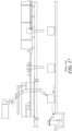
- the glassware manufacturing system 10 can include the glassware manufacturing waste handling system 12, which can further include a shear spray collection system 13 ( FIG. 1 ), a sump pit 28 ( FIG. 2 ), the waste liquid trench 22, and a cullet material handler 30.
- the glassware manufacturing waste handling system 12 can be used to remove, handle, and/or recycle process liquid, for example, water, oil, and other materials, used during forming processes, and for removing cullet and glassware rejects.
- the glassware manufacturing waste handling system 12 can include the sump pit 28 in the forming floor 18.
- the sump pit 28 can include a pit or lowest-most volume in the forming floor 18 for collecting the process water and other liquid resulting from the forming process.
- the sump pit 28 can be located at a low portion of the forming floor 18 so that the liquid can generally flow from the glassware forming machine 16 and equipment to the sump pit 28.
- the sump pit 28 may include means, for example a pump (not shown), for further transferring the liquid for treatment and/or other handling.
- the liquid waste in the sump pit 28 can be transferred for treatment, for example, using a pump, and then can be recycled.
- the sump pit 28 may include an oil-water separator (e.g., an API oil-water separator) and/or other treatment means.
- the glassware manufacturing system 10 can include a closed or open recirculating loop for treating and/or recycling the process water and other liquid, which can contribute to reducing human intervention in the forming process and potential negative environmental impact while improving safety and process stability.
- the glassware manufacturing waste handling system 12 can include a waste liquid trench 22 substantially surrounding the glassware forming machine 16 and flowing to the sump pit 28.
- substantially surround means extending between 240 and 360 angular degrees around including all ranges, sub-ranges, and values including endpoints of that range.
- the waste liquid trench 22 can be carried by and integrally formed in the forming floor 18. When the forming floor 18 is sloped, the liquid can fall onto the forming floor 18 from the glassware forming machine 16, flow down the sloped forming floor 18 to the waste liquid trench 22, and flow through the waste liquid trench 22 to the sump pit 28. In FIG. 1 , the waste liquid trench 22 forms a rectangle and completely surrounds the glassware forming machine 16.
- waste liquid trench 22 may include other configurations and may include more than one trench that flows to the sump pit 28.
- the waste liquid trench 22 may also substantially surround and/or be located adjacent to other equipment within the glassware manufacturing system 10, for example steam removal ductwork 32.
- the glassware manufacturing waste handling system 12 can include the cullet material handler 30 configured to receive discrete molten glass portions and unused molten glass streams from the molten glass feeder 24.
- the handler 30 also may be configured to receive molten glass streams from the SCM furnace and/or the finer when it is desired to drain or "dump" molten glass therefrom, for example, to accommodate a glass color changeover, equipment maintenance, equipment relocation, or the like. Any suitable conduit, sluice, or the like may be used to communicate drains, outlets, or the like of the SCM furnace and/or the finer to the handler 30.
- the handler 30 is also configured to receive hot glassware rejects from the glassware forming machine 16, cold glassware rejects from a cold cullet return conveyor 48, and the like.
- the cullet material handler 30 may include a cullet drag chain, which may include a chain conveyor comprising a continuous chain arrangement with a series of single pendants, where the chain arrangement can be driven by a motor to convey the rejected molten glass portions, the unused molten glass streams, the cold glassware rejects, and/or the hot glassware rejects.
- the cullet drag chain can include a stainless steel hinged drag chain that is suitable for exposure to heat and a humid environment.
- the cullet material handler 30 can include other types of conveyors configured to handle hot glass and glass cullet, for example a belt conveyor, a pneumatic conveyor, and/or any other type of material handler suitable for use in moving cullet.
- the molten glass feeder 24 distributes glass gobs to the glassware forming machine 16
- some of the glass gobs may be rejected due to commercial variations.
- At least some of the rejected glass gobs may be transferred from the molten glass feeder 24 and/or the glassware forming machine 16 to the cullet material handler 30 by way of a waste molten glass chute 34.
- the waste molten glass chute 34 may include a chute or sloping channel or enclosure through which rejected mold charges can fall and be directed to the cullet material handler 30.
- the waste molten glass chute 34 may include material suitable for handling high temperatures and/or corrosion. In some instances, the waste molten glass chute 34 may be enclosed and/or cooled.
- a reject conveyor 36 can be configured to transport hot glassware rejects from the glassware forming machine 16 and/or a glassware conveyor 38 to the cullet material handler 30.
- the reject conveyor 36 can be located downstream from the glassware forming machine 16 and upstream from an annealing lehr 40.
- the reject conveyor 36 may include a belt conveyor, a chain conveyor, and the like. In some instances, the reject conveyor 36 may be covered and/or enclosed for containing the cullet to the reject conveyor 36. Additionally, the reject conveyor 36 may include an air assist plate and/or may include high temperature plating.
- a cullet trench 42 may be formed integrally and within the forming floor 18 and may be located proximate to the glassware forming machine 16.
- proximate means between two inches and twenty feet including all ranges, sub-ranges, endpoints, and values of that range.
- the cullet material handler 30 can be partially recessed in the cullet trench 42 or can be fully recessed in the cullet trench 42. Placing the cullet material handler 30 at least partially recessed in a cullet trench 42 can improve access and safety around the glassware forming machine 16. In some instances, the cullet material handler 30 may be mounted to and disposed at or above a level of the forming floor 18.
- the cullet material handler 30 can include an enclosure 44 over the cullet trench 42 to establish a cullet trench conduit 46.
- the enclosure 44 can include a cover (e.g., stainless steel cover) that covers at least the top portion of the cullet material handler 30 and can be configured to contain glass cullet to the cullet material handler 30 and contain steam within the cullet trench conduit 46.
- the steam may be produced from water-cooling jackets, evaporated process water, and from other forming processes.
- steam removal ductwork 32 can be in fluid communication with the cullet trench conduit 46 to remove the steam from the cullet trench conduit 46.
- the steam removal ductwork 32 can include ducting (e.g., stainless steel sheet metal and the like) and/or other conduit that couples to the enclosure 44 and/or steam removal fans (not shown) for moving the steam and/or other gases from the cullet trench conduit 46 to outside the glassware manufacturing system 10.
- ducting e.g., stainless steel sheet metal and the like
- steam removal fans not shown
- the steam removal ductwork 32 can include other materials that may be suitable for high-temperature and/or corrosive environments. Removing the steam can serve to improve system safety by improving visibility.
- the shear spray collection system 13 can include a shear spray collector 15 under the feeder 24 to collect shear spray water.
- the shear spray collector 15 may include a funnel, tray, or pan that may be in fluid communication with the cullet trench, for example, via the mold charge chute.
- the shear spray collection system 13 may be independent from the cullet quench water collection equipment such that shear spray water can be processed and recycled independently of the cullet quench water.
- an annealing lehr 40 can be disposed downstream of the glassware forming machine 16 and can be configured for annealing glassware formed by the glassware forming machine 16.
- the annealing lehr 40 can include a gas-fired oven where the glassware conveyor 38 transports glassware from the glassware forming machine 16 and extends longitudinally through the oven. Additionally, a pusher (not shown) can be configured to push long, transversely extending rows of glassware into the annealing lehr 40.
- the glassware manufacturing system 10 can include a cold cullet return conveyor 48 configured to receive cold glassware rejects and cullet from the glassware conveyor 38 and/or a lehr reject conveyor 41 at a location downstream from the annealing lehr 40.
- the lehr reject conveyor 41 and/or the cold cullet return conveyor 48 may include a belt conveyor, a chain conveyor, and/or another type of conveyor suitable for conveying the cold glassware rejects and cullet to the cullet material handler 30.
- the glassware manufacturing system 10 may include a cullet crusher 50 on the forming floor 18 and disposed between the cullet material handler 30 and the cold cullet return conveyor 48.
- the cullet crusher 50 can be configured to crush and further break rejected glassware and cullet received from the cold cullet return conveyor 48 and can direct the resulting cullet to the cullet material handler 30.
- the cullet crusher 50 can include, for example, a high speed rotor with wear resistant tips and a crushing chamber, which the rejected glassware can be thrown against. It is contemplated that other types of cullet crushers may be used in the glassware manufacturing system 10, for example, a cylinder/piston impact crusher, hammer mill, rotating breaker bars, rotating drum and breaker plate, or the like.
- the glassware manufacturing system 10 may include an operator pitch chute 52 with bottle crushing equipment 54 configured to receive hot glassware rejects from the glassware forming machine 16.
- the operator pitch chute 52 and/or the bottle crushing equipment 54 can be disposed adjacent, or proximate, to the glassware forming machine 16. Glassware rejected by an operator can be placed into the operator pitch chute 52 and crushed by the bottle crushing equipment 54.
- the bottle crushing equipment 54 may include a bottle or cullet crusher, and the resulting cullet can be recycled. Similar to the cullet crusher 50, the bottle crushing equipment 54 may include a high speed rotor and a crushing chamber for crushing the rejected glassware to form glass cullet, and/or any other suitable crushers.
- a waste glass handling sluice 56 is provided to receive molten glass gobs and/or streams at an upstream location, and cool and convey such molten glass to a downstream location, for example, in solidified form.
- hot molten glass may be received at a temperature in the range of 1300 to 1100 degrees Celsius and may be conveyed at a temperature in the range of 1100 to 600 degrees Celsius, and may be discharged from the equipment at a temperature in the range of 600 to 450 degrees Celsius.
- the sluice 56 is configured to be carried on an upper surface of a forming floor or in a shallow trench in the upper surface of the forming floor. Therefore, the location of the sluice 56 represents a significant departure from conventional arrangements wherein waste molten glass is conveyed down through a forming floor and into a water tank in a basement beneath the forming floor. Nonetheless, in other embodiments, the sluice 56 could be located in the basement of a conventional glass factory architectural installation. In any case, the construction and arrangement of the sluice 56 represents a significant departure from conventional waste molten glass quenching tanks, as described below.
- the sluice 56 extends along a longitudinal axis, and includes a base 58 configured to be carried on or by a forming floor of an architectural installation, and a table or platform 60 carried above the base and configured to convey waste glass from an upstream location to a downstream location.
- the sluice 56 also includes an upstream inlet 62 to receive hot molten glass, and a downstream outlet 64 to transmit cooled, preferably solidified, glass.
- the sluice 56 also may include vibrators 66 operatively coupled to the platform 60 to vibrate the platform 60 for assisting with moving waste glass in a downstream direction, and vibration isolators 68 operatively coupled between the base 58 and the platform 60 to reduce transmission of vibrations outside of the sluice 56.
- the base 58 may include a rectangular frame, as illustrated, and may be fastened or otherwise coupled directly to the forming floor. In other embodiments, the base 58 may include four or more pedestals; one at each corner of the sluice platform. In any embodiment, the base 58 may be adjustable to adjust an angle of declination of the platform 60.
- the base 58 may include adjustable legs 59, which may include feet, rollers, wheels, or the like, between the forming floor on the one hand and corners of the frame or the pedestals on the other, to raise or lower one or more corners of the sluice platform 60.
- the platform 60 includes an upper wall 70 to support, distribute, and convey glass in a downstream direction, and side walls 72 extending in a direction upwardly away from the upper wall 70 to guide and retain glass along and on the upper wall 70.
- the platform 60 also may include a cover 73 extending between the side walls 72 and spaced above the platform 60, and also the steam removal ductwork and related equipment described above with respect to FIGS. 1 and 2 .
- the upper wall 70 has a plurality of apertures 74 to allow fluid to flow therethrough from a location below the upper wall 70 to a location above the upper wall 70.
- the apertures 74 may be straight cylindrical in shape, tapered with larger upper ends, chamfered at upper ends, or provided in any other suitable configuration.
- the platform 60 also includes one or more fluid ducts 76a,b,c beneath the upper wall 70 of the platform 60 to communicate fluid to the plurality of apertures 74.
- the fluid duct(s) 76a,b,c may be constituted by a space between the upper wall 70, a lower wall 78 beneath the upper wall 70, and side walls 80 and end walls 81 extending therebetween.
- the fluid duct(s) 76a,b,c may be constituted from V-shaped lower trough connected to the upper wall, and/or any other configuration suitable for use with an apparatus that conveys molten glass.
- the plurality of fluid ducts 76a,b,c beneath the upper wall 70 of the platform 60 can communicate fluid to the plurality of apertures 74 according to a plurality of different parameter values.
- an upstream fluid duct 76a may be supplied with a fluid at a first pressure and flow rate
- a downstream fluid duct 76c may be supplied with a fluid at a second pressure and flow rate, and so on.
- the apertures 74 corresponding to any given fluid duct of the plurality of fluid ducts may be different in quantity and/or size to convey fluid according to different parameter values.
- the fluid may be a gas or a liquid, for example, air or water, but can be any fluid suitable for use in cooling and/or conveying glass.
- the upstream inlet 62 includes a deflector panel 82 having an upstream end 82a and a downstream end 82b at a lower elevation than the upstream end 82a such that the deflector panel 82 is declined at an oblique angle with respect to horizontal.
- the deflector panel 82 may be a fluid-cooled panel including a molten glass contact wall 84 to receive molten glass and convey the molten glass downwardly toward the upper wall 70 of the platform 60.
- the deflector panel 82 also may include a plurality of other walls including side walls 86 and a lower wall 88 to define an internal fluid chamber between the walls, and a fluid inlet and a fluid outlet to receive cooled fluid into the fluid chamber and transmit warmed fluid out of the fluid chamber.
- the internal fluid chamber may include a serpentine fluid passage between the fluid inlet and the fluid outlet.
- the upstream inlet also may include a plurality of compressed air nozzles 90 directed toward the molten glass contact wall 84 of the deflector panel 82 to provide external cooling to the deflector panel 82.
- the upstream inlet 62 also includes inlet side walls 92 on opposite sides of the deflector panel 82 and an inlet front wall 94 extending between the side walls 92 and spaced downstream of the downstream end of the deflector panel 82.
- the vibrators 66 may be mounted to a lower surface of the platform 60, or to any other portions of the platform 60 suitable to impart vibrations to the platform 60 to facilitate conveyance of molten glass in a downstream direction along the sluice 56.
- the vibrators 66 may include pneumatic vibrators, hydraulic vibrators, electric vibrators, and/or any other vibrator types suitable to facilitate conveyance of molten glass in a downstream direction along the sluice 56.
- the vibration isolators 68 may be coupled to a lower surface of the base 58, or to any other portions of the base 58 suitable to promote confine the vibrations from the vibrators 66 to the platform 60.
- the vibration isolators 68 may include coil springs, leaf springs, shock absorbers, hydraulic dampeners, viscoelastic components, and/or any other devices suitable to promote isolation of the vibrations from the vibrators 66 to the platform 60.
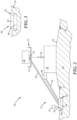
- the sluice 56 of FIG. 4 may be positioned between the waste liquid trench 22 and the cullet trench 42, alongside the cullet trench 42.
- the sluice 56 may be positioned alongside the cullet trench 42 on a side of the cullet trench 42 opposite that of the waste liquid trench 22.
- the sluice 56 may be positioned above and parallel to the cullet trench 42.
- the sluice 56 may replace the cullet trench 42.
- the waste molten glass chute 34 is positioned such that its downstream outlet transmits molten glass to the upstream inlet 62 of the sluice 56 and, more particularly, to the deflector 82 of the sluice 56.
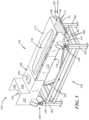
- FIGS. 5-14 illustrate another illustrative embodiment of a waste glass handling sluice 156.
- This embodiment is similar in many respects to the embodiment of FIG. 4 and like numerals between the embodiments generally designate like or corresponding elements throughout the several views of the drawing figures. Accordingly, the descriptions of the embodiments are hereby incorporated into one another, and description of subject matter common to the embodiments generally may not be repeated.
- the sluice 156 is elongate or oblong and extends along a longitudinal axis, and includes a base 158 configured to be carried on or by a forming floor of an architectural installation.
- the sluice 156 also includes a platform 160 carried above the base 158 and configured to convey waste glass from an upstream location to a downstream location, and also includes an upstream inlet 162 to receive hot molten glass, and a downstream outlet 164 to transmit cooled, preferably solidified, glass.
- the sluice 156 also may include one or more vibrators 166 ( FIG.
- vibration isolators 168 operatively coupled between the base 158 and the platform 160 to reduce transmission of vibrations outside of the sluice 156.
- the platform 160 includes an upper wall 170 to support, distribute, and convey glass in a downstream direction, and side walls 172 extending in a direction upwardly away from the upper wall 170 to guide and retain glass along and on the upper wall 170.
- the platform 160 also may include a cover 173 extending between the side walls 172 and spaced above the platform 160.
- the upper wall 170 has a plurality of apertures 174 to allow fluid to flow therethrough from a location below the upper wall 170 to a location above the upper wall 170.
- the apertures 174 convey fluid so as to cool and levitate molten glass and prevent adhesion of the molten glass to the upper wall 170 of the platform 160.
- the apertures 174 may facilitate provision of a cushion of gas on which the molten glass may be carried, and may include gas supplied on the platform at any pressure suitable to produce that cushion. It is also contemplated that gas pressure might not be applied and that the sluice 156 still may operate to one degree or another. Therefore, gas pressure may be applied through the apertures 174, for example, from 0 to 4 PSI (0 to 27.6 kPa) including all ranges, sub-ranges, values, and endpoints of that range.
- the platform 160 also includes one or more fluid ducts 176a,b,c coupled to a lower wall 178 of the platform 160 to communicate fluid to the plurality of apertures 174.
- the fluid duct(s) 176a,b,c communicate with a space between the upper wall 170, the lower wall 178 beneath the upper wall 170, and side walls 180 and end walls 181 extending therebetween.
- the walls 170, 178, 180, 181 may be welded together in an airtight manner.
- the upper wall 170 is welded to the side walls 180 and then the lower wall 178 is welded to the side walls 180.
- the fluid duct(s) 176a,b,c may be laterally offset from a longitudinally extending centerline of the sluice 156 to accommodate various structural elements of the vibratory equipment.
- the plurality of fluid ducts 176a,b,c beneath the upper wall 170 of the platform 160 can communicate fluid to the plurality of apertures 174 according to a plurality of different parameter values.
- an upstream fluid duct 176a may be supplied with a fluid at a first pressure and flow rate
- a downstream fluid duct 176c may be supplied with a fluid at a second pressure and flow rate, and so on.
- the apertures 174 corresponding to any given fluid duct of the plurality of fluid ducts 176a,b,c may be different in quantity and/or size to convey fluid according to different parameter values.
- the apertures 174 may be 1 mm to 5 mm in diameter including all ranges, sub-ranges, values, and endpoints of that range.
- the apertures 174 may be arranged in a rectangular array, as illustrated, or in any other suitable arrangement, and may be spaced apart from one another in longitudinal and lateral directions by 25 mm to 75 mm including all ranges, sub-ranges, values, and endpoints of that range.
- size, quantity, spacing, and configuration, of the apertures 174 and air pressure through the apertures 174 may be adjusted merely to achieve a fundamental minimum air velocity to provide enough force to lift glass off the surface like an air hockey puck, and such parameters may be depend on a mode of operation (receiving and conveying streams of molten glass or individual gobs of molten glass), and estimated weight of the glass.
- the fluid supplied to the platform 160 of the sluice 156 may be a gas or a liquid, for example, air or water, but can be any fluid suitable for use in cooling and/or conveying glass.
- the platform 160 may be composed of AISI 1018, 1020, 1065, and/or any other suitable carbon steel, 304 stainless steel, Inconel 601, and/or any other suitable metal, and/or any other material suitable for use with molten glass.
- the sluice 156 may be configured to receive process water with the molten glass, preferably the sluice 156 operates on a waterless basis such that it does not receive process water with the molten glass and, instead, receives "dry" molten glass and conveys the dry molten glass downstream. Accordingly, the sluice 156 may be waterless in one or more respects. Although not separately illustrated, those of ordinary skill in the art would recognize that the sluice 156 may be supplied with fluid using conduit, connectors, fans, pumps, controllers, valves, power supplies, and/or any other equipment suitable for use in supplying fluid to the sluice 156.
- the vibrators 66 may be supplied with electricity, or pneumatic or hydraulic fluid, via wiring, conduit, controllers, valves, and/or any other equipment suitable for use in supplying power and control to the vibrators 66.
- the upstream inlet 162 includes inlet side walls 192 on opposite lateral sides, an inlet front wall 194 extending between the side walls 192 at downstream ends of the side walls 192, and an inlet rear wall 196 that may have an upper edge that is vertically recessed from corresponding upper edges of the side walls 192 and front wall 194.
- the inlet rear wall 196 may be shorter than the side walls 192, for example, to accommodate a molten glass chute (not shown) cooperating with the sluice 156 to deliver molten glass to the inlet 162.
- the inlet 162 also includes a bottom wall 198 extending between the side walls 192 and supporting the platform 160 thereon, and a top wall 200 extending between the side walls 192 and forward from the front wall 194.
- the top wall 200 has an aperture 202 that may be configured to be coupled to steam removal conduit and a corresponding pump, fan, and/or any other equipment (not shown) suitable to pull air and steam out of the sluice 156.
- the base 158 may include a rectangular frame that may include four or more legs or pedestals 204 at each corner of the base 158, longitudinally extending side rails 206 extending between the pedestals 204, and laterally extending end rails 208 extending between the pedestals 204.
- the sluice 156 may be equipped with one or more sensors 209, for example, proximate the outlet 164 of the sluice 156 to sense presence of glass, temperature of the glass, and/or any other characteristics suitable for use as feedback in adjusting performance characteristics of the sluice 156 such as air flow, air pressure, vibration frequency, vibration intensity, and/or the like.
- the sensor(s) 209 may include an IFM TW2000 infrared sensor to measure temperature of the glass as it exits the sluice 156.
- the sluice 156 can be coupled to any suitable controllers, which, in turn, may be coupled to the vibrators, fans, pumps, power supplies, and/or any other equipment used to operate the sluice 156 and which may be coupled to and controlled by such controllers.
- the cradle 157 is carried by the base 158 and, in turn, carries the sluice 156.
- the cradle 157 includes a base wall 210, rear flanges 212 extending laterally outwardly from the base wall 210 at a rear end of the cradle 157, and front flanges 214 extending laterally outwardly from the base wall 210 at a front end of the cradle 157.
- the flanges 212, 214 may extend upwardly along the sidewalls 172 of the sluice 156 to laterally restrain the sluice 156 and may be welded, fastened, or otherwise coupled thereto.
- the cradle 157 also includes one or more webs 216 ( FIGS. 11 and 12 ) extending downwardly from and longitudinally along the base wall 210 and may be welded, fastened, or otherwise coupled thereto.
- the cradle 157 further includes one or more crossmembers 217 that extends laterally between the webs 216 and that may be welded, fastened, or otherwise coupled thereto.
- the cradle 157 further includes a vibrator mounting plate 218 that may be welded, fastened, or otherwise coupled to upstream ends of the webs 216 for mounting the vibrators 166 thereto, and a reinforcement strut 220 that may be welded, fastened, or otherwise coupled to the base wall 210, and to the vibrator mounting plate 218 and extending upstream therefrom to a rear wall 222, which may be welded, fastened, or otherwise coupled to and extending downwardly from the base wall 210 at the rear end of the cradle 157.
- the vibrators 166 may be fastened, welded, or otherwise coupled to the mounting plate 218 in any suitable manner.
- the sluice 156 may be suspended from overhead, for example, from girders, trusses, and/or any other suitable overhead structure of a building in which the sluice 156 is used.
- suitable tie rods, cables, and/or the like, along with corresponding fasteners, brackets, and/or the like may be used to couple the cradle 157 to such building overhead structure.
- the vibration isolators 168 may be configured to be coupled between such overhead structure and the cradle 157 in any suitable manner.
- the sluice 156 and its ancillary equipment like the sensor(s) 209, a fluid fan or pump to supply fluid through the apertures 174, and the vibrators 166 may be instrumented and/or communicated with one or more controllers for closed loop control of rate of flow of molten glass through the sluice 156.
- a temperature of the glass can be sensed or monitored by one or more of the sensors 209, for example, at or proximate the end of the platform 160 as it exits the sluice 156.
- the vibration energy can be decreased to slow the glass flow rate across or along the platform thereby allowing more time for the glass to cool down more, and/or, in another example, air pressure supplied through the apertures 174 can be increased to increase cooling of the glass.
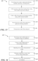
- FIG. 15 illustrates an example of a method 300 for handling glassware manufacturing waste using the glassware manufacturing system 10 and glassware manufacturing waste handling system 12 described herein.
- method 300 will be described in the context of the glassware manufacturing system 10 described above and generally illustrated in FIGS. 1 through 14 . It will be appreciated, however, that the application of the present methodology is not meant to be limited solely to such an arrangement, but rather method 300 may find application with any number of arrangements (i.e., steps of method 300 may be performed by components of the glassware manufacturing system 10 other than those described below, or arrangements of the glassware manufacturing system 10 other than that described above).
- Method 300 comprises a step 310 of providing process water to the glassware forming machine 16 carried by the forming floor 18, where the process water drains from the glassware forming machine 16 to the forming floor 18.
- providing process water may include providing plant water, cullet water, shear spray water, cooling water to the waste molten glass chute 34, and/or any other liquid to the glassware forming machine 16.
- process water can be provided to the glassware forming machine 16 by way of spray nozzles or other devices for use as shear water (e.g., to cool shears), cooling water (e.g., to cool the waste molten glass chute 34), and so forth.
- the process water can be provided to the glassware forming machine 16 and can then drain by gravity from the glassware forming machine 16 to the forming floor 18.
- the provided process water can be recycled from water previously used in a glassware manufacturing process, and may be treated and recycled from the sump pit 28.
- Method 300 comprises a step 320 of collecting the process water from the forming floor 16 using a waste liquid trench 22 and a sump pit 28 formed in the forming floor 16. After the process water drains from the glassware forming machine 16 to the forming floor 18, the water can flow to the waste liquid trench 22. In instances when the forming floor 16 has a pitch or is sloped or crowned, the pitch, slope or crown of the forming floor 16 can assist with providing and directing the process water flow. As the water flows to and is collected by the water liquid trench 22, the water liquid trench 22 can carry and direct the water to the sump pit 28, where the water can be collected and contained for treatment, further use and recycling, and/or disposal. In some instances, collecting the water can include collecting the water from other equipment in addition to the glassware forming machine 16, for example the cullet material handler 30.
- Method 300 comprises a step 330 of collecting cullet from the glassware forming machine 16.
- the method includes using the cullet material handler 30 to collect the cullet, where the cullet material handler 30 is disposed adjacent, or proximate, to the glassware forming machine 16.
- the cullet can be provided to the cullet material handler 30 using the waste molten glass chute 34, a reject conveyor 36, and/or other equipment used in the industry for handling cullet.
- the method also or instead includes using the sluice 56, 156 to collect the cullet, where the sluice 56, 156 is disposed adjacent, or proximate, to the glassware forming machine 16.
- the cullet can be provided to the sluice 56, 156 using the waste molten glass chute 34, a reject conveyor 36, and/or other equipment used in the industry for handling cullet.
- Method 300 comprises a step 340 of recycling the process water from the sump pit 28 to the glassware forming machine 16.
- the water in the sump pit 28 can be pumped/provided to the glassware forming machine 16 using a pump (not shown) or other means.
- the water can be pumped through plumbing to the glassware forming machine 16 including at least one spray nozzle.
- additional water can be added to the process water for compensating for process water losses, for example due to evaporation.
- the glassware manufacturing system 10 can be generally a closed loop with regard to providing the recycled process water.
- method 300 may comprise a step 350 of treating the process water from the sump pit 28.
- Process water collected by the sump pit 28 may include materials and/or debris (e.g., oil, dirt, small glass pieces, suspended solids, and the like) from the glassware forming process that may be undesirable. In these cases, the collected process water may be treated so that cleaner water may be recycled to the glassware forming machine 16.
- the sump pit 28 may include an API oil-water separator. Treating the process water with an API oil-water separator can include separating gross amounts of oil and/or suspended solids from the collected water. Other methods for treating the process water may include filtration using a filter. It is contemplated that the water collected by the sump pit 28 may be treated using other equipment and processes.
- FIG. 16 illustrates an example of a method 400 for handling waste molten glass using the sluices 56, 156 and their ancillary equipment described herein.
- method 400 will be described in the context of the sluices 56, 156 generally illustrated in FIGS. 4-14 . It will be appreciated, however, that the application of the present methodology is not meant to be limited solely to such an arrangement, but rather method 400 may find application with any number of arrangements (i.e., steps of method 400 may be performed by components of the sluices 56, 156 and ancillary equipment other than those described below, or arrangements of the sluices 56, 156 and ancillary equipment other than that described above).
- Method 400 comprises a step 410 of receiving waste molten glass on a cushion of gas on a platform.
- a cushion of gas on a platform For example, discrete gobs or charges of waste molten glass, or streams of waste molten glass may be received on cushions of gas supplied by the platforms 60, 160 illustrated in FIGS. 4 and 5 , or on any other platform suitable to have a cushion of gas thereon and to receive molten glass thereon.
- Method 400 also comprises a step 420 of conveying waste molten glass in a downstream direction on a cushion of gas on a platform.
- the platforms 60, 160 may be declined along a downstream direction, and the cushion of gas may be configured to push the molten glass in a downstream direction.
- Method 400 further comprises a step 430 of adjusting one or more characteristics of gas to affect a flow of waste molten glass along a platform.
- the gas can be supplied at an upstream end of the platforms 60, 160 at a higher pressure and/or flow rate compared to gas supplied at a downstream end of the platforms 60, 160.
- Method 400 also comprises a step 440 of vibrating a platform to assist with conveying waste molten glass in a downstream direction.
- the platforms 60, 160 may be coupled to the one or more vibrators 66, 166 to produce relative movement in an lateral and/or longitudinal direction between an upper surface of the platforms 60, 160 and a lower surface of the molten glass.
- Method 400 additionally comprises a step 450 of adjusting one or more characteristics of vibration of step 440 to affect a flow of waste molten glass along a platform.
- a temperature of the glass can be sensed or monitored by one or more of the sensors 209, for example, at or proximate the end of the platform 160 as it exits the sluice 156.
- the vibration energy can be decreased to slow the glass flow rate across or along the platform thereby allowing more time for the glass to cool down more, and/or, in another example, air pressure supplied through the apertures 174 can be increased to increase cooling of the glass.
- the presently disclosed equipment and/or methods may facilitate reception and conveying of hot molten glass in a manner that may eliminate the need for a basement, may be compact, may be waterless, and/or may reduce or eliminate chute-clogging of waste glass.
- FIG. 17 illustrates a prior art glassware manufacturing system, including an architectural installation having a forming floor and a basement beneath the forming floor.
- a glassware forming machine is carried on the forming floor, and an annealing lehr is carried on the forming floor downstream of the forming machine.
- a forehearth is located above the forming machine and is coupled to a molten glass feeder configured to provide glass gobs to the glassware forming machine.
- a glassware manufacturing waste handling system includes a hot gob chute extending from the feeder, through the forming floor, and into a gondola in the basement, and a shear spray collection pan for dumping shear spray into the basement via the hot gob chute or otherwise.
- the waste handling system also includes a hot cullet return chute extending from a hot container conveyor, through the forming floor, and into a gondola in the basement, and a cold cullet return chute extending from a cold container conveyor, through the forming floor, and into another gondola in the basement.
- the waste handling system also includes floor drains extending from an upper surface of the forming floor to the basement for draining waste liquids onto the basement floor and into an American Petroleum Institute (API) pit for oil/water separation.
- API American Petroleum Institute
- a glassware manufacturing system 10 comprising:
- the glassware forming machine 16 is an individual section machine.
- system as described above, further comprising: an enclosure 44 over the cullet trench 42 to establish a cullet trench conduit 46; and steam removal ductwork 32 in fluid communication with the cullet trench conduit 46 to remove steam from the cullet trench conduit 46.
- system as described above, further comprising: an annealing lehr 40 downstream of the glassware forming machine 16.
- system as described above, further comprising: a cold cullet return conveyor 48 on the forming floor 18 configured to receive cold glassware rejects from a location downstream of the annealing lehr 40.
- system as described above, further comprising: a reject conveyor 36 configured to transport the hot glassware rejects from the glassware forming machine 16 to the cullet material handler 30.
- reject conveyor 36 includes an air assist plate.
- reject conveyor 36 includes high temperature plating.
- system as described above, further comprising: a cullet crusher 50 on the forming floor 18.
- an operator pitch chute 52 with bottle crushing equipment 54 configured to receive hot glassware rejects from the glassware forming machine 16.
- a waste molten glass chute 34 configured to direct rejected mold charges from the glassware forming machine 16 to the cullet material handler 30 and/or the molten waste glass sluice 56.
- a glassware manufacturing waste handling system 10 comprising:
- the glassware manufacturing waste handling system as described above, wherein liquid waste collected by the sump pit 28 is recycled to a glassware manufacturing system 16.
- a method for handling glassware manufacturing waste comprising:
- the method for handling glassware manufacturing waste as described above further comprising: treating 350 the process water from the sump pit 28.
Landscapes
- Chemical & Material Sciences (AREA)
- Engineering & Computer Science (AREA)
- Materials Engineering (AREA)
- Organic Chemistry (AREA)
- Manufacturing & Machinery (AREA)
- Mechanical Engineering (AREA)
- Physics & Mathematics (AREA)
- Fluid Mechanics (AREA)
- Processing Of Solid Wastes (AREA)
- Re-Forming, After-Treatment, Cutting And Transporting Of Glass Products (AREA)
- Organic Low-Molecular-Weight Compounds And Preparation Thereof (AREA)
- Glass Melting And Manufacturing (AREA)
Abstract
Description
- This patent application discloses systems and methods for glassware manufacturing and, more particularly, a system for handling glassware manufacturing waste.
- Glass container manufacturing processes can include using a glassware forming machine to shape and form glass containers from molten glass. During the forming process, a stream of the molten glass can be separated into a glass gob, formed into a parison, and shaped into a container. Additionally, the glass gobs, parisons, containers, or pieces thereof may be rejected due to various reasons. These rejected materials, along with streams of molten waste glass, are known as internal cullet and can be recycled to a glass melter to produce molten glass.
- The present disclosure embodies a number of aspects that can be implemented separately from or in combination with each other.
- A glassware manufacturing system, in accordance with one aspect of the disclosure, comprises an architectural installation having a forming floor and no basement beneath the forming floor; a glassware forming machine carried on the forming floor; a molten glass feeder configured to provide molten glass to the glassware forming machine; and a glassware manufacturing waste handling system, including: a sump pit in the forming floor; a waste liquid trench substantially surrounding the glassware forming machine and flowing to the sump pit; and at least one of a cullet material handler or a molten waste glass sluice, configured to receive molten glass from the molten glass feeder and hot glassware rejects from the glassware forming machine. In some instances, the glassware manufacturing system may include an enclosure over the cullet trench, steam removal ductwork, an annealing lehr, a cold cullet return conveyor, a reject conveyor, a cullet crusher, a molten glass chute, and/or an operator pitch chute.
- A glassware manufacturing waste handling system, in accordance with one aspect of the disclosure, comprises a sump pit in a forming floor of an architectural installation, where the architectural installation has no basement beneath the forming floor; a waste liquid trench substantially surrounding a glassware forming machine carried on the forming floor, the waste liquid trench flowing to the sump pit; and at least one of a cullet material handler or a molten waste glass sluice, configured to receive molten glass from a molten glass feeder and hot glassware rejects from the glassware forming machine.
- A method for handling glassware manufacturing waste, in accordance with one aspect of the disclosure, comprises providing process water to a glassware forming machine carried by a forming floor, where the process water drains from the glassware forming machine to the forming floor; collecting the process water from the forming floor using a waste liquid trench and a sump pit formed in the forming floor; collecting cullet from the glassware forming machine using at least one of a cullet material handler or a molten waste glass sluice disposed adjacent to the glassware forming machine; and recycling the process water from the sump pit to the glassware forming machine. In some implementations, the method may include treating the process water from the sump pit.
- A molten waste glass handling sluice, in accordance with another aspect of the disclosure, extends along a longitudinal axis, and includes a base; a platform carried above the base and including an upper wall having a plurality of apertures to deliver fluid from a location below the upper wall to a location above the upper wall; side walls extending in a direction upwardly away from the upper wall; an upstream inlet to receive hot molten glass; and a downstream outlet to transmit cooled glass.
- A method of handling waste molten glass, in accordance with a further aspect of the disclosure, comprises receiving waste molten glass on a cushion of gas on a platform, and conveying the waste molten glass in a downstream direction on the cushion of gas on the platform. This method also may include vibrating the platform to assist with conveying the waste molten glass in the downstream direction, adjusting one or more characteristics of the vibrating to affect a flow of the waste molten glass along the platform, and/or adjusting one or more characteristics of the gas to affect a flow of the waste molten glass along the platform.
- The disclosure, together with additional objects, features, advantages and aspects thereof, will be best understood from the following description, the appended claims and the accompanying drawings, in which:
-
FIG. 1 is a schematic top plan view of a glassware manufacturing system and a glassware manufacturing waste handling system, according to an illustrative embodiment of the present disclosure; -
FIG. 2 is a schematic side view of the glassware manufacturing system and glassware manufacturing waste handling system shown inFIG. 1 ; -
FIG. 3 is a schematic cross-sectional view illustrating a cullet material handler, an enclosure, and a cullet trench utilized in the glassware manufacturing system shown inFIG. 1 ; -
FIG. 4 is a schematic, fragmentary, isometric view of a waste glass handling sluice according to an illustrative embodiment of the present disclosure; -
FIG. 5 is a schematic, fragmentary, isometric view of another waste glass handling sluice according to another illustrative embodiment of the present disclosure, wherein the sluice is carried by a cradle on a platform; -
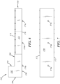
FIG. 6 is a side view of the sluice ofFIG. 5 ; -
FIG. 7 is a bottom view of the sluice ofFIG. 5 ; -
FIG. 8 is a top view of a platform of the sluice ofFIG. 5 ; -
FIG. 9 is a side view of the platform shown inFIG. 8 ; -
FIG. 10 is an enlarged cross-sectional view of the platform shown inFIG. 8 , taken along line 10-10 ofFIG. 9 ; -
FIG. 11 is a side view of the sluice, cradle, and platform ofFIG. 5 ; -
FIG. 12 is a front end view of the sluice, cradle, and platform ofFIG. 5 ; -
FIG. 13 is a top view of the sluice, cradle, and platform ofFIG. 5 ; -
FIG. 14 is a bottom view of the sluice, cradle, and platform ofFIG. 5 ; -
FIG. 15 is a flow diagram showing various steps of an illustrative embodiment of a method for using the glassware manufacturing system, the glassware manufacturing waste handling system, and the components thereof shown inFIGS. 1 through 14 ; -
FIG. 16 is a flow diagram showing various steps of another illustrative embodiment of a method and for using the glassware manufacturing system, the glassware manufacturing waste handling system, and the components thereof shown inFIGS. 1 through 14 ; and -
FIG. 17 is a glassware manufacturing system according to the prior art. - In accordance with at least one aspect of the disclosure, a glassware manufacturing system contains and recycles process water within the system, limits internal cullet handling to a forming floor, and minimizes the volume and improves the quality of process water, thereby reducing environmental disposal costs and improving safety in a glassware forming area. External cullet arises from post-consumer recycling of glass products. Internal cullet arises from waste glass in a glass factory, including waste gobs or charges of molten glass from a gob or charge feeder spout, or streams of molten glass from a glass melter, a finer, a forehearth, or the gob or charge feeder spout, or hot glassware rejects, or cold glassware rejects.
- Conventional glassware forming systems often combine manual or semi-automatic methods for handling glass cullet (e.g., steel hoppers, drag chains into bunkers, fork trucks, and the like) in a basement under glassware forming machines. The forming systems can include a system that allows process water and/or other material to gravity flow through collection pans, pipes, and chutes onto the basement floor and into an API oil-water separator pit. Oils and grease can be skimmed from the collected process water, and the remaining process water can be recycled back into the system. As part of this process, some process water may escape the basement with the cullet and has the potential to be comingled with storm or other water. This requires collection and conveyance of the escaped water back to the basement, where increased water volumes, due to comingling with storm water, can upset the system water balance and result in excess water that must be hauled off for environmental disposal at extra expense.
- Consequently, the present disclosure is directed to a glassware manufacturing system, and a glassware manufacturing waste handling system that includes an automated and closed cullet and cullet water handling system. By using the systems and methods disclosed herein, the glassware manufacturing system can be contained within a production building without a basement. Additionally, the cullet, process, and/or shear water can be collected and recycled within the system to minimize cost from environmental disposal, and cullet handling can be limited to the forming floor.
- Referring generally to
FIGS. 1 through 3 , aglassware manufacturing system 10 and glassware manufacturingwaste handling system 12 are shown in accordance with an illustrative embodiment of the present disclosure. Theglassware manufacturing system 10 can comprise anarchitectural installation 14, aglassware forming machine 16 carried on a formingfloor 18 of theinstallation 14, aglass furnace forehearth 20, and a glassware manufacturingwaste handling system 12. Although not shown, thesystem 10 also may include a submerged combustion melting (SCM) furnace or "melter" and a molten glass finer between the melter and theforehearth 20. - Additionally, the
architectural installation 14 can include a concrete foundation establishing the formingfloor 18. Thearchitectural installation 14 may also include a factory building (not shown) on the foundation including walls, a roof, and/or an upper level or raised platform above the formingfloor 18. Thearchitectural installation 14 can be configured to support and shelter a compact, single-levelglassware manufacturing system 10. For example, thearchitectural installation 14 can be configured to carry glassware forming equipment. - In the embodiment shown in
FIGS. 1 and2 , thearchitectural installation 14 has no basement beneath the formingfloor 18 as utilized in conventional systems. In conventional glassware forming systems, a basement is required because traditional cullet chutes use large amounts of high pressure water to keep the steel chutes cool and maintain the flow of rejected or streaming glass into a basement, where the water and cullet are collected. Generally, the level of the water and cullet collecting equipment has been at least one full level below a forming machine. However, utilizing a basement may be less efficient compared to implementing theglassware manufacturing system 10 disclosed herein because using theglassware manufacturing system 10 can reduce the amount of capital investment needed, allow for reductions in process equipment labor requirements, and increase up-time across the glassware forming process. As used herein, the term "basement" includes the lowest habitable level of the glass factory below a forming floor of the factory and can include a first level or a below grade or below ground level portion that may require excavation of earthen material. In contrast, according to the present disclosure, no basement is required, such that thearchitectural installation 14 includes a concrete slab with earthen material directly underneath the slab, wherein the slab establishes the formingfloor 18. - In some embodiments, and with reference to
FIG. 2 , the formingfloor 18 can be sloped to direct process water and/or other liquids on the formingfloor 18 away from process equipment. In the context of this disclosure, process water may include shear spray water, cooling water, cullet water, quench water, and the like. For example, the formingfloor 18 can be sloped away from aglassware forming machine 16 to awaste liquid trench 22. The formingfloor 18 can be sloped or crowned such that liquid efficiently flows but does not create a safety hazard within theglassware manufacturing system 10. It is contemplated that the formingfloor 18 may be sloped or crowned just enough to facilitate runoff of liquids, like water, lubricants, or the like. - With continued reference to
FIG. 2 , theglassware manufacturing system 10 can include theglassware forming machine 16 carried on the formingfloor 18. Theglassware forming machine 16 can include a machine that holds and moves molten glass, often in the form of a glass gob, and shapes the molten glass to form glassware (e.g., containers). In one example, theglassware forming machine 16 may include an individual section (IS) machine comprising a bank of identical sections, each of which contains a complete set of equipment to form a glass container. The sections may be in a row and may be fed molten glass from a forehearth and moving chutes. Theglassware forming machine 16 can be completely housed by thearchitectural installation 14. It will be appreciated that other types of forming machines may be used in theglassware manufacturing system 10. - The
glassware manufacturing system 10 can include aglass furnace forehearth 20 having amolten glass feeder 24 configured to providemolten glass 26 to theglassware forming machine 16. Theglass furnace forehearth 20 can be located downstream of a melting furnace (not shown) and may be part of a hot-end subsystem. Theglass furnace forehearth 20 can receive molten glass from the furnace and cool the molten glass to a uniform temperature and viscosity suitable for downstream forming operations. - With continued reference to
FIG. 2 , themolten glass feeder 24 can be located at a downstream end of theglass furnace forehearth 20 and is configured to produce molten glass portions. In the illustrated embodiment, themolten glass feeder 24 can receive the molten glass from theglass furnace forehearth 20, produce a continuous stream of molten glass, and separate the stream into discrete glass gobs that freefall into gob handling equipment (not shown), which may include a series of distributors, scoops, chutes, deflectors, and funnels. The gob handling equipment may also include ancillary lubrication equipment to apply lubricants to the gob handling equipment and liquid separators to separate or otherwise process the lubricants. Themolten glass feeder 24 and gob handling equipment can be configured to provide glass gobs to theglassware forming machine 16. - In another embodiment, not presently illustrated, the
molten glass feeder 24 can receive the molten glass from theglass furnace forehearth 20, produce a continuous stream of molten glass that that is fed downwardly into a molten glass transport cup and thereafter severed to produce a discrete portion of molten glass carried in the cup and separated from the molten glass stream. In this embodiment, the glass-filled cup is thereafter moved to theglassware forming machine 16, over a mold, and either inverted to dump the glass in the mold, split open to dump the glass in the mold, or opened at an openable bottom end to dump the glass in the mold. - In a further embodiment, not presently illustrated, the
molten glass feeder 24 can receive the molten glass from theglass furnace forehearth 20, produce a continuous stream of molten glass that is directly injected into an inverted mold, and then severed to produce a discrete portion of molten glass carried in the cup and separated from the molten glass stream. In this embodiment, no gob handling equipment and no molten glass cup are used; instead, the molten glass is delivered directly into the mold. - Accordingly, the terminology "molten glass portion" includes a molten glass gob, gather, stream, chunk, charge, mold charge, and the like. In one example, a molten glass portion may include a molten glass gob cut from a stream of molten glass produced by a gob feeder and then dropped into gob handling equipment, a transport cup, or a mold. In other examples, a molten glass portion may include a stream of molten glass delivered from an upstream continuous supply of molten glass, and thereafter separated from the upstream continuous supply of molten glass in any suitable manner.
- Additionally, and with reference to
FIGS. 1 and2 , theglassware manufacturing system 10 can include the glassware manufacturingwaste handling system 12, which can further include a shear spray collection system 13 (FIG. 1 ), a sump pit 28 (FIG. 2 ), thewaste liquid trench 22, and acullet material handler 30. The glassware manufacturingwaste handling system 12 can be used to remove, handle, and/or recycle process liquid, for example, water, oil, and other materials, used during forming processes, and for removing cullet and glassware rejects. - As illustrated in
FIG. 1 , the glassware manufacturingwaste handling system 12 can include thesump pit 28 in the formingfloor 18. Thesump pit 28 can include a pit or lowest-most volume in the formingfloor 18 for collecting the process water and other liquid resulting from the forming process. When the formingfloor 18 is sloped or crowned, thesump pit 28 can be located at a low portion of the formingfloor 18 so that the liquid can generally flow from theglassware forming machine 16 and equipment to thesump pit 28. Thesump pit 28 may include means, for example a pump (not shown), for further transferring the liquid for treatment and/or other handling. For example, the liquid waste in thesump pit 28 can be transferred for treatment, for example, using a pump, and then can be recycled. In some instances, thesump pit 28 may include an oil-water separator (e.g., an API oil-water separator) and/or other treatment means. In this way, theglassware manufacturing system 10 can include a closed or open recirculating loop for treating and/or recycling the process water and other liquid, which can contribute to reducing human intervention in the forming process and potential negative environmental impact while improving safety and process stability. - The glassware manufacturing
waste handling system 12 can include awaste liquid trench 22 substantially surrounding theglassware forming machine 16 and flowing to thesump pit 28. As used herein, the phrase "substantially surround" means extending between 240 and 360 angular degrees around including all ranges, sub-ranges, and values including endpoints of that range. Thewaste liquid trench 22 can be carried by and integrally formed in the formingfloor 18. When the formingfloor 18 is sloped, the liquid can fall onto the formingfloor 18 from theglassware forming machine 16, flow down the sloped formingfloor 18 to thewaste liquid trench 22, and flow through thewaste liquid trench 22 to thesump pit 28. InFIG. 1 , thewaste liquid trench 22 forms a rectangle and completely surrounds theglassware forming machine 16. It will be appreciated that thewaste liquid trench 22 may include other configurations and may include more than one trench that flows to thesump pit 28. For example, thewaste liquid trench 22 may also substantially surround and/or be located adjacent to other equipment within theglassware manufacturing system 10, for examplesteam removal ductwork 32. - Shown in
FIG. 1 , the glassware manufacturingwaste handling system 12 can include thecullet material handler 30 configured to receive discrete molten glass portions and unused molten glass streams from themolten glass feeder 24. Although not illustrated, thehandler 30 also may be configured to receive molten glass streams from the SCM furnace and/or the finer when it is desired to drain or "dump" molten glass therefrom, for example, to accommodate a glass color changeover, equipment maintenance, equipment relocation, or the like. Any suitable conduit, sluice, or the like may be used to communicate drains, outlets, or the like of the SCM furnace and/or the finer to thehandler 30. Thehandler 30 is also configured to receive hot glassware rejects from theglassware forming machine 16, cold glassware rejects from a coldcullet return conveyor 48, and the like. Thecullet material handler 30 may include a cullet drag chain, which may include a chain conveyor comprising a continuous chain arrangement with a series of single pendants, where the chain arrangement can be driven by a motor to convey the rejected molten glass portions, the unused molten glass streams, the cold glassware rejects, and/or the hot glassware rejects. In an example, the cullet drag chain can include a stainless steel hinged drag chain that is suitable for exposure to heat and a humid environment. It is contemplated that thecullet material handler 30 can include other types of conveyors configured to handle hot glass and glass cullet, for example a belt conveyor, a pneumatic conveyor, and/or any other type of material handler suitable for use in moving cullet. - In the illustrated example of
FIG. 2 , as themolten glass feeder 24 distributes glass gobs to theglassware forming machine 16, some of the glass gobs may be rejected due to commercial variations. At least some of the rejected glass gobs may be transferred from themolten glass feeder 24 and/or theglassware forming machine 16 to thecullet material handler 30 by way of a waste moltenglass chute 34. The waste moltenglass chute 34 may include a chute or sloping channel or enclosure through which rejected mold charges can fall and be directed to thecullet material handler 30. The waste moltenglass chute 34 may include material suitable for handling high temperatures and/or corrosion. In some instances, the waste moltenglass chute 34 may be enclosed and/or cooled. - Additionally, and with reference to
FIG. 2 , as theglassware forming machine 16 forms the glassware, some of the hot glassware may be rejected due to commercial variations. Areject conveyor 36 can be configured to transport hot glassware rejects from theglassware forming machine 16 and/or aglassware conveyor 38 to thecullet material handler 30. Thereject conveyor 36 can be located downstream from theglassware forming machine 16 and upstream from anannealing lehr 40. Thereject conveyor 36 may include a belt conveyor, a chain conveyor, and the like. In some instances, thereject conveyor 36 may be covered and/or enclosed for containing the cullet to thereject conveyor 36. Additionally, thereject conveyor 36 may include an air assist plate and/or may include high temperature plating. When glassware from theglassware forming machine 16 is rejected, the rejected glassware can be blown from theglassware conveyor 38 and to thereject conveyor 36 upstream from theannealing lehr 40. - A
cullet trench 42 may be formed integrally and within the formingfloor 18 and may be located proximate to theglassware forming machine 16. As used herein, the term "proximate" means between two inches and twenty feet including all ranges, sub-ranges, endpoints, and values of that range. In specific examples, thecullet material handler 30 can be partially recessed in thecullet trench 42 or can be fully recessed in thecullet trench 42. Placing thecullet material handler 30 at least partially recessed in acullet trench 42 can improve access and safety around theglassware forming machine 16. In some instances, thecullet material handler 30 may be mounted to and disposed at or above a level of the formingfloor 18. - With reference to
FIG. 3 , thecullet material handler 30 can include anenclosure 44 over thecullet trench 42 to establish acullet trench conduit 46. Theenclosure 44 can include a cover (e.g., stainless steel cover) that covers at least the top portion of thecullet material handler 30 and can be configured to contain glass cullet to thecullet material handler 30 and contain steam within thecullet trench conduit 46. The steam may be produced from water-cooling jackets, evaporated process water, and from other forming processes. - With reference to
FIGS. 1 and2 ,steam removal ductwork 32 can be in fluid communication with thecullet trench conduit 46 to remove the steam from thecullet trench conduit 46. Thesteam removal ductwork 32 can include ducting (e.g., stainless steel sheet metal and the like) and/or other conduit that couples to theenclosure 44 and/or steam removal fans (not shown) for moving the steam and/or other gases from thecullet trench conduit 46 to outside theglassware manufacturing system 10. It will be appreciated that thesteam removal ductwork 32 can include other materials that may be suitable for high-temperature and/or corrosive environments. Removing the steam can serve to improve system safety by improving visibility. - With reference to
FIG. 2 , the shearspray collection system 13 can include ashear spray collector 15 under thefeeder 24 to collect shear spray water. In one embodiment, theshear spray collector 15 may include a funnel, tray, or pan that may be in fluid communication with the cullet trench, for example, via the mold charge chute. In another embodiment, the shearspray collection system 13 may be independent from the cullet quench water collection equipment such that shear spray water can be processed and recycled independently of the cullet quench water. - In some implementations, and with reference to
FIG. 1 , anannealing lehr 40 can be disposed downstream of theglassware forming machine 16 and can be configured for annealing glassware formed by theglassware forming machine 16. Theannealing lehr 40 can include a gas-fired oven where theglassware conveyor 38 transports glassware from theglassware forming machine 16 and extends longitudinally through the oven. Additionally, a pusher (not shown) can be configured to push long, transversely extending rows of glassware into theannealing lehr 40. - The
glassware manufacturing system 10 can include a coldcullet return conveyor 48 configured to receive cold glassware rejects and cullet from theglassware conveyor 38 and/or alehr reject conveyor 41 at a location downstream from theannealing lehr 40. The lehr rejectconveyor 41 and/or the coldcullet return conveyor 48 may include a belt conveyor, a chain conveyor, and/or another type of conveyor suitable for conveying the cold glassware rejects and cullet to thecullet material handler 30. - The
glassware manufacturing system 10 may include acullet crusher 50 on the formingfloor 18 and disposed between thecullet material handler 30 and the coldcullet return conveyor 48. Thecullet crusher 50 can be configured to crush and further break rejected glassware and cullet received from the coldcullet return conveyor 48 and can direct the resulting cullet to thecullet material handler 30. Thecullet crusher 50 can include, for example, a high speed rotor with wear resistant tips and a crushing chamber, which the rejected glassware can be thrown against. It is contemplated that other types of cullet crushers may be used in theglassware manufacturing system 10, for example, a cylinder/piston impact crusher, hammer mill, rotating breaker bars, rotating drum and breaker plate, or the like. - In some implementations, the
glassware manufacturing system 10 may include anoperator pitch chute 52 withbottle crushing equipment 54 configured to receive hot glassware rejects from theglassware forming machine 16. Theoperator pitch chute 52 and/or thebottle crushing equipment 54 can be disposed adjacent, or proximate, to theglassware forming machine 16. Glassware rejected by an operator can be placed into theoperator pitch chute 52 and crushed by thebottle crushing equipment 54. Thebottle crushing equipment 54 may include a bottle or cullet crusher, and the resulting cullet can be recycled. Similar to thecullet crusher 50, thebottle crushing equipment 54 may include a high speed rotor and a crushing chamber for crushing the rejected glassware to form glass cullet, and/or any other suitable crushers. - With reference to
FIG. 4 , a wasteglass handling sluice 56 is provided to receive molten glass gobs and/or streams at an upstream location, and cool and convey such molten glass to a downstream location, for example, in solidified form. In one example, hot molten glass may be received at a temperature in the range of 1300 to 1100 degrees Celsius and may be conveyed at a temperature in the range of 1100 to 600 degrees Celsius, and may be discharged from the equipment at a temperature in the range of 600 to 450 degrees Celsius. - In the illustrated embodiment, the
sluice 56 is configured to be carried on an upper surface of a forming floor or in a shallow trench in the upper surface of the forming floor. Therefore, the location of thesluice 56 represents a significant departure from conventional arrangements wherein waste molten glass is conveyed down through a forming floor and into a water tank in a basement beneath the forming floor. Nonetheless, in other embodiments, thesluice 56 could be located in the basement of a conventional glass factory architectural installation. In any case, the construction and arrangement of thesluice 56 represents a significant departure from conventional waste molten glass quenching tanks, as described below. - The
sluice 56 extends along a longitudinal axis, and includes a base 58 configured to be carried on or by a forming floor of an architectural installation, and a table orplatform 60 carried above the base and configured to convey waste glass from an upstream location to a downstream location. Thesluice 56 also includes anupstream inlet 62 to receive hot molten glass, and adownstream outlet 64 to transmit cooled, preferably solidified, glass. Thesluice 56 also may include vibrators 66 operatively coupled to theplatform 60 to vibrate theplatform 60 for assisting with moving waste glass in a downstream direction, andvibration isolators 68 operatively coupled between the base 58 and theplatform 60 to reduce transmission of vibrations outside of thesluice 56. - The base 58 may include a rectangular frame, as illustrated, and may be fastened or otherwise coupled directly to the forming floor. In other embodiments, the
base 58 may include four or more pedestals; one at each corner of the sluice platform. In any embodiment, thebase 58 may be adjustable to adjust an angle of declination of theplatform 60. For example, thebase 58 may include adjustable legs 59, which may include feet, rollers, wheels, or the like, between the forming floor on the one hand and corners of the frame or the pedestals on the other, to raise or lower one or more corners of thesluice platform 60. - The
platform 60 includes anupper wall 70 to support, distribute, and convey glass in a downstream direction, and side walls 72 extending in a direction upwardly away from theupper wall 70 to guide and retain glass along and on theupper wall 70. Theplatform 60 also may include acover 73 extending between the side walls 72 and spaced above theplatform 60, and also the steam removal ductwork and related equipment described above with respect toFIGS. 1 and2 . Theupper wall 70 has a plurality ofapertures 74 to allow fluid to flow therethrough from a location below theupper wall 70 to a location above theupper wall 70. Theapertures 74 may be straight cylindrical in shape, tapered with larger upper ends, chamfered at upper ends, or provided in any other suitable configuration. - The
platform 60 also includes one or morefluid ducts 76a,b,c beneath theupper wall 70 of theplatform 60 to communicate fluid to the plurality ofapertures 74. In the illustrated embodiment, the fluid duct(s) 76a,b,c may be constituted by a space between theupper wall 70, alower wall 78 beneath theupper wall 70, andside walls 80 and endwalls 81 extending therebetween. In other embodiments, the fluid duct(s) 76a,b,c may be constituted from V-shaped lower trough connected to the upper wall, and/or any other configuration suitable for use with an apparatus that conveys molten glass. The plurality offluid ducts 76a,b,c beneath theupper wall 70 of theplatform 60 can communicate fluid to the plurality ofapertures 74 according to a plurality of different parameter values. For example, anupstream fluid duct 76a may be supplied with a fluid at a first pressure and flow rate, a downstream fluid duct 76c may be supplied with a fluid at a second pressure and flow rate, and so on. Likewise, in this regard, theapertures 74 corresponding to any given fluid duct of the plurality of fluid ducts may be different in quantity and/or size to convey fluid according to different parameter values. The fluid may be a gas or a liquid, for example, air or water, but can be any fluid suitable for use in cooling and/or conveying glass. - The
upstream inlet 62 includes adeflector panel 82 having anupstream end 82a and adownstream end 82b at a lower elevation than theupstream end 82a such that thedeflector panel 82 is declined at an oblique angle with respect to horizontal. Thedeflector panel 82 may be a fluid-cooled panel including a moltenglass contact wall 84 to receive molten glass and convey the molten glass downwardly toward theupper wall 70 of theplatform 60. Thedeflector panel 82 also may include a plurality of other walls including side walls 86 and alower wall 88 to define an internal fluid chamber between the walls, and a fluid inlet and a fluid outlet to receive cooled fluid into the fluid chamber and transmit warmed fluid out of the fluid chamber. The internal fluid chamber may include a serpentine fluid passage between the fluid inlet and the fluid outlet. The upstream inlet also may include a plurality ofcompressed air nozzles 90 directed toward the moltenglass contact wall 84 of thedeflector panel 82 to provide external cooling to thedeflector panel 82. Theupstream inlet 62 also includesinlet side walls 92 on opposite sides of thedeflector panel 82 and aninlet front wall 94 extending between theside walls 92 and spaced downstream of the downstream end of thedeflector panel 82. - The vibrators 66 may be mounted to a lower surface of the
platform 60, or to any other portions of theplatform 60 suitable to impart vibrations to theplatform 60 to facilitate conveyance of molten glass in a downstream direction along thesluice 56. The vibrators 66 may include pneumatic vibrators, hydraulic vibrators, electric vibrators, and/or any other vibrator types suitable to facilitate conveyance of molten glass in a downstream direction along thesluice 56. - The
vibration isolators 68 may be coupled to a lower surface of thebase 58, or to any other portions of the base 58 suitable to promote confine the vibrations from the vibrators 66 to theplatform 60. Thevibration isolators 68 may include coil springs, leaf springs, shock absorbers, hydraulic dampeners, viscoelastic components, and/or any other devices suitable to promote isolation of the vibrations from the vibrators 66 to theplatform 60. - With reference to
FIGS. 1 and2 , and although not specifically illustrated inFIGS. 1 and2 , thesluice 56 ofFIG. 4 may be positioned between thewaste liquid trench 22 and thecullet trench 42, alongside thecullet trench 42. In another embodiment, thesluice 56 may be positioned alongside thecullet trench 42 on a side of thecullet trench 42 opposite that of thewaste liquid trench 22. In a further embodiment, thesluice 56 may be positioned above and parallel to thecullet trench 42. In an additional embodiment, thesluice 56 may replace thecullet trench 42. In any embodiment, the waste moltenglass chute 34 is positioned such that its downstream outlet transmits molten glass to theupstream inlet 62 of thesluice 56 and, more particularly, to thedeflector 82 of thesluice 56. -
FIGS. 5-14 illustrate another illustrative embodiment of a wasteglass handling sluice 156. This embodiment is similar in many respects to the embodiment ofFIG. 4 and like numerals between the embodiments generally designate like or corresponding elements throughout the several views of the drawing figures. Accordingly, the descriptions of the embodiments are hereby incorporated into one another, and description of subject matter common to the embodiments generally may not be repeated. - With reference to
FIG. 5 , thesluice 156 is elongate or oblong and extends along a longitudinal axis, and includes a base 158 configured to be carried on or by a forming floor of an architectural installation. Thesluice 156 also includes aplatform 160 carried above thebase 158 and configured to convey waste glass from an upstream location to a downstream location, and also includes anupstream inlet 162 to receive hot molten glass, and adownstream outlet 164 to transmit cooled, preferably solidified, glass. As will be discussed in more detail below, thesluice 156 also may include one or more vibrators 166 (FIG. 11 ) operatively coupled to theplatform 160 to vibrate theplatform 160 for assisting with moving waste glass in a downstream direction, andvibration isolators 168 operatively coupled between the base 158 and theplatform 160 to reduce transmission of vibrations outside of thesluice 156. - With continued reference to
FIG. 5 , theplatform 160 includes anupper wall 170 to support, distribute, and convey glass in a downstream direction, andside walls 172 extending in a direction upwardly away from theupper wall 170 to guide and retain glass along and on theupper wall 170. Theplatform 160 also may include acover 173 extending between theside walls 172 and spaced above theplatform 160. Theupper wall 170 has a plurality ofapertures 174 to allow fluid to flow therethrough from a location below theupper wall 170 to a location above theupper wall 170. Theapertures 174 convey fluid so as to cool and levitate molten glass and prevent adhesion of the molten glass to theupper wall 170 of theplatform 160. Theapertures 174 may facilitate provision of a cushion of gas on which the molten glass may be carried, and may include gas supplied on the platform at any pressure suitable to produce that cushion. It is also contemplated that gas pressure might not be applied and that thesluice 156 still may operate to one degree or another. Therefore, gas pressure may be applied through theapertures 174, for example, from 0 to 4 PSI (0 to 27.6 kPa) including all ranges, sub-ranges, values, and endpoints of that range. With reference now toFIG. 6 , theplatform 160 also includes one ormore fluid ducts 176a,b,c coupled to alower wall 178 of theplatform 160 to communicate fluid to the plurality ofapertures 174. - In the illustrated embodiment, and with reference to
FIGS. 9 and 10 , the fluid duct(s) 176a,b,c communicate with a space between theupper wall 170, thelower wall 178 beneath theupper wall 170, andside walls 180 and endwalls 181 extending therebetween. Thewalls upper wall 170 is welded to theside walls 180 and then thelower wall 178 is welded to theside walls 180. As also shown inFIG. 10 , the fluid duct(s) 176a,b,c may be laterally offset from a longitudinally extending centerline of thesluice 156 to accommodate various structural elements of the vibratory equipment. - With reference to
FIG. 9 , the plurality offluid ducts 176a,b,c beneath theupper wall 170 of theplatform 160 can communicate fluid to the plurality ofapertures 174 according to a plurality of different parameter values. For example, anupstream fluid duct 176a may be supplied with a fluid at a first pressure and flow rate, adownstream fluid duct 176c may be supplied with a fluid at a second pressure and flow rate, and so on. Likewise, in this regard, theapertures 174 corresponding to any given fluid duct of the plurality offluid ducts 176a,b,c may be different in quantity and/or size to convey fluid according to different parameter values. Theapertures 174 may be 1 mm to 5 mm in diameter including all ranges, sub-ranges, values, and endpoints of that range. Theapertures 174 may be arranged in a rectangular array, as illustrated, or in any other suitable arrangement, and may be spaced apart from one another in longitudinal and lateral directions by 25 mm to 75 mm including all ranges, sub-ranges, values, and endpoints of that range. From the present disclosure, those of ordinary skill in the art would recognize that size, quantity, spacing, and configuration, of theapertures 174 and air pressure through theapertures 174 may be adjusted merely to achieve a fundamental minimum air velocity to provide enough force to lift glass off the surface like an air hockey puck, and such parameters may be depend on a mode of operation (receiving and conveying streams of molten glass or individual gobs of molten glass), and estimated weight of the glass. - With reference to
FIG. 5 , the fluid supplied to theplatform 160 of thesluice 156 may be a gas or a liquid, for example, air or water, but can be any fluid suitable for use in cooling and/or conveying glass. Preferably, however, no cooling liquid is used, such that neither thebottom wall 198 of theinlet 162 nor the rest of thelower wall 178 need be liquid-cooled. Theplatform 160 may be composed of AISI 1018, 1020, 1065, and/or any other suitable carbon steel, 304 stainless steel, Inconel 601, and/or any other suitable metal, and/or any other material suitable for use with molten glass. Likewise, although thesluice 156 may be configured to receive process water with the molten glass, preferably thesluice 156 operates on a waterless basis such that it does not receive process water with the molten glass and, instead, receives "dry" molten glass and conveys the dry molten glass downstream. Accordingly, thesluice 156 may be waterless in one or more respects. Although not separately illustrated, those of ordinary skill in the art would recognize that thesluice 156 may be supplied with fluid using conduit, connectors, fans, pumps, controllers, valves, power supplies, and/or any other equipment suitable for use in supplying fluid to thesluice 156. Likewise, although not separately illustrated, those of ordinary skill in the art would recognize that the vibrators 66 may be supplied with electricity, or pneumatic or hydraulic fluid, via wiring, conduit, controllers, valves, and/or any other equipment suitable for use in supplying power and control to the vibrators 66. - The
upstream inlet 162 includesinlet side walls 192 on opposite lateral sides, aninlet front wall 194 extending between theside walls 192 at downstream ends of theside walls 192, and an inletrear wall 196 that may have an upper edge that is vertically recessed from corresponding upper edges of theside walls 192 andfront wall 194. The inletrear wall 196 may be shorter than theside walls 192, for example, to accommodate a molten glass chute (not shown) cooperating with thesluice 156 to deliver molten glass to theinlet 162. Theinlet 162 also includes abottom wall 198 extending between theside walls 192 and supporting theplatform 160 thereon, and atop wall 200 extending between theside walls 192 and forward from thefront wall 194. Thetop wall 200 has anaperture 202 that may be configured to be coupled to steam removal conduit and a corresponding pump, fan, and/or any other equipment (not shown) suitable to pull air and steam out of thesluice 156. - The base 158 may include a rectangular frame that may include four or more legs or
pedestals 204 at each corner of thebase 158, longitudinally extendingside rails 206 extending between thepedestals 204, and laterally extendingend rails 208 extending between thepedestals 204. - Finally, the
sluice 156 may be equipped with one ormore sensors 209, for example, proximate theoutlet 164 of thesluice 156 to sense presence of glass, temperature of the glass, and/or any other characteristics suitable for use as feedback in adjusting performance characteristics of thesluice 156 such as air flow, air pressure, vibration frequency, vibration intensity, and/or the like. For example, the sensor(s) 209 may include an IFM TW2000 infrared sensor to measure temperature of the glass as it exits thesluice 156. Those of ordinary skill in the art would recognize that the sensor(s) 209 can be coupled to any suitable controllers, which, in turn, may be coupled to the vibrators, fans, pumps, power supplies, and/or any other equipment used to operate thesluice 156 and which may be coupled to and controlled by such controllers. - With reference to
FIGS. 11-13 , thecradle 157 is carried by thebase 158 and, in turn, carries thesluice 156. Thecradle 157 includes abase wall 210,rear flanges 212 extending laterally outwardly from thebase wall 210 at a rear end of thecradle 157, andfront flanges 214 extending laterally outwardly from thebase wall 210 at a front end of thecradle 157. Theflanges sidewalls 172 of thesluice 156 to laterally restrain thesluice 156 and may be welded, fastened, or otherwise coupled thereto. Also, theflanges isolators 168. Thecradle 157 also includes one or more webs 216 (FIGS. 11 and 12 ) extending downwardly from and longitudinally along thebase wall 210 and may be welded, fastened, or otherwise coupled thereto. - As best shown in
FIG. 14 , thecradle 157 further includes one ormore crossmembers 217 that extends laterally between thewebs 216 and that may be welded, fastened, or otherwise coupled thereto. In the illustrated embodiment, there are threewebs 216; one centrally located and two on lateral outboard sides of the centrally located one. Thecradle 157 further includes avibrator mounting plate 218 that may be welded, fastened, or otherwise coupled to upstream ends of thewebs 216 for mounting thevibrators 166 thereto, and areinforcement strut 220 that may be welded, fastened, or otherwise coupled to thebase wall 210, and to thevibrator mounting plate 218 and extending upstream therefrom to arear wall 222, which may be welded, fastened, or otherwise coupled to and extending downwardly from thebase wall 210 at the rear end of thecradle 157. Of course, thevibrators 166 may be fastened, welded, or otherwise coupled to the mountingplate 218 in any suitable manner. - Although the illustrated embodiment shows the
sluice 156 supported by the base 158 resting on a factory floor, in other embodiments, thesluice 156 may be suspended from overhead, for example, from girders, trusses, and/or any other suitable overhead structure of a building in which thesluice 156 is used. In such embodiments, suitable tie rods, cables, and/or the like, along with corresponding fasteners, brackets, and/or the like may be used to couple thecradle 157 to such building overhead structure. Likewise, thevibration isolators 168 may be configured to be coupled between such overhead structure and thecradle 157 in any suitable manner. - The
sluice 156 and its ancillary equipment like the sensor(s) 209, a fluid fan or pump to supply fluid through theapertures 174, and thevibrators 166 may be instrumented and/or communicated with one or more controllers for closed loop control of rate of flow of molten glass through thesluice 156. For instance, a temperature of the glass can be sensed or monitored by one or more of thesensors 209, for example, at or proximate the end of theplatform 160 as it exits thesluice 156. In response to such glass temperature sensing, when the glass temperature is determined to be in excess of some temperature threshold, and in one example, the vibration energy can be decreased to slow the glass flow rate across or along the platform thereby allowing more time for the glass to cool down more, and/or, in another example, air pressure supplied through theapertures 174 can be increased to increase cooling of the glass. -
FIG. 15 illustrates an example of amethod 300 for handling glassware manufacturing waste using theglassware manufacturing system 10 and glassware manufacturingwaste handling system 12 described herein. For purposes of illustration and clarity,method 300 will be described in the context of theglassware manufacturing system 10 described above and generally illustrated inFIGS. 1 through 14 . It will be appreciated, however, that the application of the present methodology is not meant to be limited solely to such an arrangement, but rathermethod 300 may find application with any number of arrangements (i.e., steps ofmethod 300 may be performed by components of theglassware manufacturing system 10 other than those described below, or arrangements of theglassware manufacturing system 10 other than that described above). -
Method 300 comprises astep 310 of providing process water to theglassware forming machine 16 carried by the formingfloor 18, where the process water drains from theglassware forming machine 16 to the formingfloor 18. In the context of this disclosure, providing process water may include providing plant water, cullet water, shear spray water, cooling water to the waste moltenglass chute 34, and/or any other liquid to theglassware forming machine 16. In an example, process water can be provided to theglassware forming machine 16 by way of spray nozzles or other devices for use as shear water (e.g., to cool shears), cooling water (e.g., to cool the waste molten glass chute 34), and so forth. The process water can be provided to theglassware forming machine 16 and can then drain by gravity from theglassware forming machine 16 to the formingfloor 18. In some instances, the provided process water can be recycled from water previously used in a glassware manufacturing process, and may be treated and recycled from thesump pit 28. -
Method 300 comprises astep 320 of collecting the process water from the formingfloor 16 using awaste liquid trench 22 and asump pit 28 formed in the formingfloor 16. After the process water drains from theglassware forming machine 16 to the formingfloor 18, the water can flow to thewaste liquid trench 22. In instances when the formingfloor 16 has a pitch or is sloped or crowned, the pitch, slope or crown of the formingfloor 16 can assist with providing and directing the process water flow. As the water flows to and is collected by thewater liquid trench 22, thewater liquid trench 22 can carry and direct the water to thesump pit 28, where the water can be collected and contained for treatment, further use and recycling, and/or disposal. In some instances, collecting the water can include collecting the water from other equipment in addition to theglassware forming machine 16, for example thecullet material handler 30. -
Method 300 comprises astep 330 of collecting cullet from theglassware forming machine 16. In one embodiment, the method includes using thecullet material handler 30 to collect the cullet, where thecullet material handler 30 is disposed adjacent, or proximate, to theglassware forming machine 16. The cullet can be provided to thecullet material handler 30 using the waste moltenglass chute 34, areject conveyor 36, and/or other equipment used in the industry for handling cullet. In another embodiment, the method also or instead includes using thesluice sluice glassware forming machine 16. The cullet can be provided to thesluice glass chute 34, areject conveyor 36, and/or other equipment used in the industry for handling cullet. -
Method 300 comprises astep 340 of recycling the process water from thesump pit 28 to theglassware forming machine 16. In this step, the water in thesump pit 28 can be pumped/provided to theglassware forming machine 16 using a pump (not shown) or other means. For example, the water can be pumped through plumbing to theglassware forming machine 16 including at least one spray nozzle. In some implementations, additional water can be added to the process water for compensating for process water losses, for example due to evaporation. In this way, theglassware manufacturing system 10 can be generally a closed loop with regard to providing the recycled process water. - In some instances,
method 300 may comprise astep 350 of treating the process water from thesump pit 28. Process water collected by thesump pit 28 may include materials and/or debris (e.g., oil, dirt, small glass pieces, suspended solids, and the like) from the glassware forming process that may be undesirable. In these cases, the collected process water may be treated so that cleaner water may be recycled to theglassware forming machine 16. For example, thesump pit 28 may include an API oil-water separator. Treating the process water with an API oil-water separator can include separating gross amounts of oil and/or suspended solids from the collected water. Other methods for treating the process water may include filtration using a filter. It is contemplated that the water collected by thesump pit 28 may be treated using other equipment and processes. -
FIG. 16 illustrates an example of amethod 400 for handling waste molten glass using thesluices method 400 will be described in the context of thesluices FIGS. 4-14 . It will be appreciated, however, that the application of the present methodology is not meant to be limited solely to such an arrangement, but rathermethod 400 may find application with any number of arrangements (i.e., steps ofmethod 400 may be performed by components of thesluices sluices -
Method 400 comprises astep 410 of receiving waste molten glass on a cushion of gas on a platform. For example, discrete gobs or charges of waste molten glass, or streams of waste molten glass may be received on cushions of gas supplied by theplatforms FIGS. 4 and5 , or on any other platform suitable to have a cushion of gas thereon and to receive molten glass thereon. -
Method 400 also comprises astep 420 of conveying waste molten glass in a downstream direction on a cushion of gas on a platform. For example, theplatforms -
Method 400 further comprises astep 430 of adjusting one or more characteristics of gas to affect a flow of waste molten glass along a platform. For example, the gas can be supplied at an upstream end of theplatforms platforms -
Method 400 also comprises astep 440 of vibrating a platform to assist with conveying waste molten glass in a downstream direction. For example, theplatforms more vibrators 66, 166 to produce relative movement in an lateral and/or longitudinal direction between an upper surface of theplatforms -
Method 400 additionally comprises astep 450 of adjusting one or more characteristics of vibration ofstep 440 to affect a flow of waste molten glass along a platform. For instance, a temperature of the glass can be sensed or monitored by one or more of thesensors 209, for example, at or proximate the end of theplatform 160 as it exits thesluice 156. In response to such glass temperature sensing, when the glass temperature is determined to be in excess of some temperature threshold, and in one example, the vibration energy can be decreased to slow the glass flow rate across or along the platform thereby allowing more time for the glass to cool down more, and/or, in another example, air pressure supplied through theapertures 174 can be increased to increase cooling of the glass. - The presently disclosed equipment and/or methods may facilitate reception and conveying of hot molten glass in a manner that may eliminate the need for a basement, may be compact, may be waterless, and/or may reduce or eliminate chute-clogging of waste glass.
-
FIG. 17 illustrates a prior art glassware manufacturing system, including an architectural installation having a forming floor and a basement beneath the forming floor. A glassware forming machine is carried on the forming floor, and an annealing lehr is carried on the forming floor downstream of the forming machine. A forehearth is located above the forming machine and is coupled to a molten glass feeder configured to provide glass gobs to the glassware forming machine. A glassware manufacturing waste handling system includes a hot gob chute extending from the feeder, through the forming floor, and into a gondola in the basement, and a shear spray collection pan for dumping shear spray into the basement via the hot gob chute or otherwise. The waste handling system also includes a hot cullet return chute extending from a hot container conveyor, through the forming floor, and into a gondola in the basement, and a cold cullet return chute extending from a cold container conveyor, through the forming floor, and into another gondola in the basement. The waste handling system also includes floor drains extending from an upper surface of the forming floor to the basement for draining waste liquids onto the basement floor and into an American Petroleum Institute (API) pit for oil/water separation. - It is disclosed, in accordance with an aspect of the disclosure, a
glassware manufacturing system 10, comprising: - an
architectural installation 14 having a formingfloor 18 and no basement beneath the formingfloor 18; - a
glassware forming machine 16 carried on the formingfloor 18; - a
molten glass feeder 24 configured to providemolten glass 26 to theglassware forming machine 16; and - a glassware manufacturing
waste handling system 12, including:- a
sump pit 28 in the formingfloor 18; - a
waste liquid trench 22 substantially surrounding theglassware forming machine 16 and flowing to thesump pit 28; and - at least one of a
cullet material handler 30 or a moltenwaste glass sluice 56, configured to receivemolten glass 26 from themolten glass feeder 24 and hot glassware rejects from theglassware forming machine 16.
- a
- It is further disclosed, in accordance with an aspect of the disclosure, the system as described above, wherein the forming
floor 18 is sloped or crowned from theglassware forming machine 16 to thewaste liquid trench 22. - It is further disclosed, in accordance with an aspect of the disclosure, the system as described above, wherein the
glassware forming machine 16 is an individual section machine. - It is further disclosed, in accordance with an aspect of the disclosure, the system as described above, wherein the
cullet material handler 30 and/or the moltenwaste glass sluice 56 is at least partially recessed in acullet trench 42. - It is further disclosed, in accordance with an aspect of the disclosure, the system as described above, wherein the
cullet material handler 30 and/or the moltenwaste glass sluice 56 is mounted to the formingfloor 18 mounted and disposed at a level of the formingfloor 18. - It is further disclosed, in accordance with an aspect of the disclosure, the system as described above, wherein the
cullet material handler 30 includes a steel-hinged drag chain. - It is further disclosed, in accordance with an aspect of the disclosure, the system as described above, wherein liquid waste collected by the
sump pit 28 is recycled to thesystem 10. - It is further disclosed, in accordance with an aspect of the disclosure, the system as described above, further comprising:
anenclosure 44 over thecullet trench 42 to establish acullet trench conduit 46; andsteam removal ductwork 32 in fluid communication with thecullet trench conduit 46 to remove steam from thecullet trench conduit 46. - It is further disclosed, in accordance with an aspect of the disclosure, the system as described above, further comprising:
anannealing lehr 40 downstream of theglassware forming machine 16. - It is further disclosed, in accordance with an aspect of the disclosure, the system as described above, further comprising:
a coldcullet return conveyor 48 on the formingfloor 18 configured to receive cold glassware rejects from a location downstream of theannealing lehr 40. - It is further disclosed, in accordance with an aspect of the disclosure, the system as described above, further comprising:
areject conveyor 36 configured to transport the hot glassware rejects from theglassware forming machine 16 to thecullet material handler 30. - It is further disclosed, in accordance with an aspect of the disclosure, the system as described above, wherein the
reject conveyor 36 includes an air assist plate. - It is further disclosed, in accordance with an aspect of the disclosure, the system as described above, wherein the
reject conveyor 36 includes high temperature plating. - It is further disclosed, in accordance with an aspect of the disclosure, the system as described above, further comprising:
acullet crusher 50 on the formingfloor 18. - It is further disclosed, in accordance with an aspect of the disclosure, the system as described above, wherein the
cullet crusher 50 is disposed between thecullet material handler 30 and a coldcullet return conveyor 48. - It is further disclosed, in accordance with an aspect of the disclosure, the system as described above, further comprising:
anoperator pitch chute 52 withbottle crushing equipment 54 configured to receive hot glassware rejects from theglassware forming machine 16. - It is further disclosed, in accordance with an aspect of the disclosure, the system as described above, further comprising:
a waste moltenglass chute 34 configured to direct rejected mold charges from theglassware forming machine 16 to thecullet material handler 30 and/or the moltenwaste glass sluice 56. - It is further disclosed, in accordance with an aspect of the disclosure, a glassware manufacturing
waste handling system 10, comprising: - a
sump pit 28 in a formingfloor 18 of anarchitectural installation 14, where thearchitectural installation 14 has no basement beneath the formingfloor 18; - a
waste liquid trench 22 substantially surrounding aglassware forming machine 16 carried on the formingfloor 18, thewaste liquid trench 22 flowing to thesump pit 28; and - at least one of a
cullet material handler 30 or a moltenwaste glass sluice 56, configured to receivemolten glass 26 from amolten glass feeder 24 and hot glassware rejects from theglassware forming machine 16. - It is further disclosed, in accordance with an aspect of the disclosure, the glassware manufacturing waste handling system as described above, wherein the forming
floor 18 is sloped from theglassware forming machine 16 to thewaste liquid trench 22. - It is further disclosed, in accordance with an aspect of the disclosure, the glassware manufacturing waste handling system as described above, wherein liquid waste collected by the
sump pit 28 is recycled to aglassware manufacturing system 16. - It is further disclosed, in accordance with an aspect of the disclosure, a method for handling glassware manufacturing waste, comprising:
- providing 310 process water to a
glassware forming machine 16 carried by a formingfloor 18, where the process water drains from theglassware forming machine 16 to the formingfloor 18; - collecting 320 the process water from the forming
floor 18 using awaste liquid trench 22 and asump pit 28 formed in the formingfloor 18; - collecting 330 cullet from the
glassware forming machine 16 using at least one of acullet material handler 30 or a moltenwaste glass sluice 56 disposed adjacent to theglassware forming machine 16; and - recycling 340 the process water from the
sump pit 28 to theglassware forming machine 16. - It is further disclosed, in accordance with an aspect of the disclosure, the method for handling glassware manufacturing waste as described above, further comprising:
treating 350 the process water from thesump pit 28. - This application is a divisional application of European Patent Application
EP 21 798 879.9 WO 2022/072569 A1 ) which is incorporated by reference herewith in its version as originally filed. Applicant reserves the right to go back to and claim any subject matter which is disclosed in European Patent ApplicationEP 21 798 879.9 WO 2022/072569 A1 ) within this divisional application or by way of one or more potential further divisional applications, irrespective of the scope of the attached set of claims. - There thus has been disclosed a glassware manufacturing system, a glassware manufacturing waste handling system, and a method for containing and recycling process water and limiting cullet handling to the forming floor. The disclosure has been presented in conjunction with several illustrative embodiments, and additional modifications and variations have been discussed. Other modifications and variations readily will suggest themselves to persons of ordinary skill in the art in view of the foregoing discussion. For example, the subject matter of each of the embodiments is hereby incorporated by reference into each of the other embodiments, for expedience. The disclosure is intended to embrace all such modifications and variations as fall within the spirit and broad scope of the appended claims.
Claims (15)
- A molten waste glass handling sluice (56) extending along a longitudinal axis, and comprising:a platform including an upper wall (70) having a plurality of apertures (174) to deliver fluid from a location below the upper wall (70) to a location above the upper wall (70);side walls (72) extending in a direction upwardly away from the upper wall (70);an upstream inlet (62) to receive hot molten glass (26); anda downstream outlet to transmit cooled glass.
- The waste glass handling sluice (56) of claim 1, further comprising a base (58) that supports the platform (60) and is adjustable to adjust an angle of declination of the platform (60).
- The waste glass handling sluice (56) of claim 1, wherein the platform (60) also includes a fluid duct (76) beneath the upper wall (70) of the platform (60) to communicate fluid to the plurality of apertures (174).
- The waste glass handling sluice (56) of claim 1, wherein the platform (60) also includes a plurality of fluid ducts (76a,b,c) beneath the upper wall (70) of the platform (60) to communicate fluid to the plurality of apertures (174) according to a plurality of different parameter values.
- The waste glass handling sluice (56) of claim 1, wherein the upstream inlet (62) includes a deflector panel (82) having an upstream end (82a) and a downstream end (82b) at a lower elevation than the upstream end (82a) such that the deflector panel (82) is declined at an oblique angle with respect to horizontal.
- The waste glass handling sluice (56) of claim 5, wherein the deflector panel (82) is fluid-cooled and includes a molten glass contact wall (84) to receive molten glass (26) and convey the molten glass (26) downwardly toward the upper wall (160) of the platform (170), and a plurality of other walls to define an internal fluid chamber between the walls, and a fluid inlet and a fluid outlet to receive cooled fluid into the fluid chamber and transmit warmed fluid out of the fluid chamber.
- The waste glass handling sluice (56) of claim 5, further comprising a plurality of compressed air nozzles (90) directed toward the molten glass contact wall (84) of the deflector panel (82) to provide external cooling to the deflector panel (82).
- The waste glass handling sluice (56) of claim 5, wherein the upstream inlet (62) also includes inlet side walls (92) on opposite sides of the deflector panel (82) and an inlet front wall (94) extending between the side walls (92) and spaced downstream of the downstream end of the deflector panel (82).
- The waste glass handling sluice (56) of claim 1, further comprising a cover (73) extending between the side walls (72) and spaced above the platform (60).
- The waste glass handling sluice (56) of claim 1, further comprising vibrators (66) operatively coupled to the platform (60) to vibrate the platform (60), and preferably a base (58) to support the platform (60) and vibration isolators (68) operatively coupled between the base (58) and the platform (60).
- A method of handling waste molten glass (26), comprising:receiving waste molten glass (26) on a cushion of gas on a platform (160); andconveying the waste molten glass (26) in a downstream direction on the cushion of gas on the platform (160).
- The method of claim 11, further comprising adjusting one or more characteristics of the gas to affect a flow of the waste molten glass (26) along the platform (160).
- The method of claim 11, further comprising vibrating the platform (160) to assist with conveying the waste molten glass (26) in the downstream direction, and
preferably adjusting one or more characteristics of the vibrating to affect a flow of the waste molten glass (26) along the platform (160). - The method of claim 11, wherein the cushion of gas includes gas supplied on the platform (160) at 80 to 120 PSI (551.6 kPa to 827.4 kPa).
- The method of claim 13, further comprising:vibrating the platform (160) to assist with conveying the waste molten glass (26) in the downstream direction;supplying gas through a plurality of apertures (74) through the platform (160);monitoring an outlet temperature of the waste molten glass (26); andwhen the glass temperature is determined to be excessive,adjusting the vibrating step to decrease vibration energy to slow a glass flow rate along the platform (160) thereby allowing more time for the waste molten glass (26) to cool, oradjusting the supplying gas step to increase air pressure supplied through the apertures (174) to increase cooling of the waste molten glass (26), orcarrying out both of the adjusting steps.
Applications Claiming Priority (3)
| Application Number | Priority Date | Filing Date | Title |
|---|---|---|---|
| US202063085644P | 2020-09-30 | 2020-09-30 | |
| PCT/US2021/052762 WO2022072569A1 (en) | 2020-09-30 | 2021-09-30 | Cullet and cullet water handling system |
| EP21798879.9A EP4222123B1 (en) | 2020-09-30 | 2021-09-30 | Glassware manufacturing waste handling system |
Related Parent Applications (2)
| Application Number | Title | Priority Date | Filing Date |
|---|---|---|---|
| EP21798879.9A Division EP4222123B1 (en) | 2020-09-30 | 2021-09-30 | Glassware manufacturing waste handling system |
| EP21798879.9A Division-Into EP4222123B1 (en) | 2020-09-30 | 2021-09-30 | Glassware manufacturing waste handling system |
Publications (3)
| Publication Number | Publication Date |
|---|---|
| EP4431469A2 true EP4431469A2 (en) | 2024-09-18 |
| EP4431469A3 EP4431469A3 (en) | 2024-12-18 |
| EP4431469B1 EP4431469B1 (en) | 2025-11-19 |
Family
ID=78402259
Family Applications (2)
| Application Number | Title | Priority Date | Filing Date |
|---|---|---|---|
| EP21798879.9A Active EP4222123B1 (en) | 2020-09-30 | 2021-09-30 | Glassware manufacturing waste handling system |
| EP24184019.8A Active EP4431469B1 (en) | 2020-09-30 | 2021-09-30 | System for handling cullet and cullet water |
Family Applications Before (1)
| Application Number | Title | Priority Date | Filing Date |
|---|---|---|---|
| EP21798879.9A Active EP4222123B1 (en) | 2020-09-30 | 2021-09-30 | Glassware manufacturing waste handling system |
Country Status (13)
| Country | Link |
|---|---|
| US (2) | US12486191B2 (en) |
| EP (2) | EP4222123B1 (en) |
| AU (2) | AU2021355437A1 (en) |
| CA (1) | CA3193758A1 (en) |
| CL (2) | CL2023000931A1 (en) |
| CO (1) | CO2023005016A2 (en) |
| ES (2) | ES3007645T3 (en) |
| HU (1) | HUE069459T2 (en) |
| MX (1) | MX2023003514A (en) |
| PE (1) | PE20231722A1 (en) |
| PL (2) | PL4431469T3 (en) |
| PT (2) | PT4222123T (en) |
| WO (1) | WO2022072569A1 (en) |
Families Citing this family (4)
| Publication number | Priority date | Publication date | Assignee | Title |
|---|---|---|---|---|
| AU2021352999A1 (en) | 2020-09-30 | 2023-05-25 | Owens-Brockway Glass Container Inc. | Submerged feedstock charging of melting vessels |
| EP4222123B1 (en) | 2020-09-30 | 2024-11-20 | Owens-Brockway Glass Container Inc. | Glassware manufacturing waste handling system |
| AU2021351686B2 (en) | 2020-09-30 | 2026-04-02 | Owens-Brockway Glass Container Inc. | Submerged combustion melting exhaust systems |
| AU2021353514B2 (en) | 2020-09-30 | 2026-04-02 | Owens-Brockway Glass Container Inc. | Molten glass feeding and molding |
Citations (1)
| Publication number | Priority date | Publication date | Assignee | Title |
|---|---|---|---|---|
| WO2022072569A1 (en) | 2020-09-30 | 2022-04-07 | Owens-Brockway Glass Container Inc. | Cullet and cullet water handling system |
Family Cites Families (29)
| Publication number | Priority date | Publication date | Assignee | Title |
|---|---|---|---|---|
| US1546544A (en) * | 1920-01-27 | 1925-07-21 | Capstan Glass Co | Furnace |
| NL276560A (en) | 1961-03-29 | |||
| US3607195A (en) | 1968-05-25 | 1971-09-21 | Yamabishi Industry Co Ltd | Apparatus for fracturing hot gobs of glass |
| US3732086A (en) * | 1970-12-28 | 1973-05-08 | C Heyne | Method and apparatus for recovering discrete gobs of molten glass |
| DE2210793A1 (en) | 1971-09-20 | 1973-04-05 | Lausitzer Glas Veb K | GLASS MELTING FURNACE |
| US4549893A (en) | 1983-11-17 | 1985-10-29 | French Systems, Inc. | Hot cullet handling apparatus |
| JPS61127627A (en) * | 1984-11-22 | 1986-06-14 | Hitachi Ltd | Heating furnace for pressing glass materials |
| US4639263A (en) * | 1985-07-16 | 1987-01-27 | Emhart Industries, Inc. | Glassware forming production monitor |
| US4696254A (en) * | 1986-06-11 | 1987-09-29 | George Koch Sons, Inc. | Fluid wash spray paint system |
| US4723977A (en) * | 1986-11-19 | 1988-02-09 | Emhart Industries, Inc. | Electronic servo control of glass gob distribution |
| GB2218980B (en) | 1988-05-27 | 1991-10-09 | Emhart Ind | Glassware forming machine of the individual section type |
| AU635723B2 (en) | 1988-12-21 | 1993-04-01 | Saint-Gobain Vitrage International | Production line for curved panes |
| US5032163A (en) | 1990-02-02 | 1991-07-16 | Glasstech, Inc. | Horizontal flame burner for furnace floor radiant heater |
| US5620491A (en) | 1995-03-08 | 1997-04-15 | Ball-Foster Glass Container Company, Llc | Process and apparatus for decontaminating glass cullet |
| US6120430A (en) | 1997-06-10 | 2000-09-19 | Hansen; James E. | Method of melting solid materials |
| US6212909B1 (en) | 1999-02-08 | 2001-04-10 | Owens-Brockway Glass Container Inc. | Synchronization of individual section machine operation to gob feed in a glassware forming system |
| GB2355981B (en) | 1999-11-04 | 2003-05-07 | Wck Ltd | A glass recycling apparatus |
| US7073352B2 (en) | 2002-03-07 | 2006-07-11 | Vitro Global, S.A. | Method and a machine for the production of hollow glassware articles |
| US7017373B2 (en) * | 2002-09-03 | 2006-03-28 | Owens-Brockway Glass Container Inc. | Glassware forming machine control system |
| US7565816B2 (en) | 2004-11-12 | 2009-07-28 | Culchrome, Llc | System for and method of batch analysis and optimization for glass manufacturing |
| TWI388519B (en) | 2008-11-24 | 2013-03-11 | Corning Inc | Isopipe material outgassing |
| TWI586612B (en) | 2011-11-18 | 2017-06-11 | 康寧公司 | Apparatus and method for trimming a moving glass ribbon |
| US9834894B1 (en) | 2015-02-05 | 2017-12-05 | Daniel E. Reed | Drain channel |
| US10358358B1 (en) * | 2015-11-24 | 2019-07-23 | Neil Don Waggoner | Wastewater treatment apparatus and system |
| CN105693070B (en) | 2016-01-29 | 2018-07-13 | 中国建筑材料科学研究总院 | A kind of manufacturing process of the casting die and building mortion and glass of glass |
| CN109970350A (en) * | 2019-04-29 | 2019-07-05 | 宁夏吉元冶金集团有限公司 | A kind of hot slag is with stream tempering system and modulator approach |
| CN211284132U (en) * | 2019-12-23 | 2020-08-18 | 崇州市蜀玻科学仪器有限责任公司 | Glass bubbling machine with waste cleaning device |
| CN211841320U (en) | 2020-04-09 | 2020-11-03 | 东威(淮安)五金工业有限公司 | An edge grinding device for castings |
| JP2025127627A (en) | 2024-02-21 | 2025-09-02 | 株式会社エヌ・エス・ピー | Plate, connecting plate and concrete foundation manufacturing method |
-
2021
- 2021-09-30 EP EP21798879.9A patent/EP4222123B1/en active Active
- 2021-09-30 EP EP24184019.8A patent/EP4431469B1/en active Active
- 2021-09-30 US US17/489,925 patent/US12486191B2/en active Active
- 2021-09-30 PT PT217988799T patent/PT4222123T/en unknown
- 2021-09-30 MX MX2023003514A patent/MX2023003514A/en unknown
- 2021-09-30 PE PE2023001244A patent/PE20231722A1/en unknown
- 2021-09-30 ES ES21798879T patent/ES3007645T3/en active Active
- 2021-09-30 PL PL24184019.8T patent/PL4431469T3/en unknown
- 2021-09-30 HU HUE21798879A patent/HUE069459T2/en unknown
- 2021-09-30 WO PCT/US2021/052762 patent/WO2022072569A1/en not_active Ceased
- 2021-09-30 PT PT241840198T patent/PT4431469T/en unknown
- 2021-09-30 CA CA3193758A patent/CA3193758A1/en active Pending
- 2021-09-30 PL PL21798879.9T patent/PL4222123T3/en unknown
- 2021-09-30 ES ES24184019T patent/ES3059693T3/en active Active
- 2021-09-30 AU AU2021355437A patent/AU2021355437A1/en active Pending
-
2023
- 2023-03-29 CL CL2023000931A patent/CL2023000931A1/en unknown
- 2023-04-21 CO CONC2023/0005016A patent/CO2023005016A2/en unknown
-
2024
- 2024-11-22 CL CL2024003581A patent/CL2024003581A1/en unknown
-
2025
- 2025-11-14 US US19/389,438 patent/US20260070831A1/en active Pending
-
2026
- 2026-03-10 AU AU2026201777A patent/AU2026201777A1/en active Pending
Patent Citations (1)
| Publication number | Priority date | Publication date | Assignee | Title |
|---|---|---|---|---|
| WO2022072569A1 (en) | 2020-09-30 | 2022-04-07 | Owens-Brockway Glass Container Inc. | Cullet and cullet water handling system |
Also Published As
| Publication number | Publication date |
|---|---|
| US12486191B2 (en) | 2025-12-02 |
| ES3007645T3 (en) | 2025-03-20 |
| ES3059693T3 (en) | 2026-03-23 |
| PL4431469T3 (en) | 2026-02-23 |
| EP4222123A1 (en) | 2023-08-09 |
| AU2021355437A9 (en) | 2024-05-30 |
| PL4222123T3 (en) | 2025-02-10 |
| HUE069459T2 (en) | 2025-03-28 |
| CL2024003581A1 (en) | 2025-01-31 |
| EP4431469A3 (en) | 2024-12-18 |
| WO2022072569A1 (en) | 2022-04-07 |
| PT4431469T (en) | 2026-01-14 |
| CL2023000931A1 (en) | 2023-09-15 |
| US20260070831A1 (en) | 2026-03-12 |
| CO2023005016A2 (en) | 2023-05-19 |
| EP4222123B1 (en) | 2024-11-20 |
| US20220098081A1 (en) | 2022-03-31 |
| AU2026201777A1 (en) | 2026-03-26 |
| EP4431469B1 (en) | 2025-11-19 |
| CA3193758A1 (en) | 2022-04-07 |
| PT4222123T (en) | 2025-01-24 |
| PE20231722A1 (en) | 2023-10-24 |
| MX2023003514A (en) | 2023-06-22 |
| AU2021355437A1 (en) | 2023-05-25 |
Similar Documents
| Publication | Publication Date | Title |
|---|---|---|
| EP4222123B1 (en) | Glassware manufacturing waste handling system | |
| CN101454096A (en) | Continuous casting production device for metal strip | |
| US11912608B2 (en) | Glass manufacturing | |
| CN109161693A (en) | A kind of aluminium skimmings melt down device and technique online | |
| CN108003900A (en) | A kind of closed petroleum coke dehydration, storage and handling facility | |
| EP0019389A1 (en) | Vertical pyrolysing furnace, more particularly for tyre pieces | |
| CA2491322C (en) | Startup burner assembly for snow melting apparatus and method of snow melting | |
| KR20210033638A (en) | Solar Panel recycle System | |
| CN211331726U (en) | Numerical control flame cutting is waste material clearing device for workstation | |
| CN220780720U (en) | Vertical structure screen lower material crusher | |
| US7886997B2 (en) | Materials crusher and bottom dump feeder | |
| CN217527763U (en) | Movable crushing device | |
| US4846676A (en) | Oscillating discharge chute | |
| CN215878678U (en) | Sorting device and steel slag treatment device | |
| US4842124A (en) | Pneumatic controls for oscillating discharge chute | |
| TH2301001889A (en) | Glass waste and water management system | |
| US3019476A (en) | Cooling method and apparatus | |
| JP3847107B2 (en) | Slag conveyor | |
| CN207091474U (en) | Vibration cycles deoiler | |
| CN1011885B (en) | Liquid method and device capable of adjusting supply direction of glass material | |
| CN221941021U (en) | A small mobile factory hot regeneration crushing material heating station | |
| CN212426092U (en) | Desulphurization slag treatment device | |
| CN212493403U (en) | Ore discharging device of crusher | |
| CN208666549U (en) | A kind of storage device for the processing of deslagging material | |
| CN113943105A (en) | Method and device for using solid waste as ceramic frit raw material |
Legal Events
| Date | Code | Title | Description |
|---|---|---|---|
| PUAI | Public reference made under article 153(3) epc to a published international application that has entered the european phase |
Free format text: ORIGINAL CODE: 0009012 |
|
| STAA | Information on the status of an ep patent application or granted ep patent |
Free format text: STATUS: THE APPLICATION HAS BEEN PUBLISHED |
|
| AC | Divisional application: reference to earlier application |
Ref document number: 4222123 Country of ref document: EP Kind code of ref document: P |
|
| AK | Designated contracting states |
Kind code of ref document: A2 Designated state(s): AL AT BE BG CH CY CZ DE DK EE ES FI FR GB GR HR HU IE IS IT LI LT LU LV MC MK MT NL NO PL PT RO RS SE SI SK SM TR |
|
| REG | Reference to a national code |
Ref country code: DE Free format text: PREVIOUS MAIN CLASS: C03B0011160000 Ref country code: DE Ref legal event code: R079 Ref document number: 602021042886 Country of ref document: DE Free format text: PREVIOUS MAIN CLASS: C03B0011160000 Ipc: C03B0035000000 |
|
| PUAL | Search report despatched |
Free format text: ORIGINAL CODE: 0009013 |
|
| AK | Designated contracting states |
Kind code of ref document: A3 Designated state(s): AL AT BE BG CH CY CZ DE DK EE ES FI FR GB GR HR HU IE IS IT LI LT LU LV MC MK MT NL NO PL PT RO RS SE SI SK SM TR |
|
| RIC1 | Information provided on ipc code assigned before grant |
Ipc: C03B 11/00 20060101ALI20241114BHEP Ipc: C03B 9/00 20060101ALI20241114BHEP Ipc: C03B 7/10 20060101ALI20241114BHEP Ipc: C03B 7/00 20060101ALI20241114BHEP Ipc: C03B 35/00 20060101AFI20241114BHEP |
|
| STAA | Information on the status of an ep patent application or granted ep patent |
Free format text: STATUS: REQUEST FOR EXAMINATION WAS MADE |
|
| GRAP | Despatch of communication of intention to grant a patent |
Free format text: ORIGINAL CODE: EPIDOSNIGR1 |
|
| STAA | Information on the status of an ep patent application or granted ep patent |
Free format text: STATUS: GRANT OF PATENT IS INTENDED |
|
| 17P | Request for examination filed |
Effective date: 20250509 |
|
| INTG | Intention to grant announced |
Effective date: 20250618 |
|
| GRAS | Grant fee paid |
Free format text: ORIGINAL CODE: EPIDOSNIGR3 |
|
| GRAA | (expected) grant |
Free format text: ORIGINAL CODE: 0009210 |
|
| STAA | Information on the status of an ep patent application or granted ep patent |
Free format text: STATUS: THE PATENT HAS BEEN GRANTED |
|
| P01 | Opt-out of the competence of the unified patent court (upc) registered |
Free format text: CASE NUMBER: UPC_APP_7588_4431469/2025 Effective date: 20250923 |
|
| AC | Divisional application: reference to earlier application |
Ref document number: 4222123 Country of ref document: EP Kind code of ref document: P |
|
| AK | Designated contracting states |
Kind code of ref document: B1 Designated state(s): AL AT BE BG CH CY CZ DE DK EE ES FI FR GB GR HR HU IE IS IT LI LT LU LV MC MK MT NL NO PL PT RO RS SE SI SK SM TR |
|
| REG | Reference to a national code |
Ref country code: CH Ref legal event code: F10 Free format text: ST27 STATUS EVENT CODE: U-0-0-F10-F00 (AS PROVIDED BY THE NATIONAL OFFICE) Effective date: 20251119 Ref country code: GB Ref legal event code: FG4D |
|
| REG | Reference to a national code |
Ref country code: CH Ref legal event code: R17 Free format text: ST27 STATUS EVENT CODE: U-0-0-R10-R17 (AS PROVIDED BY THE NATIONAL OFFICE) Effective date: 20251127 |
|
| REG | Reference to a national code |
Ref country code: DE Ref legal event code: R096 Ref document number: 602021042886 Country of ref document: DE |
|
| REG | Reference to a national code |
Ref country code: IE Ref legal event code: FG4D |
|
| REG | Reference to a national code |
Ref country code: SE Ref legal event code: TRGR |
|
| REG | Reference to a national code |
Ref country code: NL Ref legal event code: FP |
|
| REG | Reference to a national code |
Ref country code: PT Ref legal event code: SC4A Ref document number: 4431469 Country of ref document: PT Date of ref document: 20260114 Kind code of ref document: T Free format text: AVAILABILITY OF NATIONAL TRANSLATION Effective date: 20260107 |
|
| REG | Reference to a national code |
Ref country code: EE Ref legal event code: FG4A Ref document number: E025503 Country of ref document: EE Effective date: 20251216 |
|
| REG | Reference to a national code |
Ref country code: ES Ref legal event code: FG2A Ref document number: 3059693 Country of ref document: ES Kind code of ref document: T3 Effective date: 20260323 |
|
| REG | Reference to a national code |
Ref country code: LT Ref legal event code: MG9D |
|
| PG25 | Lapsed in a contracting state [announced via postgrant information from national office to epo] |
Ref country code: NO Free format text: LAPSE BECAUSE OF FAILURE TO SUBMIT A TRANSLATION OF THE DESCRIPTION OR TO PAY THE FEE WITHIN THE PRESCRIBED TIME-LIMIT Effective date: 20260219 |
|
| PG25 | Lapsed in a contracting state [announced via postgrant information from national office to epo] |
Ref country code: HR Free format text: LAPSE BECAUSE OF FAILURE TO SUBMIT A TRANSLATION OF THE DESCRIPTION OR TO PAY THE FEE WITHIN THE PRESCRIBED TIME-LIMIT Effective date: 20251119 Ref country code: AT Free format text: LAPSE BECAUSE OF FAILURE TO SUBMIT A TRANSLATION OF THE DESCRIPTION OR TO PAY THE FEE WITHIN THE PRESCRIBED TIME-LIMIT Effective date: 20251119 Ref country code: FI Free format text: LAPSE BECAUSE OF FAILURE TO SUBMIT A TRANSLATION OF THE DESCRIPTION OR TO PAY THE FEE WITHIN THE PRESCRIBED TIME-LIMIT Effective date: 20251119 |
|
| REG | Reference to a national code |
Ref country code: AT Ref legal event code: MK05 Ref document number: 1858717 Country of ref document: AT Kind code of ref document: T Effective date: 20251119 |
|
| PG25 | Lapsed in a contracting state [announced via postgrant information from national office to epo] |
Ref country code: RS Free format text: LAPSE BECAUSE OF FAILURE TO SUBMIT A TRANSLATION OF THE DESCRIPTION OR TO PAY THE FEE WITHIN THE PRESCRIBED TIME-LIMIT Effective date: 20260219 |
|
| PG25 | Lapsed in a contracting state [announced via postgrant information from national office to epo] |
Ref country code: IS Free format text: LAPSE BECAUSE OF FAILURE TO SUBMIT A TRANSLATION OF THE DESCRIPTION OR TO PAY THE FEE WITHIN THE PRESCRIBED TIME-LIMIT Effective date: 20260319 |
|
| PG25 | Lapsed in a contracting state [announced via postgrant information from national office to epo] |
Ref country code: LV Free format text: LAPSE BECAUSE OF FAILURE TO SUBMIT A TRANSLATION OF THE DESCRIPTION OR TO PAY THE FEE WITHIN THE PRESCRIBED TIME-LIMIT Effective date: 20251119 |