EP4431402A1 - Positioning and referencing device for clamping parts - Google Patents
Positioning and referencing device for clamping parts Download PDFInfo
- Publication number
- EP4431402A1 EP4431402A1 EP23162261.4A EP23162261A EP4431402A1 EP 4431402 A1 EP4431402 A1 EP 4431402A1 EP 23162261 A EP23162261 A EP 23162261A EP 4431402 A1 EP4431402 A1 EP 4431402A1
- Authority
- EP
- European Patent Office
- Prior art keywords
- positioning device
- plate
- reflectors
- structural part
- fastening
- Prior art date
- Legal status (The legal status is an assumption and is not a legal conclusion. Google has not performed a legal analysis and makes no representation as to the accuracy of the status listed.)
- Granted
Links
Images



Classifications
-
- B—PERFORMING OPERATIONS; TRANSPORTING
- B21—MECHANICAL METAL-WORKING WITHOUT ESSENTIALLY REMOVING MATERIAL; PUNCHING METAL
- B21J—FORGING; HAMMERING; PRESSING METAL; RIVETING; FORGE FURNACES
- B21J15/00—Riveting
- B21J15/38—Accessories for use in connection with riveting, e.g. pliers for upsetting; Hand tools for riveting
- B21J15/42—Special clamping devices for workpieces to be riveted together, e.g. operating through the rivet holes
-
- F—MECHANICAL ENGINEERING; LIGHTING; HEATING; WEAPONS; BLASTING
- F16—ENGINEERING ELEMENTS AND UNITS; GENERAL MEASURES FOR PRODUCING AND MAINTAINING EFFECTIVE FUNCTIONING OF MACHINES OR INSTALLATIONS; THERMAL INSULATION IN GENERAL
- F16B—DEVICES FOR FASTENING OR SECURING CONSTRUCTIONAL ELEMENTS OR MACHINE PARTS TOGETHER, e.g. NAILS, BOLTS, CIRCLIPS, CLAMPS, CLIPS OR WEDGES; JOINTS OR JOINTING
- F16B19/00—Bolts without screw-thread; Pins, including deformable elements; Rivets
- F16B19/02—Bolts or sleeves for positioning of machine parts, e.g. notched taper pins, fitting pins, sleeves, eccentric positioning rings
-
- B—PERFORMING OPERATIONS; TRANSPORTING
- B25—HAND TOOLS; PORTABLE POWER-DRIVEN TOOLS; MANIPULATORS
- B25B—TOOLS OR BENCH DEVICES NOT OTHERWISE PROVIDED FOR, FOR FASTENING, CONNECTING, DISENGAGING, OR HOLDING
- B25B11/00—Work holders not covered by any preceding group in the subclass, e.g. magnetic work holders, vacuum work holders
-
- G—PHYSICS
- G06—COMPUTING OR CALCULATING; COUNTING
- G06K—GRAPHICAL DATA READING; PRESENTATION OF DATA; RECORD CARRIERS; HANDLING RECORD CARRIERS
- G06K19/00—Record carriers for use with machines and with at least a part designed to carry digital markings
- G06K19/06—Record carriers for use with machines and with at least a part designed to carry digital markings characterised by the kind of the digital marking, e.g. shape, nature, code
- G06K19/06009—Record carriers for use with machines and with at least a part designed to carry digital markings characterised by the kind of the digital marking, e.g. shape, nature, code with optically detectable marking
-
- B—PERFORMING OPERATIONS; TRANSPORTING
- B64—AIRCRAFT; AVIATION; COSMONAUTICS
- B64F—GROUND OR AIRCRAFT-CARRIER-DECK INSTALLATIONS SPECIALLY ADAPTED FOR USE IN CONNECTION WITH AIRCRAFT; DESIGNING, MANUFACTURING, ASSEMBLING, CLEANING, MAINTAINING OR REPAIRING AIRCRAFT, NOT OTHERWISE PROVIDED FOR; HANDLING, TRANSPORTING, TESTING OR INSPECTING AIRCRAFT COMPONENTS, NOT OTHERWISE PROVIDED FOR
- B64F5/00—Designing, manufacturing, assembling, cleaning, maintaining or repairing aircraft, not otherwise provided for; Handling, transporting, testing or inspecting aircraft components, not otherwise provided for
- B64F5/10—Manufacturing or assembling aircraft, e.g. jigs therefor
-
- F—MECHANICAL ENGINEERING; LIGHTING; HEATING; WEAPONS; BLASTING
- F05—INDEXING SCHEMES RELATING TO ENGINES OR PUMPS IN VARIOUS SUBCLASSES OF CLASSES F01-F04
- F05D—INDEXING SCHEME FOR ASPECTS RELATING TO NON-POSITIVE-DISPLACEMENT MACHINES OR ENGINES, GAS-TURBINES OR JET-PROPULSION PLANTS
- F05D2230/00—Manufacture
- F05D2230/60—Assembly methods
- F05D2230/64—Assembly methods using positioning or alignment devices for aligning or centring, e.g. pins
-
- F—MECHANICAL ENGINEERING; LIGHTING; HEATING; WEAPONS; BLASTING
- F16—ENGINEERING ELEMENTS AND UNITS; GENERAL MEASURES FOR PRODUCING AND MAINTAINING EFFECTIVE FUNCTIONING OF MACHINES OR INSTALLATIONS; THERMAL INSULATION IN GENERAL
- F16B—DEVICES FOR FASTENING OR SECURING CONSTRUCTIONAL ELEMENTS OR MACHINE PARTS TOGETHER, e.g. NAILS, BOLTS, CIRCLIPS, CLAMPS, CLIPS OR WEDGES; JOINTS OR JOINTING
- F16B19/00—Bolts without screw-thread; Pins, including deformable elements; Rivets
- F16B19/04—Rivets; Spigots or the like fastened by riveting
- F16B19/08—Hollow rivets; Multi-part rivets
- F16B19/10—Hollow rivets; Multi-part rivets fastened by expanding mechanically
- F16B19/1027—Multi-part rivets
- F16B19/1036—Blind rivets
- F16B19/109—Temporary rivets, e.g. with a spring-loaded pin
-
- F—MECHANICAL ENGINEERING; LIGHTING; HEATING; WEAPONS; BLASTING
- F16—ENGINEERING ELEMENTS AND UNITS; GENERAL MEASURES FOR PRODUCING AND MAINTAINING EFFECTIVE FUNCTIONING OF MACHINES OR INSTALLATIONS; THERMAL INSULATION IN GENERAL
- F16B—DEVICES FOR FASTENING OR SECURING CONSTRUCTIONAL ELEMENTS OR MACHINE PARTS TOGETHER, e.g. NAILS, BOLTS, CIRCLIPS, CLAMPS, CLIPS OR WEDGES; JOINTS OR JOINTING
- F16B2200/00—Constructional details of connections not covered for in other groups of this subclass
- F16B2200/95—Constructional details of connections not covered for in other groups of this subclass with markings, colours, indicators or the like
-
- F—MECHANICAL ENGINEERING; LIGHTING; HEATING; WEAPONS; BLASTING
- F16—ENGINEERING ELEMENTS AND UNITS; GENERAL MEASURES FOR PRODUCING AND MAINTAINING EFFECTIVE FUNCTIONING OF MACHINES OR INSTALLATIONS; THERMAL INSULATION IN GENERAL
- F16B—DEVICES FOR FASTENING OR SECURING CONSTRUCTIONAL ELEMENTS OR MACHINE PARTS TOGETHER, e.g. NAILS, BOLTS, CIRCLIPS, CLAMPS, CLIPS OR WEDGES; JOINTS OR JOINTING
- F16B2200/00—Constructional details of connections not covered for in other groups of this subclass
- F16B2200/99—Fasteners with means for avoiding incorrect assembly or positioning
-
- F—MECHANICAL ENGINEERING; LIGHTING; HEATING; WEAPONS; BLASTING
- F16—ENGINEERING ELEMENTS AND UNITS; GENERAL MEASURES FOR PRODUCING AND MAINTAINING EFFECTIVE FUNCTIONING OF MACHINES OR INSTALLATIONS; THERMAL INSULATION IN GENERAL
- F16B—DEVICES FOR FASTENING OR SECURING CONSTRUCTIONAL ELEMENTS OR MACHINE PARTS TOGETHER, e.g. NAILS, BOLTS, CIRCLIPS, CLAMPS, CLIPS OR WEDGES; JOINTS OR JOINTING
- F16B5/00—Joining sheets or plates, e.g. panels, to one another or to strips or bars parallel to them
- F16B5/02—Joining sheets or plates, e.g. panels, to one another or to strips or bars parallel to them by means of fastening members using screw-thread
-
- F—MECHANICAL ENGINEERING; LIGHTING; HEATING; WEAPONS; BLASTING
- F16—ENGINEERING ELEMENTS AND UNITS; GENERAL MEASURES FOR PRODUCING AND MAINTAINING EFFECTIVE FUNCTIONING OF MACHINES OR INSTALLATIONS; THERMAL INSULATION IN GENERAL
- F16B—DEVICES FOR FASTENING OR SECURING CONSTRUCTIONAL ELEMENTS OR MACHINE PARTS TOGETHER, e.g. NAILS, BOLTS, CIRCLIPS, CLAMPS, CLIPS OR WEDGES; JOINTS OR JOINTING
- F16B5/00—Joining sheets or plates, e.g. panels, to one another or to strips or bars parallel to them
- F16B5/04—Joining sheets or plates, e.g. panels, to one another or to strips or bars parallel to them by means of riveting
-
- G—PHYSICS
- G06—COMPUTING OR CALCULATING; COUNTING
- G06K—GRAPHICAL DATA READING; PRESENTATION OF DATA; RECORD CARRIERS; HANDLING RECORD CARRIERS
- G06K19/00—Record carriers for use with machines and with at least a part designed to carry digital markings
- G06K19/06—Record carriers for use with machines and with at least a part designed to carry digital markings characterised by the kind of the digital marking, e.g. shape, nature, code
- G06K2019/06215—Aspects not covered by other subgroups
- G06K2019/06253—Aspects not covered by other subgroups for a specific application
-
- G—PHYSICS
- G06—COMPUTING OR CALCULATING; COUNTING
- G06K—GRAPHICAL DATA READING; PRESENTATION OF DATA; RECORD CARRIERS; HANDLING RECORD CARRIERS
- G06K19/00—Record carriers for use with machines and with at least a part designed to carry digital markings
- G06K19/06—Record carriers for use with machines and with at least a part designed to carry digital markings characterised by the kind of the digital marking, e.g. shape, nature, code
- G06K2019/06215—Aspects not covered by other subgroups
- G06K2019/06262—Aspects not covered by other subgroups with target- or other orientation-indicating feature
Definitions
- the present disclosure generally relates to a positioning device and method for mounting two structural parts to one another using such positioning device.
- the present disclosure relates to a positioning device having at least two reflectors and an identifier not located on a common straight line, and a method employing such positioning device when mounting two structural parts to one another.
- a semi-automatic process can be employed, where the moving to the respective fastening position can be performed manually and the placing of the fasteners is performed automatically.
- a first fastener can be placed manually, in order to fixedly couple both primary structural parts, and the remaining fasteners are placed automatically.
- a positioning device comprises a plate forming a main body of the positioning device having a first side and a second side opposite to the first side.
- the plate, or at least one of the first and second side can be planar.
- the plate, or at least one of the first and second side can be curved.
- the plate can be shaped to fit onto a surface of one of the first and second structural parts.
- the positioning device further comprises a guiding pin mounted to the plate and extending perpendicularly from the first side of the plate, and an expendable pin mounted to the plate, wherein an expendable portion of the expendable pin extends perpendicularly from the first side of the plate.
- the guiding pin and the expendable pin are provided on the same side of the plate and constitute a guiding and mounting assembly for the positioning device.
- the positioning device comprises at least two reflectors, and an identifier.
- the at least two reflectors and the identifier are not located on a common straight line.
- the at least two reflectors and the identifier can each be arranged at a corner of a polygon.
- the three items form a triangle. Since the items are not arranged on one straight line, at least a two-dimensional orientation of the positioning device can be determined when looking at the at least two reflectors and the identifier.
- the at least two reflectors and the identifier allow determining a spatial position and orientation of the structural part. This can be employed, for example, during fastening the structural part to another component, as the position and orientation of the structural part can be determined.
- the at least two reflectors are all arranged on the second side of the plate. This allows detecting all reflectors from one side of the plate, i.e. from one side of the structural part, to which the positioning device can be mounted.
- one reflector of the at least two reflectors is arranged at a free end of the guiding pin arranged on the first side of the plate, and the remaining reflectors of the at least two reflectors are arranged on the second side of the plate.
- the position and orientation of the positioning device, and hence of the structural part can be determined when viewing at the structural part and the positioning device from a location close to a plane defined by the plate.
- the positioning device can further comprise a clamp mounted to the second side of the plate.
- Such clamp can be used to hold or fix another structural part to the positioning device and, hence, to the (first) structural part at which the positioning device is mounted.
- the positioning device does not only allow determination of the position and orientation of the (first) structural part.
- the positioning device also allows coupling both structural parts to one another in a predefined position and orientation. For example, both structural parts may be positioned and oriented with respect to one another, so that they can be fastened to one another.
- the clamp can comprise a free end extending over an edge of the plate. This allows placing the other structural part onto the same side or surface of the (first) structural part, on which the positioning device is mounted. The clamp can then be used to hold and temporarily fix the other structural part, for example, in a position for fastening.
- the clamp can comprise a slot configured to move the clamp rotationally and linearly. This allows positioning the clamp, for example its free end, with respect to the other structural part.
- the holding capability of the positioning device can, hence, be optimised.
- the positioning device can further comprise at least one guidance face protruding from the plate.
- Such guidance face can protrude from the plate at a position corresponding to a section or portion of the structural device, to which the positioning device can be mounted.
- the positioning device can therefore be positioned on the structural device in a very precise manner, since more contacting points or areas between the positioning devices and the structural part are provided.
- the guidance face can protrude from the plate at a position corresponding to a section or portion of another structural device. If the guidance face is in contact with another structural part, the relative position between both structural parts can be more precise, which improves fastening of both structural parts to one another.
- the identifier can include a reflecting portion and/or a machine-readable code.
- the identifier can also be used for determining a position and orientation of the positioning device, since the identifier marks a predefined position on the positioning device. This may be facilitated by the reflecting portion of the identifier. For instance, the reflecting portion may be determined in the same manner as the at least two reflectors, so that all three items look similar.
- the machine-readable code can be any code that allows mapping the code to an unambiguous number or character combination.
- the machine-readable code can be or include a barcode, QR code, unique image, unique colour or the like.
- the positioning device can be identified. This further allows identifying a group of positioning devices having all the same identifier, or identifying each individual positioning device out of the group of positioning devices, where each positioning device has its unique identifier.
- the position of fasteners at the structural part(s) can be determined.
- the positioning device can be matched to the structural parts.
- a method for mounting two structural parts to one another comprises providing a pair of fixation holes into a first structural part, and mounting a positioning device according to the first aspect or one of its variants to the first structural part.
- the pair of fixation holes are provided at respective predefined positions on the first structural part.
- the positions of the fixation holes are predefined, such as relative to an end or edge or the like of the first structural part.
- the position of any device mounted to such fixation hole can be determined relative to the shape of the first structural part or any other referenced location on the first structural part.
- the fixation holes can be provided by machining, drilling or eroding the material of the first structural part.
- the fixation holes may already be provided when manufacturing the first structural part.
- the first structural part may be moulded. Two protrusions in the mould can then form the pair of fixation holes.
- the positioning device is mounted to the first structural part by inserting the guiding pin into a first hole of the pair of fixation holes, inserting the expendable pin into a second hole of the pair of fixation holes, and expanding the expendable portion of the expendable pin.
- the plate of the positioning device is coupled and fixed (mounted) to the first structural part in a predefined position and orientation.
- the positioning device can, hence, also be referred to as a referencing tool or device. The more precise the fixation holes are made, the more precise is the predefined location and orientation of the positioning device relative to the first structural device.
- the method further comprises positioning a second structural part relative to the first structural part, capturing an image of the positioning device including the at least two reflectors and the identifier, and arranging a fastening device relative to an intersection between the first and second structural parts based on a location of the at least two reflectors and the identifier captured in the image. Since the location of the at least two reflectors and the identifier captured in the image and the location of the pair of fixation holes is known, this altogether identifies the position and orientation of the positioning device. Thus, the position and orientation of the first structural part can be determined based on the location of the at least two reflectors and the identifier captured in the image. Furthermore, the respective shape of the first and second structural parts can also be predefined, so that the fastening device can be precisely arranged (positioned) relative to the first and second structural parts.
- the intersection between the first and second structural parts includes an area, where the first and second structural parts overlap.
- the first and second structural parts may each have an area that abuts against each other and forms an area where fastening positions for fasteners can be predefined.
- the method can further comprise fastening the first and second structural parts to one another by the fastening device.
- the positioning device mounted to the first structural part facilitates a precise arranging and positioning of the fastening device, i.e. facilitates a precise locating of a fastening position at the first and second structural parts.
- an automatic fastening device can operate solely based on images of the reflectors and identifier of the positioning device.
- said capturing an image can comprise capturing a first image of the positioning device with a first camera and a second image of the positioning device with a second camera.
- the position of the first camera and the second camera with respect to one another and/or with respect to the fastening device can be predefined.
- the position and orientation of the positioning device and, hence, the first and second structural parts in a three-dimensional space can be determined using triangulation.
- said positioning the second structural part can comprise clamping the second structural part to the first structural part using a clamp of the positioning device.
- the positioning device the position and orientation of which is known or at least determinable, further allows positioning the second structural part relative to the first structural part in a (also determinable) position and orientation.
- said mounting the positioning device can comprise inserting the guiding pin through the first hole of the pair of fixation holes to such an extent that a first reflector arranged at one end of the guiding pin and a second reflector arranged at the other end of the guiding pin each extend over a side surface of the first and second structural parts.
- the first and/or second structural part may have a certain thickness in a direction along which the guiding pin extends. This thickness of the first and/or second structural part is smaller than a length of the guiding pin or a distance between the first and second reflector.
- the fastening device can for example be a fastening clamp (a U-shaped device) that moves over the first and second structural parts, so that the ends of the fastening clamp are arranged at each of the side surfaces of the first and second structural parts. In this position, a camera can capture an image of the first and second reflector respectively arranged on the sides of the ends of the fastening clamp, so that the position and orientation of the positioning device is determinable from the camera perspective.
- a fastening clamp a U-shaped device
- said fastening the first and second structural parts can comprise placing a plurality of self-piercing fasteners through the first and second structural parts.
- self-piercing fasteners allow a fast fastening of the first and second structural parts, as no through holes have to be formed first.
- said fastening device can be moved by a robot arm.
- the robot arm can further be controlled based on an image captured by one or more cameras looking at the positioning device.
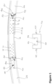
- Figure 1 schematically illustrates two structural parts 51a and 51b that are to be mounted to one another with a coupling 52, using positioning devices 100a and 100b, and a fastening device 400.
- the two structural parts 51a,b can either overlap one another, or are coupled to one another, as illustrated, via a coupling 52, which overlaps a respective area of the structural parts 51a,b.
- a plurality of fastening positions 71 are predefined.
- a fastener 72 is to be placed, such as a rivet, a screw, self-piercing fastener, a bolt or the like.
- Each of the fasteners 72 penetrates the first structural part 51 and the overlapping part 52, in order to bind and fix both parts 51, 52 to one another. This can additionally be supported by (automatically) drilling a through hole at each fastening position 71, or having an "unclosed" rivet already placed at each fastening position 71 that can then be closed to fasten the two structural parts 51a,b to one another.
- the fastening device 400 can be a U-shaped device, such as a clamp, having a fastener placing device 410 at each free end of the U-shaped clamp.
- the fastener placing device 410 can be implemented as a riveting device that provides a rivet or a self-piercing fastener 72 through the two structural parts 51, 52 to be coupled to one another.
- Each free end of the fastening device 400 is to be placed on one of the opposite sides of one of the fastening positions 71 (in Figure 1 only one side is visible).
- the fastener placing device 410 can then operate from both sides of the two structural parts 51, 52.
- the structural parts 51, 52 have to be hold or clamped to one another. Thereafter, a first fastener 72 has to be provided, so that the two parts 51, 52 are fixed. Then further fasteners 72 can be provided at other fastening positions 71.
- a positioning device 100a,b is provided for each pair of structural parts 51, 52.
- Figure 1 illustrates a first positioning device 100a that is mounted to a first structural part 51a, and a second positioning device 100b that is mounted to a second structural part 51b. The details of the positioning devices 100a,b are explained with respect to Figures 3 to 6 .
- Both positioning devices 100a,b are mounted to a predefined position at/on the respective structural part 51a,b. Thus, the location and orientation of both positioning devices 100a,b can be determined, which further allows determining the location and orientation of the respective structural parts 51a,b.
- the positioning devices 100a,b are each provided with a clamp 141 (see Figures 3 to 6 ).
- This clamp 141 can press the coupling 52 onto the respective structural part 51a,b.
- the coupling 52 can be hold and fixed by only one device, i.e. the positioning device 100, before the coupling 52 is fastened to the structural part 51.
- the first positioning device 100a (to the left in Figure 1 ) additionally comprises at least one guidance face 111, 112, 113 (see Figures 3 and 4 ), which allows abutting the coupling 52 against it.
- the coupling 52 can be oriented with respect to the positioning device 100a and, hence, with respect to the structural part 51a.
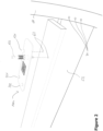
- FIG 2 schematically illustrates two structural parts 51, 53 that are to be mounted to one another, using a positioning device 100c.
- the positioning device 100c is mounted to one of the two structural parts, here a crossbeam 53.
- the details of the positioning device 100c are illustrated in and explained with respect to Figures 7 and 8 .
- Figure 3 schematically illustrates a positioning device 100a relative to a structural part 51.
- Figure 4 schematically illustrates a different perspective of the positioning device 100a.
- the structural part 51 (not illustrated in Figure 4 ) is provided with a pair of fixation holes 63, which can be, for example, through holes.
- fixation holes 63 can be made with high precision, particularly with respect to diameter and relative position to one another as well as relative position to a particular edge, corner and/or side face of the structural part 51.
- the pair of fixation holes 63 allows determining a position and an orientation of the structural part 51 in a three-dimensional space and, hence, the corresponding position and orientation of the edge, corner and/or side face of the structural part 51.
- the positioning device 100a comprises a plate 110 that forms the main body of the positioning device 100.
- the plate 110 has a first side (visible in Figure 4 ) and a second side (visible in Figure 3 ) opposite to the first side.
- a guiding pin 121 is mounted to the plate 110 and extends perpendicularly from the first side of the plate 110.
- the guiding pin 121 has a length L the major part of which extends from the first side.
- the positioning device 100 further comprises an expandable pin 122 mounted to the plate 110 and having an expandable portion 124 that also extends perpendicularly from the first side of the plate 110.
- the relative position of the expandable pin 122 to the guiding pin 121 is predefined and should be made with high precision. Furthermore, the relative position of the expandable pin 122 and the guiding pin 121 corresponds to the relative position of the pair of fixation holes 63 in the structural part 51.
- the guiding pin 121 can be inserted into a first hole of the pair of fixation holes 63, and the expendable pin 122 can be inserted into a second hole of the pair of fixation holes 63 (simultaneously).
- the expendable portion 124 of the expendable pin 122 can be expanded, for example when the expendable portion 124 is arranged inside the associated fixation hole 63 or on the first side of the plate 110.
- the expanding of the expendable portion 124 can be achieved, for example, by rotating an associated mechanic 123, such as a screw or threaded bolt. This task can be performed by a tool (not illustrated) used by a person or robot (not illustrated).
- the expendable portion 124 fixes the plate 110 to a surface of the structural part 51.
- the expendable portion 124 can be configured to pull the plate 110 onto the surface of the structural part 51.
- the positioning device 100 is now mounted to the structural part 51 in a predefined position due to the predefined location of the fixation holes 63 (see Figures 1 and 3 ).
- the positioning device 100a comprises at least two reflectors 131, 132.
- the two reflectors 131, 132 are respectively arranged at opposite ends of the guiding pin 121.
- each reflector 131, 132 is located on opposite sides of the structural part 51.
- the reflector 131 is visible on the side where the positioning device 100a is mounted, while the other reflector 132 is visible on the opposite side.
- a camera 421, 422, 423 can capture an image of the positioning device 100 including the at least two reflectors 131, 132.
- FIG. 1 three optional cameras 421, 422, 423 are illustrated as forming part of the fastening device 400. It is to be understood that this is only one of a plurality of possible arrangements for the camera(s) 421, 422, 423. For instance, one or more of the camera(s) 421, 422, 423 can also be arranged at a robot arm or the like.
- a camera 423 may capture an image from an underside of the structural part 51a (i.e., the camera 423 has a viewing direction from the bottom to the top in Figure 1 ). It is further assumed that the length L of the guiding pin 121 is longer than the thickness of the structural part 51a. In this case, the camera 423 captures the first reflector 131 on a right-hand side of the structural part 51a, and the second reflector 132 on the left-hand side of the structural part 51a.
- the fastening device 400 at one of the fastening positions 71, the position and orientation of the positioning device 100a and, hence, of the structural part 51a, can be determined from the captured image. Therefore, a precise positioning of the fastener placing device 410 with respect to the fastening positions 71 can be achieved.
- the positioning device 100a further comprises an identifier 133, which is located offside of the straight line connecting the two reflectors 131, 132.
- a triangle of predefined positions can be captured by a camera, which facilitates determination of the position and orientation of the positioning device 100a and, hence, of the structural part 51a.
- the identifier 133 may include a machine-readable code, such as a barcode, QR code, unique image, unique colour or the like.
- the identifier 133 may include a reflector, for example, having the same reflecting capabilities as the first and second reflectors 131, 132.
- the positioning device 100a comprises at least one guidance face 111, 112, 113 protruding from the plate 110. Protruding from the plate 110 can mean extending away from the plate 110 at any desired angle, so that the respective guidance face 111, 112, 113 extends away from a plane defined by the plate 110.
- Each guidance face 111, 112, 113 can be positioned on the positioning device 100a, so that it has a particular relative position to the guiding pin 121 and the expendable pin 122, such as a predefined relative position.
- One guidance face 113 can be used as locating the identifier 133. For instance, if the guidance face 113 faces a direction where a camera will capture an image of the first and second reflectors 131, 132, then the identifier 133 is also visible for the camera.
- each guidance face 111, 112, 113 can be arranged and employed to contact or abut against a portion of one or more of the structural parts 51, 52.
- a guidance face 111 may abut against a flange of the structural part 51a.
- Another guidance face 112 may abut against the flange of the structural part 51a and may further abut against a side/front face of the coupling 52.
- another guidance face 113 may abut against the side/front face of the coupling 52 (preferably at a different position than the other guidance face 112).
- the positioning device 100 does not only allow to be mounted to the structural part 51 in a predefined position.
- the positioning device 100 further allows positioning the coupling 52 including transferring any forces from the coupling 52 to the structural part 51 via the guidance faces 111, 112, 113 (as well as the plate 110, the guiding pin 121 and the expendable pin 122).
- the positioning device 100a can be specifically shaped for the coupling 52. Since a plurality of structural parts, for example in a vehicle, can have the same form and shape, the same positioning devices 100 can be used. It is to be understood that the positioning device 100 can have any form and shape, in order to facilitate positioning, orienting and fastening two structural parts 51, 52, 53 to one another.
- the positioning device 100 can include a clamp 141 mounted to the second side of the plate 110.
- the clamp 141 can comprise a slot 143, through which a button 142 runs, to connect the clamp 141 to the plate 110.
- the slot 143 allows a rotational and linear movement of the clamp 141 with respect to the plate 110.
- a free end 145 of the clamp 141 (preferably opposite to the end where the slot 143 is arranged) can be arranged, so that it extends over an edge of the plate 110.
- This free end 145 can be provided in a position overlapping the coupling 52 or another structural part 51, 53.
- the clamping fixture 144 for example, can be a screw or threaded bolt.
- the clamp 141 can fix the coupling 52 or other structural part 51, 53 to the structural part 51a, on which the positioning device 100a is mounted.
- the image of the positioning device 100 including the at least two reflectors 131, 132 and the identifier 133 can be captured, and the fastening device 400 can be arranged relative to an intersection/overlap between the first and second structural parts 51, 52 based on a location of the at least two reflectors 131, 132 and the identifier 133 captured in the image.
- the first and second structural parts 51, 52 can be fastened to one another by the fastening device 400, for example, by placing a plurality of fasteners 72 through the first and second structural parts.
- fasteners 72 can be self-piercing fasteners, rivets, screws or the like.
- the fastening device 400 can be controlled by a robot (robot arm), so that an automated fastening of the structural parts 51, 52 can be implemented.
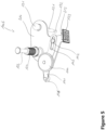
- Figure 5 schematically illustrates another positioning device 100b, such as the positioning device 100b arranged on the right-hand side in Figure 1 .
- the positioning device 100b can be used to position and fix another structural part 51b to the coupling 52.
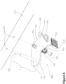
- Figure 6 schematically illustrates a different perspective of the positioning device 100b of Figure 5 and relative to the structural part 51b.
- the positioning device 100b has several portions and components that are (at least functionally) identical to those of the positioning device 100a as explained with respect to Figures 3 and 4 . These portions and components are not explained again, in order to avoid redundant disclosure, and have been referenced by the same numerals.
- the positioning device 100b comprises a plate 210, which is formed smaller than that of positioning device 100a.
- the plate 210 can be formed and shaped with respect to constraints at the second structural part 51b and/or this side of the coupling 52.
- a guiding pin 121 and an expandable pin 122 are part of the positioning device 100b offering the same functions as in Figures 3 and 4 .
- the positioning device 100b can be mounted to the other structural part 51b by inserting the guiding pin 121 and the expendable pin 122 in corresponding fixation holes 63b in the other structural part 51b (see Figure 6 ).
- a clamp 141 is provided.
- the clamp 141 allows holding and fixing the coupling 52 to the other structural part 51b.
- the positioning device 100b comprises a flange or protruding portion 213 carrying the identifier 133.
- the flange or protruding portion 213 can faces a direction where a camera will capture an image of the first and second reflectors 131, 132, so that the identifier 133 is also visible for the camera.
- the image includes four reflectors 131, 132 (two at each positioning device 100a,b) and two identifiers 133 (one at each positioning device 100a,b).
- the pair of fixation holes 63a,b and the location of the guidance faces 112, 113 are predefined, the location and orientation of the coupling 52 can be determined from the captured image.
- the current location of the fastening device 400 (when capturing the image) can be set as a reference point or the fastening device 400 can be brought to a reference point after capturing the image. From there the fastening device 400 can move to each fastening position 71 automatically, i.e., without any readjustment or driving back to the reference point or the like. This allows mounting the fastening device 400 to a robot arm which is controlled based on the captured image information. Thus, a fast fastening of the structural parts 51a,b with the coupling 52 can be achieved and can be fully automated.
- the identifier 133 can further be employed to identify the type of coupling 52 or the pattern of the fastening positions 71, so that the fastening process can be automated, even in case of different patterns of fastening positions 71.
- the camera(s) 421, 422, 423 can capture an image of the positioning devices 100 and determine the position of the structural parts 51, 52, 53 and the fastening positions 71, each time a fastener 72 is placed.
- the camera(s) 421, 422, 423 can capture an image of the positioning devices 100 once before the first fastener 72 is placed, and the position and orientation of the positioning devices 100, and hence the fastening positions 71, is only determined once as a reference point. All fasteners 72 are then placed based on this reference point automatically.
- a crossbeam 53 is to be mounted to a frame 51, both forming structural parts according to the present disclosure. Since the crossbeam 53 is significantly larger (wider) then the structural parts 51 of Figure 1 , the provision of a pair of reflectors on opposite sides may not be possible. Likewise, the area, where the fastening device 400 has to operate when fastening the crossbeam 53 to the frame 51 is much smaller, so that only smaller angles of view for a camera 421, 422, 423 are possible compared to the situation in Figure 1 .
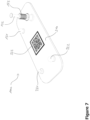
- the positioning device 100c also comprises a guiding pin 321 and an expandable pin 122, which function as already described with respect to Figures 3 to 6 .
- the only difference to guiding pin 321 compared to guiding pin 121 is that it includes only one reflector 131 on the second side of the plate 310 (visible in Figure 7 ).
- the first side of the plate 310 (visible in Figure 8 ) has only the guiding pin 321 and the expendable pin 122 protruding therefrom.
- Figure 8 only illustrates positions of reflectors 331, 332 (the reference numerals have been placed in parentheses).
- the guiding pin 321 and the expendable pin 122 are used to mount the positioning device 100c to the crossbeam 53 by inserting the guiding pin 321 and the expendable pin 122 into the fixation holes 63 in the crossbeam 53 ( Figure 2 ).
- the first side of the plate 310 abuts against a (upper) surface of the crossbeam 53.
- the positioning device 100c comprises three reflectors in total, i.e. reflector 131 on guiding pin 121 as well as reflectors 331 and 332.
- the three reflectors 131, 331 and 332 allow a first determination of a position and orientation of the positioning device 100c.
- two images can be captured by two cameras 422 and 423 arranged at different positions.
- the cameras 422, 423 can be arranged along a line at the fastening device 400. Such line may correspond to a longitudinal axis of the crossbeam 53 or may correspond to a cross-sectional axis of the crossbeam 53.
- two positioning devices 100c could be installed on the crossbeam, or one positioning device 100c is installed on the crossbeam and another positioning device 100 (not illustrated) is installed on the frame 51, in order to increase the number of reflectors to be captured by the cameras 421, 422, 423.
- a solution including only one positioning device 100c requires less fixation holes 63 in the structural parts 51, 53.
- At least one reflector 131, 132, 331, 332 can have a different size than the other reflectors 131, 132, 331, 332.
- reflector 132 in Figures 3 to 6 is smaller (in diameter) than reflector 131. This allows, on the one hand, insertion of the guiding pin 121 into the associated fixation hole 63. On the other hand, it allows determination of the orientation of the positioning device 100a,b,c as the reflectors 131, 132 themselves can be determined by their size.
- reflector 331 is made smaller (in diameter) than the remaining reflectors 131 and 332.
- each of the reflectors 131, 132, 331, 332 can have a unique size and/or form, so that the reflectors 131, 132, 331, 332 can be differentiated from one another. This facilitates determination of the position and orientation of the respective positioning device 100a,b,c.
Landscapes
- Engineering & Computer Science (AREA)
- Mechanical Engineering (AREA)
- General Engineering & Computer Science (AREA)
- Physics & Mathematics (AREA)
- General Physics & Mathematics (AREA)
- Theoretical Computer Science (AREA)
- Automatic Assembly (AREA)
- Connection Of Plates (AREA)
- Automobile Manufacture Line, Endless Track Vehicle, Trailer (AREA)
Abstract
Description
- The present disclosure generally relates to a positioning device and method for mounting two structural parts to one another using such positioning device. Particularly, the present disclosure relates to a positioning device having at least two reflectors and an identifier not located on a common straight line, and a method employing such positioning device when mounting two structural parts to one another.
- When two structural parts are to be mounted to one another, such as two primary structural parts of a vehicle (e.g., an aircraft, a bus, a train, etc.), the two structural parts are placed in the correct (overlapping) position and are temporarily clamped to one another. A fastening device can be moved to a first fastening position, where the fastening device can couple and mount the two structural parts to one another. Subsequently, the fastening device is moved to a second fastening position, and so on until fasteners are placed at all fastening positions.
- A semi-automatic process can be employed, where the moving to the respective fastening position can be performed manually and the placing of the fasteners is performed automatically. Alternatively, a first fastener can be placed manually, in order to fixedly couple both primary structural parts, and the remaining fasteners are placed automatically.
- However, the installation time of such a procedure is quite long. Moreover, if the starting (overlapping) position of the primary structural parts is not correct at the time of placing the first fastener, both parts will be mounted to one another in this incorrect position.
- It is therefore an object of the present disclosure to improve mounting two structural parts to one another, while increasing precision and efficiency of the fastening.
- This object is solved by the present invention as defined in the independent claims. Preferred embodiments are defined by the dependent claims.
- According to a first aspect to better understand the present disclosure, a positioning device comprises a plate forming a main body of the positioning device having a first side and a second side opposite to the first side. The plate, or at least one of the first and second side, can be planar. Alternatively, the plate, or at least one of the first and second side, can be curved. In any case, the plate can be shaped to fit onto a surface of one of the first and second structural parts.
- The positioning device further comprises a guiding pin mounted to the plate and extending perpendicularly from the first side of the plate, and an expendable pin mounted to the plate, wherein an expendable portion of the expendable pin extends perpendicularly from the first side of the plate. Thus, the guiding pin and the expendable pin are provided on the same side of the plate and constitute a guiding and mounting assembly for the positioning device.
- Furthermore, the positioning device comprises at least two reflectors, and an identifier. The at least two reflectors and the identifier are not located on a common straight line. In other words, the at least two reflectors and the identifier can each be arranged at a corner of a polygon. For instance, in case of two reflectors and the identifier, the three items form a triangle. Since the items are not arranged on one straight line, at least a two-dimensional orientation of the positioning device can be determined when looking at the at least two reflectors and the identifier.
- As a mere example, if the positioning device is mounted to a structural part, where the plate touches or abuts against a surface of the structural part, while the guiding pin and the expendable pin penetrate the structural part, the at least two reflectors and the identifier allow determining a spatial position and orientation of the structural part. This can be employed, for example, during fastening the structural part to another component, as the position and orientation of the structural part can be determined.
- In an implementation variant, the at least two reflectors are all arranged on the second side of the plate. This allows detecting all reflectors from one side of the plate, i.e. from one side of the structural part, to which the positioning device can be mounted.
- Alternatively, one reflector of the at least two reflectors is arranged at a free end of the guiding pin arranged on the first side of the plate, and the remaining reflectors of the at least two reflectors are arranged on the second side of the plate. This allows the (first) one reflector on the first side of the plate to be detected on a side of the structural part opposite to a side where the positioning device is mounted. As a mere example, the position and orientation of the positioning device, and hence of the structural part, can be determined when viewing at the structural part and the positioning device from a location close to a plane defined by the plate.
- In another implementation variant, the positioning device can further comprise a clamp mounted to the second side of the plate. Such clamp can be used to hold or fix another structural part to the positioning device and, hence, to the (first) structural part at which the positioning device is mounted. Thus, the positioning device does not only allow determination of the position and orientation of the (first) structural part. The positioning device also allows coupling both structural parts to one another in a predefined position and orientation. For example, both structural parts may be positioned and oriented with respect to one another, so that they can be fastened to one another.
- In yet another implementation variant, the clamp can comprise a free end extending over an edge of the plate. This allows placing the other structural part onto the same side or surface of the (first) structural part, on which the positioning device is mounted. The clamp can then be used to hold and temporarily fix the other structural part, for example, in a position for fastening.
- In a further implementation variant, the clamp can comprise a slot configured to move the clamp rotationally and linearly. This allows positioning the clamp, for example its free end, with respect to the other structural part. The holding capability of the positioning device can, hence, be optimised.
- In an implementation variant, the positioning device can further comprise at least one guidance face protruding from the plate. Such guidance face can protrude from the plate at a position corresponding to a section or portion of the structural device, to which the positioning device can be mounted. The positioning device can therefore be positioned on the structural device in a very precise manner, since more contacting points or areas between the positioning devices and the structural part are provided.
- Alternatively or additionally, the guidance face can protrude from the plate at a position corresponding to a section or portion of another structural device. If the guidance face is in contact with another structural part, the relative position between both structural parts can be more precise, which improves fastening of both structural parts to one another.
- In another implementation variant, the identifier can include a reflecting portion and/or a machine-readable code. The identifier can also be used for determining a position and orientation of the positioning device, since the identifier marks a predefined position on the positioning device. This may be facilitated by the reflecting portion of the identifier. For instance, the reflecting portion may be determined in the same manner as the at least two reflectors, so that all three items look similar.
- The machine-readable code can be any code that allows mapping the code to an unambiguous number or character combination. As mere examples, the machine-readable code can be or include a barcode, QR code, unique image, unique colour or the like. Thus, simultaneously with identifying the at least two reflectors and the identifier, the positioning device can be identified. This further allows identifying a group of positioning devices having all the same identifier, or identifying each individual positioning device out of the group of positioning devices, where each positioning device has its unique identifier. As a mere example, based on the identification the position of fasteners at the structural part(s) can be determined. Thus the positioning device can be matched to the structural parts.
- According to a second aspect to better understand the present disclosure, a method for mounting two structural parts to one another comprises providing a pair of fixation holes into a first structural part, and mounting a positioning device according to the first aspect or one of its variants to the first structural part. The pair of fixation holes are provided at respective predefined positions on the first structural part. For instance, the positions of the fixation holes are predefined, such as relative to an end or edge or the like of the first structural part. Thus, the position of any device mounted to such fixation hole can be determined relative to the shape of the first structural part or any other referenced location on the first structural part.
- The fixation holes can be provided by machining, drilling or eroding the material of the first structural part. Alternatively, the fixation holes may already be provided when manufacturing the first structural part. For example, the first structural part may be moulded. Two protrusions in the mould can then form the pair of fixation holes.
- The positioning device is mounted to the first structural part by inserting the guiding pin into a first hole of the pair of fixation holes, inserting the expendable pin into a second hole of the pair of fixation holes, and expanding the expendable portion of the expendable pin. Thus, the plate of the positioning device is coupled and fixed (mounted) to the first structural part in a predefined position and orientation. The positioning device can, hence, also be referred to as a referencing tool or device. The more precise the fixation holes are made, the more precise is the predefined location and orientation of the positioning device relative to the first structural device.
- The method further comprises positioning a second structural part relative to the first structural part, capturing an image of the positioning device including the at least two reflectors and the identifier, and arranging a fastening device relative to an intersection between the first and second structural parts based on a location of the at least two reflectors and the identifier captured in the image. Since the location of the at least two reflectors and the identifier captured in the image and the location of the pair of fixation holes is known, this altogether identifies the position and orientation of the positioning device. Thus, the position and orientation of the first structural part can be determined based on the location of the at least two reflectors and the identifier captured in the image. Furthermore, the respective shape of the first and second structural parts can also be predefined, so that the fastening device can be precisely arranged (positioned) relative to the first and second structural parts.
- The intersection between the first and second structural parts includes an area, where the first and second structural parts overlap. For instance, the first and second structural parts may each have an area that abuts against each other and forms an area where fastening positions for fasteners can be predefined.
- The method can further comprise fastening the first and second structural parts to one another by the fastening device. The positioning device mounted to the first structural part facilitates a precise arranging and positioning of the fastening device, i.e. facilitates a precise locating of a fastening position at the first and second structural parts.
- Thus, a precise fastening of the first and second structural parts is possible. It is additionally possible to automate this fastening process, as camera images can be evaluated by an automatic fastening device, in order to determine the position and orientation of the positioning device and the structural parts. Thus, once the structural parts are brought into the correct position, an automatic fastening device can operate solely based on images of the reflectors and identifier of the positioning device.
- In an implementation variant, said capturing an image can comprise capturing a first image of the positioning device with a first camera and a second image of the positioning device with a second camera. The position of the first camera and the second camera with respect to one another and/or with respect to the fastening device can be predefined. Thus, the position and orientation of the positioning device and, hence, the first and second structural parts in a three-dimensional space can be determined using triangulation.
- In a further implementation variant, said positioning the second structural part can comprise clamping the second structural part to the first structural part using a clamp of the positioning device. Thus, the positioning device, the position and orientation of which is known or at least determinable, further allows positioning the second structural part relative to the first structural part in a (also determinable) position and orientation.
- In yet a further implementation variant, said mounting the positioning device can comprise inserting the guiding pin through the first hole of the pair of fixation holes to such an extent that a first reflector arranged at one end of the guiding pin and a second reflector arranged at the other end of the guiding pin each extend over a side surface of the first and second structural parts. As a mere example, the first and/or second structural part may have a certain thickness in a direction along which the guiding pin extends. This thickness of the first and/or second structural part is smaller than a length of the guiding pin or a distance between the first and second reflector.
- The fastening device can for example be a fastening clamp (a U-shaped device) that moves over the first and second structural parts, so that the ends of the fastening clamp are arranged at each of the side surfaces of the first and second structural parts. In this position, a camera can capture an image of the first and second reflector respectively arranged on the sides of the ends of the fastening clamp, so that the position and orientation of the positioning device is determinable from the camera perspective.
- In another implementation variant, said fastening the first and second structural parts can comprise placing a plurality of self-piercing fasteners through the first and second structural parts. Such self-piercing fasteners allow a fast fastening of the first and second structural parts, as no through holes have to be formed first.
- Moreover, even if more than two structural parts are fastens to one another, this can be achieved by this method, including self-piercing fasteners.
- In yet another implementation variant, said fastening device can be moved by a robot arm. The robot arm can further be controlled based on an image captured by one or more cameras looking at the positioning device.
- The present disclosure is not restricted to the aspects and variants in the described form and order. Specifically, the description of aspects and variants is not to be understood as a specific limiting grouping of features. It is to be understood that the present disclosure also covers combinations of the aspects and variants. Thus, each variant or optional feature can be combined with any other aspect, variant, optional feature or even combinations thereof.
- In the following, the present disclosure will further be described with reference to exemplary implementations illustrated in the figures, in which:
- Figure 1
- schematically illustrates two structural parts that are to be mounted to one another with a coupling, using positioning devices and a fastening device;
- Figure 2
- schematically illustrates two structural parts that are to be mounted to one another, using a positioning device;
- Figure 3
- schematically illustrates an exemplary positioning device relative to a structural part;
- Figure 4
- schematically illustrates a different perspective of the positioning device of
Figure 3 ; - Figure 5
- schematically illustrates another exemplary positioning device;
- Figure 6
- schematically illustrates a different perspective of the positioning device of
Figure 5 and relative to a structural part; - Figure 7
- schematically illustrates a further exemplary positioning device; and
- Figure 8
- schematically illustrates a different perspective of the positioning device of
Figure 7 . - In the following description, for purposes of explanation and not limitation, specific details are set forth in order to provide a thorough understanding of the present disclosure. It will be apparent to one skilled in the art that the present disclosure may be practiced in other implementations that depart from these specific details.
-
Figure 1 schematically illustrates twostructural parts 51a and 51b that are to be mounted to one another with acoupling 52, usingpositioning devices 100a and 100b, and afastening device 400. The two structural parts 51a,b can either overlap one another, or are coupled to one another, as illustrated, via acoupling 52, which overlaps a respective area of the structural parts 51a,b. In any case, in an overlap area, a plurality offastening positions 71 are predefined. At each of these fastening positions 71 afastener 72 is to be placed, such as a rivet, a screw, self-piercing fastener, a bolt or the like. Each of thefasteners 72 penetrates the firststructural part 51 and the overlappingpart 52, in order to bind and fix bothparts fastening position 71, or having an "unclosed" rivet already placed at eachfastening position 71 that can then be closed to fasten the two structural parts 51a,b to one another. - The
fastening device 400 can be a U-shaped device, such as a clamp, having afastener placing device 410 at each free end of the U-shaped clamp. As a mere example, thefastener placing device 410 can be implemented as a riveting device that provides a rivet or a self-piercingfastener 72 through the twostructural parts fastening device 400 is to be placed on one of the opposite sides of one of the fastening positions 71 (inFigure 1 only one side is visible). Thefastener placing device 410 can then operate from both sides of the twostructural parts - In conventional fastening techniques, the
structural parts first fastener 72 has to be provided, so that the twoparts further fasteners 72 can be provided at other fastening positions 71. - In order to increase efficiency and precision of the fastening of the
structural parts structural parts Figure 1 illustrates a first positioning device 100a that is mounted to a first structural part 51a, and asecond positioning device 100b that is mounted to a secondstructural part 51b. The details of the positioning devices 100a,b are explained with respect toFigures 3 to 6 . - Both positioning devices 100a,b are mounted to a predefined position at/on the respective structural part 51a,b. Thus, the location and orientation of both positioning devices 100a,b can be determined, which further allows determining the location and orientation of the respective structural parts 51a,b.
- Moreover, the positioning devices 100a,b are each provided with a clamp 141 (see
Figures 3 to 6 ). Thisclamp 141 can press thecoupling 52 onto the respective structural part 51a,b. Thus, thecoupling 52 can be hold and fixed by only one device, i.e. thepositioning device 100, before thecoupling 52 is fastened to thestructural part 51. - The first positioning device 100a (to the left in
Figure 1 ) additionally comprises at least oneguidance face 111, 112, 113 (seeFigures 3 and4 ), which allows abutting thecoupling 52 against it. Thus, thecoupling 52 can be oriented with respect to the positioning device 100a and, hence, with respect to the structural part 51a. -
Figure 2 schematically illustrates twostructural parts crossbeam 53. The details of the positioning device 100c are illustrated in and explained with respect toFigures 7 and8 . - As indicated above,
Figure 3 schematically illustrates a positioning device 100a relative to astructural part 51.Figure 4 schematically illustrates a different perspective of the positioning device 100a. The structural part 51 (not illustrated inFigure 4 ) is provided with a pair of fixation holes 63, which can be, for example, through holes. Such fixation holes 63 can be made with high precision, particularly with respect to diameter and relative position to one another as well as relative position to a particular edge, corner and/or side face of thestructural part 51. Thus, the pair of fixation holes 63 allows determining a position and an orientation of thestructural part 51 in a three-dimensional space and, hence, the corresponding position and orientation of the edge, corner and/or side face of thestructural part 51. - The positioning device 100a comprises a plate 110 that forms the main body of the
positioning device 100. The plate 110 has a first side (visible inFigure 4 ) and a second side (visible inFigure 3 ) opposite to the first side. A guidingpin 121 is mounted to the plate 110 and extends perpendicularly from the first side of the plate 110. The guidingpin 121 has a length L the major part of which extends from the first side. - The
positioning device 100 further comprises anexpandable pin 122 mounted to the plate 110 and having anexpandable portion 124 that also extends perpendicularly from the first side of the plate 110. The relative position of theexpandable pin 122 to the guidingpin 121 is predefined and should be made with high precision. Furthermore, the relative position of theexpandable pin 122 and the guidingpin 121 corresponds to the relative position of the pair of fixation holes 63 in thestructural part 51. - Thus, the guiding
pin 121 can be inserted into a first hole of the pair of fixation holes 63, and theexpendable pin 122 can be inserted into a second hole of the pair of fixation holes 63 (simultaneously). Theexpendable portion 124 of theexpendable pin 122 can be expanded, for example when theexpendable portion 124 is arranged inside the associatedfixation hole 63 or on the first side of the plate 110. The expanding of theexpendable portion 124 can be achieved, for example, by rotating an associatedmechanic 123, such as a screw or threaded bolt. This task can be performed by a tool (not illustrated) used by a person or robot (not illustrated). - In any case, the
expendable portion 124 fixes the plate 110 to a surface of thestructural part 51. Theexpendable portion 124 can be configured to pull the plate 110 onto the surface of thestructural part 51. In any case, thepositioning device 100 is now mounted to thestructural part 51 in a predefined position due to the predefined location of the fixation holes 63 (seeFigures 1 and3 ). - Furthermore, the positioning device 100a comprises at least two
reflectors reflectors pin 121. Thus, when the positioning device 100a is mounted to thestructural part 51, eachreflector structural part 51. With reference toFigure 1 , thereflector 131 is visible on the side where the positioning device 100a is mounted, while theother reflector 132 is visible on the opposite side. For instance, acamera positioning device 100 including the at least tworeflectors - In
Figure 1 threeoptional cameras fastening device 400. It is to be understood that this is only one of a plurality of possible arrangements for the camera(s) 421, 422, 423. For instance, one or more of the camera(s) 421, 422, 423 can also be arranged at a robot arm or the like. - According to a further example, a
camera 423 may capture an image from an underside of the structural part 51a (i.e., thecamera 423 has a viewing direction from the bottom to the top inFigure 1 ). It is further assumed that the length L of the guidingpin 121 is longer than the thickness of the structural part 51a. In this case, thecamera 423 captures thefirst reflector 131 on a right-hand side of the structural part 51a, and thesecond reflector 132 on the left-hand side of the structural part 51a. Thus, when arranging thefastening device 400 at one of the fastening positions 71, the position and orientation of the positioning device 100a and, hence, of the structural part 51a, can be determined from the captured image. Therefore, a precise positioning of thefastener placing device 410 with respect to the fastening positions 71 can be achieved. - The positioning device 100a further comprises an
identifier 133, which is located offside of the straight line connecting the tworeflectors identifier 133 may include a machine-readable code, such as a barcode, QR code, unique image, unique colour or the like. Alternatively or additionally, theidentifier 133 may include a reflector, for example, having the same reflecting capabilities as the first andsecond reflectors - Furthermore, the positioning device 100a comprises at least one
guidance face 111, 112, 113 protruding from the plate 110. Protruding from the plate 110 can mean extending away from the plate 110 at any desired angle, so that therespective guidance face 111, 112, 113 extends away from a plane defined by the plate 110. Eachguidance face 111, 112, 113 can be positioned on the positioning device 100a, so that it has a particular relative position to the guidingpin 121 and theexpendable pin 122, such as a predefined relative position. - One guidance face 113 can be used as locating the
identifier 133. For instance, if the guidance face 113 faces a direction where a camera will capture an image of the first andsecond reflectors identifier 133 is also visible for the camera. - Furthermore, each
guidance face 111, 112, 113 can be arranged and employed to contact or abut against a portion of one or more of thestructural parts Figure 1 , a guidance face 111 may abut against a flange of the structural part 51a. Anotherguidance face 112 may abut against the flange of the structural part 51a and may further abut against a side/front face of thecoupling 52. Likewise, another guidance face 113 may abut against the side/front face of the coupling 52 (preferably at a different position than the other guidance face 112). - Thus, the
positioning device 100 does not only allow to be mounted to thestructural part 51 in a predefined position. Thepositioning device 100 further allows positioning thecoupling 52 including transferring any forces from thecoupling 52 to thestructural part 51 via the guidance faces 111, 112, 113 (as well as the plate 110, the guidingpin 121 and the expendable pin 122). - The positioning device 100a can be specifically shaped for the
coupling 52. Since a plurality of structural parts, for example in a vehicle, can have the same form and shape, thesame positioning devices 100 can be used. It is to be understood that thepositioning device 100 can have any form and shape, in order to facilitate positioning, orienting and fastening twostructural parts - Moreover, the
positioning device 100 can include aclamp 141 mounted to the second side of the plate 110. Theclamp 141 can comprise aslot 143, through which abutton 142 runs, to connect theclamp 141 to the plate 110. Theslot 143 allows a rotational and linear movement of theclamp 141 with respect to the plate 110. Afree end 145 of the clamp 141 (preferably opposite to the end where theslot 143 is arranged) can be arranged, so that it extends over an edge of the plate 110. Thisfree end 145 can be provided in a position overlapping thecoupling 52 or anotherstructural part clamping fixture 144, thefree end 145 can be pressed onto thecoupling 52 or otherstructural part clamping fixture 144, for example, can be a screw or threaded bolt. Thus, theclamp 141 can fix thecoupling 52 or otherstructural part - When the first and second
structural parts positioning device 100 including the at least tworeflectors identifier 133 can be captured, and thefastening device 400 can be arranged relative to an intersection/overlap between the first and secondstructural parts reflectors identifier 133 captured in the image. Then the first and secondstructural parts fastening device 400, for example, by placing a plurality offasteners 72 through the first and second structural parts.Such fasteners 72 can be self-piercing fasteners, rivets, screws or the like. Thefastening device 400 can be controlled by a robot (robot arm), so that an automated fastening of thestructural parts -
Figure 5 schematically illustrates anotherpositioning device 100b, such as thepositioning device 100b arranged on the right-hand side inFigure 1 . Thepositioning device 100b can be used to position and fix anotherstructural part 51b to thecoupling 52.Figure 6 schematically illustrates a different perspective of thepositioning device 100b ofFigure 5 and relative to thestructural part 51b. Thepositioning device 100b has several portions and components that are (at least functionally) identical to those of the positioning device 100a as explained with respect toFigures 3 and4 . These portions and components are not explained again, in order to avoid redundant disclosure, and have been referenced by the same numerals. - The
positioning device 100b comprises a plate 210, which is formed smaller than that of positioning device 100a. For instance, the plate 210 can be formed and shaped with respect to constraints at the secondstructural part 51b and/or this side of thecoupling 52. Nevertheless, a guidingpin 121 and anexpandable pin 122 are part of thepositioning device 100b offering the same functions as inFigures 3 and4 . Thus, thepositioning device 100b can be mounted to the otherstructural part 51b by inserting the guidingpin 121 and theexpendable pin 122 in corresponding fixation holes 63b in the otherstructural part 51b (seeFigure 6 ). - Likewise, a
clamp 141 is provided. Theclamp 141 allows holding and fixing thecoupling 52 to the otherstructural part 51b. Moreover, thepositioning device 100b comprises a flange or protrudingportion 213 carrying theidentifier 133. - Thus, the flange or protruding
portion 213 can faces a direction where a camera will capture an image of the first andsecond reflectors identifier 133 is also visible for the camera. - It is to be understood that the other
structural part 51b can likewise be coupled and fixed to thecoupling 52 with a positioning device 100a as it is illustrated inFigures 3 and4 but with a mirror-inverted setup. - In any case, when a
camera coupling 52 as well as both positioning devices 100a,b, the image includes fourreflectors 131, 132 (two at each positioning device 100a,b) and two identifiers 133 (one at each positioning device 100a,b). Thus, a precise determination of the location and orientation of the two structural parts 51a,b and thecoupling 52 is possible as six points in a three-dimensional space can be captured. As the pairs of fixation holes 63a,b and the location of the guidance faces 112, 113 are predefined, the location and orientation of thecoupling 52 can be determined from the captured image. - Thus, the current location of the fastening device 400 (when capturing the image) can be set as a reference point or the
fastening device 400 can be brought to a reference point after capturing the image. From there thefastening device 400 can move to eachfastening position 71 automatically, i.e., without any readjustment or driving back to the reference point or the like. This allows mounting thefastening device 400 to a robot arm which is controlled based on the captured image information. Thus, a fast fastening of the structural parts 51a,b with thecoupling 52 can be achieved and can be fully automated. Theidentifier 133 can further be employed to identify the type ofcoupling 52 or the pattern of the fastening positions 71, so that the fastening process can be automated, even in case of different patterns of fastening positions 71. - As a mere example, the camera(s) 421, 422, 423 can capture an image of the
positioning devices 100 and determine the position of thestructural parts fastener 72 is placed. Alternatively, the camera(s) 421, 422, 423 can capture an image of thepositioning devices 100 once before thefirst fastener 72 is placed, and the position and orientation of thepositioning devices 100, and hence the fastening positions 71, is only determined once as a reference point. Allfasteners 72 are then placed based on this reference point automatically. - Turning to
Figure 2 and the details of the positioning device 100c inFigures 7 and8 . Specifically, acrossbeam 53 is to be mounted to aframe 51, both forming structural parts according to the present disclosure. Since thecrossbeam 53 is significantly larger (wider) then thestructural parts 51 ofFigure 1 , the provision of a pair of reflectors on opposite sides may not be possible. Likewise, the area, where thefastening device 400 has to operate when fastening thecrossbeam 53 to theframe 51 is much smaller, so that only smaller angles of view for acamera Figure 1 . - Thus, the
crossbeam 53 is provided with a pair of fixation holes 63 in the same manner as described with respect toFigures 1 and3 to 6 . The positioning device 100c also comprises a guidingpin 321 and anexpandable pin 122, which function as already described with respect toFigures 3 to 6 . The only difference to guidingpin 321 compared to guidingpin 121 is that it includes only onereflector 131 on the second side of the plate 310 (visible inFigure 7 ). Actually, the first side of the plate 310 (visible inFigure 8 ) has only the guidingpin 321 and theexpendable pin 122 protruding therefrom. Thus,Figure 8 only illustrates positions ofreflectors 331, 332 (the reference numerals have been placed in parentheses). - The guiding
pin 321 and theexpendable pin 122 are used to mount the positioning device 100c to thecrossbeam 53 by inserting the guidingpin 321 and theexpendable pin 122 into the fixation holes 63 in the crossbeam 53 (Figure 2 ). Thus, the first side of theplate 310 abuts against a (upper) surface of thecrossbeam 53. - The positioning device 100c comprises three reflectors in total, i.e. reflector 131 on guiding
pin 121 as well asreflectors reflectors crossbeam 53 and likewise the intersection/overlap betweencrossbeam 53 andframe 51, two images can be captured by twocameras cameras fastening device 400. Such line may correspond to a longitudinal axis of thecrossbeam 53 or may correspond to a cross-sectional axis of thecrossbeam 53. - It is to be understood that two positioning devices 100c could be installed on the crossbeam, or one positioning device 100c is installed on the crossbeam and another positioning device 100 (not illustrated) is installed on the
frame 51, in order to increase the number of reflectors to be captured by thecameras structural parts - With reference to all positioning devices 100a,b,c it is to be noted that at least one
reflector other reflectors reflector 132 inFigures 3 to 6 is smaller (in diameter) thanreflector 131. This allows, on the one hand, insertion of the guidingpin 121 into the associatedfixation hole 63. On the other hand, it allows determination of the orientation of the positioning device 100a,b,c as thereflectors Figures 7 and8 ,reflector 331 is made smaller (in diameter) than the remainingreflectors - It is further to be understood that in case of three reflectors or more, each of the
reflectors reflectors
Claims (12)
- A positioning device (100), comprising:a plate (110, 210, 310) forming a main body of the positioning device (100) having a first side and a second side opposite to the first side;a guiding pin (121, 321) mounted to the plate (110, 210, 310) and extending perpendicularly from the first side of the plate (110, 210, 310);an expendable pin (122) mounted to the plate (110, 210, 310), wherein an expendable portion (124) of the expendable pin (122) extends perpendicularly from the first side of the plate (110, 210, 310);at least two reflectors (131, 132, 331, 332); andan identifier (133, 333),wherein the at least two reflectors (131, 132, 331, 332) and the identifier (133, 333) are not located on a common straight line.
- The device according to claim 1, wherein the at least two reflectors (131, 132, 331, 332) are all arranged on the second side of the plate (110, 210, 310), or
wherein one reflector (132) of the at least two reflectors (131, 132, 331, 332) is arranged at a free end of the guiding pin (121) arranged on the first side of the plate (110, 210, 310), and the remaining reflectors (131, 331, 332) of the at least two reflectors (131, 132, 331, 332) are arranged on the second side of the plate(110, 210, 310). - The device according to claim 1 or 2, further comprising:
a clamp (141) mounted to the second side of the plate (110, 210, 310). - The device according to claim 3, wherein the clamp (141) comprises a free end (145) extending over an edge of the plate (110, 210, 310).
- The device according to claim 3 or 4, wherein the clamp (141) comprises a slot (143) configured to move the clamp (141) rotationally and linearly.
- The device according to one of claims 1 to 5, further comprising:
at least one guidance face (111, 112, 113) protruding from the plate (110, 210, 310). - The device according to one of claims 1 to 6, wherein the identifier (133, 333) includes a machine-readable code and/or a reflecting portion.
- A method for mounting two structural parts to one another, the method comprising:providing (505) a pair of fixation holes into a first structural part (51, 53);mounting (510) a positioning device (100) according to one of claims 1 to 7 to the first structural part (51, 53) by inserting the guiding pin (121, 321) into a first hole of the pair of fixation holes, inserting the expendable pin (122) into a second hole of the pair of fixation holes, and expanding the expendable portion (124) of the expendable pin (122);positioning (520) a second structural part relative to the first structural part;capturing (530) an image of the positioning device (100) including the at least two reflectors (131, 132, 331, 332) and the identifier (133, 333);arranging (540) a fastening device (400) relative to an intersection between the first and second structural parts based on a location of the at least two reflectors (131, 132, 331, 332) and the identifier (133, 333) captured in the image; andfastening (545) the first and second structural parts to one another by the fastening device (400).
- The method according to claim 8, wherein capturing (530) an image comprises capturing a first image of the positioning device (100) with a first camera (421) and a second image of the positioning device (100) with a second camera (422).
- The method according to claim 8 or 9, wherein positioning (520) the second structural part comprises clamping (525) the second structural part to the first structural part using a clamp (141) of the positioning device (100).
- The method according to one of claims 8 to 10, wherein mounting (510) the positioning device (100) comprises inserting the guiding pin (121) through the first hole of the pair of fixation holes to such an extent that a first reflector (131) arranged at one end of the guiding pin (121) and a second reflector (132) arranged at the other end of the guiding pin (121) each extend over a side surface of the first and second structural parts.
- The method according to one of claims 8 to 11, wherein fastening (545) the first and second structural parts comprises placing a plurality of self-piercing fasteners through the first and second structural parts.
Priority Applications (4)
| Application Number | Priority Date | Filing Date | Title |
|---|---|---|---|
| EP23162261.4A EP4431402B1 (en) | 2023-03-16 | 2023-03-16 | Positioning and referencing device for clamping parts |
| ES23162261T ES3059434T3 (en) | 2023-03-16 | 2023-03-16 | Positioning and referencing device for clamping parts |
| CN202410174465.2A CN118664528A (en) | 2023-03-16 | 2024-02-07 | Positioning device and method for mounting two structural components to each other |
| US18/594,449 US20240307951A1 (en) | 2023-03-16 | 2024-03-04 | Positioning and referencing device for clamping parts |
Applications Claiming Priority (1)
| Application Number | Priority Date | Filing Date | Title |
|---|---|---|---|
| EP23162261.4A EP4431402B1 (en) | 2023-03-16 | 2023-03-16 | Positioning and referencing device for clamping parts |
Publications (2)
| Publication Number | Publication Date |
|---|---|
| EP4431402A1 true EP4431402A1 (en) | 2024-09-18 |
| EP4431402B1 EP4431402B1 (en) | 2025-10-29 |
Family
ID=85724502
Family Applications (1)
| Application Number | Title | Priority Date | Filing Date |
|---|---|---|---|
| EP23162261.4A Active EP4431402B1 (en) | 2023-03-16 | 2023-03-16 | Positioning and referencing device for clamping parts |
Country Status (4)
| Country | Link |
|---|---|
| US (1) | US20240307951A1 (en) |
| EP (1) | EP4431402B1 (en) |
| CN (1) | CN118664528A (en) |
| ES (1) | ES3059434T3 (en) |
Citations (4)
| Publication number | Priority date | Publication date | Assignee | Title |
|---|---|---|---|---|
| US4945488A (en) * | 1987-04-14 | 1990-07-31 | Northrop Corporation | Integrated aircraft manufacturing system |
| US6230382B1 (en) * | 1998-05-11 | 2001-05-15 | Vought Aircraft Industries, Inc. | System and method for assembling an aircraft |
| EP2698596A1 (en) * | 2012-08-16 | 2014-02-19 | Hexagon Technology Center GmbH | Method and system for determining spatial coordinates with a mobile coordinate measuring machine |
| DE102020122565B3 (en) * | 2020-08-28 | 2022-01-27 | Beissbarth Gmbh | Measuring panel for vehicle measurement and device and method for optical measurement or calibration of a vehicle component |
Family Cites Families (1)
| Publication number | Priority date | Publication date | Assignee | Title |
|---|---|---|---|---|
| GB2594503A (en) * | 2020-04-30 | 2021-11-03 | Airbus Operations Ltd | Automated clamp |
-
2023
- 2023-03-16 EP EP23162261.4A patent/EP4431402B1/en active Active
- 2023-03-16 ES ES23162261T patent/ES3059434T3/en active Active
-
2024
- 2024-02-07 CN CN202410174465.2A patent/CN118664528A/en active Pending
- 2024-03-04 US US18/594,449 patent/US20240307951A1/en active Pending
Patent Citations (4)
| Publication number | Priority date | Publication date | Assignee | Title |
|---|---|---|---|---|
| US4945488A (en) * | 1987-04-14 | 1990-07-31 | Northrop Corporation | Integrated aircraft manufacturing system |
| US6230382B1 (en) * | 1998-05-11 | 2001-05-15 | Vought Aircraft Industries, Inc. | System and method for assembling an aircraft |
| EP2698596A1 (en) * | 2012-08-16 | 2014-02-19 | Hexagon Technology Center GmbH | Method and system for determining spatial coordinates with a mobile coordinate measuring machine |
| DE102020122565B3 (en) * | 2020-08-28 | 2022-01-27 | Beissbarth Gmbh | Measuring panel for vehicle measurement and device and method for optical measurement or calibration of a vehicle component |
Also Published As
| Publication number | Publication date |
|---|---|
| CN118664528A (en) | 2024-09-20 |
| EP4431402B1 (en) | 2025-10-29 |
| ES3059434T3 (en) | 2026-03-20 |
| US20240307951A1 (en) | 2024-09-19 |
Similar Documents
| Publication | Publication Date | Title |
|---|---|---|
| US9156510B2 (en) | Clamp mounting system | |
| CA2250601C (en) | Laser jigging system for assembly of trusses and method of use | |
| EP0134045B1 (en) | Improved sensing and welding arrangements for manipulator welding apparatus | |
| US9597755B2 (en) | Method for connecting components | |
| US10799937B2 (en) | Component mounting system and component mounting method | |
| JP6523693B2 (en) | Aircraft component positioning device, aircraft assembly system and aircraft assembly method | |
| CN107344222B (en) | A kind of numerical control rivet driver | |
| EP3288711B1 (en) | Inspection of drilled features in objects | |
| US20240307951A1 (en) | Positioning and referencing device for clamping parts | |
| US20190193799A1 (en) | Device and method for joining a lens to a housing of a lighting device of a motor vehicle | |
| CN221475198U (en) | Wire harness assembly fixture | |
| JP2007083391A (en) | Clamp device with clamp holder | |
| CN215066097U (en) | Visual positioning mechanism and visual positioning device with same | |
| US4824087A (en) | Clamp | |
| JPH10329072A (en) | Automatic assembly method for multiple members | |
| EP4448390B1 (en) | An interface node for a robotic arm | |
| TW506240B (en) | Method and apparatus for locating and securing a printed wire board on a screen printer | |
| CN119871062B (en) | A robot for automobile parts | |
| CN116203455B (en) | Self-adaptive high beam locking and electric detecting device | |
| CN216912993U (en) | Clamping device | |
| RU2049647C1 (en) | Divider for feeding parts to drilling zone | |
| EP4197917A1 (en) | An interface node for a robotic arm | |
| CN108907553A (en) | A kind of pressure sensor tube socket clamping tooling and its application method | |
| CN118025378A (en) | Assembly method and assembly tool for vehicle radar | |
| JPH0237453Y2 (en) |
Legal Events
| Date | Code | Title | Description |
|---|---|---|---|
| PUAI | Public reference made under article 153(3) epc to a published international application that has entered the european phase |
Free format text: ORIGINAL CODE: 0009012 |
|
| STAA | Information on the status of an ep patent application or granted ep patent |
Free format text: STATUS: THE APPLICATION HAS BEEN PUBLISHED |
|
| AK | Designated contracting states |
Kind code of ref document: A1 Designated state(s): AL AT BE BG CH CY CZ DE DK EE ES FI FR GB GR HR HU IE IS IT LI LT LU LV MC ME MK MT NL NO PL PT RO RS SE SI SK SM TR |
|
| STAA | Information on the status of an ep patent application or granted ep patent |
Free format text: STATUS: REQUEST FOR EXAMINATION WAS MADE |
|
| 17P | Request for examination filed |
Effective date: 20250318 |
|
| GRAP | Despatch of communication of intention to grant a patent |
Free format text: ORIGINAL CODE: EPIDOSNIGR1 |
|
| STAA | Information on the status of an ep patent application or granted ep patent |
Free format text: STATUS: GRANT OF PATENT IS INTENDED |
|
| RIC1 | Information provided on ipc code assigned before grant |
Ipc: F16B 5/04 20060101ALI20250515BHEP Ipc: F16B 5/02 20060101ALI20250515BHEP Ipc: F16B 19/10 20060101ALI20250515BHEP Ipc: F16B 19/02 20060101ALI20250515BHEP Ipc: F16B 7/04 20060101ALI20250515BHEP Ipc: B64F 5/10 20170101AFI20250515BHEP |
|
| INTG | Intention to grant announced |
Effective date: 20250616 |
|
| GRAS | Grant fee paid |
Free format text: ORIGINAL CODE: EPIDOSNIGR3 |
|
| GRAA | (expected) grant |
Free format text: ORIGINAL CODE: 0009210 |
|
| STAA | Information on the status of an ep patent application or granted ep patent |
Free format text: STATUS: THE PATENT HAS BEEN GRANTED |
|
| AK | Designated contracting states |
Kind code of ref document: B1 Designated state(s): AL AT BE BG CH CY CZ DE DK EE ES FI FR GB GR HR HU IE IS IT LI LT LU LV MC ME MK MT NL NO PL PT RO RS SE SI SK SM TR |
|
| REG | Reference to a national code |
Ref country code: CH Ref legal event code: F10 Free format text: ST27 STATUS EVENT CODE: U-0-0-F10-F00 (AS PROVIDED BY THE NATIONAL OFFICE) Effective date: 20251029 Ref country code: GB Ref legal event code: FG4D |
|
| REG | Reference to a national code |
Ref country code: IE Ref legal event code: FG4D |
|
| REG | Reference to a national code |
Ref country code: DE Ref legal event code: R096 Ref document number: 602023007882 Country of ref document: DE |
|
| REG | Reference to a national code |
Ref country code: NL Ref legal event code: MP Effective date: 20251029 |
|
| REG | Reference to a national code |
Ref country code: ES Ref legal event code: FG2A Ref document number: 3059434 Country of ref document: ES Kind code of ref document: T3 Effective date: 20260320 |
|
| REG | Reference to a national code |
Ref country code: LT Ref legal event code: MG9D |
|
| PG25 | Lapsed in a contracting state [announced via postgrant information from national office to epo] |
Ref country code: NO Free format text: LAPSE BECAUSE OF FAILURE TO SUBMIT A TRANSLATION OF THE DESCRIPTION OR TO PAY THE FEE WITHIN THE PRESCRIBED TIME-LIMIT Effective date: 20260129 |
|
| PGFP | Annual fee paid to national office [announced via postgrant information from national office to epo] |
Ref country code: DE Payment date: 20260319 Year of fee payment: 4 |
|
| PG25 | Lapsed in a contracting state [announced via postgrant information from national office to epo] |
Ref country code: AT Free format text: LAPSE BECAUSE OF FAILURE TO SUBMIT A TRANSLATION OF THE DESCRIPTION OR TO PAY THE FEE WITHIN THE PRESCRIBED TIME-LIMIT Effective date: 20251029 Ref country code: HR Free format text: LAPSE BECAUSE OF FAILURE TO SUBMIT A TRANSLATION OF THE DESCRIPTION OR TO PAY THE FEE WITHIN THE PRESCRIBED TIME-LIMIT Effective date: 20251029 Ref country code: FI Free format text: LAPSE BECAUSE OF FAILURE TO SUBMIT A TRANSLATION OF THE DESCRIPTION OR TO PAY THE FEE WITHIN THE PRESCRIBED TIME-LIMIT Effective date: 20251029 |
|
| PGFP | Annual fee paid to national office [announced via postgrant information from national office to epo] |
Ref country code: AT Payment date: 20260301 Year of fee payment: 4 |
|
| REG | Reference to a national code |
Ref country code: AT Ref legal event code: MK05 Ref document number: 1851345 Country of ref document: AT Kind code of ref document: T Effective date: 20251029 |
|
| PG25 | Lapsed in a contracting state [announced via postgrant information from national office to epo] |
Ref country code: NL Free format text: LAPSE BECAUSE OF FAILURE TO SUBMIT A TRANSLATION OF THE DESCRIPTION OR TO PAY THE FEE WITHIN THE PRESCRIBED TIME-LIMIT Effective date: 20251029 |
|
| PG25 | Lapsed in a contracting state [announced via postgrant information from national office to epo] |
Ref country code: RS Free format text: LAPSE BECAUSE OF FAILURE TO SUBMIT A TRANSLATION OF THE DESCRIPTION OR TO PAY THE FEE WITHIN THE PRESCRIBED TIME-LIMIT Effective date: 20260129 |
|
| PG25 | Lapsed in a contracting state [announced via postgrant information from national office to epo] |
Ref country code: IS Free format text: LAPSE BECAUSE OF FAILURE TO SUBMIT A TRANSLATION OF THE DESCRIPTION OR TO PAY THE FEE WITHIN THE PRESCRIBED TIME-LIMIT Effective date: 20260228 |
|
| PGFP | Annual fee paid to national office [announced via postgrant information from national office to epo] |
Ref country code: FR Payment date: 20260323 Year of fee payment: 4 |
|
| PG25 | Lapsed in a contracting state [announced via postgrant information from national office to epo] |
Ref country code: PT Free format text: LAPSE BECAUSE OF FAILURE TO SUBMIT A TRANSLATION OF THE DESCRIPTION OR TO PAY THE FEE WITHIN THE PRESCRIBED TIME-LIMIT Effective date: 20260302 |
|
| PG25 | Lapsed in a contracting state [announced via postgrant information from national office to epo] |
Ref country code: PL Free format text: LAPSE BECAUSE OF FAILURE TO SUBMIT A TRANSLATION OF THE DESCRIPTION OR TO PAY THE FEE WITHIN THE PRESCRIBED TIME-LIMIT Effective date: 20251029 |
|
| PG25 | Lapsed in a contracting state [announced via postgrant information from national office to epo] |
Ref country code: LV Free format text: LAPSE BECAUSE OF FAILURE TO SUBMIT A TRANSLATION OF THE DESCRIPTION OR TO PAY THE FEE WITHIN THE PRESCRIBED TIME-LIMIT Effective date: 20251029 |
|
| PG25 | Lapsed in a contracting state [announced via postgrant information from national office to epo] |
Ref country code: BG Free format text: LAPSE BECAUSE OF FAILURE TO SUBMIT A TRANSLATION OF THE DESCRIPTION OR TO PAY THE FEE WITHIN THE PRESCRIBED TIME-LIMIT Effective date: 20251029 |