EP4431375A1 - Car provided with a pneumatic unit operated by a gearbox - Google Patents
Car provided with a pneumatic unit operated by a gearbox Download PDFInfo
- Publication number
- EP4431375A1 EP4431375A1 EP24160671.4A EP24160671A EP4431375A1 EP 4431375 A1 EP4431375 A1 EP 4431375A1 EP 24160671 A EP24160671 A EP 24160671A EP 4431375 A1 EP4431375 A1 EP 4431375A1
- Authority
- EP
- European Patent Office
- Prior art keywords
- pneumatic
- car
- gearbox
- shaft
- air flow
- Prior art date
- Legal status (The legal status is an assumption and is not a legal conclusion. Google has not performed a legal analysis and makes no representation as to the accuracy of the status listed.)
- Pending
Links
Images



Classifications
-
- B—PERFORMING OPERATIONS; TRANSPORTING
- B60—VEHICLES IN GENERAL
- B60K—ARRANGEMENT OR MOUNTING OF PROPULSION UNITS OR OF TRANSMISSIONS IN VEHICLES; ARRANGEMENT OR MOUNTING OF PLURAL DIVERSE PRIME-MOVERS IN VEHICLES; AUXILIARY DRIVES FOR VEHICLES; INSTRUMENTATION OR DASHBOARDS FOR VEHICLES; ARRANGEMENTS IN CONNECTION WITH COOLING, AIR INTAKE, GAS EXHAUST OR FUEL SUPPLY OF PROPULSION UNITS IN VEHICLES
- B60K17/00—Arrangement or mounting of transmissions in vehicles
- B60K17/04—Arrangement or mounting of transmissions in vehicles characterised by arrangement, location or kind of gearing
- B60K17/06—Arrangement or mounting of transmissions in vehicles characterised by arrangement, location or kind of gearing of change-speed gearing
-
- B—PERFORMING OPERATIONS; TRANSPORTING
- B62—LAND VEHICLES FOR TRAVELLING OTHERWISE THAN ON RAILS
- B62D—MOTOR VEHICLES; TRAILERS
- B62D35/00—Vehicle bodies characterised by streamlining
-
- B—PERFORMING OPERATIONS; TRANSPORTING
- B62—LAND VEHICLES FOR TRAVELLING OTHERWISE THAN ON RAILS
- B62D—MOTOR VEHICLES; TRAILERS
- B62D37/00—Stabilising vehicle bodies without controlling suspension arrangements
- B62D37/02—Stabilising vehicle bodies without controlling suspension arrangements by aerodynamic means
-
- B—PERFORMING OPERATIONS; TRANSPORTING
- B62—LAND VEHICLES FOR TRAVELLING OTHERWISE THAN ON RAILS
- B62D—MOTOR VEHICLES; TRAILERS
- B62D35/00—Vehicle bodies characterised by streamlining
- B62D35/02—Streamlining the undersurfaces
Definitions
- the present invention relates to a car.
- the present invention relates to a car of the type comprising a support frame defining part of a lower floor of the car; a passenger compartment mounted on the support frame and projecting upwards from the lower floor; an engine to move the car; and an aerodynamic bottom fixed to the support frame and defining part of the lower floor.
- the aerodynamic bottom comprises a front bottom mounted in the area of a front zone of the car, a rear bottom mounted in the area of a rear zone of the car, and a central bottom mounted in the area of a central zone of the car.
- the rear bottom comprises a box-shaped body, defining a pneumatic chamber, and is bounded by a lower wall facing a road surface and provided with a plurality of openings to connect the pneumatic chamber to the outside.
- the pneumatic chamber defines part of a pneumatic unit configured to blow a first air flow out of the pneumatic chamber through the above-mentioned openings and in the direction of the road surface and/or to suck part of a second air flow flowing under the lower floor into the pneumatic chamber through the above-mentioned openings during the normal operation of the car.
- the pneumatic unit further comprises a pneumatic device, which may alternatively be a reversible pneumatic device configured both to blow the first air flow in the direction of the road surface and to suck part of the second air flow, or a pneumatic compressor device to blow the first air flow in the direction of the road surface or a pneumatic suction device to suck part of the second air flow.
- a pneumatic device which may alternatively be a reversible pneumatic device configured both to blow the first air flow in the direction of the road surface and to suck part of the second air flow, or a pneumatic compressor device to blow the first air flow in the direction of the road surface or a pneumatic suction device to suck part of the second air flow.
- known cars of the type described above have some drawbacks mainly due to the fact that the pneumatic unit is relatively complex and expensive, and the car has relatively high weight and big overall dimensions.
- the object of the present invention is to provide a car, which is free of the above-mentioned drawbacks and simple and inexpensive to manufacture.
- number 1 indicates, as a whole, a car, in particular a sports car, comprising a support frame 2 defining part of a lower floor 3 of the car 1.
- the car 1 also comprises a passenger compartment 4 mounted on the frame 2 and projecting upwards from the floor 3, and an aerodynamic bottom 5 fixed to the frame 2 and defining part of the floor 3.
- the bottom 5 comprises a front bottom 6 fixed to the frame 2 in the area of a front zone 7 of the car 1, a rear bottom 8 fixed to the frame 2 in the area of a rear zone 9 of the car 1, and an elongated central bottom 10 fixed to the frame 2 between the bottoms 6 and 8 in the area of a central zone 11 of the car 1.
- the car 1 further comprises an engine 12 of a known type, which is mounted in the centre of the rear zone 9 and is connected to two rear drive wheels 13 of the car 1 via the interposition of a gearbox 14 of a known type.
- the car 1 is also provided with at least one clutch 15 of a known type to connect a drive shaft (not shown) of the engine 12 and an input shaft (not shown) of the gearbox 14 to one another in a releasable manner.
- the rear bottom 8 comprises a front plate 16 and a rear box-shaped body 17 arranged in succession along the rear zone 9 of the car 1.
- the body 17 is bounded by a lower wall 18 facing a road surface (not shown) and defines a pneumatic chamber 19, which communicates with the outside through a plurality of openings 20 obtained through the wall 18.
- the chamber 19 defines part of a pneumatic unit 21 comprising also, in this case, a compressor device 22, which is mounted on the body 17, is provided with an air vent 23 communicating with the outside, and is pneumatically connected to the chamber 19.
- a pneumatic unit 21 comprising also, in this case, a compressor device 22, which is mounted on the body 17, is provided with an air vent 23 communicating with the outside, and is pneumatically connected to the chamber 19.
- the compressor device 22 is operated to blow an air flow F1 out of the chamber 19 through the openings 20 and in the direction of the road surface (not shown) to selectively control the aerodynamic set-up of the car 1 according to an operating parameter, e.g. the speed, of the car 1 and/or a geometric parameter of a driving path (not shown) of the car 1.
- an operating parameter e.g. the speed, of the car 1 and/or a geometric parameter of a driving path (not shown) of the car 1.
- the device 22 has a transmission shaft 24 connected to the aforementioned input shaft (not shown) or to an output shaft 25 of the gearbox 14 via the interposition of a train 26 of gears 27, one of which is splined on the input shaft (not shown) or on the output shaft 25 of the gearbox 14 and the other is connected in a releasable manner to the shaft 24 via the interposition of a clutch 28.
- the compressor device 22 is removed and replaced by a suction device operated to draw into the chamber 19 through the openings 20 part of an air flow F2 flowing under the floor 3 from the front zone 7 to the rear zone 9 during the normal operation of the car 1 to selectively control the aerodynamic set-up of the car 1 according to an operating parameter, e.g. the speed, of the car 1 and/or a geometric parameter of a driving path (not shown) of the car 1.
- an operating parameter e.g. the speed, of the car 1 and/or a geometric parameter of a driving path (not shown) of the car 1.
- the compressor device 22 is removed and replaced by a reversible pneumatic device having a first mode of operation, in which the reversible pneumatic device is operated to blow the air flow F1 out of the chamber 19 through the openings 20, and a second mode of operation, in which the reversible pneumatic device is operated to suck into the chamber 19 through the openings 20 part of the air flow F2 flowing under the floor 3 of the car 1.
- the pneumatic unit 21 is operated by the gearbox 14 via the interposition of the train 26 of gears 27 and clutch 28, the pneumatic unit 21 is relatively simple and inexpensive and the car 1 has relatively low weight and small overall dimensions.
Landscapes
- Engineering & Computer Science (AREA)
- Chemical & Material Sciences (AREA)
- Combustion & Propulsion (AREA)
- Transportation (AREA)
- Mechanical Engineering (AREA)
- Physics & Mathematics (AREA)
- Fluid Mechanics (AREA)
- Arrangement Or Mounting Of Propulsion Units For Vehicles (AREA)
- Arrangement Of Transmissions (AREA)
- Auxiliary Drives, Propulsion Controls, And Safety Devices (AREA)
Abstract
A car has a gearbox (14), which is interposed between the engine (12) and two drive wheels (13) and has at least one input shaft connected to a drive shaft of the engine (12) and at least one output shaft (25) connected to the drive wheels (13); a rear bottom (8), which defines part of a lower floor (3) of the car and is provided with a pneumatic unit (21) configured to blow a first air flow (F1) in the direction of a road surface and/or to suck part of a second air flow (F2) flowing under the lower floor (3) during the normal operation of the car; and a coupling device (26) to connect a transmission shaft (24) of the pneumatic unit (21) and the input shaft or the output shaft (25) of the gearbox (14) to one another.
Description
- This patent application claims priority from
Italian patent application no. 102023000003864 filed on March 3, 2023 - The present invention relates to a car.
- In particular, the present invention relates to a car of the type comprising a support frame defining part of a lower floor of the car; a passenger compartment mounted on the support frame and projecting upwards from the lower floor; an engine to move the car; and an aerodynamic bottom fixed to the support frame and defining part of the lower floor.
- The aerodynamic bottom comprises a front bottom mounted in the area of a front zone of the car, a rear bottom mounted in the area of a rear zone of the car, and a central bottom mounted in the area of a central zone of the car.
- The rear bottom comprises a box-shaped body, defining a pneumatic chamber, and is bounded by a lower wall facing a road surface and provided with a plurality of openings to connect the pneumatic chamber to the outside.
- The pneumatic chamber defines part of a pneumatic unit configured to blow a first air flow out of the pneumatic chamber through the above-mentioned openings and in the direction of the road surface and/or to suck part of a second air flow flowing under the lower floor into the pneumatic chamber through the above-mentioned openings during the normal operation of the car.
- The pneumatic unit further comprises a pneumatic device, which may alternatively be a reversible pneumatic device configured both to blow the first air flow in the direction of the road surface and to suck part of the second air flow, or a pneumatic compressor device to blow the first air flow in the direction of the road surface or a pneumatic suction device to suck part of the second air flow.
- Since the pneumatic device of the pneumatic unit is normally operated by an electric motor, known cars of the type described above have some drawbacks mainly due to the fact that the pneumatic unit is relatively complex and expensive, and the car has relatively high weight and big overall dimensions.
- The object of the present invention is to provide a car, which is free of the above-mentioned drawbacks and simple and inexpensive to manufacture.
- According to the present invention, a car is provided as claimed in the appended claims.
- The present invention will now be described with reference to the accompanying drawings, which illustrate a non-limiting embodiment thereof, wherein:
-
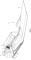
Figure 1 is a schematic perspective view, with parts removed for clarity, of a preferred embodiment of the car of the present invention; -
Figure 2 is a schematic bottom view, with parts removed for clarity, of the car inFigure 1 ; -
Figure 3 is a schematic perspective view, with parts removed for clarity, of a detail of the car inFigure 1 ; and -
Figures 4-6 are three schematic perspective views, with parts in section and parts removed for clarity, of a detail ofFigure 3 . - With reference to
Figures 1 and2 , number 1 indicates, as a whole, a car, in particular a sports car, comprising asupport frame 2 defining part of alower floor 3 of the car 1. - The car 1 also comprises a
passenger compartment 4 mounted on theframe 2 and projecting upwards from thefloor 3, and anaerodynamic bottom 5 fixed to theframe 2 and defining part of thefloor 3. - The
bottom 5 comprises afront bottom 6 fixed to theframe 2 in the area of afront zone 7 of the car 1, arear bottom 8 fixed to theframe 2 in the area of arear zone 9 of the car 1, and an elongatedcentral bottom 10 fixed to theframe 2 between thebottoms central zone 11 of the car 1. - The car 1 further comprises an
engine 12 of a known type, which is mounted in the centre of therear zone 9 and is connected to tworear drive wheels 13 of the car 1 via the interposition of agearbox 14 of a known type. - The car 1 is also provided with at least one
clutch 15 of a known type to connect a drive shaft (not shown) of theengine 12 and an input shaft (not shown) of thegearbox 14 to one another in a releasable manner. - As shown in
Figures 2 ,3 , and4 , therear bottom 8 comprises afront plate 16 and a rear box-shaped body 17 arranged in succession along therear zone 9 of the car 1. - The
body 17 is bounded by alower wall 18 facing a road surface (not shown) and defines apneumatic chamber 19, which communicates with the outside through a plurality ofopenings 20 obtained through thewall 18. - The
chamber 19 defines part of apneumatic unit 21 comprising also, in this case, acompressor device 22, which is mounted on thebody 17, is provided with anair vent 23 communicating with the outside, and is pneumatically connected to thechamber 19. - The
compressor device 22 is operated to blow an air flow F1 out of thechamber 19 through theopenings 20 and in the direction of the road surface (not shown) to selectively control the aerodynamic set-up of the car 1 according to an operating parameter, e.g. the speed, of the car 1 and/or a geometric parameter of a driving path (not shown) of the car 1. - The
device 22 has atransmission shaft 24 connected to the aforementioned input shaft (not shown) or to anoutput shaft 25 of thegearbox 14 via the interposition of atrain 26 ofgears 27, one of which is splined on the input shaft (not shown) or on theoutput shaft 25 of thegearbox 14 and the other is connected in a releasable manner to theshaft 24 via the interposition of aclutch 28. - According to a variant not shown, the
compressor device 22 is removed and replaced by a suction device operated to draw into thechamber 19 through theopenings 20 part of an air flow F2 flowing under thefloor 3 from thefront zone 7 to therear zone 9 during the normal operation of the car 1 to selectively control the aerodynamic set-up of the car 1 according to an operating parameter, e.g. the speed, of the car 1 and/or a geometric parameter of a driving path (not shown) of the car 1. - According to a further variant, not shown, the
compressor device 22 is removed and replaced by a reversible pneumatic device having a first mode of operation, in which the reversible pneumatic device is operated to blow the air flow F1 out of thechamber 19 through theopenings 20, and a second mode of operation, in which the reversible pneumatic device is operated to suck into thechamber 19 through theopenings 20 part of the air flow F2 flowing under thefloor 3 of the car 1. - Since the
pneumatic unit 21 is operated by thegearbox 14 via the interposition of thetrain 26 ofgears 27 andclutch 28, thepneumatic unit 21 is relatively simple and inexpensive and the car 1 has relatively low weight and small overall dimensions.
Claims (8)
- A car comprising a support frame (2) defining part of a lower floor (3) of the car; a passenger compartment (4) projecting upwards from the lower floor (3); an engine (12) to move the car; two drive wheels (13); a gearbox (14), which is interposed between the engine (12) and the drive wheels (13) and has at least one input shaft connected to a drive shaft of the engine (12) and at least one output shaft (25) connected to the drive wheels (13); an aerodynamic bottom (5), which is at least partly fixed to the support frame (2), defines part of the lower floor (3) and comprises, in turn, a rear bottom (8), which is mounted in the area of a rear zone (9) of the car and is provided with a pneumatic unit (21) configured to blow a first air flow (F1) in the direction of a road surface and/or to suck part of a second air flow (F2) flowing under the lower floor (3) during the normal operation of the car; and characterized by the fact that it further comprises a coupling device (26) to connect a transmission shaft (24) of the pneumatic unit (21) and the input shaft or the output shaft (25) of the gearbox (14) to one another so as to operate the pneumatic unit (21) through the gearbox (14) .
- The car according to claim 1 and further comprising at least one first clutch (15) to connect the drive shaft of the engine (12) and the input shaft of the gearbox (14) to one another in a releasable manner.
- The car according to claim 1 or 2 and further comprising at least one second clutch (28) to connect the transmission shaft (24) of the pneumatic unit (21) and the input shaft or the output shaft (25) of the gearbox (14) to one another in a releasable manner.
- The car according to any one of the preceding claims, wherein the pneumatic unit (21) comprises at least one reversible pneumatic device configured both to blow the first air flow (F1) in the direction of the road surface and to suck part of the second air flow (F2); the coupling device (26) being configured to connect the transmission shaft (24) of the reversible pneumatic device and the input shaft or the output shaft (25) of the gearbox (14) to one another.
- The car according to any one of the claims from 1 to 3, wherein the pneumatic unit (21) comprises a pneumatic blowing device to blow the first air flow (F1); the coupling device (26) being configured to connect the transmission shaft (24) of the pneumatic blowing device and the input shaft or the output shaft (25) of the gearbox (14) to one another.
- The car according to any one of the claims from 1 to 3 or 5, wherein the pneumatic unit (21) comprises a pneumatic sucking device to suck part of the second air flow (F2); the coupling device (26) being configured to connect the transmission shaft (24) of the pneumatic sucking device and the input shaft or the output shaft (25) of the gearbox (14) to one another.
- The car according to any one of the preceding claims, wherein the pneumatic unit (21) comprises a pneumatic chamber (19) obtained in the rear bottom (8) and a plurality of openings (20) obtained through a lower wall (18) of the rear bottom (8) in order to connect the pneumatic chamber (19) to the outside under the lower floor (3) .
- The car according to any one of the preceding claims, wherein the coupling device (26) comprises a train of gears (27), one of them splined on the input shaft or on the output shaft (25) of the gearbox (14) and one of them being connected to the transmission shaft (24) of the pneumatic unit (21).
Applications Claiming Priority (1)
| Application Number | Priority Date | Filing Date | Title |
|---|---|---|---|
| IT102023000003864A IT202300003864A1 (en) | 2023-03-03 | 2023-03-03 | AUTOMOBILE EQUIPPED WITH A PNEUMATIC UNIT ACTIVATED BY A GEARBOX |
Publications (1)
| Publication Number | Publication Date |
|---|---|
| EP4431375A1 true EP4431375A1 (en) | 2024-09-18 |
Family
ID=86469362
Family Applications (1)
| Application Number | Title | Priority Date | Filing Date |
|---|---|---|---|
| EP24160671.4A Pending EP4431375A1 (en) | 2023-03-03 | 2024-02-29 | Car provided with a pneumatic unit operated by a gearbox |
Country Status (4)
| Country | Link |
|---|---|
| US (1) | US12612121B2 (en) |
| EP (1) | EP4431375A1 (en) |
| CN (1) | CN118578865A (en) |
| IT (1) | IT202300003864A1 (en) |
Families Citing this family (4)
| Publication number | Priority date | Publication date | Assignee | Title |
|---|---|---|---|---|
| IT202200019344A1 (en) * | 2022-09-21 | 2024-03-21 | Ferrari Spa | CAR |
| USD1117294S1 (en) * | 2023-04-26 | 2026-03-10 | Ferrari S.P.A. | Display screen with a graphical user interface |
| CN119099734A (en) * | 2023-06-07 | 2024-12-10 | 本田技研工业株式会社 | Vehicle bottom structure |
| USD1086964S1 (en) * | 2023-10-23 | 2025-08-05 | Mazda Motor Corporation | Motor vehicle |
Citations (4)
| Publication number | Priority date | Publication date | Assignee | Title |
|---|---|---|---|---|
| WO1988009737A1 (en) * | 1987-06-02 | 1988-12-15 | Ital Idee S.R.L. | Apparatus for sucking the boundary layer of aerodynamic surfaces, in particular for sports cars provided with an internal combustion engine |
| JPH04339079A (en) * | 1991-05-13 | 1992-11-26 | Yamaha Motor Co Ltd | Device for improving aerodynamic characteristic of car |
| EP0607270B1 (en) * | 1991-10-09 | 1995-12-20 | Ab Volvo | A device for control of the airstreams underneath a moving vehicle |
| EP2193984A1 (en) * | 2008-12-03 | 2010-06-09 | Dr. Ing. h.c. F. Porsche AG | Device for convective cooling of a power transmission component of a motor vehicle |
Family Cites Families (5)
| Publication number | Priority date | Publication date | Assignee | Title |
|---|---|---|---|---|
| US6068328A (en) * | 1997-11-25 | 2000-05-30 | Gazdzinski; Robert F. | Vehicular boundary layer control system and method |
| EP1752364A1 (en) * | 2005-08-09 | 2007-02-14 | Actiflow B.V. | Boundary layer suction system for a vehicle |
| US9950611B2 (en) * | 2016-03-15 | 2018-04-24 | Ford Global Technologies, Llc | Aerodynamic body panel system for air flow management at a rear underside of a motor vehicle |
| DE102019000358A1 (en) * | 2019-01-18 | 2020-07-23 | Daimler Ag | vehicle |
| GB2611957B (en) * | 2019-10-21 | 2024-02-07 | Mcmurtry Automotive Ltd | Downforce system for a vehicle |
-
2023
- 2023-03-03 IT IT102023000003864A patent/IT202300003864A1/en unknown
-
2024
- 2024-02-29 US US18/591,525 patent/US12612121B2/en active Active
- 2024-02-29 EP EP24160671.4A patent/EP4431375A1/en active Pending
- 2024-03-04 CN CN202410244376.0A patent/CN118578865A/en active Pending
Patent Citations (4)
| Publication number | Priority date | Publication date | Assignee | Title |
|---|---|---|---|---|
| WO1988009737A1 (en) * | 1987-06-02 | 1988-12-15 | Ital Idee S.R.L. | Apparatus for sucking the boundary layer of aerodynamic surfaces, in particular for sports cars provided with an internal combustion engine |
| JPH04339079A (en) * | 1991-05-13 | 1992-11-26 | Yamaha Motor Co Ltd | Device for improving aerodynamic characteristic of car |
| EP0607270B1 (en) * | 1991-10-09 | 1995-12-20 | Ab Volvo | A device for control of the airstreams underneath a moving vehicle |
| EP2193984A1 (en) * | 2008-12-03 | 2010-06-09 | Dr. Ing. h.c. F. Porsche AG | Device for convective cooling of a power transmission component of a motor vehicle |
Also Published As
| Publication number | Publication date |
|---|---|
| CN118578865A (en) | 2024-09-03 |
| US20240294216A1 (en) | 2024-09-05 |
| US12612121B2 (en) | 2026-04-28 |
| IT202300003864A1 (en) | 2024-09-03 |
Similar Documents
| Publication | Publication Date | Title |
|---|---|---|
| EP4431375A1 (en) | Car provided with a pneumatic unit operated by a gearbox | |
| EP4342773A1 (en) | Car | |
| US20110094811A1 (en) | All terrain vehicle | |
| EP2781390A1 (en) | Cooling airflow introduction structure | |
| US20170129306A1 (en) | Work vehicle | |
| CN1150098C (en) | Air conditioner for vehicle | |
| CN104884328B (en) | Vehicle air conditioner and the rail truck with the vehicle air conditioner | |
| EP1919758B1 (en) | Boundary layer suction system for a vehicle | |
| JP5104999B2 (en) | Interior parts for vehicles, method for manufacturing the same, and molding die thereof | |
| CN102514463A (en) | Back row air blowing mechanism for vehicle air conditioner | |
| JP2016094141A (en) | vehicle | |
| US8016070B2 (en) | Powertrain | |
| CN200996157Y (en) | Driver's cabs for engineering mechanical vehicles and vehicles therewith | |
| US20240083522A1 (en) | Car | |
| JP2017149304A (en) | Air blowing device for vehicle | |
| JP6213350B2 (en) | Air conditioner for vehicles | |
| KR100484117B1 (en) | Air resistance turbine for Vehicle | |
| EP4717483A1 (en) | Car provided with an air-conditioning system having a fan device arranged behind the passenger compartment | |
| CN114962772B (en) | In-car air pressure regulating valve | |
| CN210390639U (en) | Transaxle and vehicle having the same | |
| JP4475064B2 (en) | Work vehicle | |
| KR200280273Y1 (en) | Air releasing structure for preventing pressure rise of the constant velocity jointed propeller shaft for vehicles | |
| JP2004074910A (en) | Vehicle front body structure | |
| KR20230147874A (en) | Cowl cross bar for vehicle and cockpit module having the same | |
| JP2009292279A (en) | Arrangement structure of vehicular air-conditioning unit |
Legal Events
| Date | Code | Title | Description |
|---|---|---|---|
| PUAI | Public reference made under article 153(3) epc to a published international application that has entered the european phase |
Free format text: ORIGINAL CODE: 0009012 |
|
| STAA | Information on the status of an ep patent application or granted ep patent |
Free format text: STATUS: THE APPLICATION HAS BEEN PUBLISHED |
|
| AK | Designated contracting states |
Kind code of ref document: A1 Designated state(s): AL AT BE BG CH CY CZ DE DK EE ES FI FR GB GR HR HU IE IS IT LI LT LU LV MC ME MK MT NL NO PL PT RO RS SE SI SK SM TR |
|
| STAA | Information on the status of an ep patent application or granted ep patent |
Free format text: STATUS: REQUEST FOR EXAMINATION WAS MADE |
|
| 17P | Request for examination filed |
Effective date: 20250131 |