EP4431342A1 - Vehicular electronic device and production method therefor - Google Patents
Vehicular electronic device and production method therefor Download PDFInfo
- Publication number
- EP4431342A1 EP4431342A1 EP22892792.7A EP22892792A EP4431342A1 EP 4431342 A1 EP4431342 A1 EP 4431342A1 EP 22892792 A EP22892792 A EP 22892792A EP 4431342 A1 EP4431342 A1 EP 4431342A1
- Authority
- EP
- European Patent Office
- Prior art keywords
- sealing
- cover
- sealing region
- electronic device
- housing
- Prior art date
- Legal status (The legal status is an assumption and is not a legal conclusion. Google has not performed a legal analysis and makes no representation as to the accuracy of the status listed.)
- Pending
Links
Images





Classifications
-
- B—PERFORMING OPERATIONS; TRANSPORTING
- B60—VEHICLES IN GENERAL
- B60R—VEHICLES, VEHICLE FITTINGS, OR VEHICLE PARTS, NOT OTHERWISE PROVIDED FOR
- B60R16/00—Electric or fluid circuits specially adapted for vehicles and not otherwise provided for; Arrangement of elements of electric or fluid circuits specially adapted for vehicles and not otherwise provided for
- B60R16/02—Electric or fluid circuits specially adapted for vehicles and not otherwise provided for; Arrangement of elements of electric or fluid circuits specially adapted for vehicles and not otherwise provided for electric constitutive elements
-
- F—MECHANICAL ENGINEERING; LIGHTING; HEATING; WEAPONS; BLASTING
- F16—ENGINEERING ELEMENTS AND UNITS; GENERAL MEASURES FOR PRODUCING AND MAINTAINING EFFECTIVE FUNCTIONING OF MACHINES OR INSTALLATIONS; THERMAL INSULATION IN GENERAL
- F16J—PISTONS; CYLINDERS; SEALINGS
- F16J15/00—Sealings
- F16J15/02—Sealings between relatively-stationary surfaces
- F16J15/06—Sealings between relatively-stationary surfaces with solid packing compressed between sealing surfaces
- F16J15/10—Sealings between relatively-stationary surfaces with solid packing compressed between sealing surfaces with non-metallic packing
- F16J15/104—Sealings between relatively-stationary surfaces with solid packing compressed between sealing surfaces with non-metallic packing characterised by structure
- F16J15/106—Sealings between relatively-stationary surfaces with solid packing compressed between sealing surfaces with non-metallic packing characterised by structure homogeneous
-
- F—MECHANICAL ENGINEERING; LIGHTING; HEATING; WEAPONS; BLASTING
- F16—ENGINEERING ELEMENTS AND UNITS; GENERAL MEASURES FOR PRODUCING AND MAINTAINING EFFECTIVE FUNCTIONING OF MACHINES OR INSTALLATIONS; THERMAL INSULATION IN GENERAL
- F16J—PISTONS; CYLINDERS; SEALINGS
- F16J15/00—Sealings
- F16J15/02—Sealings between relatively-stationary surfaces
- F16J15/06—Sealings between relatively-stationary surfaces with solid packing compressed between sealing surfaces
- F16J15/10—Sealings between relatively-stationary surfaces with solid packing compressed between sealing surfaces with non-metallic packing
- F16J15/108—Special methods for making a non-metallic packing
-
- F—MECHANICAL ENGINEERING; LIGHTING; HEATING; WEAPONS; BLASTING
- F16—ENGINEERING ELEMENTS AND UNITS; GENERAL MEASURES FOR PRODUCING AND MAINTAINING EFFECTIVE FUNCTIONING OF MACHINES OR INSTALLATIONS; THERMAL INSULATION IN GENERAL
- F16J—PISTONS; CYLINDERS; SEALINGS
- F16J15/00—Sealings
- F16J15/02—Sealings between relatively-stationary surfaces
- F16J15/14—Sealings between relatively-stationary surfaces by means of granular or plastic material, or fluid
-
- H—ELECTRICITY
- H05—ELECTRIC TECHNIQUES NOT OTHERWISE PROVIDED FOR
- H05K—PRINTED CIRCUITS; CASINGS OR CONSTRUCTIONAL DETAILS OF ELECTRIC APPARATUS; MANUFACTURE OF ASSEMBLAGES OF ELECTRICAL COMPONENTS
- H05K5/00—Casings, cabinets or drawers for electric apparatus
- H05K5/06—Hermetically-sealed casings
- H05K5/062—Hermetically-sealed casings sealed by a material injected between a non-removable cover and a body, e.g. hardening in situ
Definitions
- the present invention relates to a vehicular electronic device which is placed in an equipment placement room and operated by being energized.
- Patent Document 1 discloses, as a vehicular electronic device, a fluid heating device that heats a fluid with a heater.
- Patent document 2 discloses an electric compressor as a vehicular electronic device used in an air conditioner.
- vehicular electronic devices are similar to each other in that the vehicular electronic devices include a housing in which an internal space including an opening is formed and a circuit board is accommodated, a cover that covers the opening of the housing, and a sealing member that is sandwiched between the housing and the cover and prevents dust and the like from entering into the housing.
- Some vehicular electronic devices are provided in an equipment placement room (for example, a vehicle front compartment in which an engine and a radiator are placed) partitioned separately from a passenger compartment configured to accommodate a passenger. Water splashed from a puddle or the like on a road surface may be scattered inside the equipment placement room.
- the housing or the cover of a vehicular electronic device is made of metal, such water causes rust. From the viewpoint of extending a product life, it is desired to suppress the rust from spreading to the inner circumferential surface of the housing or the cover.
- An object of the invention is to provide a vehicular electronic device that can achieve a long service life.
- a vehicular electronic device provided in an equipment placement room (12) partitioned separately from a passenger compartment (11) configured to accommodate a passenger, the vehicular electronic device including:
- a method for producing a vehicular electronic device which is provided in an equipment placement room (12) partitioned separately from a passenger compartment (11) configured to accommodate a passenger and is operated by being energized, the method including:
- a vehicular electronic device that can achieve a long service life can be provided.
- FIG. 1 illustrates a vehicle 10.
- the vehicle 10 is, for example, a passenger vehicle and includes a passenger compartment 11 configured to accommodate a passenger and an equipment placement room 12 provided in front of the passenger compartment 11 and partitioned by a partition wall (not illustrated).
- the equipment placement room 12 is, for example, an engine room and accommodates an engine, vehicular electronic devices 20 and 20A, and the like.
- the vehicular electronic devices 20 and 20A are, for example, a liquid heating device and an electric compressor.
- the vehicular electronic device 20 (hereinafter, abbreviated as the "electronic device 20") as a liquid heating device will be described as an example.
- the electronic device 20A as an electric compressor is the same in the configuration of a main part, and thus detailed descriptions thereof will be omitted.
- the electronic device 20 is a device for heating circulating water. Heated water is fed to a heating heat exchanger disposed in the passenger compartment 11 (see FIG. 1 ) and used as a heat source for heating the interior of the passenger compartment 11.
- the electronic device 20 includes; a housing 30 which is made of metal and which includes an internal space Sp including an opening 31 at an upper surface (a housing 30 made of metal and formed with an internal space Sp including an opening 31 at an upper surface); a circuit board 22 accommodated in the internal space Sp and configured to be energized; a cover 40 made of metal and configured to cover the opening 31; and a sealing member 50 sandwiched between the housing 30 and the cover 40 and configured to prevent dust from entering into the internal space Sp.
- the housing 30 has a substantially cuboid shape opening at an upper surface.
- the housing 30 is made of, for example, an aluminum alloy.
- the housing 30 is formed with a circuit board accommodation internal space (not illustrated) accommodating the circuit board 22 and a heater accommodation internal space (not illustrated) which is partitioned separately from the circuit board accommodation internal space and in which a heater for heating water is accommodated.
- the housing 30 includes a housing side surface portion 32 formed in a substantially rectangular tube shape.
- the opening 31 is a portion surrounded by an upper end of the housing side surface portion 32.
- An introduction port 32a for introducing water into the heater accommodation internal space and a discharge port 32b for discharging heated water are opened in the housing side surface portion 32.
- circuit board 22 for example, a printed circuit board formed by printing a circuit on a surface of a glass substrate can be used.
- the heater can heat circulating water by being operated via the circuit board 22.
- the cover 40 is made of an aluminum alloy.
- the cover 40 includes a cover main body 41 which has the substantially same shape as the opening 31 of the housing 30 and covers the internal space Sp, and a cover side surface portion 42 extending from a circumferential edge of the cover main body 41 toward an edge of the opening 31 of the housing 30 (the housing side surface portion 32).
- the lower end of the cover side surface portion 42 faces the upper end of the housing side surface portion 32.
- the sealing member 50 is made of, for example, two-component silicone rubber. More specifically, Silastic W3-3636, which is a sealant made by Dow Chemical, can be used.
- the sealing member 50 has a shape in which a substantially T-shaped cross section continuously makes a round.
- the sealing member 50 includes: a first sealing region 51 formed over an entire circumference so as to be sandwiched between an edge of the opening 31 and an edge of the cover 40; a second sealing region 52 formed so as to be continuous from an end portion of the first sealing region 51 and adhered to an outer circumferential surface of the housing 30; and a third sealing region 53 formed so as to be continuous from an end portion of the first sealing region 51 and adhered to an outer circumferential surface of the cover 40.
- the first sealing region 51, the second sealing region 52, and the third sealing region 53 are integrally formed of a single member.
- the thickness of the second sealing region 52 and the thickness of the third sealing region 53 are thinner than the thickness of the first sealing region 51. The reason therefor will be described below. Similar to the first sealing region 51, the second sealing region 52 and the third sealing region 53 are formed over the entire circumference.
- a method for producing the electronic device 20 described above, in particular, a method for forming the sealing member 50 will be described below.
- the housing 30 made of metal and formed with the internal space Sp including the opening 31, the circuit board 22 that can be energized, and the cover 40 made of metal are prepared (preparation step).
- plasma treatment is performed on the surface of the prepared housing 30 and the surface of the prepared cover 40 (plasma surface treatment step).
- the plasma treatment is surely performed on, in particular, a leading end of the housing side surface portion 32 and a leading end of the cover side surface portion 42, in addition to the opening 31 of the housing 30 and a surface of the cover 40 facing the opening 31.
- a known device and a known method can be used as the plasma treatment and a device necessary for the plasma treatment.
- masking is performed on the outer circumferential surface of the housing 30 and the outer circumferential surface of the cover 40 which have been subjected to the plasma treatment (masking step).
- the masking is performed by attaching masking tapes 61 and 61 on the outer circumferential surface of the housing 30 and the outer circumferential surface of the cover 40, respectively.
- circuit board accommodation step Next, the circuit board 22 is accommodated in the internal space Sp of the housing 30 (circuit board accommodation step).
- a sealing material 62 is applied to an edge of the opening 31 of the housing 30 in which the circuit board 22 is accommodated (sealing material application step).
- the sealing material 62 can be said to be a material of the sealing member 50 (see FIG. 3 ) which becomes the sealing member 50 by being cured.
- the sealing material 62 has a certain fluidity.
- the sealing material application step may be performed on only the leading end of the housing side surface portion 32, or may be performed on both of the leading end of the housing side surface portion 32 and the leading end of the cover side surface portion 42. Alternatively, this step may be performed on only the leading end of the cover side surface portion 42.
- a shield member 63 may be disposed on an inner circumferential surface side so as to prevent leakage of the sealing material 62 to the inner circumferential surface side. A certain amount of the sealing material 62 leaks out on an outer circumferential surface side.
- the sealing material 62 leaked out from between the housing 30 and the cover 40 by being sandwiched is pressed against the outer circumferential surfaces of the housing 30 and the cover 40 and left until cured.
- sealing material 62 is cured, sealing between the housing 30 and the cover 40 is achieved (sealing step) .
- the sealing material 62 is cured to be the sealing member 50, the masking tapes 61 and 61 are removed (masking removal step). Accordingly, the electronic device 20 is completed.
- the electronic device 20 will be summarized below.
- the electronic device 20 is provided in the equipment placement room 12 partitioned separately from the passenger compartment 11 configured to accommodate a passenger.
- the electronic device 20 includes; the housing 30 made of metal and formed with the internal space Sp including the opening 31; the circuit board 22 accommodated in the internal space Sp and configured to be energized; the cover 40 made of metal and configured to cover the opening 31; and the sealing member 50 sandwiched between the housing 30 and the cover 40 and configured to prevent dust from entering into the internal space Sp.
- FIG. 4 refer also to FIG. 4 .
- the sealing member 50 includes: a first sealing region 51 formed over an entire circumference so as to be sandwiched between an edge of the opening 31 and an edge of the cover 40; a second sealing region 52 formed so as to be continuous from an end portion of the first sealing region 51 and adhered to an outer circumferential surface of the housing 30; and a third sealing region 53 formed so as to be continuous from an end portion of the first sealing region 51 and adhered to an outer circumferential surface of the cover 40.
- the method for producing the electronic device 20 includes: the preparation step of preparing the housing 30 made of metal and formed with the internal space Sp including the opening 31, the circuit board 22 configured to be energized, and the cover 40 made of metal; the circuit board accommodation step of accommodating the circuit board 22 in the internal space Sp, the circuit board accommodation step being a step after the preparation step; the sealing material application step of applying the sealing material 62 to an edge of the opening 31 and/or an edge of the cover 40, the sealing material application step being a step after the circuit board accommodation step; the sealing material sandwiching step of sandwiching the sealing material 62 between the edge of the opening 31 and the edge of the cover 40 caused to face each other, the sealing material sandwiching step being a step after the sealing material application step; and the sealing step of performing sealing by pressing the sealing material 62 protruded from between the edge of the opening 31 and the edge of the cover 40 in the sealing material sandwiching step against outer circumferential surfaces of the housing 30 and the cover 40.
- FIG. 6A illustrates an electronic device 120 according to Comparative Example 1.
- Water or the like scattering from the outside of the vehicle into the equipment placement room 12 may adhere to the outer circumferential surface of a housing 130 and a cover 140.
- the attached water may cause rust, and the rust may be spread through between the housing 130 and a sealing member 150 or through between the cover 140 and the sealing member 150 to the inside of the housing 130 or the cover 140.
- FIG. 6B illustrates an electronic device 220 according to Comparative Example 2.
- a housing 230 or a cover 240 In order to increase a time until rust is spread to the inner circumferential surface of a housing 230 or a cover 240, it is conceivable to extend an edge of the housing 230 or an edge of the cover 240 toward an outer circumferential surface side in contrast to the case of FIG. 6A .
- Many devices such as a device 66 are provided inside the equipment placement room 12 in which the electronic device 220 is provided.
- the vehicle 10 mounted with the electronic device 220 vibrates during traveling. For this reason, when the edge of the housing 230 or the edge of the cover 240 is extended to the outer circumferential surface side, the possibility of interference between the electronic device 220 and other devices such as the device 66 is increased due to vibration, which is not preferable.
- FIG. 6C illustrates the electronic device 20 according to Example.
- the sealing member 50 includes: the second sealing region 52 formed so as to be continuous from an end portion of the first sealing region 51 and adhered to an outer circumferential surface of the housing 30; and the third sealing region 53 formed so as to be continuous from an end portion of the first sealing region 51 and adhered to an outer circumferential surface of the cover 40.
- the second sealing region 52 and the third sealing region 53 it is possible to prevent water from the outside of the vehicle from adhering to the vicinities of the edge of the housing 30 and the edge of the cover 40. This can increase a time until rust is spread from the outer circumferential surfaces to the inner circumferential surfaces of the housing 30 and the cover 40.
- the service life of the vehicular electronic device 20 can be increased without increasing the thicknesses of the housing 30 and the cover 40.
- the second sealing region 52 and the third sealing region 53 can be formed by pressing the sealing material 62 protruded from between the edge of the opening 31 and the edge of the cover 40 in the sealing material sandwiching step (see 5E) against the outer circumferential surfaces of the housing 30 and the cover 40 (the sealing step, see 5F). This is preferable because the second sealing region 52 and the third sealing region 53 can be easily formed.
- the first sealing region 51, the second sealing region 52, and the third sealing region 53 are integrally formed of a single member. By integrally forming the first sealing region 51 to the third sealing region 53 with a single member, it is possible to eliminate boundary portions between the respective sealing regions and increase the corrosion resistance.
- the thickness of the second sealing region 52 and the thickness of the third sealing region 53 are thinner than the thickness of the first sealing region 51. By making the thicknesses of the second sealing region 52 and the third sealing region 53 thinner, it is possible to prevent interference with other devices such as the device 66 and increase the service life of the electronic device 20. Further, by making the thickness of the second sealing region 52 and the thickness of the third sealing region 53 thinner, the curing time of the sealing material 61 in these regions can be reduced.
- a plasma surface treatment step of irradiating the edge of the opening 31 and the edge of the cover 40 with plasma can be performed before the circuit board accommodation step.
- a plasma surface treatment step By preliminarily performing the plasma surface treatment step, it is possible to increase the adherence of the sealing member 50 and improve the corrosion resistance.
- Example 2 an electronic device 20B according to Example 2 will be described with reference to the drawing.
- the same parts as those in Example 1 are denoted by the same reference signs, and the detailed descriptions thereof will be omitted.
- FIG. 7 illustrates a cross-sectional configuration of the electronic device 20B according to Example 2.
- a sealing member 50B of the electronic device 20B according to Example 2 includes two members. That is, a member constituting a first sealing region 51B and a member constituting a second sealing region 52B and a third sealing region 53B are different from each other.
- first sealing region 51B and the second sealing region 52B may be made of the same material and only the third sealing region 53B may be made of a different material, or the first sealing region 51B and the third sealing region 53B may be made of the same material and only the second sealing region 52B may be made of a different material.
- the sealing member 50B includes: the first sealing region 51B formed over an entire circumference so as to be sandwiched between an edge of the opening 31 and an edge of the cover 40; the second sealing region 52B formed so as to be continuous from an end portion of the first sealing region 51B and adhered to an outer circumferential surface of a housing 30B; and the third sealing region 53B formed so as to be continuous from an end portion of the first sealing region 51B and adhered to an outer circumferential surface of the cover.
- the first sealing region 51B can be made of a two-component sealing material, and the second sealing region 52B and the third sealing region 53B can be made of an insulating tape.
- the workability in the sealing step can be facilitated.
- a sealing material having a relatively short curing time may be used for the first sealing region 51B, and a sealing material having a relatively long curing time may be used for the second sealing region 52B and the third sealing region 53B.
- the second and third sealing regions 52B and 53B which are easy to visually check, are cured, it can be determined that the first sealing region 51B is also cured, and thus the workability in the sealing step can be streamlined.
- materials suitable for respective purposes can be used.
- the first sealing region 51B is made of a material having a high sealability
- the second sealing region 52B and the third sealing region 53B are made of a material which is thin in thickness and can prevent the spread of rust.
- the electronic device 20B described above achieves predetermined effects of the invention.
- the electronic device according to the invention has been described using an example in which the electronic device is mounted in the equipment placement room 12 formed in front of the passenger compartment 11 configured to accommodate a passenger. However, the electronic device may be also applied to a case in which the electronic device is mounted in an equipment placement room formed in the rear of or below the passenger compartment 11.
- a vehicle in which the electronic device is mounted is not limited to a vehicle driven by an engine, but may be an electric vehicle or a hydrogen vehicle.
- An aluminum alloy is used as an example of a material of the housing and the cover, but any metals such as an SUS material can be selected. In addition, different materials may be selected for the housing and the cover.
- the opening 31 provided in the housing 30 may be opened, not at the upper surface, but toward a front-rear direction or a right-left direction. Further, the housing 30 may have a shape other than a substantially cuboid shape.
- the internal space Sp is formed with a circuit board accommodation internal space (not illustrated) and a refrigerant compressing internal space (not illustrated) which is partitioned separately from the circuit board accommodation internal space and configured to suck and compress a refrigerant.
- the housing 30 and the cover 40 of the electronic device 20A may be fastened outside the first sealing region 51 with some fastening members (bolts or the like).
- the second sealing region 52 and the third sealing region 53 are continuous with end portions of the first sealing region 51 between the fastening members.
- the second sealing region 52 is provided on the outer circumference of the opening 31 of the housing 30 on an outer side of the fastening members
- the third sealing region 53 is provided on the outer circumference of a leading end of the cover side surface portion 42 on an outer side of the fastening members.
- the second sealing region 52 and the third sealing region 53 are not continuous with the end portions of the first sealing region 51 at the portions at which the fastening members are provided.
- the invention is not limited to Examples as long as the actions and effects of the invention are achieved.
- the electronic device according to the invention is suitable for being mounted in an equipment placement room of a passenger vehicle.
Landscapes
- Engineering & Computer Science (AREA)
- General Engineering & Computer Science (AREA)
- Mechanical Engineering (AREA)
- Microelectronics & Electronic Packaging (AREA)
- Casings For Electric Apparatus (AREA)
Abstract
Description
- The present invention relates to a vehicular electronic device which is placed in an equipment placement room and operated by being energized.
- In many vehicles, a vehicular electronic device which is operated by being energized is placed in an equipment placement room. As the related art pertaining to a vehicular electronic device, there are techniques disclosed in
Patent Documents -
Patent Document 1 discloses, as a vehicular electronic device, a fluid heating device that heats a fluid with a heater.Patent document 2 discloses an electric compressor as a vehicular electronic device used in an air conditioner. - These vehicular electronic devices are similar to each other in that the vehicular electronic devices include a housing in which an internal space including an opening is formed and a circuit board is accommodated, a cover that covers the opening of the housing, and a sealing member that is sandwiched between the housing and the cover and prevents dust and the like from entering into the housing.
-
- Patent Document 1:
JP2017-72293A - Patent Document 2:
JP2015-17577A - Some vehicular electronic devices are provided in an equipment placement room (for example, a vehicle front compartment in which an engine and a radiator are placed) partitioned separately from a passenger compartment configured to accommodate a passenger. Water splashed from a puddle or the like on a road surface may be scattered inside the equipment placement room. When the housing or the cover of a vehicular electronic device is made of metal, such water causes rust. From the viewpoint of extending a product life, it is desired to suppress the rust from spreading to the inner circumferential surface of the housing or the cover.
- That is, it is desired to provide a vehicular electronic device that can achieve a long service life.
- An object of the invention is to provide a vehicular electronic device that can achieve a long service life.
- In the following description, for the purpose of facilitating the understanding about the invention, reference signs in the accompanying drawings are described in parentheses, but the invention is not limited to the configurations illustrated in the drawings.
- According to an aspect of the present disclosure, there is provided a vehicular electronic device provided in an equipment placement room (12) partitioned separately from a passenger compartment (11) configured to accommodate a passenger, the vehicular electronic device including:
- a housing (30) made of metal and formed with an internal space (Sp) including an opening (31);
- a circuit board (22) accommodated in the internal space (Sp) and configured to be energized;
- a cover (40) made of metal and configured to cover the opening (31); and
- a sealing member (50; 50B) sandwiched between the housing (30) and the cover (40) and configured to prevent dust from entering into the internal space (Sp),
- the sealing member (50; 50B) including
- a first sealing region (51; 51B) formed over an entire circumference so as to be sandwiched between an edge of the opening (31) and an edge of the cover (40),
- a second sealing region (52; 52B) formed so as to be continuous from an end portion of the first sealing region (51; 51B) and adhered to an outer circumferential surface of the housing (30), and
- a third sealing region (53; 53B) formed so as to be continuous from an end portion of the first sealing region (51; 51B) and adhered to an outer circumferential surface of the cover.
- According to another aspect of the present disclosure, there is provided a method for producing a vehicular electronic device which is provided in an equipment placement room (12) partitioned separately from a passenger compartment (11) configured to accommodate a passenger and is operated by being energized, the method including:
- a preparation step of preparing
- a housing (30) made of metal and formed with an internal space (Sp) including an opening (31),
- a circuit board (22) configured to be energized, and
- a cover (40) made of metal;
- a circuit board accommodation step of accommodating the circuit board (22) in the internal space (Sp), the circuit board accommodation step being a step after the preparation step;
- a sealing material application step of applying a sealing material to an edge of the opening (31) and/or an edge of the cover (40), the sealing material application step being a step after the circuit board accommodation step;
- a sealing material sandwiching step of sandwiching the sealing material (62) between the edge of the opening (31) and the edge of the cover (40) caused to face each other, the sealing material sandwiching step being a step after the sealing material application step; and
- a sealing step of performing sealing by pressing the sealing material (62) protruded from between the edge of the opening (31) and the edge of the cover (40) in the sealing material sandwiching step against outer circumferential surfaces of the housing (30) and the cover (40).
- According to the invention, a vehicular electronic device that can achieve a long service life can be provided.
-
- [
FIG. 1] FIG. 1 is a schematic diagram of a vehicle mounted with a vehicular electronic device according to Example 1. - [
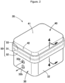
FIG. 2] FIG. 2 is a perspective view of the vehicular electronic device illustrated inFIG. 1 . - [
FIG. 3] FIG. 3 is an exploded perspective view of the vehicular electronic device illustrated inFIG. 2 . - [
FIG. 4] FIG. 4 is a cross-sectional view taken along a 4-4 line inFIG. 2 . - [
FIG. 5 ] 5A is a diagram illustrating a plasma surface treatment step, 5B is a diagram illustrating a masking step, 5C is a diagram illustrating a circuit board accommodation step, 5D is a diagram illustrating a sealing material application step, 5E is a diagram illustrating a sealing material sandwiching step, 5F is a diagram illustrating a sealing step, and 5G is a diagram illustrating a masking removal step. - [
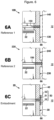
FIG. 6 ] 6A is a diagram illustrating problems in a vehicular electronic device according to Comparative Example 1, 6B is a diagram illustrating problems in a vehicular electronic device according to Comparative Example 2, and 6C is a diagram illustrating problems in a vehicular electronic device according to Example. - [
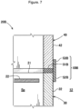
FIG. 7] FIG. 7 is a cross-sectional view of a vehicular electronic device according to Example 2. - Embodiments of the invention will be described below with reference to the accompanying drawings.
- Refer to
FIG. 1. FIG. 1 illustrates avehicle 10. Thevehicle 10 is, for example, a passenger vehicle and includes apassenger compartment 11 configured to accommodate a passenger and anequipment placement room 12 provided in front of thepassenger compartment 11 and partitioned by a partition wall (not illustrated). Theequipment placement room 12 is, for example, an engine room and accommodates an engine, vehicularelectronic devices - The vehicular
electronic devices electronic device 20") as a liquid heating device will be described as an example. However, theelectronic device 20A as an electric compressor is the same in the configuration of a main part, and thus detailed descriptions thereof will be omitted. - Refer to
FIG. 2 andFIG. 3 . Theelectronic device 20 is a device for heating circulating water. Heated water is fed to a heating heat exchanger disposed in the passenger compartment 11 (seeFIG. 1 ) and used as a heat source for heating the interior of thepassenger compartment 11. - The
electronic device 20 includes; ahousing 30 which is made of metal and which includes an internal space Sp including anopening 31 at an upper surface (ahousing 30 made of metal and formed with an internal space Sp including anopening 31 at an upper surface); acircuit board 22 accommodated in the internal space Sp and configured to be energized; acover 40 made of metal and configured to cover theopening 31; and a sealingmember 50 sandwiched between thehousing 30 and thecover 40 and configured to prevent dust from entering into the internal space Sp. - The
housing 30 has a substantially cuboid shape opening at an upper surface. Thehousing 30 is made of, for example, an aluminum alloy. Thehousing 30 is formed with a circuit board accommodation internal space (not illustrated) accommodating thecircuit board 22 and a heater accommodation internal space (not illustrated) which is partitioned separately from the circuit board accommodation internal space and in which a heater for heating water is accommodated. - The
housing 30 includes a housingside surface portion 32 formed in a substantially rectangular tube shape. Theopening 31 is a portion surrounded by an upper end of the housingside surface portion 32. Anintroduction port 32a for introducing water into the heater accommodation internal space and adischarge port 32b for discharging heated water are opened in the housingside surface portion 32. - As the
circuit board 22, for example, a printed circuit board formed by printing a circuit on a surface of a glass substrate can be used. The heater can heat circulating water by being operated via thecircuit board 22. - The
cover 40 is made of an aluminum alloy. Thecover 40 includes a covermain body 41 which has the substantially same shape as theopening 31 of thehousing 30 and covers the internal space Sp, and a coverside surface portion 42 extending from a circumferential edge of the covermain body 41 toward an edge of theopening 31 of the housing 30 (the housing side surface portion 32). - The lower end of the cover
side surface portion 42 faces the upper end of the housingside surface portion 32. - Refer to
FIG. 3 andFIG. 4 . The sealingmember 50 is made of, for example, two-component silicone rubber. More specifically, Silastic W3-3636, which is a sealant made by Dow Chemical, can be used. - The sealing
member 50 has a shape in which a substantially T-shaped cross section continuously makes a round. The sealingmember 50 includes: afirst sealing region 51 formed over an entire circumference so as to be sandwiched between an edge of theopening 31 and an edge of thecover 40; asecond sealing region 52 formed so as to be continuous from an end portion of thefirst sealing region 51 and adhered to an outer circumferential surface of thehousing 30; and athird sealing region 53 formed so as to be continuous from an end portion of thefirst sealing region 51 and adhered to an outer circumferential surface of thecover 40. Thefirst sealing region 51, thesecond sealing region 52, and thethird sealing region 53 are integrally formed of a single member. - The thickness of the
second sealing region 52 and the thickness of thethird sealing region 53 are thinner than the thickness of thefirst sealing region 51. The reason therefor will be described below. Similar to thefirst sealing region 51, thesecond sealing region 52 and thethird sealing region 53 are formed over the entire circumference. - A method for producing the
electronic device 20 described above, in particular, a method for forming the sealingmember 50 will be described below. - First, the
housing 30 made of metal and formed with the internal space Sp including theopening 31, thecircuit board 22 that can be energized, and thecover 40 made of metal are prepared (preparation step). - Refer to
FIG. 5A . Next, plasma treatment is performed on the surface of theprepared housing 30 and the surface of the prepared cover 40 (plasma surface treatment step). The plasma treatment is surely performed on, in particular, a leading end of the housingside surface portion 32 and a leading end of the coverside surface portion 42, in addition to theopening 31 of thehousing 30 and a surface of thecover 40 facing theopening 31. As the plasma treatment and a device necessary for the plasma treatment, a known device and a known method can be used. - By performing the plasma treatment, oil and fat components and dust adhering to the surfaces of the housing and the cover can be removed, and the metal surfaces can be activated so that the chemical bonding force with the sealing
member 50 is increased. This can increase corrosion resistance. - Refer to
FIG. 5B . Next, masking is performed on the outer circumferential surface of thehousing 30 and the outer circumferential surface of thecover 40 which have been subjected to the plasma treatment (masking step). For example, the masking is performed by attachingmasking tapes housing 30 and the outer circumferential surface of thecover 40, respectively. - Refer to
FIG. 5C . Next, thecircuit board 22 is accommodated in the internal space Sp of the housing 30 (circuit board accommodation step). - Refer to
FIG. 5D . A sealingmaterial 62 is applied to an edge of theopening 31 of thehousing 30 in which thecircuit board 22 is accommodated (sealing material application step). The sealingmaterial 62 can be said to be a material of the sealing member 50 (seeFIG. 3 ) which becomes the sealingmember 50 by being cured. The sealingmaterial 62 has a certain fluidity. - The sealing material application step may be performed on only the leading end of the housing
side surface portion 32, or may be performed on both of the leading end of the housingside surface portion 32 and the leading end of the coverside surface portion 42. Alternatively, this step may be performed on only the leading end of the coverside surface portion 42. - Refer to
FIG. 5E . Next, the edge of thecover 40 is caused to face the edge of theopening 31 and the sealingmaterial 62 is sandwiched between these edges (sealing material sandwiching step). In performing the sealing member sandwiching step, ashield member 63 may be disposed on an inner circumferential surface side so as to prevent leakage of the sealingmaterial 62 to the inner circumferential surface side. A certain amount of the sealingmaterial 62 leaks out on an outer circumferential surface side. - Refer to
FIG. 5F . The sealingmaterial 62 leaked out from between thehousing 30 and thecover 40 by being sandwiched is pressed against the outer circumferential surfaces of thehousing 30 and thecover 40 and left until cured. When the sealingmaterial 62 is cured, sealing between thehousing 30 and thecover 40 is achieved (sealing step) . - Refer to
FIG. 5G . After the sealingmaterial 62 is cured to be the sealingmember 50, the maskingtapes electronic device 20 is completed. - The
electronic device 20 will be summarized below. - Refer to
FIG. 1 . Theelectronic device 20 is provided in theequipment placement room 12 partitioned separately from thepassenger compartment 11 configured to accommodate a passenger. Refer toFIG. 3 . Theelectronic device 20 includes; thehousing 30 made of metal and formed with the internal space Sp including theopening 31; thecircuit board 22 accommodated in the internal space Sp and configured to be energized; thecover 40 made of metal and configured to cover theopening 31; and the sealingmember 50 sandwiched between thehousing 30 and thecover 40 and configured to prevent dust from entering into the internal space Sp. Refer also toFIG. 4 . The sealingmember 50 includes: afirst sealing region 51 formed over an entire circumference so as to be sandwiched between an edge of theopening 31 and an edge of thecover 40; asecond sealing region 52 formed so as to be continuous from an end portion of thefirst sealing region 51 and adhered to an outer circumferential surface of thehousing 30; and athird sealing region 53 formed so as to be continuous from an end portion of thefirst sealing region 51 and adhered to an outer circumferential surface of thecover 40. - Refer to
FIG. 5 . The method for producing theelectronic device 20 includes: the preparation step of preparing thehousing 30 made of metal and formed with the internal space Sp including theopening 31, thecircuit board 22 configured to be energized, and thecover 40 made of metal; the circuit board accommodation step of accommodating thecircuit board 22 in the internal space Sp, the circuit board accommodation step being a step after the preparation step; the sealing material application step of applying the sealingmaterial 62 to an edge of theopening 31 and/or an edge of thecover 40, the sealing material application step being a step after the circuit board accommodation step; the sealing material sandwiching step of sandwiching the sealingmaterial 62 between the edge of theopening 31 and the edge of thecover 40 caused to face each other, the sealing material sandwiching step being a step after the sealing material application step; and the sealing step of performing sealing by pressing the sealingmaterial 62 protruded from between the edge of theopening 31 and the edge of thecover 40 in the sealing material sandwiching step against outer circumferential surfaces of thehousing 30 and thecover 40. - Refer to
FIG. 6A. FIG. 6A illustrates anelectronic device 120 according to Comparative Example 1. Water or the like scattering from the outside of the vehicle into theequipment placement room 12 may adhere to the outer circumferential surface of ahousing 130 and acover 140. The attached water may cause rust, and the rust may be spread through between thehousing 130 and a sealingmember 150 or through between thecover 140 and the sealingmember 150 to the inside of thehousing 130 or thecover 140. In this situation, in order to increase a time until the rust is spread to the inner circumferential surface of thehousing 130 or thecover 140, it is conceivable to extend an edge of thehousing 130 or an edge of thecover 140 toward an inner circumferential surface side. In this case, a distance between thecircuit board 22 accommodated in thehousing 130 and thehousing 130 is reduced. When thecircuit board 22 comes close to thehousing 130, unintended electrical discharge may occur, and an electronic circuit may not operate properly. Further, in order to manufacture thehousing 130 or thecover 140 whose edge is extended to the inner circumferential side, a complicated mold is required, and a manufacturing cost is increased. - Refer to
FIG. 6B. FIG. 6B illustrates anelectronic device 220 according to Comparative Example 2. In order to increase a time until rust is spread to the inner circumferential surface of ahousing 230 or acover 240, it is conceivable to extend an edge of thehousing 230 or an edge of thecover 240 toward an outer circumferential surface side in contrast to the case ofFIG. 6A . Many devices such as adevice 66 are provided inside theequipment placement room 12 in which theelectronic device 220 is provided. Thevehicle 10 mounted with theelectronic device 220 vibrates during traveling. For this reason, when the edge of thehousing 230 or the edge of thecover 240 is extended to the outer circumferential surface side, the possibility of interference between theelectronic device 220 and other devices such as thedevice 66 is increased due to vibration, which is not preferable. - Next, refer to
FIG. 6C. FIG. 6C illustrates theelectronic device 20 according to Example. The sealingmember 50 includes: thesecond sealing region 52 formed so as to be continuous from an end portion of thefirst sealing region 51 and adhered to an outer circumferential surface of thehousing 30; and thethird sealing region 53 formed so as to be continuous from an end portion of thefirst sealing region 51 and adhered to an outer circumferential surface of thecover 40. By forming thesecond sealing region 52 and thethird sealing region 53, it is possible to prevent water from the outside of the vehicle from adhering to the vicinities of the edge of thehousing 30 and the edge of thecover 40. This can increase a time until rust is spread from the outer circumferential surfaces to the inner circumferential surfaces of thehousing 30 and thecover 40. The service life of the vehicularelectronic device 20 can be increased without increasing the thicknesses of thehousing 30 and thecover 40. - Refer to
FIG. 5 . Thesecond sealing region 52 and thethird sealing region 53 can be formed by pressing the sealingmaterial 62 protruded from between the edge of theopening 31 and the edge of thecover 40 in the sealing material sandwiching step (see 5E) against the outer circumferential surfaces of thehousing 30 and the cover 40 (the sealing step, see 5F). This is preferable because thesecond sealing region 52 and thethird sealing region 53 can be easily formed. - Refer to
FIG. 6C . Thefirst sealing region 51, thesecond sealing region 52, and thethird sealing region 53 are integrally formed of a single member. By integrally forming thefirst sealing region 51 to thethird sealing region 53 with a single member, it is possible to eliminate boundary portions between the respective sealing regions and increase the corrosion resistance. - The thickness of the
second sealing region 52 and the thickness of thethird sealing region 53 are thinner than the thickness of thefirst sealing region 51. By making the thicknesses of thesecond sealing region 52 and thethird sealing region 53 thinner, it is possible to prevent interference with other devices such as thedevice 66 and increase the service life of theelectronic device 20. Further, by making the thickness of thesecond sealing region 52 and the thickness of thethird sealing region 53 thinner, the curing time of the sealingmaterial 61 in these regions can be reduced. - Refer to
FIG. 5 . In producing theelectronic device 20, a plasma surface treatment step of irradiating the edge of theopening 31 and the edge of thecover 40 with plasma (see 5A) can be performed before the circuit board accommodation step. By preliminarily performing the plasma surface treatment step, it is possible to increase the adherence of the sealingmember 50 and improve the corrosion resistance. - Next, an
electronic device 20B according to Example 2 will be described with reference to the drawing. The same parts as those in Example 1 are denoted by the same reference signs, and the detailed descriptions thereof will be omitted. -
FIG. 7 illustrates a cross-sectional configuration of theelectronic device 20B according to Example 2. A sealingmember 50B of theelectronic device 20B according to Example 2 includes two members. That is, a member constituting afirst sealing region 51B and a member constituting asecond sealing region 52B and athird sealing region 53B are different from each other. - It should be noted that the
first sealing region 51B and thesecond sealing region 52B may be made of the same material and only thethird sealing region 53B may be made of a different material, or thefirst sealing region 51B and thethird sealing region 53B may be made of the same material and only thesecond sealing region 52B may be made of a different material. - The sealing
member 50B includes: thefirst sealing region 51B formed over an entire circumference so as to be sandwiched between an edge of theopening 31 and an edge of thecover 40; thesecond sealing region 52B formed so as to be continuous from an end portion of thefirst sealing region 51B and adhered to an outer circumferential surface of a housing 30B; and thethird sealing region 53B formed so as to be continuous from an end portion of thefirst sealing region 51B and adhered to an outer circumferential surface of the cover. - For example, the
first sealing region 51B can be made of a two-component sealing material, and thesecond sealing region 52B and thethird sealing region 53B can be made of an insulating tape. The workability in the sealing step can be facilitated. Alternatively, for example, a sealing material having a relatively short curing time may be used for thefirst sealing region 51B, and a sealing material having a relatively long curing time may be used for thesecond sealing region 52B and thethird sealing region 53B. When the second andthird sealing regions first sealing region 51B is also cured, and thus the workability in the sealing step can be streamlined. As described above, materials suitable for respective purposes can be used. Preferably, thefirst sealing region 51B is made of a material having a high sealability, and thesecond sealing region 52B and thethird sealing region 53B are made of a material which is thin in thickness and can prevent the spread of rust. - The
electronic device 20B described above achieves predetermined effects of the invention. - The electronic device according to the invention has been described using an example in which the electronic device is mounted in the
equipment placement room 12 formed in front of thepassenger compartment 11 configured to accommodate a passenger. However, the electronic device may be also applied to a case in which the electronic device is mounted in an equipment placement room formed in the rear of or below thepassenger compartment 11. - A vehicle in which the electronic device is mounted is not limited to a vehicle driven by an engine, but may be an electric vehicle or a hydrogen vehicle.
- An aluminum alloy is used as an example of a material of the housing and the cover, but any metals such as an SUS material can be selected. In addition, different materials may be selected for the housing and the cover.
- In the sealing step, the sealing
material 62 leaked out from between thehousing 30 and thecover 40 by being sandwiched is pressed against the outer circumferential surfaces of thehousing 30 and thecover 40 and left until cured. However, the sealingmaterial 62 is not necessarily left until cured. Technically, the sealingmaterial 62 is gradually cured by a chemical reaction. Therefore, the sealingmaterial 62 may be pressed against the outer circumferential surfaces of thehousing 30 and thecover 40 while the sealingmaterial 62 has a certain fluidity before being cured, and the pressing against the outer circumferential surfaces may be released after the fluidity is lost even when the sealingmaterial 62 is not yet cured. In that case, the work time in the sealing step can be shortened. - When the
electronic device 20A is an electric compressor, theopening 31 provided in thehousing 30 may be opened, not at the upper surface, but toward a front-rear direction or a right-left direction. Further, thehousing 30 may have a shape other than a substantially cuboid shape. The internal space Sp is formed with a circuit board accommodation internal space (not illustrated) and a refrigerant compressing internal space (not illustrated) which is partitioned separately from the circuit board accommodation internal space and configured to suck and compress a refrigerant. - The
housing 30 and thecover 40 of theelectronic device 20A may be fastened outside thefirst sealing region 51 with some fastening members (bolts or the like). In that case, thesecond sealing region 52 and thethird sealing region 53 are continuous with end portions of thefirst sealing region 51 between the fastening members. At the portions at which the fastening members are provided, thesecond sealing region 52 is provided on the outer circumference of theopening 31 of thehousing 30 on an outer side of the fastening members, and thethird sealing region 53 is provided on the outer circumference of a leading end of the coverside surface portion 42 on an outer side of the fastening members. In this situation, thesecond sealing region 52 and thethird sealing region 53 are not continuous with the end portions of thefirst sealing region 51 at the portions at which the fastening members are provided. - As described above, even when there are portions at which the
second sealing region 52 and thethird sealing region 53 are not continuous with the end portions of thefirst sealing region 51, a sufficiently long distance can be secured from the outer surface of theelectronic device 20 to the internal space Sp at the portions at which the fastening members are interposed between thesecond sealing region 52 and thefirst sealing region 51 and between thethird sealing region 53 and thefirst sealing region 51. As described above, thesecond sealing region 52 and thethird sealing region 53 are not necessarily continuous over the entire circumference of the electronic device with the end portions of thefirst sealing region 51. - The invention is not limited to Examples as long as the actions and effects of the invention are achieved.
- The electronic device according to the invention is suitable for being mounted in an equipment placement room of a passenger vehicle.
-
- 11: Passenger compartment
- 12: Equipment placement room
- 20, 20A, 20B: Vehicular electronic device
- 22: Circuit board
- 30: Housing
- 31: Opening
- 40: Cover
- 50, 50B: Sealing member
- 51, 51B: First sealing region
- 52, 52B: Second sealing region
- 53, 53B: Third sealing region
- Sp: Internal space
Claims (5)
- A vehicular electronic device provided in an equipment placement room (12) partitioned separately from a passenger compartment (11) configured to accommodate a passenger, the vehicular electronic device comprising:a housing (30) made of metal and formed with an internal space (Sp) including an opening (31);a circuit board (22) accommodated in the internal space (Sp) and configured to be energized;a cover (40) made of metal and configured to cover the opening (31); anda sealing member (50; 50B) sandwiched between the housing (30) and the cover (40) and configured to prevent dust from entering into the internal space (Sp),the sealing member (50; 50B) includinga first sealing region (51; 51B) formed over an entire circumference so as to be sandwiched between an edge of the opening (31) and an edge of the cover (40),a second sealing region (52; 52B) formed so as to be continuous from an end portion of the first sealing region (51; 51B) and adhered to an outer circumferential surface of the housing (30), anda third sealing region (53; 53B) formed so as to be continuous from an end portion of the first sealing region (51; 51B) and adhered to an outer circumferential surface of the cover.
- The vehicular electronic device according to claim 1, wherein the first sealing region (51), the second sealing region (52), and the third sealing region (53) are integrally formed of a single member.
- The vehicular electronic device according to claim 1 or 2, wherein a thickness of the second sealing region (52; 52B) and/or a thickness of the third sealing region (53; 53B) are/is thinner than a thickness of the first sealing region (51; 51B).
- A method for producing a vehicular electronic device, the vehicular electronic device being provided in an equipment placement room (12) and operated by being energized, the equipment placement room (12) being partitioned separately from a passenger compartment (11) configured to accommodate a passenger, the method comprising:a preparation step of preparinga housing (30) made of metal and formed with an internal space (Sp) including an opening (31),a circuit board (22) configured to be energized, anda cover (40) made of metal;a circuit board accommodation step of accommodating the circuit board (22) in the internal space (Sp), the circuit board accommodation step being a step after the preparation step;a sealing material application step of applying a sealing material to an edge of the opening (31) and/or an edge of the cover (40), the sealing material application step being a step after the circuit board accommodation step;a sealing material sandwiching step of sandwiching the sealing material (62) between the edge of the opening (31) and the edge of the cover (40) caused to face each other, the sealing material sandwiching step being a step after the sealing material application step; anda sealing step of performing sealing by pressing the sealing material (62) protruded from between the edge of the opening (31) and the edge of the cover (40) in the sealing material sandwiching step against outer circumferential surfaces of the housing (30) and the cover (40) .
- The method for producing a vehicular electronic device according to claim 4, further comprising a plasma surface treatment step of irradiating the edge of the opening (31) and the edge of the cover (40) with plasma before the circuit board accommodation step.
Applications Claiming Priority (2)
| Application Number | Priority Date | Filing Date | Title |
|---|---|---|---|
| JP2021183899 | 2021-11-11 | ||
| PCT/JP2022/041629 WO2023085294A1 (en) | 2021-11-11 | 2022-11-09 | Vehicular electronic device and production method therefor |
Publications (2)
| Publication Number | Publication Date |
|---|---|
| EP4431342A1 true EP4431342A1 (en) | 2024-09-18 |
| EP4431342A4 EP4431342A4 (en) | 2025-11-12 |
Family
ID=86335748
Family Applications (1)
| Application Number | Title | Priority Date | Filing Date |
|---|---|---|---|
| EP22892792.7A Pending EP4431342A4 (en) | 2021-11-11 | 2022-11-09 | ELECTRONIC VEHICLE DEVICE AND MANUFACTURING METHOD FOR IT |
Country Status (4)
| Country | Link |
|---|---|
| EP (1) | EP4431342A4 (en) |
| JP (1) | JPWO2023085294A1 (en) |
| CN (1) | CN118201812A (en) |
| WO (1) | WO2023085294A1 (en) |
Family Cites Families (10)
| Publication number | Priority date | Publication date | Assignee | Title |
|---|---|---|---|---|
| IT1280489B1 (en) * | 1995-11-28 | 1998-01-20 | Carello Spa | METHOD FOR HERMETIC SEALING OF A CONTAINER OF ELECTROMECHANICAL COMPONENTS AND SEALED CONTAINER THUS OBTAINED. |
| WO2004032587A1 (en) * | 2002-10-03 | 2004-04-15 | Poly-Products Ind. Co. Ltd. | Electrical with a water-tight housing and method of making same |
| JP5474877B2 (en) * | 2011-06-17 | 2014-04-16 | 日立オートモティブシステムズ株式会社 | Electronic control unit |
| JP6258615B2 (en) | 2013-07-12 | 2018-01-10 | サンデンホールディングス株式会社 | Electric compressor |
| JP6475598B2 (en) | 2015-10-06 | 2019-02-27 | カルソニックカンセイ株式会社 | Liquid heating device |
| JP6884088B2 (en) * | 2017-11-14 | 2021-06-09 | 愛三工業株式会社 | Electronic control unit |
| CN111212994B (en) * | 2017-11-24 | 2023-05-02 | 加特可株式会社 | drive transmission device |
| JP7185584B2 (en) * | 2019-04-05 | 2022-12-07 | 矢崎総業株式会社 | Connector mounting structure |
| JP7382861B2 (en) * | 2020-03-12 | 2023-11-17 | 古河電気工業株式会社 | electrical junction box |
| JP2021170591A (en) * | 2020-04-15 | 2021-10-28 | 株式会社オートネットワーク技術研究所 | In-vehicle electrical component circuit unit |
-
2022
- 2022-11-09 JP JP2023559654A patent/JPWO2023085294A1/ja active Pending
- 2022-11-09 EP EP22892792.7A patent/EP4431342A4/en active Pending
- 2022-11-09 WO PCT/JP2022/041629 patent/WO2023085294A1/en not_active Ceased
- 2022-11-09 CN CN202280068941.1A patent/CN118201812A/en active Pending
Also Published As
| Publication number | Publication date |
|---|---|
| EP4431342A4 (en) | 2025-11-12 |
| JPWO2023085294A1 (en) | 2023-05-19 |
| WO2023085294A1 (en) | 2023-05-19 |
| CN118201812A (en) | 2024-06-14 |
Similar Documents
| Publication | Publication Date | Title |
|---|---|---|
| CN106133315A (en) | Inverter-integrated electric compressor | |
| US20070182206A1 (en) | Trim molding for a motor vehicle window panel | |
| CN104340136B (en) | Separator sealing device | |
| CN114206711A (en) | Vehicle floor for an energy storage floor assembly of a motor vehicle | |
| US20060170242A1 (en) | Trim assembly and method of manufacturing same | |
| CN107833992B (en) | Battery Housing for Traction Batteries | |
| EP4431342A1 (en) | Vehicular electronic device and production method therefor | |
| CN104168521B (en) | Loudspeaker carrier, method for mounting loudspeaker carrier in vehicle and loudspeaker assembly | |
| US5663534A (en) | Motor vehicle loudspeaker installation housing | |
| US10222473B2 (en) | Method for producing an ultrasonic sensor for a motor vehicle | |
| US5853046A (en) | Heat exchanger seal apparatus | |
| US11135983B2 (en) | Acoustic damping part, method for producing a sound-insulated vehicle body and motor vehicle | |
| JP3182611B2 (en) | Body parts for car bodies | |
| US12005843B2 (en) | Decorative strip assembly for a motor vehicle door | |
| CN101395390B (en) | Power-assist brake system and method for mounting same | |
| CN111740281A (en) | Box with connectors, wiring harness with connectors, and engine control unit | |
| CN1321032C (en) | Opening construction of custom blanks | |
| CN114302820B (en) | Accumulator base plate assembly for motor vehicle | |
| EP3069913B1 (en) | Drainage member and vehicle-use air conditioner device using same | |
| CN104136278A (en) | Vehicle air conditioning device | |
| KR100255132B1 (en) | Automotive Exterior Components | |
| US6682119B1 (en) | Sealing device between a partition and a fitting set in front of an opening formed in the partition | |
| CN211075458U (en) | Sealed structures and vehicles | |
| JPH0532693Y2 (en) | ||
| EP0940284A1 (en) | A seal arrangement |
Legal Events
| Date | Code | Title | Description |
|---|---|---|---|
| STAA | Information on the status of an ep patent application or granted ep patent |
Free format text: STATUS: THE INTERNATIONAL PUBLICATION HAS BEEN MADE |
|
| PUAI | Public reference made under article 153(3) epc to a published international application that has entered the european phase |
Free format text: ORIGINAL CODE: 0009012 |
|
| STAA | Information on the status of an ep patent application or granted ep patent |
Free format text: STATUS: REQUEST FOR EXAMINATION WAS MADE |
|
| 17P | Request for examination filed |
Effective date: 20240507 |
|
| AK | Designated contracting states |
Kind code of ref document: A1 Designated state(s): AL AT BE BG CH CY CZ DE DK EE ES FI FR GB GR HR HU IE IS IT LI LT LU LV MC ME MK MT NL NO PL PT RO RS SE SI SK SM TR |
|
| DAV | Request for validation of the european patent (deleted) | ||
| DAX | Request for extension of the european patent (deleted) | ||
| A4 | Supplementary search report drawn up and despatched |
Effective date: 20251015 |
|
| RIC1 | Information provided on ipc code assigned before grant |
Ipc: B60R 16/02 20060101AFI20251009BHEP Ipc: F16J 15/14 20060101ALI20251009BHEP Ipc: F16J 15/10 20060101ALI20251009BHEP Ipc: H05K 5/04 20060101ALI20251009BHEP Ipc: H05K 5/06 20060101ALI20251009BHEP Ipc: H02G 3/08 20060101ALI20251009BHEP Ipc: H02G 3/14 20060101ALI20251009BHEP Ipc: H02G 3/16 20060101ALI20251009BHEP |