EP4431331A1 - High-voltage distribution box having open circuit trigger, collision initiation system, and electric vehicle - Google Patents
High-voltage distribution box having open circuit trigger, collision initiation system, and electric vehicle Download PDFInfo
- Publication number
- EP4431331A1 EP4431331A1 EP22889475.4A EP22889475A EP4431331A1 EP 4431331 A1 EP4431331 A1 EP 4431331A1 EP 22889475 A EP22889475 A EP 22889475A EP 4431331 A1 EP4431331 A1 EP 4431331A1
- Authority
- EP
- European Patent Office
- Prior art keywords
- voltage
- open circuit
- distribution box
- circuit trigger
- voltage connector
- Prior art date
- Legal status (The legal status is an assumption and is not a legal conclusion. Google has not performed a legal analysis and makes no representation as to the accuracy of the status listed.)
- Granted
Links
Images


Classifications
-
- B—PERFORMING OPERATIONS; TRANSPORTING
- B60—VEHICLES IN GENERAL
- B60L—PROPULSION OF ELECTRICALLY-PROPELLED VEHICLES; SUPPLYING ELECTRIC POWER FOR AUXILIARY EQUIPMENT OF ELECTRICALLY-PROPELLED VEHICLES; ELECTRODYNAMIC BRAKE SYSTEMS FOR VEHICLES IN GENERAL; MAGNETIC SUSPENSION OR LEVITATION FOR VEHICLES; MONITORING OPERATING VARIABLES OF ELECTRICALLY-PROPELLED VEHICLES; ELECTRIC SAFETY DEVICES FOR ELECTRICALLY-PROPELLED VEHICLES
- B60L3/00—Electric devices on electrically-propelled vehicles for safety purposes; Monitoring operating variables, e.g. speed, deceleration or energy consumption
- B60L3/04—Cutting off the power supply under fault conditions
-
- H—ELECTRICITY
- H02—GENERATION; CONVERSION OR DISTRIBUTION OF ELECTRIC POWER
- H02B—BOARDS, SUBSTATIONS OR SWITCHING ARRANGEMENTS FOR THE SUPPLY OR DISTRIBUTION OF ELECTRIC POWER
- H02B1/00—Frameworks, boards, panels, desks, casings; Details of substations or switching arrangements
- H02B1/26—Casings; Parts thereof or accessories therefor
- H02B1/46—Boxes; Parts thereof or accessories therefor
-
- B—PERFORMING OPERATIONS; TRANSPORTING
- B60—VEHICLES IN GENERAL
- B60L—PROPULSION OF ELECTRICALLY-PROPELLED VEHICLES; SUPPLYING ELECTRIC POWER FOR AUXILIARY EQUIPMENT OF ELECTRICALLY-PROPELLED VEHICLES; ELECTRODYNAMIC BRAKE SYSTEMS FOR VEHICLES IN GENERAL; MAGNETIC SUSPENSION OR LEVITATION FOR VEHICLES; MONITORING OPERATING VARIABLES OF ELECTRICALLY-PROPELLED VEHICLES; ELECTRIC SAFETY DEVICES FOR ELECTRICALLY-PROPELLED VEHICLES
- B60L3/00—Electric devices on electrically-propelled vehicles for safety purposes; Monitoring operating variables, e.g. speed, deceleration or energy consumption
- B60L3/0007—Measures or means for preventing or attenuating collisions
-
- B—PERFORMING OPERATIONS; TRANSPORTING
- B60—VEHICLES IN GENERAL
- B60R—VEHICLES, VEHICLE FITTINGS, OR VEHICLE PARTS, NOT OTHERWISE PROVIDED FOR
- B60R16/00—Electric or fluid circuits specially adapted for vehicles and not otherwise provided for; Arrangement of elements of electric or fluid circuits specially adapted for vehicles and not otherwise provided for
- B60R16/02—Electric or fluid circuits specially adapted for vehicles and not otherwise provided for; Arrangement of elements of electric or fluid circuits specially adapted for vehicles and not otherwise provided for electric constitutive elements
- B60R16/03—Electric or fluid circuits specially adapted for vehicles and not otherwise provided for; Arrangement of elements of electric or fluid circuits specially adapted for vehicles and not otherwise provided for electric constitutive elements for supply of electrical power to vehicle subsystems or for
- B60R16/033—Electric or fluid circuits specially adapted for vehicles and not otherwise provided for; Arrangement of elements of electric or fluid circuits specially adapted for vehicles and not otherwise provided for electric constitutive elements for supply of electrical power to vehicle subsystems or for characterised by the use of electrical cells or batteries
-
- B—PERFORMING OPERATIONS; TRANSPORTING
- B60—VEHICLES IN GENERAL
- B60R—VEHICLES, VEHICLE FITTINGS, OR VEHICLE PARTS, NOT OTHERWISE PROVIDED FOR
- B60R21/00—Arrangements or fittings on vehicles for protecting or preventing injuries to occupants or pedestrians in case of accidents or other traffic risks
- B60R21/01—Electrical circuits for triggering passive safety arrangements, e.g. airbags, safety belt tighteners, in case of vehicle accidents or impending vehicle accidents
-
- B—PERFORMING OPERATIONS; TRANSPORTING
- B60—VEHICLES IN GENERAL
- B60R—VEHICLES, VEHICLE FITTINGS, OR VEHICLE PARTS, NOT OTHERWISE PROVIDED FOR
- B60R21/00—Arrangements or fittings on vehicles for protecting or preventing injuries to occupants or pedestrians in case of accidents or other traffic risks
- B60R21/01—Electrical circuits for triggering passive safety arrangements, e.g. airbags, safety belt tighteners, in case of vehicle accidents or impending vehicle accidents
- B60R21/013—Electrical circuits for triggering passive safety arrangements, e.g. airbags, safety belt tighteners, in case of vehicle accidents or impending vehicle accidents including means for detecting collisions, impending collisions or roll-over
- B60R21/0136—Electrical circuits for triggering passive safety arrangements, e.g. airbags, safety belt tighteners, in case of vehicle accidents or impending vehicle accidents including means for detecting collisions, impending collisions or roll-over responsive to actual contact with an obstacle, e.g. to vehicle deformation, bumper displacement or bumper velocity relative to the vehicle
Definitions
- the present disclosure relates to the field of electric vehicles, and in particular to a high-voltage distribution box having an open circuit trigger, a collision initiation system, and an electric vehicle.
- the current measure being taken is that, upon collision, the airbag module sends out a power-off signal, which drives the relevant modules through a network or a hard wire to disconnect the main positive relay and main negative relay of the electric vehicle, so that the high-voltage system of the entire vehicle is powered down. If a relevant module, a circuit, or an actuator fails, the high-voltage loop of the electric vehicle cannot be disconnected in time, leading to injury or fatality caused by electric shock.
- An objective of the present disclosure is to provide a high-voltage distribution box having an open circuit trigger, a collision initiation system, and an electric vehicle, such that when the electric vehicle experiences a collision, the high-voltage loop of the entire vehicle is disconnected immediately to reduce human casualties.
- An embodiment of the present disclosure provides a high-voltage distribution box having an open circuit trigger, including: a distribution box housing, a first high-voltage connector, a second high-voltage connector, a low-voltage connector, and an open circuit trigger.
- the first high-voltage connector, the second high-voltage connector, and the low-voltage connector are provided on a surface of the distribution box housing, and the open circuit trigger is provided inside the distribution box housing.
- the first high-voltage connector and the second high-voltage connector are connected to a high-voltage loop of an electric automobile, and the first high-voltage connector and the second high-voltage connector are connected in series via the open circuit trigger.
- the low-voltage connector is connected to a control line of the electric automobile and configured to send an initiation control signal to the open circuit trigger at a moment of collision.
- the first high-voltage connector includes a first positive electricity connection terminal and a first negative electricity connection terminal
- the second high-voltage connector includes a second positive electricity connection terminal and a second negative electricity connection terminal
- the open circuit trigger further includes a main positive open circuit trigger and a main negative open circuit trigger.
- the main positive open circuit trigger is connected in series between the first positive electricity connection terminal and the second positive electricity connection terminal, and the main negative open circuit trigger is connected in series between the first negative electricity connection terminal and the second negative electricity connection terminal.
- the open circuit trigger further includes a connecting pin and a trigger, and the connecting pin is movably connected between a first end of the open circuit trigger and a second end thereof.
- the trigger is provided at an end of the connecting pin and connected to the low-voltage connector and receives the initiation control signal.
- the trigger further includes a trigger resistor and an expansion component, the trigger resistor is connected to the low-voltage connector, and the expansion component is provided at an end of the connecting pin.
- the trigger resistor is configured to, upon receipt of the initiation control signal, control the expansion component to swell and deform to enable the connecting pin to disconnect the connection between the first end of the open circuit trigger and the second end of the open circuit trigger.
- the expansion component is an explosive.
- the high-voltage distribution box further includes a high-voltage repeater, and the high-voltage repeater is provided inside the distribution box housing.
- the high-voltage repeater and the open circuit trigger are connected in series between the first high-voltage connector and the second high-voltage connector.
- the low-voltage connector is further configured to, in a normal operation state, receive a control signal sent to the high-voltage repeater.
- the high-voltage distribution box of the electric automobile further includes a high-voltage circuit breaker and the high-voltage circuit breaker is provided inside the distribution box housing.
- the high-voltage open circuit trigger and the open circuit trigger are connected in series between the first high-voltage connector and the second high-voltage connector.
- the high-voltage open circuit trigger is configured to disconnect the series connection of the first high-voltage connector and the second high-voltage connector in a case of a short circuit in the high-voltage loop of the electric automobile or an excess load of the electric automobile.
- the high-voltage distribution box of the electric automobile further includes a copper busbar and an insulation fixing block, and the copper busbar and the insulation fixing block are provided inside the distribution box housing.
- the copper busbar and the open circuit trigger are connected in series between the first high-voltage connector and the second high-voltage connector, to conduct a high-voltage current between the first high-voltage connector and the second high-voltage connector inside the distribution box housing.
- the insulation fixing block wraps the copper busbar and is configured to fix the copper busbar inside the distribution box housing.
- the embodiments of the present disclosure further include a collision initiation system, including the high-voltage distribution box having an open circuit trigger provided by the embodiments of the present disclosure, an airbag ECU (Electronic Control Unit), a collision sensor, and an airbag initiator.
- a collision initiation system including the high-voltage distribution box having an open circuit trigger provided by the embodiments of the present disclosure, an airbag ECU (Electronic Control Unit), a collision sensor, and an airbag initiator.
- the airbag ECU is connected to the low-voltage connector of the high-voltage distribution box having the open circuit trigger, and the collision sensor and the airbag initiator are respectively connected to the airbag ECU.
- the airbag ECU is configured to, after determining a collision status of the electric automobile based on a signal of the collision sensor and a signal of the airbag initiator, send the initiation control signal to the low-voltage connector of the high-voltage distribution box having the open circuit trigger.
- the embodiments of the present disclosure further provide the collision initiation system provided by the embodiments of the present disclosure, an electric automobile, including an automobile body, and a high-voltage battery.
- the high-voltage battery and the collision initiation system are provided in the automobile body.
- the high-voltage distribution box having the open circuit trigger is connected to the high-voltage battery and configured to control the high-voltage battery to supply power to a high-voltage appliance of the automobile body.
- the control line of the electric vehicle when the electric vehicle experiences a collision, the control line of the electric vehicle sends an initiation control signal for initiating the open circuit trigger to the low-voltage connector.
- the open circuit trigger Upon receipt of the initiation control signal, the open circuit trigger immediately disconnects the series connection of the first high-voltage connector and the second high-voltage connector in the high-voltage distribution box, so as to disconnect the high-voltage loop of the electric vehicle which is connected to both of the first high-voltage connector and the second high-voltage connector, so that the high-voltage system of the entire vehicle is powered down, thereby reducing economic loss due to the collision of the electric vehicle and human casualties.
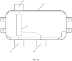
- FIG. 1a is a schematic structural diagram of a high-voltage distribution box having an open circuit trigger according to an embodiment of the present disclosure.
- the high-voltage distribution box having an open circuit trigger shown therein includes a distribution box housing 101, a first high-voltage connector 102, a second high-voltage connector 103, a low-voltage connector 104, and an open circuit trigger 111.
- the first high-voltage connector 102, the second high-voltage connector 103, and the low-voltage connector 104 are provided on a surface of the distribution box housing 101, and the open circuit trigger 111 is provided inside the distribution box housing 101.
- the first high-voltage connector 102 and the second high-voltage connector 103 are connected to a high-voltage loop of an electric vehicle (for example, an electric automobile, where electric vehicles in the embodiments described below are all referred to as electric automobiles, but it does not exclude that other electric vehicles also use the structure of the present disclosure as a high-voltage distribution box), and the first high-voltage connector 102 and the second high-voltage connector 103 are connected in series via the open circuit trigger 111.
- an electric vehicle for example, an electric automobile, where electric vehicles in the embodiments described below are all referred to as electric automobiles, but it does not exclude that other electric vehicles also use the structure of the present disclosure as a high-voltage distribution box
- the low-voltage connector 104 is connected to a control line of the electric automobile and configured to send an initiation control signal to the open circuit trigger 111 at a moment of collision.
- a high-voltage battery of the electric automobile is connected to a high-voltage appliance (for example, a motor) of an electric automobile via the high-voltage distribution box as shown in FIG. 1a , where a current output terminal of the high-voltage battery is connected to the first high-voltage connector 102, and a power supply wire of the high-voltage appliance is connected to the second high-voltage connector 103.
- a high-voltage appliance for example, a motor
- a control system of the electric automobile sends an initiation control signal to the open circuit trigger 111 via a control line of the electric automobile.
- the low-voltage connector 104 is connected to the control line of the electric automobile and sends the initiation control signal to the open circuit trigger 111.
- the open circuit trigger 111 immediately disconnects the series connection of the first high-voltage connector 102 and the second high-voltage connector 103, thus disconnecting the high-voltage battery of the electric automobile from the high-voltage appliance, so that the high-voltage loop of the electric automobile is powered down.
- the high-voltage distribution box having the open circuit trigger of the embodiments of the present disclosure when the electric automobile experiences a collision, the high-voltage loop of the electric automobile is disconnected immediately to power down the high-voltage system of the entire vehicle, reducing economic loss due to the collision of the electric automobile and human casualties.
- the current output terminal of the high-voltage battery may be also connected to the second high-voltage connector 103, and the power supply wire of the high-voltage appliance is connected to the first high-voltage connector 102. It is easy for those of ordinary skills to think of the operation process of the high-voltage distribution box with such connection method based on content of the foregoing embodiments, and details are not repeated in the embodiments of this specification.
- the first high-voltage connector 102 includes a first positive electricity connection terminal 107 and a first negative electricity connection terminal 108
- the second high-voltage connector 103 includes a second positive electricity connection terminal 109 and a second negative electricity connection terminal 110
- the open circuit trigger 111 further includes a main positive open circuit trigger 105 and a main negative open circuit trigger 106.
- the main positive open circuit trigger 105 is connected in series between the first positive electricity connection terminal 107 and the second positive electricity connection terminal 109, and the main negative open circuit trigger 106 is connected in series between the first negative electricity connection terminal 108 and the second negative electricity connection terminal 110.
- a positive electrode of the high-voltage battery is connected to the first positive electricity connection terminal 107
- a negative electrode of the high-voltage battery is connected to the first negative electricity connection terminal 108
- the second positive electricity connection terminal 109 is connected to a positive electrode of the high-voltage appliance
- the second negative electricity connection terminal 110 is connected to a negative electrode of the high-voltage appliance.
- the positive electrode of the high-voltage battery outputs a current of a positive loop to the first positive electricity connection terminal 107, the current sequentially passing through the open circuit trigger 111 and the second positive electricity connection terminal 109 to arrive at the positive electrode of the high-voltage appliance, and then the high-voltage appliance outputs a current of a negative loop to the second negative electricity connection terminal 110, the current sequentially passing through the open circuit trigger 111 and the first negative electricity connection terminal 108 to arrive at the negative electrode of the high-voltage battery.
- the control system of the electric automobile sends an initiation control signal to both of the main positive open circuit trigger 105 and the main negative open circuit trigger 106 via the control line of the electric automobile.
- the low-voltage connector 104 is connected to the control line of the electric automobile and sends the initiation control signal to both of the main positive open circuit trigger 105 and the main negative open circuit trigger 106.
- the main positive open circuit trigger 105 Upon receipt of the initiation control signal, the main positive open circuit trigger 105 immediately disconnects the series connection of the first positive electricity connection terminal 107 and the second positive electricity connection terminal 109.
- the main negative open circuit trigger 106 Upon receipt of the initiation control signal, the main negative open circuit trigger 106 immediately disconnects the series connection of the first negative electricity connection terminal 108 and the second negative electricity connection terminal 110, thus disconnecting the positive electrode of the high-voltage battery from the positive electrode of the high-voltage appliance and disconnecting the negative electrode of the high-voltage battery from the negative electrode of the high-voltage appliance, so that the positive and negative high-voltage loops of the electric automobile are powered down.
- the open circuit trigger 111 further includes a connecting pin 301 and a trigger 302, and the connecting pin 301 is movably connected between a first end 306 of the open circuit trigger and a second end 307 thereof.
- the trigger 302 is provided at an end of the connecting pin 301 and connected to the low-voltage connector 104 and receives the initiation control signal.
- the first end 306 of the open circuit trigger is connected to the first high-voltage connector 102
- the second end 307 of the open circuit trigger is connected to the second high-voltage connector 103.
- the trigger 302 receives the initiation control signal, enabling the connecting pin 301 to disconnect the connection between the first end 306 of the open circuit trigger and the second end 307 of the open circuit trigger, thus disconnecting the series connection of the first high-voltage connector 102 and the second high-voltage connector 103, so that the high-voltage of the entire vehicle is powered down.
- the trigger 302 further includes a trigger resistor 303 and an expansion component 304, the trigger resistor 303 is connected to the low-voltage connector 104, and the expansion component 304 is provided at an end of the connecting pin 301.
- the trigger resistor 303 is configured to, upon receipt of the initiation control signal, control the expansion component 304 to swell and deform to enable the connecting pin 301 to disconnect the connection between the first end 306 of the open circuit trigger and the second end 307 of the open circuit trigger.
- the expansion component 304 may be an explosive or a gas generator.
- the expansion component 304 described in the embodiments of the present disclosure is an explosive.
- the trigger resistor 303 rapidly heats up and ignites the explosive to enable the explosive to blast the connecting pin 301, so as to disconnect the connection between the first end 306 of the open circuit trigger and the second end 307 of the open circuit trigger.
- the expansion component 304 is a gas generator
- the trigger resistor 303 upon receipt of the initiation control signal, the trigger resistor 303 rapidly heats up and causes the gas generator to swell and deform to enable the connecting pin 301 to disconnect the connection between the first end 306 of the open circuit trigger and the second end 307 of the open circuit trigger.
- the expansion component may be another structure, which is not limited in the embodiments of this specification.
- the open circuit trigger 111 may further include an open circuit trigger control wire 305 connected in series between the trigger resistor 303 and the first low-voltage connector 104 and configured to transmit the initiation control signal to the trigger resistor 303.
- the distribution box housing 101 further includes a distribution-box lower housing 201 and a distribution-box upper cover 202.
- the distribution-box lower housing 201 may be connected to the distribution-box upper cover 202 through a bolt.
- the open circuit trigger 111 shown in FIG. 1a or FIG. 1b is provided inside an enclosed space formed by the distribution-box lower housing 201 and the distribution-box upper cover 202.
- the distribution-box lower housing 201 may be further connected to the distribution-box upper cover 202 in another connection manner, which is not limited in the embodiments of this specification.
- the high-voltage distribution box further includes a high-voltage repeater 215 provided inside an enclosed space formed by the distribution-box lower housing 201 and the distribution-box upper cover 202.
- the high-voltage repeater 215 and the main positive open circuit trigger 206 are connected in series between the first high-voltage connector 203 and the second high-voltage connector 204.
- the low-voltage connector 205 is further configured to, in a normal operation state, receive a control signal sent to the high-voltage repeater 215.
- connection order of the first high-voltage connector 203, the second high-voltage connector 204, the high-voltage repeater 215, and the open circuit trigger may be from the first high-voltage connector 203 to the main positive open circuit trigger 206, the high-voltage repeater 215, and then to the second high-voltage connector 204.
- the order of the high-voltage repeater 215 and the open circuit trigger may be exchanged.
- a high-voltage battery electronic control unit (ECU) of the electric automobile sends, based on an operation situation of the electric automobile, a control signal to the high-voltage repeater 215 via the control line of the electric automobile.
- the low-voltage connector 205 is connected to the control line of the electric automobile and sends the control signal of the high-voltage repeater 215 to the high-voltage repeater 215.
- the high-voltage repeater 215 disconnects the series connection of the first high-voltage connector 203 and the second high-voltage connector 204, thus disconnecting the high-voltage battery of the electric automobile from the high-voltage appliance.
- the open circuit trigger 111 further includes a main positive open circuit trigger 206 and a main negative open circuit trigger 207.
- the high-voltage repeater 215 and the main positive open circuit trigger 206 are connected in series between the first positive electricity connection terminal 211 of the first high-voltage connector 203 and the second positive electricity connection terminal 213 of the second high-voltage connector 204. After receiving the control signal, the high-voltage repeater 215 disconnects the series connection of the first positive electricity connection terminal 211 and the second positive electricity connection terminal 213, thus disconnecting the positive high-voltage loop of the electric automobile.
- the high-voltage distribution box may include a plurality of second high-voltage connectors 204, each second high-voltage connector 204 being connected to a different high-voltage appliance.
- the high-voltage distribution box may include a plurality of high-voltage repeaters 215, and the high-voltage repeaters 215 are in one-to-one correspondence to the second high-voltage connectors 204.
- the high-voltage battery ECU of the electric automobile can control each high-voltage repeater 215, so as to control power supply or power cut-off of different high-voltage appliances.
- the high-voltage distribution box may further include a high-voltage repeater control wire 216, and the high-voltage repeater control wire 216 has one end connected to the high-voltage repeater 215 and the other end connected to the low-voltage connector 205, for transmitting the control signal of the high-voltage repeater 215 from the low-voltage connector 205 to the high-voltage repeater 215.
- the high-voltage distribution box may further include a high-voltage circuit breaker 217 provided inside an enclosed space formed by the distribution-box lower housing 201 and the distribution-box upper cover 202.
- the high-voltage circuit breaker 217 and the main positive open circuit trigger 206 are connected in series between the first high-voltage connector 203 and the second high-voltage connector 204.
- the high-voltage circuit breaker 217 is configured to disconnect the series connection of the first high-voltage connector 203 and the second high-voltage connector 204 in a case of a short circuit in the high-voltage loop of the electric automobile or an excess load of the electric automobile.
- the first high-voltage connector 203, the second high-voltage connector 204, the high-voltage circuit breaker 217, and the main positive open circuit trigger 206 are connected in the same order of the high-voltage repeater 215 of the embodiments of the present disclosure, and thus details are not described in the embodiments of the present disclosure.
- the high-voltage circuit breaker 217 disconnects the series connection of the first high-voltage connector 203 and the second high-voltage connector 204, thus disconnecting the high-voltage loop and protecting the high-voltage loop of the electric automobile.
- the open circuit trigger 111 includes a main positive open circuit trigger 206 and a main negative open circuit trigger 207.
- the high-voltage circuit breaker 217 and the main positive open circuit trigger 206 are connected in series between the first positive electricity connection terminal 211 of the first high-voltage connector 203 and the second positive electricity connection terminal 213 of the second high-voltage connector 204.
- the high-voltage circuit breaker 217 disconnects the series connection of the first positive electricity connection terminal 211 and the second positive electricity connection terminal 213, thus disconnecting the positive high-voltage loop of the electric automobile.
- the high-voltage distribution box may include a plurality of high-voltage circuit breakers 217, and the high-voltage circuit breakers 217 are in one-to-one correspondence to the second high-voltage connectors 204, such that when one high-voltage appliance is prone to a short circuit or has an excess load, the series connection of the second high-voltage connector 204 connected to the high-voltage appliance and the first high-voltage connector 203 is disconnected separately, thus ensuring the normal operation of the other high-voltage appliances that have not been prone to a short circuit or an excess load.
- the high-voltage distribution box may further include a copper busbar (a main positive copper busbar 209 and a main negative copper busbar 210) and an insulation fixing block 219.
- the main positive copper busbar 209, the main negative copper busbar 210, and the insulation fixing block 219 are provided in an enclosed space formed by the distribution-box lower housing 201 and the distribution-box upper cover 202.
- the main positive copper busbar 209 and the main positive open circuit trigger 206 are connected in series between the first high-voltage connector 203 and the second high-voltage connector 204 (the main negative copper busbar 210 and the main negative open circuit trigger 207 are connected in series between the first high-voltage connector 203 and the second high-voltage connector 204), to conduct a high-voltage current between the first high-voltage connector 203 and the second high-voltage connector 204 inside the distribution box housing.
- the insulation fixing block 219 wraps the main positive copper busbar 209 or the main negative copper busbar 210, to fix the copper busbar inside the distribution box housing.
- the insulation fixing block 219 wraps the main positive copper busbar 209 or the main negative copper busbar 210 and fixes the main positive copper busbar 209 and the main negative copper busbar 210 inside the distribution box housing.
- the high-voltage distribution box may include a plurality of main positive copper busbars 209, main negative copper busbars 210, and insulation fixing blocks 219.
- Each copper busbar is connected to the open circuit trigger, the first high-voltage connector 203, and the second high-voltage connector 204 in series.
- Fixing bolts 218 may be used to connect the main positive copper busbar 209 to the main positive open circuit trigger, and may be used to connect the main negative copper busbar 210 to the second high-voltage connector 204 or both of the main negative open circuit trigger 207 and the first high-voltage connector 203.
- the open circuit trigger 111 further includes the main positive open circuit trigger 206 and the main negative open circuit trigger 207.
- the copper busbar further includes a main positive copper busbar 209 and a main negative copper busbar 210.
- the main positive copper busbar 209 and the main positive open circuit trigger 206 are connected in series between the first positive electricity connection terminal 211 of the first high-voltage connector 203 and the second positive electricity connection terminal 213 of the second high-voltage connector 204, and the main negative copper busbar 210 and the main negative open circuit trigger 207 are connected in series between the first negative electricity connection terminal 212 of the first high-voltage connector 203 and the second negative electricity connection terminal 214 of the second high-voltage connector 204.
- the main positive copper busbar 209 conducts a positive high-voltage current between the first positive electricity connection terminal 211 and the second positive electricity connection terminal 213 inside the distribution box housing
- the main negative copper busbar 210 conducts a negative high-voltage current between the first negative electricity connection terminal 212 and the second negative electricity connection terminal 214 inside the distribution box housing.
- the high-voltage distribution box may further include a high-voltage repeater 215, a high-voltage circuit breaker 217, a copper busbar, and an insulation fixing block 219.
- the high-voltage repeater 215, the high-voltage circuit breaker 217, the copper busbar, and the insulation fixing block 219 are provided in the enclosed space formed by the distribution-box lower housing 201 and the distribution-box upper cover 202.
- the high-voltage repeater 215, the high-voltage circuit breaker 217, the copper busbar, and the open circuit trigger 111 are connected in series between the first high-voltage connector 203 and the second high-voltage connector 204.
- the series connection order of the high-voltage repeater 215, the high-voltage circuit breaker 217, and the open circuit trigger 111 is not limited in the present disclosure.
- the open circuit trigger 111 further includes a main positive open circuit trigger 206 and a main negative open circuit trigger 207.
- the high-voltage repeater 215, the high-voltage circuit breaker 217, the main positive copper busbar 209, and the main positive open circuit trigger 206 are connected in series between the first positive electricity connection terminal 211 of the first high-voltage connector 203 and the second positive electricity connection terminal 213 of the second high-voltage connector 204, and the main negative copper busbar 210 and the main negative open circuit trigger 207 are connected between the first negative electricity connection terminal 212 of the first high-voltage connector 203 and the second negative electricity connection terminal 214 of the second high-voltage connector 204.
- the high-voltage battery ECU of the electric automobile sends, based on the operation situation of the electric automobile, a control signal to the high-voltage repeater 215 via the control line of the electric automobile.
- the low-voltage connector 205 is connected to the control line of the electric automobile and sends the control signal of the high-voltage repeater 215 to the high-voltage repeater 215.
- the high-voltage repeater 215 disconnects the series connection of the first positive electricity connection terminal 211 and the second positive electricity connection terminal 213, thus disconnecting the connection between the positive electrode of the high-voltage battery of the electric automobile and the positive electrode of the high-voltage appliance.
- the high-voltage circuit breaker 217 disconnects the series connection of the first positive electricity connection terminal 211 and the second positive electricity connection terminal 213, thus disconnecting the positive high-voltage loop.
- the open circuit trigger immediately disconnects the positive high-voltage loop of the electric automobile and the negative high-voltage loop of the electric automobile, so that the high-voltage of the entire vehicle is powered down, reducing economic loss due to the collision of the electric automobile and human casualties.
- FIG. 4 is a schematic structural diagram of a collision initiation system according to an embodiment of the present disclosure.
- the structure of the collision initiation system described in this figure includes a high-voltage distribution box 405 provided by the embodiments of the present disclosure, an airbag ECU 402, a collision sensor 403, and an airbag initiator 404.
- the airbag ECU 402 is connected to the low-voltage connector of the high-voltage distribution box 405, and the collision sensor 403 and the airbag initiator 404 are respectively connected to the airbag ECU 402.
- the airbag ECU 402 is configured to, after determining a collision status of the electric automobile based on a signal of the collision sensor 403 and a signal of the airbag initiator 404, send the initiation control signal to the low-voltage connector of the high-voltage distribution box 405.
- the collision sensor 403 collects a collision signal and sends the collision signal to the airbag ECU 402.
- the airbag ECU 402 judges whether a collision occurs. If the collision occurs, an initiation control signal is sent to the open circuit trigger 407 of the high-voltage distribution box 405 via the control line of the electric automobile.
- the low-voltage connector of the high-voltage distribution box 405 is connected to the control line of the electric automobile and sends the initiation control signal to the open circuit trigger 407 of the high-voltage distribution box 405.
- the open circuit trigger 407 immediately disconnects the high-voltage battery 401 of the electric automobile from the high-voltage appliance 406, so that the high-voltage loop of the electric automobile is powered down.
- the airbag initiator 404 quickly initiates the airbag of the automobile to reduce harm to passengers on the automobile.
- the airbag ECU 402 may further acquire the initiation status of the airbag initiator 404.
- an initiation control signal is sent to the open circuit trigger 407 of the high-voltage distribution box 405 via the control line of the electric automobile.
- the open circuit trigger 407 immediately disconnects the high-voltage battery 401 of the electric automobile from the high-voltage appliance 406, so that the high-voltage loop of the electric automobile is powered down.
- the airbag ECU 402 can determine the collision status of the collision sensor 403 and the initiation status of the airbag initiator 404 according to the method in the prior art, and details are not described in this specification.
- the collision sensor 403 further includes a left front collision sensor 408, a right front collision sensor 409, a left side collision sensor 410, a right side collision sensor 411, and a forward collision sensor 412, all of which are respectively mounted at different positions of the electric automobile as shown in FIG. 5 , and configured to detect collision of the electric automobile in all directions to facilitate the airbag ECU 402 to control the initiation of the open circuit trigger 407 of the high-voltage distribution box 405, so that the high-voltage system of the entire vehicle is powered down.
- the airbag initiator 404 further includes a driver airbag initiator 413, a driver side airbag initiator 414, a passenger airbag initiator 415, and a passenger side airbag initiator 416, all of which are respectively mounted at different positions of the electric automobile as shown in FIG. 5 and configured to detect the initiation status of the airbag of the electric automobile in all directions to facilitate the airbag ECU 402 to control the initiation of the open circuit trigger 407 of the high-voltage distribution box 405, so that the high-voltage system of the entire vehicle is powered down.
- driver airbag initiator 413, the driver side airbag initiator 414, the passenger airbag initiator 415, and the passenger side airbag initiator 416 in the embodiments of the present disclosure may be mounted based on hardware configurations of different car models or the needs of the vehicle owners.
- FIG. 5 is a schematic structural diagram of an electric automobile according to an embodiment of the present disclosure.
- the structure of the electric automobile described in this figure includes the collision initiation system provided by the embodiments of the present disclosure, an automobile body 512, and a high-voltage battery 509.
- the high-voltage battery 509 and the collision initiation system are provided inside the automobile body 512.
- the high-voltage distribution box 511 having an open circuit trigger is connected to the high-voltage battery 509 and configured to control the high-voltage battery 509 to supply power to a high-voltage appliance of the automobile body 512.
- the airbag ECU 510 sends an initiation control signal to the open circuit trigger of the high-voltage distribution box 511 based on a signal of the right front collision sensor 501, a signal of the left front collision sensor 502, a signal of the right side collision sensor 503, a signal of the left side collision sensor 504, a signal of the passenger airbag initiator 505, a signal of the driver airbag initiator 506, a signal of the passenger side airbag initiator 507, and a signal of the driver side airbag initiator 508.
- the open circuit trigger After receiving the initiation control signal, the open circuit trigger immediately disconnects the high-voltage loop of the entire vehicle.
- the mounting positions of the right front collision sensor 501, the left front collision sensor 502, the right side collision sensor 503, the left side collision sensor 504, the passenger airbag initiator 505, the driver airbag initiator 506, the passenger side airbag initiator 507, and the driver side airbag initiator 508 may be shown in FIG. 5 .
- the right front collision sensor 501 is configured to detect collision of the right front side of the automobile body 512
- the left front collision sensor 502 is configured to detect collision of the left front side of the automobile body 512
- the right side collision sensor 503 is configured to detect collision of the right side of the automobile body 512
- the left side collision sensor 504 is configured to detect collision of the left side of the automobile body 512.
- the passenger airbag initiator 505 is configured to detect initiation of the passenger airbag of the automobile body 512
- the driver airbag initiator 506 is configured to detect initiation of the driver airbag of the automobile body 512
- the passenger side airbag initiator 507 is configured to detect initiation of the passenger side airbag of the automobile body 512
- the driver side airbag initiator 508 is configured to detect initiation of the driver side airbag of the automobile body 512.
- sequence numbers of processes in various embodiments of the present disclosure do not mean execution sequences.
- the execution sequences of the processes should be determined based on functions and internal logic of the processes, and should not be construed as any limitation on implementation processes of the embodiments of the present disclosure.
Landscapes
- Engineering & Computer Science (AREA)
- Mechanical Engineering (AREA)
- Power Engineering (AREA)
- Life Sciences & Earth Sciences (AREA)
- Sustainable Development (AREA)
- Sustainable Energy (AREA)
- Transportation (AREA)
- Air Bags (AREA)
- Details Of Connecting Devices For Male And Female Coupling (AREA)
- Electric Propulsion And Braking For Vehicles (AREA)
- Connector Housings Or Holding Contact Members (AREA)
Abstract
Description
- The present disclosure claims priority to
Chinese Patent Application No. 202122718858.X, filed on November 8, 2021 - The present disclosure relates to the field of electric vehicles, and in particular to a high-voltage distribution box having an open circuit trigger, a collision initiation system, and an electric vehicle.
- With the rapid development of the new energy industry, the number of electric vehicles is also increasing continuously. Massive electric vehicles meanwhile pose a huge safety hazard. The most critical is to timely disconnect the high-voltage loop of the electric vehicle when it experiences a collision, thus ensuring the safety both of the occupants and peripheral ambulance personnel.
- The current measure being taken is that, upon collision, the airbag module sends out a power-off signal, which drives the relevant modules through a network or a hard wire to disconnect the main positive relay and main negative relay of the electric vehicle, so that the high-voltage system of the entire vehicle is powered down. If a relevant module, a circuit, or an actuator fails, the high-voltage loop of the electric vehicle cannot be disconnected in time, leading to injury or fatality caused by electric shock.
- How to promptly disconnect the high-voltage loop of the entire vehicle after a collision of the electric vehicle is a problem to be resolved urgently in the prior art.
- An objective of the present disclosure is to provide a high-voltage distribution box having an open circuit trigger, a collision initiation system, and an electric vehicle, such that when the electric vehicle experiences a collision, the high-voltage loop of the entire vehicle is disconnected immediately to reduce human casualties.
- The foregoing objective of the present disclosure can be achieved using the following technical solution:
An embodiment of the present disclosure provides a high-voltage distribution box having an open circuit trigger, including:
a distribution box housing, a first high-voltage connector, a second high-voltage connector, a low-voltage connector, and an open circuit trigger. - The first high-voltage connector, the second high-voltage connector, and the low-voltage connector are provided on a surface of the distribution box housing, and the open circuit trigger is provided inside the distribution box housing.
- The first high-voltage connector and the second high-voltage connector are connected to a high-voltage loop of an electric automobile, and the first high-voltage connector and the second high-voltage connector are connected in series via the open circuit trigger.
- The low-voltage connector is connected to a control line of the electric automobile and configured to send an initiation control signal to the open circuit trigger at a moment of collision.
- According to another aspect of the embodiments of the present disclosure, the first high-voltage connector includes a first positive electricity connection terminal and a first negative electricity connection terminal, the second high-voltage connector includes a second positive electricity connection terminal and a second negative electricity connection terminal, and the open circuit trigger further includes a main positive open circuit trigger and a main negative open circuit trigger.
- The main positive open circuit trigger is connected in series between the first positive electricity connection terminal and the second positive electricity connection terminal, and the main negative open circuit trigger is connected in series between the first negative electricity connection terminal and the second negative electricity connection terminal.
- According to another aspect of the embodiments of the present disclosure, the open circuit trigger further includes a connecting pin and a trigger, and the connecting pin is movably connected between a first end of the open circuit trigger and a second end thereof.
- The trigger is provided at an end of the connecting pin and connected to the low-voltage connector and receives the initiation control signal.
- According to another aspect of the embodiments of the present disclosure, the trigger further includes a trigger resistor and an expansion component, the trigger resistor is connected to the low-voltage connector, and the expansion component is provided at an end of the connecting pin.
- The trigger resistor is configured to, upon receipt of the initiation control signal, control the expansion component to swell and deform to enable the connecting pin to disconnect the connection between the first end of the open circuit trigger and the second end of the open circuit trigger.
- According to another aspect of the embodiments of the present disclosure, the expansion component is an explosive.
- According to another aspect of the embodiments of the present disclosure, the high-voltage distribution box further includes a high-voltage repeater, and the high-voltage repeater is provided inside the distribution box housing.
- The high-voltage repeater and the open circuit trigger are connected in series between the first high-voltage connector and the second high-voltage connector.
- The low-voltage connector is further configured to, in a normal operation state, receive a control signal sent to the high-voltage repeater.
- According to another aspect of the embodiments of the present disclosure, the high-voltage distribution box of the electric automobile further includes a high-voltage circuit breaker and the high-voltage circuit breaker is provided inside the distribution box housing.
- The high-voltage open circuit trigger and the open circuit trigger are connected in series between the first high-voltage connector and the second high-voltage connector.
- The high-voltage open circuit trigger is configured to disconnect the series connection of the first high-voltage connector and the second high-voltage connector in a case of a short circuit in the high-voltage loop of the electric automobile or an excess load of the electric automobile.
- According to another aspect of the embodiments of the present disclosure, the high-voltage distribution box of the electric automobile further includes a copper busbar and an insulation fixing block, and the copper busbar and the insulation fixing block are provided inside the distribution box housing.
- The copper busbar and the open circuit trigger are connected in series between the first high-voltage connector and the second high-voltage connector, to conduct a high-voltage current between the first high-voltage connector and the second high-voltage connector inside the distribution box housing.
- The insulation fixing block wraps the copper busbar and is configured to fix the copper busbar inside the distribution box housing.
- The embodiments of the present disclosure further include a collision initiation system, including the high-voltage distribution box having an open circuit trigger provided by the embodiments of the present disclosure, an airbag ECU (Electronic Control Unit), a collision sensor, and an airbag initiator.
- The airbag ECU is connected to the low-voltage connector of the high-voltage distribution box having the open circuit trigger, and the collision sensor and the airbag initiator are respectively connected to the airbag ECU.
- The airbag ECU is configured to, after determining a collision status of the electric automobile based on a signal of the collision sensor and a signal of the airbag initiator, send the initiation control signal to the low-voltage connector of the high-voltage distribution box having the open circuit trigger.
- The embodiments of the present disclosure further provide the collision initiation system provided by the embodiments of the present disclosure, an electric automobile, including an automobile body, and a high-voltage battery.
- The high-voltage battery and the collision initiation system are provided in the automobile body.
- The high-voltage distribution box having the open circuit trigger is connected to the high-voltage battery and configured to control the high-voltage battery to supply power to a high-voltage appliance of the automobile body.
- According to the embodiments of the present disclosure, when the electric vehicle experiences a collision, the control line of the electric vehicle sends an initiation control signal for initiating the open circuit trigger to the low-voltage connector. Upon receipt of the initiation control signal, the open circuit trigger immediately disconnects the series connection of the first high-voltage connector and the second high-voltage connector in the high-voltage distribution box, so as to disconnect the high-voltage loop of the electric vehicle which is connected to both of the first high-voltage connector and the second high-voltage connector, so that the high-voltage system of the entire vehicle is powered down, thereby reducing economic loss due to the collision of the electric vehicle and human casualties.
- To describe the technical solutions in the embodiments of the present disclosure and the prior art more clearly, the drawings to be used in the description of the embodiments or the prior art will be briefly described below. Obviously, the drawings in the following description show only some embodiments of the present disclosure, and persons of ordinary skill in the art may still obtain other drawings from these drawings without inventive efforts.
-
FIG. 1a is a schematic structural diagram of a high-voltage distribution box having an open circuit trigger according to an embodiment of the present disclosure. -
FIG. 1b is a schematic structural diagram of a high-voltage distribution box having an open circuit trigger according to an embodiment of the present disclosure. -
FIG. 2 is a specific structural diagram of a high-voltage distribution box having an open circuit trigger according to an embodiment of the present disclosure. -
FIG. 3 is a schematic structural diagram of an open circuit trigger according to an embodiment of the present disclosure. -
FIG. 4 is a schematic structural diagram of a collision initiation system according to an embodiment of the present disclosure. -
FIG. 5 is a schematic structural diagram of an electric automobile according to an embodiment of the present disclosure. -
- 101. distribution box housing
- 102. first high-voltage connector
- 103. second high-voltage connector
- 104. low-voltage connector
- 105. main positive open circuit trigger
- 106. main negative open circuit trigger
- 107. first positive electricity connection terminal
- 108. first negative electricity connection terminal
- 109. second positive electricity connection terminal
- 110. second negative electricity connection terminal
- 111. open circuit trigger
- 201. distribution-box lower housing
- 202. distribution-box upper cover
- 203. first high-voltage connector
- 204. second high-voltage connector
- 205. low-voltage connector
- 206. main positive open circuit trigger
- 207. main negative open circuit trigger
- 208. open circuit trigger control wire
- 209. main positive copper busbar
- 210. main negative copper busbar
- 211. first positive electricity connection terminal
- 212. first negative electricity connection terminal
- 213. second positive electricity connection terminal
- 214. second negative electricity connection terminal
- 215. high-voltage repeater
- 216. high-voltage repeater control wire
- 217. high-voltage circuit breaker
- 218. fixing bolt
- 219. insulation fixing block
- 301. connecting pin
- 302. trigger
- 303. trigger resistor
- 304. expansion component
- 305. open circuit trigger control wire
- 306. first end of the open circuit trigger
- 307. second end of the open circuit trigger
- 401. high-voltage battery
- 402. airbag ECU
- 403. collision sensor
- 404. airbag initiator
- 405. high-voltage distribution box
- 406. high-voltage appliance
- 407. open circuit trigger
- 408. left front collision sensor
- 409. right front collision sensor
- 410. left side collision sensor
- 411. right side collision sensor
- 412. forward collision sensor
- 413. driver airbag initiator
- 414. driver side airbag initiator
- 415. passenger airbag initiator
- 416. passenger side airbag initiator
- 501. right front collision sensor
- 502. left front collision sensor
- 503. right side collision sensor
- 504. left side collision sensor
- 505. passenger airbag initiator
- 506. driver airbag initiator
- 507. passenger side airbag initiator
- 508. driver side airbag initiator
- 509. high-voltage battery
- 510. airbag ECU
- 511. high-voltage distribution box
- 512. automobile body
- The following clearly and completely describes the technical solutions in the embodiments of the present disclosure with reference to the drawings in the embodiments of the present disclosure. Obviously, the described embodiments are only some rather than all of the embodiments of the present disclosure. All other embodiments obtained by persons of ordinary skill in the art based on the embodiments of the present disclosure without inventive efforts shall fall within the protection scope of the present disclosure.
-
FIG. 1a is a schematic structural diagram of a high-voltage distribution box having an open circuit trigger according to an embodiment of the present disclosure. The high-voltage distribution box having an open circuit trigger shown therein includes adistribution box housing 101, a first high-voltage connector 102, a second high-voltage connector 103, a low-voltage connector 104, and anopen circuit trigger 111. - The first high-
voltage connector 102, the second high-voltage connector 103, and the low-voltage connector 104 are provided on a surface of thedistribution box housing 101, and theopen circuit trigger 111 is provided inside thedistribution box housing 101. - The first high-
voltage connector 102 and the second high-voltage connector 103 are connected to a high-voltage loop of an electric vehicle (for example, an electric automobile, where electric vehicles in the embodiments described below are all referred to as electric automobiles, but it does not exclude that other electric vehicles also use the structure of the present disclosure as a high-voltage distribution box), and the first high-voltage connector 102 and the second high-voltage connector 103 are connected in series via theopen circuit trigger 111. - The low-
voltage connector 104 is connected to a control line of the electric automobile and configured to send an initiation control signal to theopen circuit trigger 111 at a moment of collision. - In the embodiments of the present disclosure, a high-voltage battery of the electric automobile is connected to a high-voltage appliance (for example, a motor) of an electric automobile via the high-voltage distribution box as shown in
FIG. 1a , where a current output terminal of the high-voltage battery is connected to the first high-voltage connector 102, and a power supply wire of the high-voltage appliance is connected to the second high-voltage connector 103. - During normal operation of the electric automobile, current of the high-voltage battery sequentially passes through the first high-
voltage connector 102, theopen circuit trigger 111, and the second high-voltage connector 103 to the high-voltage appliance. - When the electric automobile experiences a collision, a control system of the electric automobile sends an initiation control signal to the
open circuit trigger 111 via a control line of the electric automobile. The low-voltage connector 104 is connected to the control line of the electric automobile and sends the initiation control signal to theopen circuit trigger 111. After receiving the initiation control signal, theopen circuit trigger 111 immediately disconnects the series connection of the first high-voltage connector 102 and the second high-voltage connector 103, thus disconnecting the high-voltage battery of the electric automobile from the high-voltage appliance, so that the high-voltage loop of the electric automobile is powered down. - With the use of the high-voltage distribution box having the open circuit trigger of the embodiments of the present disclosure, when the electric automobile experiences a collision, the high-voltage loop of the electric automobile is disconnected immediately to power down the high-voltage system of the entire vehicle, reducing economic loss due to the collision of the electric automobile and human casualties.
- In addition, the current output terminal of the high-voltage battery may be also connected to the second high-
voltage connector 103, and the power supply wire of the high-voltage appliance is connected to the first high-voltage connector 102. It is easy for those of ordinary skills to think of the operation process of the high-voltage distribution box with such connection method based on content of the foregoing embodiments, and details are not repeated in the embodiments of this specification. - In an embodiment of the present disclosure, to further ensure the safety of the positive and negative high-voltage loops when the electric automobile experiences a collision, as shown in
FIG. 1b , the first high-voltage connector 102 includes a first positiveelectricity connection terminal 107 and a first negativeelectricity connection terminal 108, the second high-voltage connector 103 includes a second positive electricity connection terminal 109 and a second negative electricity connection terminal 110, and theopen circuit trigger 111 further includes a main positiveopen circuit trigger 105 and a main negativeopen circuit trigger 106. - The main positive
open circuit trigger 105 is connected in series between the first positiveelectricity connection terminal 107 and the second positive electricity connection terminal 109, and the main negativeopen circuit trigger 106 is connected in series between the first negativeelectricity connection terminal 108 and the second negative electricity connection terminal 110. - In the embodiments of the present disclosure, a positive electrode of the high-voltage battery is connected to the first positive
electricity connection terminal 107, a negative electrode of the high-voltage battery is connected to the first negativeelectricity connection terminal 108, the second positive electricity connection terminal 109 is connected to a positive electrode of the high-voltage appliance, and the second negative electricity connection terminal 110 is connected to a negative electrode of the high-voltage appliance. - During normal operation of the electric automobile, the positive electrode of the high-voltage battery outputs a current of a positive loop to the first positive
electricity connection terminal 107, the current sequentially passing through theopen circuit trigger 111 and the second positive electricity connection terminal 109 to arrive at the positive electrode of the high-voltage appliance, and then the high-voltage appliance outputs a current of a negative loop to the second negative electricity connection terminal 110, the current sequentially passing through theopen circuit trigger 111 and the first negativeelectricity connection terminal 108 to arrive at the negative electrode of the high-voltage battery. - In the embodiments of the present disclosure, during normal operation of the electric automobile, the positive electrode of the high-voltage battery outputs a current of a positive loop to the first positive
electricity connection terminal 107, the current sequentially passing through the main positiveopen circuit trigger 105 and the second positive electricity connection terminal 109 to arrive at the positive electrode of the high-voltage appliance, and then the high-voltage appliance outputs a current of a negative loop to the second negative electricity connection terminal 110, the current passing through the main negativeopen circuit trigger 106 and the first negativeelectricity connection terminal 108 to arrive at the negative electrode of the high-voltage battery. - When the electric automobile experiences a collision, the control system of the electric automobile sends an initiation control signal to both of the main positive
open circuit trigger 105 and the main negativeopen circuit trigger 106 via the control line of the electric automobile. The low-voltage connector 104 is connected to the control line of the electric automobile and sends the initiation control signal to both of the main positiveopen circuit trigger 105 and the main negativeopen circuit trigger 106. Upon receipt of the initiation control signal, the main positiveopen circuit trigger 105 immediately disconnects the series connection of the first positiveelectricity connection terminal 107 and the second positive electricity connection terminal 109. Upon receipt of the initiation control signal, the main negativeopen circuit trigger 106 immediately disconnects the series connection of the first negativeelectricity connection terminal 108 and the second negative electricity connection terminal 110, thus disconnecting the positive electrode of the high-voltage battery from the positive electrode of the high-voltage appliance and disconnecting the negative electrode of the high-voltage battery from the negative electrode of the high-voltage appliance, so that the positive and negative high-voltage loops of the electric automobile are powered down. - In an embodiment of the present disclosure, as shown in
FIG. 3 , theopen circuit trigger 111 further includes a connectingpin 301 and atrigger 302, and the connectingpin 301 is movably connected between afirst end 306 of the open circuit trigger and asecond end 307 thereof. - The
trigger 302 is provided at an end of the connectingpin 301 and connected to the low-voltage connector 104 and receives the initiation control signal. - In the embodiments of the present disclosure, the
first end 306 of the open circuit trigger is connected to the first high-voltage connector 102, and thesecond end 307 of the open circuit trigger is connected to the second high-voltage connector 103. When the electric automobile malfunctions, thetrigger 302 receives the initiation control signal, enabling the connectingpin 301 to disconnect the connection between thefirst end 306 of the open circuit trigger and thesecond end 307 of the open circuit trigger, thus disconnecting the series connection of the first high-voltage connector 102 and the second high-voltage connector 103, so that the high-voltage of the entire vehicle is powered down. - In an embodiment of the present disclosure, as shown in
FIG. 3 , thetrigger 302 further includes atrigger resistor 303 and anexpansion component 304, thetrigger resistor 303 is connected to the low-voltage connector 104, and theexpansion component 304 is provided at an end of the connectingpin 301. - The
trigger resistor 303 is configured to, upon receipt of the initiation control signal, control theexpansion component 304 to swell and deform to enable the connectingpin 301 to disconnect the connection between thefirst end 306 of the open circuit trigger and thesecond end 307 of the open circuit trigger. - In the embodiments of the present disclosure, the
expansion component 304 may be an explosive or a gas generator. Exemplarily, theexpansion component 304 described in the embodiments of the present disclosure is an explosive. When theexpansion component 304 is an explosive, after receiving the initiation control signal, thetrigger resistor 303 rapidly heats up and ignites the explosive to enable the explosive to blast the connectingpin 301, so as to disconnect the connection between thefirst end 306 of the open circuit trigger and thesecond end 307 of the open circuit trigger. When theexpansion component 304 is a gas generator, upon receipt of the initiation control signal, thetrigger resistor 303 rapidly heats up and causes the gas generator to swell and deform to enable the connectingpin 301 to disconnect the connection between thefirst end 306 of the open circuit trigger and thesecond end 307 of the open circuit trigger. In addition, the expansion component may be another structure, which is not limited in the embodiments of this specification. - In the embodiments of the present disclosure, as shown in
FIG. 3 , theopen circuit trigger 111 may further include an open circuittrigger control wire 305 connected in series between thetrigger resistor 303 and the first low-voltage connector 104 and configured to transmit the initiation control signal to thetrigger resistor 303. - In an embodiment of the present disclosure, as shown in
FIG. 2 , thedistribution box housing 101 further includes a distribution-boxlower housing 201 and a distribution-boxupper cover 202. The distribution-boxlower housing 201 may be connected to the distribution-boxupper cover 202 through a bolt. Theopen circuit trigger 111 shown inFIG. 1a orFIG. 1b is provided inside an enclosed space formed by the distribution-boxlower housing 201 and the distribution-boxupper cover 202. The distribution-boxlower housing 201 may be further connected to the distribution-boxupper cover 202 in another connection manner, which is not limited in the embodiments of this specification. - In an embodiment of the present disclosure, to control power supply or power cut-off of the high-voltage appliance using the high-voltage distribution box in the embodiments of the present disclosure when the electric automobile is in a normal operation state, as shown in
FIG. 2 , the high-voltage distribution box further includes a high-voltage repeater 215 provided inside an enclosed space formed by the distribution-boxlower housing 201 and the distribution-boxupper cover 202. - The high-
voltage repeater 215 and the main positiveopen circuit trigger 206 are connected in series between the first high-voltage connector 203 and the second high-voltage connector 204. - The low-
voltage connector 205 is further configured to, in a normal operation state, receive a control signal sent to the high-voltage repeater 215. - In the embodiments of the present disclosure, the connection order of the first high-
voltage connector 203, the second high-voltage connector 204, the high-voltage repeater 215, and the open circuit trigger may be from the first high-voltage connector 203 to the main positiveopen circuit trigger 206, the high-voltage repeater 215, and then to the second high-voltage connector 204. The order of the high-voltage repeater 215 and the open circuit trigger may be exchanged. - In a normal operation state, a high-voltage battery electronic control unit (ECU) of the electric automobile sends, based on an operation situation of the electric automobile, a control signal to the high-
voltage repeater 215 via the control line of the electric automobile. The low-voltage connector 205 is connected to the control line of the electric automobile and sends the control signal of the high-voltage repeater 215 to the high-voltage repeater 215. After receiving the control signal, the high-voltage repeater 215 disconnects the series connection of the first high-voltage connector 203 and the second high-voltage connector 204, thus disconnecting the high-voltage battery of the electric automobile from the high-voltage appliance. - As shown in
FIG. 2 , theopen circuit trigger 111 further includes a main positiveopen circuit trigger 206 and a main negative open circuit trigger 207. Exemplarily, the high-voltage repeater 215 and the main positiveopen circuit trigger 206 are connected in series between the first positiveelectricity connection terminal 211 of the first high-voltage connector 203 and the second positiveelectricity connection terminal 213 of the second high-voltage connector 204. After receiving the control signal, the high-voltage repeater 215 disconnects the series connection of the first positiveelectricity connection terminal 211 and the second positiveelectricity connection terminal 213, thus disconnecting the positive high-voltage loop of the electric automobile. - As shown in
FIG. 2 , the high-voltage distribution box may include a plurality of second high-voltage connectors 204, each second high-voltage connector 204 being connected to a different high-voltage appliance. In addition, based on the quantity of the second high-voltage connectors 204, the high-voltage distribution box may include a plurality of high-voltage repeaters 215, and the high-voltage repeaters 215 are in one-to-one correspondence to the second high-voltage connectors 204. The high-voltage battery ECU of the electric automobile can control each high-voltage repeater 215, so as to control power supply or power cut-off of different high-voltage appliances. - In an embodiment of the present disclosure, as shown in
FIG. 2 , the high-voltage distribution box may further include a high-voltagerepeater control wire 216, and the high-voltagerepeater control wire 216 has one end connected to the high-voltage repeater 215 and the other end connected to the low-voltage connector 205, for transmitting the control signal of the high-voltage repeater 215 from the low-voltage connector 205 to the high-voltage repeater 215. - In an embodiment of the present disclosure, when the high-voltage loop of the electric automobile experiences a short circuit or the high-voltage appliance has an excess load, to protect the high-voltage loop of the electric automobile using the high-voltage distribution box, as shown in
FIG. 2 , the high-voltage distribution box may further include a high-voltage circuit breaker 217 provided inside an enclosed space formed by the distribution-boxlower housing 201 and the distribution-boxupper cover 202. - The high-
voltage circuit breaker 217 and the main positiveopen circuit trigger 206 are connected in series between the first high-voltage connector 203 and the second high-voltage connector 204. - The high-
voltage circuit breaker 217 is configured to disconnect the series connection of the first high-voltage connector 203 and the second high-voltage connector 204 in a case of a short circuit in the high-voltage loop of the electric automobile or an excess load of the electric automobile. - In the embodiments of the present disclosure, the first high-
voltage connector 203, the second high-voltage connector 204, the high-voltage circuit breaker 217, and the main positiveopen circuit trigger 206 are connected in the same order of the high-voltage repeater 215 of the embodiments of the present disclosure, and thus details are not described in the embodiments of the present disclosure. - When the high-voltage loop of the electric automobile is prone to a short circuit or the high-voltage appliance has an excess load, the high-
voltage circuit breaker 217 disconnects the series connection of the first high-voltage connector 203 and the second high-voltage connector 204, thus disconnecting the high-voltage loop and protecting the high-voltage loop of the electric automobile. - As shown in
FIG. 2 , theopen circuit trigger 111 includes a main positiveopen circuit trigger 206 and a main negative open circuit trigger 207. Exemplarily, the high-voltage circuit breaker 217 and the main positiveopen circuit trigger 206 are connected in series between the first positiveelectricity connection terminal 211 of the first high-voltage connector 203 and the second positiveelectricity connection terminal 213 of the second high-voltage connector 204. When the high-voltage loop of the electric automobile is prone to a short circuit or the high-voltage appliance has an excess load, the high-voltage circuit breaker 217 disconnects the series connection of the first positiveelectricity connection terminal 211 and the second positiveelectricity connection terminal 213, thus disconnecting the positive high-voltage loop of the electric automobile. - As shown in
FIG. 2 , the high-voltage distribution box may include a plurality of high-voltage circuit breakers 217, and the high-voltage circuit breakers 217 are in one-to-one correspondence to the second high-voltage connectors 204, such that when one high-voltage appliance is prone to a short circuit or has an excess load, the series connection of the second high-voltage connector 204 connected to the high-voltage appliance and the first high-voltage connector 203 is disconnected separately, thus ensuring the normal operation of the other high-voltage appliances that have not been prone to a short circuit or an excess load. - In an embodiment of the present disclosure, to increase the maximum current conducted by the high-voltage distribution box, as shown in
FIG. 2 , the high-voltage distribution box may further include a copper busbar (a mainpositive copper busbar 209 and a main negative copper busbar 210) and aninsulation fixing block 219. The mainpositive copper busbar 209, the mainnegative copper busbar 210, and theinsulation fixing block 219 are provided in an enclosed space formed by the distribution-boxlower housing 201 and the distribution-boxupper cover 202. - The main
positive copper busbar 209 and the main positiveopen circuit trigger 206 are connected in series between the first high-voltage connector 203 and the second high-voltage connector 204 (the mainnegative copper busbar 210 and the main negative open circuit trigger 207 are connected in series between the first high-voltage connector 203 and the second high-voltage connector 204), to conduct a high-voltage current between the first high-voltage connector 203 and the second high-voltage connector 204 inside the distribution box housing. - The
insulation fixing block 219 wraps the mainpositive copper busbar 209 or the mainnegative copper busbar 210, to fix the copper busbar inside the distribution box housing. - In the embodiments of the present disclosure, due to a large cross-sectional area of the main
positive copper busbar 209 or the mainnegative copper busbar 210, a larger current can be conducted. In addition, the mainpositive copper busbar 209 or the mainnegative copper busbar 210 is exposed in the high-voltage distribution box, to prevent a plurality of mainpositive copper busbars 209 and/or mainnegative copper busbars 210 from causing a short circuit, theinsulation fixing block 219 wraps the mainpositive copper busbar 209 or the mainnegative copper busbar 210 and fixes the mainpositive copper busbar 209 and the mainnegative copper busbar 210 inside the distribution box housing. - As shown in
FIG. 2 , the high-voltage distribution box may include a plurality of mainpositive copper busbars 209, mainnegative copper busbars 210, and insulation fixing blocks 219. Each copper busbar is connected to the open circuit trigger, the first high-voltage connector 203, and the second high-voltage connector 204 in series. Fixingbolts 218 may be used to connect the mainpositive copper busbar 209 to the main positive open circuit trigger, and may be used to connect the mainnegative copper busbar 210 to the second high-voltage connector 204 or both of the main negative open circuit trigger 207 and the first high-voltage connector 203. - As shown in
FIG. 2 , theopen circuit trigger 111 further includes the main positiveopen circuit trigger 206 and the main negative open circuit trigger 207. Exemplarily, the copper busbar further includes a mainpositive copper busbar 209 and a mainnegative copper busbar 210. The mainpositive copper busbar 209 and the main positiveopen circuit trigger 206 are connected in series between the first positiveelectricity connection terminal 211 of the first high-voltage connector 203 and the second positiveelectricity connection terminal 213 of the second high-voltage connector 204, and the mainnegative copper busbar 210 and the main negative open circuit trigger 207 are connected in series between the first negativeelectricity connection terminal 212 of the first high-voltage connector 203 and the second negative electricity connection terminal 214 of the second high-voltage connector 204. The mainpositive copper busbar 209 conducts a positive high-voltage current between the first positiveelectricity connection terminal 211 and the second positiveelectricity connection terminal 213 inside the distribution box housing, and the mainnegative copper busbar 210 conducts a negative high-voltage current between the first negativeelectricity connection terminal 212 and the second negative electricity connection terminal 214 inside the distribution box housing. - In an embodiment of the present disclosure, as shown in
FIG. 2 , the high-voltage distribution box may further include a high-voltage repeater 215, a high-voltage circuit breaker 217, a copper busbar, and aninsulation fixing block 219. The high-voltage repeater 215, the high-voltage circuit breaker 217, the copper busbar, and theinsulation fixing block 219 are provided in the enclosed space formed by the distribution-boxlower housing 201 and the distribution-boxupper cover 202. - The high-
voltage repeater 215, the high-voltage circuit breaker 217, the copper busbar, and theopen circuit trigger 111 are connected in series between the first high-voltage connector 203 and the second high-voltage connector 204. - In the embodiments of the present disclosure, the series connection order of the high-
voltage repeater 215, the high-voltage circuit breaker 217, and theopen circuit trigger 111 is not limited in the present disclosure. - As shown in
FIG. 2 , theopen circuit trigger 111 further includes a main positiveopen circuit trigger 206 and a main negative open circuit trigger 207. Exemplarily, the high-voltage repeater 215, the high-voltage circuit breaker 217, the mainpositive copper busbar 209, and the main positiveopen circuit trigger 206 are connected in series between the first positiveelectricity connection terminal 211 of the first high-voltage connector 203 and the second positiveelectricity connection terminal 213 of the second high-voltage connector 204, and the mainnegative copper busbar 210 and the main negative open circuit trigger 207 are connected between the first negativeelectricity connection terminal 212 of the first high-voltage connector 203 and the second negative electricity connection terminal 214 of the second high-voltage connector 204. - In a normal operation state, the high-voltage battery ECU of the electric automobile sends, based on the operation situation of the electric automobile, a control signal to the high-
voltage repeater 215 via the control line of the electric automobile. The low-voltage connector 205 is connected to the control line of the electric automobile and sends the control signal of the high-voltage repeater 215 to the high-voltage repeater 215. After receiving the control signal, the high-voltage repeater 215 disconnects the series connection of the first positiveelectricity connection terminal 211 and the second positiveelectricity connection terminal 213, thus disconnecting the connection between the positive electrode of the high-voltage battery of the electric automobile and the positive electrode of the high-voltage appliance. - When the high-voltage loop of the electric automobile is prone to a short circuit or the high-voltage appliance has an excess load, the high-
voltage circuit breaker 217 disconnects the series connection of the first positiveelectricity connection terminal 211 and the second positiveelectricity connection terminal 213, thus disconnecting the positive high-voltage loop. - With the use of the high-voltage distribution box having an open circuit trigger of the embodiments of the present disclosure, when the electric automobile experiences a collision, the open circuit trigger immediately disconnects the positive high-voltage loop of the electric automobile and the negative high-voltage loop of the electric automobile, so that the high-voltage of the entire vehicle is powered down, reducing economic loss due to the collision of the electric automobile and human casualties.
-
FIG. 4 is a schematic structural diagram of a collision initiation system according to an embodiment of the present disclosure. The structure of the collision initiation system described in this figure includes a high-voltage distribution box 405 provided by the embodiments of the present disclosure, anairbag ECU 402, acollision sensor 403, and anairbag initiator 404. - The
airbag ECU 402 is connected to the low-voltage connector of the high-voltage distribution box 405, and thecollision sensor 403 and theairbag initiator 404 are respectively connected to theairbag ECU 402. - The
airbag ECU 402 is configured to, after determining a collision status of the electric automobile based on a signal of thecollision sensor 403 and a signal of theairbag initiator 404, send the initiation control signal to the low-voltage connector of the high-voltage distribution box 405. - In the embodiments of the present disclosure, when the electric automobile experiences a collision, the
collision sensor 403 collects a collision signal and sends the collision signal to theairbag ECU 402. Theairbag ECU 402 judges whether a collision occurs. If the collision occurs, an initiation control signal is sent to theopen circuit trigger 407 of the high-voltage distribution box 405 via the control line of the electric automobile. The low-voltage connector of the high-voltage distribution box 405 is connected to the control line of the electric automobile and sends the initiation control signal to theopen circuit trigger 407 of the high-voltage distribution box 405. After receiving the initiation control signal, theopen circuit trigger 407 immediately disconnects the high-voltage battery 401 of the electric automobile from the high-voltage appliance 406, so that the high-voltage loop of the electric automobile is powered down. - In addition, when the electric automobile experiences a collision, the
airbag initiator 404 quickly initiates the airbag of the automobile to reduce harm to passengers on the automobile. Theairbag ECU 402 may further acquire the initiation status of theairbag initiator 404. When theairbag ECU 402 obtains the information of initiation of theairbag initiator 404, an initiation control signal is sent to theopen circuit trigger 407 of the high-voltage distribution box 405 via the control line of the electric automobile. After receiving the initiation control signal, theopen circuit trigger 407 immediately disconnects the high-voltage battery 401 of the electric automobile from the high-voltage appliance 406, so that the high-voltage loop of the electric automobile is powered down. - In the embodiments of the present disclosure, the
airbag ECU 402 can determine the collision status of thecollision sensor 403 and the initiation status of theairbag initiator 404 according to the method in the prior art, and details are not described in this specification. - Exemplarily, as shown in
FIG. 4 , thecollision sensor 403 further includes a leftfront collision sensor 408, a rightfront collision sensor 409, a left side collision sensor 410, a rightside collision sensor 411, and aforward collision sensor 412, all of which are respectively mounted at different positions of the electric automobile as shown inFIG. 5 , and configured to detect collision of the electric automobile in all directions to facilitate theairbag ECU 402 to control the initiation of theopen circuit trigger 407 of the high-voltage distribution box 405, so that the high-voltage system of the entire vehicle is powered down. Theairbag initiator 404 further includes adriver airbag initiator 413, a driverside airbag initiator 414, apassenger airbag initiator 415, and a passengerside airbag initiator 416, all of which are respectively mounted at different positions of the electric automobile as shown inFIG. 5 and configured to detect the initiation status of the airbag of the electric automobile in all directions to facilitate theairbag ECU 402 to control the initiation of theopen circuit trigger 407 of the high-voltage distribution box 405, so that the high-voltage system of the entire vehicle is powered down. Thedriver airbag initiator 413, the driverside airbag initiator 414, thepassenger airbag initiator 415, and the passengerside airbag initiator 416 in the embodiments of the present disclosure may be mounted based on hardware configurations of different car models or the needs of the vehicle owners. -
FIG. 5 is a schematic structural diagram of an electric automobile according to an embodiment of the present disclosure. The structure of the electric automobile described in this figure includes the collision initiation system provided by the embodiments of the present disclosure, anautomobile body 512, and a high-voltage battery 509. - The high-
voltage battery 509 and the collision initiation system are provided inside theautomobile body 512. - The high-
voltage distribution box 511 having an open circuit trigger is connected to the high-voltage battery 509 and configured to control the high-voltage battery 509 to supply power to a high-voltage appliance of theautomobile body 512. - In the embodiments of the present disclosure, the
airbag ECU 510 sends an initiation control signal to the open circuit trigger of the high-voltage distribution box 511 based on a signal of the rightfront collision sensor 501, a signal of the leftfront collision sensor 502, a signal of the rightside collision sensor 503, a signal of the leftside collision sensor 504, a signal of thepassenger airbag initiator 505, a signal of thedriver airbag initiator 506, a signal of the passengerside airbag initiator 507, and a signal of the driverside airbag initiator 508. After receiving the initiation control signal, the open circuit trigger immediately disconnects the high-voltage loop of the entire vehicle. - The mounting positions of the right
front collision sensor 501, the leftfront collision sensor 502, the rightside collision sensor 503, the leftside collision sensor 504, thepassenger airbag initiator 505, thedriver airbag initiator 506, the passengerside airbag initiator 507, and the driverside airbag initiator 508 may be shown inFIG. 5 . The rightfront collision sensor 501 is configured to detect collision of the right front side of theautomobile body 512, the leftfront collision sensor 502 is configured to detect collision of the left front side of theautomobile body 512, the rightside collision sensor 503 is configured to detect collision of the right side of theautomobile body 512, and the leftside collision sensor 504 is configured to detect collision of the left side of theautomobile body 512. Thepassenger airbag initiator 505 is configured to detect initiation of the passenger airbag of theautomobile body 512, thedriver airbag initiator 506 is configured to detect initiation of the driver airbag of theautomobile body 512, the passengerside airbag initiator 507 is configured to detect initiation of the passenger side airbag of theautomobile body 512, and the driverside airbag initiator 508 is configured to detect initiation of the driver side airbag of theautomobile body 512. - It should be understood that sequence numbers of processes in various embodiments of the present disclosure do not mean execution sequences. The execution sequences of the processes should be determined based on functions and internal logic of the processes, and should not be construed as any limitation on implementation processes of the embodiments of the the present disclosure.
- The principle and the implementations of the present disclosure are described in this specification by using specific embodiments. The descriptions about the embodiments are merely provided to help understand the method and the core idea of the present disclosure. In addition, a person of ordinary skill in the art may make changes to the specific implementations and the application scope according to the idea of the present disclosure. Therefore, the content of this specification shall not be construed as a limitation on the present disclosure.
Claims (10)
- A high-voltage distribution box having an open circuit trigger, comprising:a distribution box housing, a first high-voltage connector, a second high-voltage connector, a low-voltage connector, and an open circuit trigger; whereinthe first high-voltage connector, the second high-voltage connector, and the low-voltage connector are provided on a surface of the distribution box housing, and the open circuit trigger is provided inside the distribution box housing;the first high-voltage connector and the second high-voltage connector are connected to a high-voltage loop of an electric automobile, and the first high-voltage connector and the second high-voltage connector are connected in series via the open circuit trigger; andthe low-voltage connector is connected to a control line of the electric automobile and configured to send an initiation control signal to the open circuit trigger at a moment of collision.
- The high-voltage distribution box having the open circuit trigger according to claim 1, wherein the first high-voltage connector comprises a first positive electricity connection terminal and a first negative electricity connection terminal, the second high-voltage connector comprises a second positive electricity connection terminal and a second negative electricity connection terminal, and the open circuit trigger further comprises a main positive open circuit trigger and a main negative open circuit trigger; wherein
the main positive open circuit trigger is connected in series between the first positive electricity connection terminal and the second positive electricity connection terminal, and the main negative open circuit trigger is connected in series between the first negative electricity connection terminal and the second negative electricity connection terminal. - The high-voltage distribution box having the open circuit trigger according to claim 1 or 2, wherein the open circuit trigger further comprises a connecting pin and a trigger, and the connecting pin is movably connected between a first end of the open circuit trigger and a second end thereof; and
the trigger is provided at an end of the connecting pin and connected to the low-voltage connector and receives the initiation control signal. - The high-voltage distribution box having the open circuit trigger according to claim 3, wherein the trigger further comprises a trigger resistor and an expansion component, the trigger resistor is connected to the low-voltage connector, and the expansion component is provided at an end of the connecting pin; and
the trigger resistor is configured to, upon receipt of the initiation control signal, control the expansion component to swell and deform to enable the connecting pin to disconnect the connection between the first end of the open circuit trigger and the second end thereof. - The high-voltage distribution box having the open circuit trigger according to claim 4, wherein the expansion component is an explosive.
- The high-voltage distribution box having the open circuit trigger according to claim 1, wherein the high-voltage distribution box further comprises a high-voltage repeater, and the high-voltage repeater is provided inside the distribution box housing;the high-voltage repeater and the open circuit trigger are connected in series between the first high-voltage connector and the second high-voltage connector; andthe low-voltage connector is further configured to, in a normal operation state, receive a control signal sent to the high-voltage repeater.
- The high-voltage distribution box having the open circuit trigger according to claim 1, wherein the high-voltage distribution box further comprises a high-voltage circuit breaker and the high-voltage circuit breaker is provided inside the distribution box housing;the high-voltage open circuit trigger and the open circuit trigger are connected in series between the first high-voltage connector and the second high-voltage connector; andthe high-voltage open circuit trigger is configured to disconnect the series connection of the first high-voltage connector and the second high-voltage connector in a case of a short circuit in the high-voltage loop of the electric automobile or an excess load of the electric automobile.
- The high-voltage distribution box having open circuit trigger according to claim 1, wherein the high-voltage distribution box further comprises a copper busbar and an insulation fixing block, and the copper busbar and the insulation fixing block are provided inside the distribution box housing;the copper busbar and the open circuit trigger are connected in series between the first high-voltage connector and the second high-voltage connector, to conduct a high-voltage current between the first high-voltage connector and the second high-voltage connector inside the distribution box housing; andthe insulation fixing block wraps the copper busbar and is configured to fix the copper busbar inside the distribution box housing.
- A collision initiation system, comprising the high-voltage distribution box having the open circuit trigger according to any one of claims 1 to 8, an airbag ECU, a collision sensor, and an airbag initiator; whereinthe airbag ECU is connected to a low-voltage connector of the high-voltage distribution box having the open circuit trigger, and the collision sensor and the airbag initiator are respectively connected to the airbag ECU; andthe airbag ECU is configured to, after determining a collision status of an electric automobile based on a signal of the collision sensor and a signal the airbag initiator, send an initiation control signal to the low-voltage connector of the high-voltage distribution box having the open circuit trigger.
- An electric automobile, comprising the collision initiation system according to claim 9, an automobile body, and a high-voltage battery; whereinthe high-voltage battery and the collision initiation system are provided inside the automobile body; andthe high-voltage distribution box having the open circuit trigger is connected to the high-voltage battery and configured to control the high-voltage battery to supply power to a high-voltage appliance of the automobile body.
Applications Claiming Priority (2)
| Application Number | Priority Date | Filing Date | Title |
|---|---|---|---|
| CN202122718858.XU CN216069622U (en) | 2021-11-08 | 2021-11-08 | High-voltage power distribution box with circuit breaker, crash detonation system and electric vehicle |
| PCT/CN2022/130508 WO2023078454A1 (en) | 2021-11-08 | 2022-11-08 | High-voltage distribution box having open circuit trigger, collision initiation system, and electric vehicle |
Publications (4)
| Publication Number | Publication Date |
|---|---|
| EP4431331A1 true EP4431331A1 (en) | 2024-09-18 |
| EP4431331A4 EP4431331A4 (en) | 2025-03-12 |
| EP4431331B1 EP4431331B1 (en) | 2026-03-04 |
| EP4431331C0 EP4431331C0 (en) | 2026-03-04 |
Family
ID=80659887
Family Applications (1)
| Application Number | Title | Priority Date | Filing Date |
|---|---|---|---|
| EP22889475.4A Active EP4431331B1 (en) | 2021-11-08 | 2022-11-08 | High-voltage distribution box having open circuit trigger, collision initiation system, and electric vehicle |
Country Status (4)
| Country | Link |
|---|---|
| US (1) | US20240429688A1 (en) |
| EP (1) | EP4431331B1 (en) |
| CN (1) | CN216069622U (en) |
| WO (1) | WO2023078454A1 (en) |
Families Citing this family (2)
| Publication number | Priority date | Publication date | Assignee | Title |
|---|---|---|---|---|
| CN216069622U (en) * | 2021-11-08 | 2022-03-18 | 长春捷翼汽车零部件有限公司 | High-voltage power distribution box with circuit breaker, crash detonation system and electric vehicle |
| DE102022130031B3 (en) * | 2022-11-14 | 2023-11-16 | Bayerische Motoren Werke Aktiengesellschaft | Electrical contacting device for an electrical energy storage of an at least partially electrically operated motor vehicle, electrical energy storage and motor vehicle |
Family Cites Families (9)
| Publication number | Priority date | Publication date | Assignee | Title |
|---|---|---|---|---|
| JPH0986337A (en) * | 1995-09-22 | 1997-03-31 | Hitachi Ltd | Airbag device |
| JP3863660B2 (en) * | 1998-04-24 | 2006-12-27 | 株式会社ケーヒン | Airbag disposal device |
| CN103187772B (en) * | 2011-12-31 | 2016-08-17 | 比亚迪股份有限公司 | The system that electric automobile and external electric automobile are powered |
| CN202480896U (en) * | 2012-01-13 | 2012-10-10 | 浙江吉利汽车研究院有限公司 | Safety redundancy device for automobile power battery system |
| US9755417B2 (en) * | 2014-03-07 | 2017-09-05 | Ford Global Technologies, Llc | High voltage cutoff for electrified vehicles |
| CN105329190B (en) * | 2015-11-10 | 2016-08-24 | 福建省汽车工业集团云度新能源汽车股份有限公司 | A kind of electric automobile high-voltage block terminal |
| US10086705B2 (en) * | 2016-06-28 | 2018-10-02 | Toyota Motor Engineering & Manufacturing North America, Inc. | Multipoint emergency responder safety isolation system |
| CN212555839U (en) * | 2020-03-10 | 2021-02-19 | 广州小鹏汽车科技有限公司 | Circuit breaking device and electric automobile |
| CN216069622U (en) * | 2021-11-08 | 2022-03-18 | 长春捷翼汽车零部件有限公司 | High-voltage power distribution box with circuit breaker, crash detonation system and electric vehicle |
-
2021
- 2021-11-08 CN CN202122718858.XU patent/CN216069622U/en active Active
-
2022
- 2022-11-08 WO PCT/CN2022/130508 patent/WO2023078454A1/en not_active Ceased
- 2022-11-08 US US18/707,988 patent/US20240429688A1/en active Pending
- 2022-11-08 EP EP22889475.4A patent/EP4431331B1/en active Active
Also Published As
| Publication number | Publication date |
|---|---|
| CN216069622U (en) | 2022-03-18 |
| US20240429688A1 (en) | 2024-12-26 |
| EP4431331B1 (en) | 2026-03-04 |
| WO2023078454A1 (en) | 2023-05-11 |
| EP4431331A4 (en) | 2025-03-12 |
| EP4431331C0 (en) | 2026-03-04 |
Similar Documents
| Publication | Publication Date | Title |
|---|---|---|
| CN106828107B (en) | High-voltage interlocking detection device and method for pure electric vehicle | |
| US11728672B2 (en) | Safety procedure, device for the implementation thereof, and hybrid or electric vehicle | |
| JP4953539B2 (en) | A device having a fuel cell for power generation and distributing power to a load | |
| EP4431331A1 (en) | High-voltage distribution box having open circuit trigger, collision initiation system, and electric vehicle | |
| JP3779617B2 (en) | Method and apparatus for controlling a switched connection between an electrical output of a fuel cell and an isolated electrical network | |
| US11851013B2 (en) | Method for operating an electrically drivable motor vehicle and a device therefor | |
| CN109070756B (en) | High voltage battery system including safety device | |
| CN107472029B (en) | High-voltage fault detection method for vehicle and vehicle | |
| KR20140114372A (en) | System and method for high voltage cable detection in hybrid vehicles | |
| EP2684729B1 (en) | Contact arrangement for safe disconnection of a power supply in a vehicle | |
| CN101604165B (en) | Vehicular diagnosis system for hybrid power vehicle and diagnosis method thereof | |
| CN106740125A (en) | A kind of high tension apparatus fault detection system of electric automobile, method and electric automobile | |
| CN109017313A (en) | Electric automobile high-voltage safety control system and method | |
| CN102856525A (en) | Battery cell protection device of eco-friendly vehicle | |
| CN206456246U (en) | Pure electric automobile high-voltage interlocking detection means | |
| WO2018191829A1 (en) | Power disconnect system for transportation means having power supply system | |
| CN202294325U (en) | Collision power-off protection system and hybrid vehicle using the same | |
| KR20130051205A (en) | Apparatus for shutting off power supply in case of rear-ender of vehicle | |
| CN104057828A (en) | Collision protection system and protection method thereof for high-voltage safety of electric/hybrid electric automobile | |
| CN112585823B (en) | Connector unit for plug-in electric vehicles | |
| CN210706905U (en) | High-voltage power-off safety system of electric automobile | |
| CN104859453A (en) | High-voltage safety protection method and circuit of electric vehicle as well as corresponding electric vehicle | |
| CN112895904A (en) | Load protection circuit of electric automobile | |
| CN217532573U (en) | High-voltage power-off system for vehicle and vehicle | |
| CN209842004U (en) | A car battery insulation monitoring system |
Legal Events
| Date | Code | Title | Description |
|---|---|---|---|
| STAA | Information on the status of an ep patent application or granted ep patent |
Free format text: STATUS: THE INTERNATIONAL PUBLICATION HAS BEEN MADE |
|
| PUAI | Public reference made under article 153(3) epc to a published international application that has entered the european phase |
Free format text: ORIGINAL CODE: 0009012 |
|
| STAA | Information on the status of an ep patent application or granted ep patent |
Free format text: STATUS: REQUEST FOR EXAMINATION WAS MADE |
|
| 17P | Request for examination filed |
Effective date: 20240531 |
|
| AK | Designated contracting states |
Kind code of ref document: A1 Designated state(s): AL AT BE BG CH CY CZ DE DK EE ES FI FR GB GR HR HU IE IS IT LI LT LU LV MC ME MK MT NL NO PL PT RO RS SE SI SK SM TR |
|
| P01 | Opt-out of the competence of the unified patent court (upc) registered |
Free format text: CASE NUMBER: APP_53660/2024 Effective date: 20240926 |
|
| DAV | Request for validation of the european patent (deleted) | ||
| DAX | Request for extension of the european patent (deleted) | ||
| A4 | Supplementary search report drawn up and despatched |
Effective date: 20250207 |
|
| RIC1 | Information provided on ipc code assigned before grant |
Ipc: B60R 16/023 20060101ALI20250203BHEP Ipc: B60L 3/04 20060101AFI20250203BHEP |
|
| GRAP | Despatch of communication of intention to grant a patent |
Free format text: ORIGINAL CODE: EPIDOSNIGR1 |
|
| STAA | Information on the status of an ep patent application or granted ep patent |
Free format text: STATUS: GRANT OF PATENT IS INTENDED |
|
| INTG | Intention to grant announced |
Effective date: 20251121 |
|
| GRAS | Grant fee paid |
Free format text: ORIGINAL CODE: EPIDOSNIGR3 |
|
| GRAA | (expected) grant |
Free format text: ORIGINAL CODE: 0009210 |
|
| STAA | Information on the status of an ep patent application or granted ep patent |
Free format text: STATUS: THE PATENT HAS BEEN GRANTED |
|
| AK | Designated contracting states |
Kind code of ref document: B1 Designated state(s): AL AT BE BG CH CY CZ DE DK EE ES FI FR GB GR HR HU IE IS IT LI LT LU LV MC ME MK MT NL NO PL PT RO RS SE SI SK SM TR |
|
| REG | Reference to a national code |
Ref country code: CH Ref legal event code: F10 Free format text: ST27 STATUS EVENT CODE: U-0-0-F10-F00 (AS PROVIDED BY THE NATIONAL OFFICE) Effective date: 20260304 Ref country code: GB Ref legal event code: FG4D |
|
| REG | Reference to a national code |
Ref country code: IE Ref legal event code: FG4D |
|
| REG | Reference to a national code |
Ref country code: DE Ref legal event code: R096 Ref document number: 602022031880 Country of ref document: DE |
|
| U01 | Request for unitary effect filed |
Effective date: 20260316 |
|
| U07 | Unitary effect registered |
Designated state(s): AT BE BG DE DK EE FI FR IT LT LU LV MT NL PT RO SE SI Effective date: 20260324 |
|
| P04 | Withdrawal of opt-out of the competence of the unified patent court (upc) registered |
Free format text: CASE NUMBER: APP_53660_1/2024 Effective date: 20260324 |