EP4431296A1 - Hydrophilic foam having improved fluid retention - Google Patents
Hydrophilic foam having improved fluid retention Download PDFInfo
- Publication number
- EP4431296A1 EP4431296A1 EP24159363.1A EP24159363A EP4431296A1 EP 4431296 A1 EP4431296 A1 EP 4431296A1 EP 24159363 A EP24159363 A EP 24159363A EP 4431296 A1 EP4431296 A1 EP 4431296A1
- Authority
- EP
- European Patent Office
- Prior art keywords
- cell foam
- open
- rectangular prism
- shaped
- cylindrical
- Prior art date
- Legal status (The legal status is an assumption and is not a legal conclusion. Google has not performed a legal analysis and makes no representation as to the accuracy of the status listed.)
- Pending
Links
Images
Classifications
-
- B—PERFORMING OPERATIONS; TRANSPORTING
- B41—PRINTING; LINING MACHINES; TYPEWRITERS; STAMPS
- B41J—TYPEWRITERS; SELECTIVE PRINTING MECHANISMS, i.e. MECHANISMS PRINTING OTHERWISE THAN FROM A FORME; CORRECTION OF TYPOGRAPHICAL ERRORS
- B41J2/00—Typewriters or selective printing mechanisms characterised by the printing or marking process for which they are designed
- B41J2/005—Typewriters or selective printing mechanisms characterised by the printing or marking process for which they are designed characterised by bringing liquid or particles selectively into contact with a printing material
- B41J2/01—Ink jet
- B41J2/17—Ink jet characterised by ink handling
- B41J2/175—Ink supply systems ; Circuit parts therefor
- B41J2/17503—Ink cartridges
- B41J2/17513—Inner structure
-
- B—PERFORMING OPERATIONS; TRANSPORTING
- B05—SPRAYING OR ATOMISING IN GENERAL; APPLYING FLUENT MATERIALS TO SURFACES, IN GENERAL
- B05B—SPRAYING APPARATUS; ATOMISING APPARATUS; NOZZLES
- B05B9/00—Spraying apparatus for discharge of liquids or other fluent material, without essentially mixing with gas or vapour
- B05B9/01—Spray pistols, discharge devices
-
- B—PERFORMING OPERATIONS; TRANSPORTING
- B05—SPRAYING OR ATOMISING IN GENERAL; APPLYING FLUENT MATERIALS TO SURFACES, IN GENERAL
- B05D—PROCESSES FOR APPLYING FLUENT MATERIALS TO SURFACES, IN GENERAL
- B05D5/00—Processes for applying liquids or other fluent materials to surfaces to obtain special surface effects, finishes or structures
- B05D5/08—Processes for applying liquids or other fluent materials to surfaces to obtain special surface effects, finishes or structures to obtain an anti-friction or anti-adhesive surface
-
- B—PERFORMING OPERATIONS; TRANSPORTING
- B05—SPRAYING OR ATOMISING IN GENERAL; APPLYING FLUENT MATERIALS TO SURFACES, IN GENERAL
- B05D—PROCESSES FOR APPLYING FLUENT MATERIALS TO SURFACES, IN GENERAL
- B05D7/00—Processes, other than flocking, specially adapted for applying liquids or other fluent materials to particular surfaces or for applying particular liquids or other fluent materials
- B05D7/02—Processes, other than flocking, specially adapted for applying liquids or other fluent materials to particular surfaces or for applying particular liquids or other fluent materials to macromolecular substances, e.g. rubber
-
- B—PERFORMING OPERATIONS; TRANSPORTING
- B41—PRINTING; LINING MACHINES; TYPEWRITERS; STAMPS
- B41J—TYPEWRITERS; SELECTIVE PRINTING MECHANISMS, i.e. MECHANISMS PRINTING OTHERWISE THAN FROM A FORME; CORRECTION OF TYPOGRAPHICAL ERRORS
- B41J2/00—Typewriters or selective printing mechanisms characterised by the printing or marking process for which they are designed
- B41J2/005—Typewriters or selective printing mechanisms characterised by the printing or marking process for which they are designed characterised by bringing liquid or particles selectively into contact with a printing material
- B41J2/01—Ink jet
- B41J2/17—Ink jet characterised by ink handling
- B41J2/175—Ink supply systems ; Circuit parts therefor
- B41J2/17503—Ink cartridges
- B41J2/17533—Storage or packaging of ink cartridges
-
- B—PERFORMING OPERATIONS; TRANSPORTING
- B41—PRINTING; LINING MACHINES; TYPEWRITERS; STAMPS
- B41J—TYPEWRITERS; SELECTIVE PRINTING MECHANISMS, i.e. MECHANISMS PRINTING OTHERWISE THAN FROM A FORME; CORRECTION OF TYPOGRAPHICAL ERRORS
- B41J2/00—Typewriters or selective printing mechanisms characterised by the printing or marking process for which they are designed
- B41J2/005—Typewriters or selective printing mechanisms characterised by the printing or marking process for which they are designed characterised by bringing liquid or particles selectively into contact with a printing material
- B41J2/01—Ink jet
- B41J2/17—Ink jet characterised by ink handling
- B41J2/175—Ink supply systems ; Circuit parts therefor
- B41J2/17503—Ink cartridges
- B41J2/17536—Protection of cartridges or parts thereof, e.g. tape
-
- B—PERFORMING OPERATIONS; TRANSPORTING
- B41—PRINTING; LINING MACHINES; TYPEWRITERS; STAMPS
- B41J—TYPEWRITERS; SELECTIVE PRINTING MECHANISMS, i.e. MECHANISMS PRINTING OTHERWISE THAN FROM A FORME; CORRECTION OF TYPOGRAPHICAL ERRORS
- B41J2/00—Typewriters or selective printing mechanisms characterised by the printing or marking process for which they are designed
- B41J2/005—Typewriters or selective printing mechanisms characterised by the printing or marking process for which they are designed characterised by bringing liquid or particles selectively into contact with a printing material
- B41J2/01—Ink jet
- B41J2/17—Ink jet characterised by ink handling
- B41J2/175—Ink supply systems ; Circuit parts therefor
- B41J2/17503—Ink cartridges
- B41J2/17556—Means for regulating the pressure in the cartridge
Definitions
- the disclosure is directed to an improved foam material for fluid ejection cartridges and to a method for improving fluid retention in the foam material during shipping and storage of the fluid ejection cartridges.
- Fluid ejection cartridges often contain backpressure devices such as foam materials to prevent drooling of fluid from the ejection head and to provide a source of fluid for ejection.
- a common foam material used in fluid cartridges is a melamine foam material which is hydrophilic.
- Melamine foam is a condensate of melamine and formaldehyde and has the following typical chemical structure: wherein R is H or an alkyl group.
- the hydrophilicity of melamine foam enables high efficiencies from a fluid storage and ejection perspective. Fluid delivery efficiencies from the hydrophilic foam may range from about 90 to about 92 %. Higher fluid filling capacities compared to polyurethane foams are possible due to the hydrophilic nature of the melamine foam since the melamine foam has approximately 99.8 % free volume for fluid.
- the hydrophilicity of the melamine foam also causes challenges during shipping and long-term storage. Movement of fluid out of the foam during shipping and storage of the fluid ejection cartridges is a problem particularly for higher levels of fluid in the fluid cartridges. Fluid leakage from the foam is also evident depending on the orientation of the fluid ejection cartridge during storage. Accordingly, what is needed is a hydrophilic foam material that retains a high level of fluid therein, particularly during shipping and storage of the fluid ejection cartridges containing the foam.
- an embodiment of the disclosure provides a fluid ejection cartridge having a cartridge body having a cavity therein and an ejection head attached to an external surface of the cartridge body opposite the cavity.
- a cylindrical or a rectangular prism-shaped body made of a hydrophilic open-cell foam material is disposed in the cavity of the cartridge body.
- the cylindrical or rectangular prism-shaped body includes at least one uncoated hydrophilic surface and two or more coated surfaces coated with a hydrophobic material.
- a method for improving fluid retention in an open-cell foam for a fluid ejection cartridge includes coating two or more surfaces of a cylindrical or rectangular prism-shaped hydrophilic open-cell foam body with a hydrophobic material so that at least one surface of the cylindrical or rectangular prism-shaped hydrophilic open-cell foam body remains uncoated.
- the hydrophobic material is cured on the two or more surfaces to provide hydrophobic surfaces on the two or more surfaces of the cylindrical or rectangular prism-shaped hydrophilic open-cell foam body.
- a method for improving the fluid retention in a fluid ejection cartridge containing a hydrophilic fluid includes providing a cylindrical or rectangular prism-shaped open cell foam body; coating all but one surface of the cylindrical or rectangular prism-shaped open cell foam body with a hydrophobic material; curing the hydrophobic material on the coated surfaces of the cylindrical or rectangular prism-shaped open cell foam body; inserting the cylindrical or rectangular prism-shaped open cell foam body into the fluid ejection cartridge; filling the cylindrical or rectangular prism-shaped open cell foam body with a fluid; and sealing the cylindrical or rectangular prism-shaped open cell foam body in the fluid ejection cartridge.
- the hydrophilic open-cell foam material is a melamine foam material.
- the hydrophobic material is reactive with the two or more coated surfaces of the cylindrical or rectangular prism-shaped body comprising the melamine foam material.
- the hydrophobic material cross-links and encapsulates fibers of the melamine foam material.
- the hydrophobic material is selected from fluorinated hydrocarbons, siloxanes, hydrocarbon compounds having from 6 to 20 carbon atoms, and coating compounds that provide a contact angle of greater than 90 degrees.
- the rectangular prism-shaped hydrophilic open-cell foam body has one uncoated hydrophilic surface and five coated surfaces coated with the hydrophobic material.
- the cylindrical or rectangular prism-shaped body has only one uncoated hydrophilic surface.
- the two or more surfaces are coated with the hydrophobic material using a method selected from roll coating the two or more surfaces, dip-coating the two or more surfaces, spray-coating the two or more surfaces, brush coating the two or more surfaces, and stamp coating the two or more surfaces.
- the two or more coated surfaces have a hydrophobic coating thickness ranging from about 2 nm to about 500 ⁇ m.
- the rectangular prism-shaped body has one partially coated surface partially coated with the hydrophobic material and five coated surfaces fully coated with the hydrophobic material, so that the partially coated surface is configured to provide a fluid flow rate ranging from about 0.1 to about 19 mL per minute to the ejection head.
- An advantage of the embodiments disclosed herein is that the fluid cartridges containing hydrophobic coated foam materials tend to retain fluid much better and for a longer period of time than conventional fluid cartridges containing uncoated foam materials. Accordingly, the improved fluid cartridges disclosed herein may be transported and stored without noticeable fluid leakage from the cartridges and without having to be concerned with fluid cartridge orientation during shipping and storage.
- melamine foam means a hydrophilic open-cell foam made from a condensation reaction between melamine and formaldehyde having the general structure: wherein R is selected from H and an alkyl group.
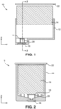
- the shape of the melamine foam is not particularly limited or critical to the disclosed embodiments and thus may have any shape that is suitable for use in a fluid cartridge. Particularly useful foam shapes may include cylindrical foam and rectangular prism-shaped foam. Cross-sectional views of typical fluid cartridges containing melamine foam inserts are illustrated in FIGs. 1 and 2 .
- the fluid cartridge 10 includes a cartridge body 12 for holding a melamine foam material 14 that is impregnated with a fluid such as ink.
- the cartridge body also includes a fluid ejection head 16 that is activated to dispense fluid from the cartridge 10.
- the foam 14 is in fluid contact with a filter 18 disposed on a filter tower structure 20 for feeding the fluid to the ejection head 16 and the foam 14 induces a backpressure within the cartridge body 12 to prevent fluid from drooling out of the ejection head 16.
- a cover 22 is applied to the cartridge body 12 to retain the fluid in the cartridge 10.
- the melamine foam 14 is typically filled with a fluid such as a water-based ink, a solvent based ink, or other water- or solvent-based fluid.
- a fluid such as a water-based ink, a solvent based ink, or other water- or solvent-based fluid.
- the amount of fluid filling the void spaces or pores in the foam may range from about 50 to about 100 % of the capacity of the foam to retain the fluid. As the amount of fluid approaches the 100 % capacity of the foam, there is a tendency for the fluid to leak from the foam 14 and accumulate in void areas or spaces of the cartridge body 12. Since the foam 14 cannot maintain a backpressure on fluid that is not within the void spaces of the foam, i.e., the fluid that has leaked out of the foam, the fluid may leak from any opening or unsealed portion of the cartridge body 12.
- One method according to an embodiment of the disclosure for reducing the amount of fluid that leaks out of the foam 14 and for improving the retention of fluid in the foam 14 is to apply a hydrophobic coating to one or more outer surface of the foam 14.
- the hydrophobic coating acts like a barrier to prevent the fluid in the foam 14 from moving past the coated outside surface(s) of the foam 14 as long as the surface tension of the fluid in the foam is higher than the surface energy of the hydrophobic coating.
- the hydrophobic coating barrier assists in retaining the fluid in the foam 14 during shipment or long-term storage of the fluid cartridge 10.
- the foam 14 is a cylindrical or rectangular prism-shaped foam 14 having at least one uncoated hydrophilic surface and two or more surfaces coated with a hydrophobic material. In some embodiments the foam 14 is a rectangular prism-shaped hydrophilic open-cell foam 14 having one uncoated hydrophilic surface and five surfaces coated with the hydrophobic material. In other embodiments, the foam has a cylindrical or rectangular prism-shaped hydrophilic open-cell foam body having only one uncoated hydrophilic surface.
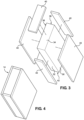
- FIGs. 3 and 4 are somewhat schematic illustrations of a foam 14 according to the disclosure having sides 30, 32, 34, 36 and 38 coated with a hydrophobic material 40 so that only one side 42 remains uncoated.
- the uncoated side 42 will be in contact with the filter 18 in the cartridge body so that the fluid can flow from the foam 14 into the filter tower structure 20 and out of the ejection head 16 during a fluid ejection sequence.
- the hydrophobic material 40 reduces or prevents fluid from leaking out of the foam 14 through sides 30, 32, 34, 36 and 38.
- the side 42 may be partially coated so that an uncoated area remains adjacent to the filter 18.
- Flow into the filter 18 from the uncoated area of side 42 of the foam 14 is provided by capillary actions through the foam 14 and filter 18 in the area of contact between the foam 14 and the material of the filter 18. If fluidic contact between the foam 14 and filter 18 is broken, the ejection head will de-prime due to lack of fluid flow.
- the fluid flow rate is determined by the surface energy of the foam, the foam density, the number of pores per unit area of the foam, and the free volume of the foam. Other factors that affect the fluid flow rate include the filter pore size and number of filter layer, the viscosity of the fluid, the surface tension of the fluid and the column height of fluid relative to the fluid ejection head.
- the uncoated area of side 42 of the foam is selected to provide a fluid flow rate ranging from 0.1 to about 19 mL per minute to the fluid ejection head 16. Otherwise, the fluid ejection head 16 may de-prime and thus fail to eject fluid.
- hydrophobic materials may be used to coat the sides 30, 32, 34, 36, and 38 of the foam 14, including, but not limited to: fluorinated hydrocarbons, siloxanes, hydrocarbon compounds having 6 to 20 carbon atoms, and other compounds that when coated onto the sides of the foam 14 provide a water contact angle of greater then 90 degrees.
- the selected hydrophobic compound to be used is soluble in a low boiling point organic solvent.
- the low boiling point solvent may be flashed off during a drying process leaving an amount of hydrophobic coating on the surfaces 30, 32, 34, 36, and 38 of the foam 14.
- a hydrophobic material that can either react on the surface of the melamine foam and/or cross link and encapsulated fibers of the melamine foam may be used.
- a hydrophobic material that reacts with or cross links with the melamine foam material is preferable since it would eliminate the possibility of the hydrophobic material being mixed with the hydrophilic fluid.
- the hydrophobic material provides a coating on the melamine foam having a thickness ranging from about 2 nm using gas deposition to about 500 ⁇ m using a dip coating method.
- Various methods may be used to coat the surfaces of a melamine foam with a hydrophobic coating material.
- the methods may include, but are not limited to, dipping the surfaces of foam in the hydrophobic material, spray coating the foam with the hydrophobic material, roll coating the hydrophobic material onto the surface of the foam, brushing the hydrophobic material onto surfaces of the foam, gas deposition of the hydrophobic coating, and stamping the surfaces of the foam with the a stamp pad impregnated with the hydrophobic material.
- the coated hydrophobic material may then be dried for five to 20 minutes at a temperature ranging from about 100 to about 120 degrees C depending on the solvent used for the hydrophobic material.
- one surface of a melamine foam was coated with 6 to 9 ⁇ m of a commercial hydrophobic solution containing 75 to 95 wt.% 3-ethoxy-1,1,1,2,3,4,4,5,5,6,6,6-dodecafluoro-2-trifluoromethyl-hexane and a from 5 to 25 wt.% of a proprietary metal complex blend sold under the tradename ACULON NANOPROOF 5.0.
- the coating was applied by dip-coating the surface into a container holding the hydrophobic coating material. After dip coating the foam, the foam was baked for 10 minutes at 110 °C.
- the water contact angle of the coated side of the foam was about 118° and the oil contact angle of the coating was about 75°.
- the foam was then filled with ⁇ 50mL of water and placed in two different orientations in contact with a paper towel.
- first orientation an uncoated surface of the foam was placed in contact with the paper towel which resulted in wicking of water onto the paper towel.
- second orientation the coated surface of the foam was placed in contact with the paper towel. No wicking of water onto the paper towel was observed when the coated surface was in contact with the paper towel.
- a hydrophobic coating solution containing 50 to 52 wt.% ethanol and 42 to 46 wt.% of a mixture of 2-(difluoromethoxymethyl)-1,1,1,2,3,3,3-heptafluoropropane and 4-methoxy-1,1,1,2,2,3,3,4,4-nonafluorobutane sold under the tradename ACULON AL-B.
- the coated foam was dried for 10 minutes at 110 °C.
- the water contact angle of the coated side of the foam was about 116° and the oil contact angle of the coating was about 80°.
- the foam was then filled with ⁇ 50mL of water.
- the uncoated surface was placed in contact with a filter. No wicking of water was evident on any of the five coated surfaces of the foam.
Landscapes
- Life Sciences & Earth Sciences (AREA)
- Engineering & Computer Science (AREA)
- Wood Science & Technology (AREA)
- Containers And Packaging Bodies Having A Special Means To Remove Contents (AREA)
- Ink Jet (AREA)
- Application Of Or Painting With Fluid Materials (AREA)
Abstract
A fluid ejection cartridge (10) having a cartridge body (12) with a cavity therein and an ejection head (16) attached to an external surface of the cartridge body (12) opposite the cavity. A cylindrical or a rectangular prism-shaped body (14) made of a hydrophilic open-cell foam material is disposed in the cavity of the cartridge body (12). The cylindrical or rectangular prism-shaped body (14) has at least one uncoated hydrophilic surface (42) and two or more surfaces (30, 32, 34, 36, 38) coated with a hydrophobic material (40).
Description
- The disclosure is directed to an improved foam material for fluid ejection cartridges and to a method for improving fluid retention in the foam material during shipping and storage of the fluid ejection cartridges.
- Fluid ejection cartridges often contain backpressure devices such as foam materials to prevent drooling of fluid from the ejection head and to provide a source of fluid for ejection. A common foam material used in fluid cartridges is a melamine foam material which is hydrophilic. Melamine foam is a condensate of melamine and formaldehyde and has the following typical chemical structure:

- The hydrophilicity of melamine foam enables high efficiencies from a fluid storage and ejection perspective. Fluid delivery efficiencies from the hydrophilic foam may range from about 90 to about 92 %. Higher fluid filling capacities compared to polyurethane foams are possible due to the hydrophilic nature of the melamine foam since the melamine foam has approximately 99.8 % free volume for fluid. Unfortunately, the hydrophilicity of the melamine foam also causes challenges during shipping and long-term storage. Movement of fluid out of the foam during shipping and storage of the fluid ejection cartridges is a problem particularly for higher levels of fluid in the fluid cartridges. Fluid leakage from the foam is also evident depending on the orientation of the fluid ejection cartridge during storage. Accordingly, what is needed is a hydrophilic foam material that retains a high level of fluid therein, particularly during shipping and storage of the fluid ejection cartridges containing the foam.
- In view of the foregoing an embodiment of the disclosure provides a fluid ejection cartridge having a cartridge body having a cavity therein and an ejection head attached to an external surface of the cartridge body opposite the cavity. A cylindrical or a rectangular prism-shaped body made of a hydrophilic open-cell foam material is disposed in the cavity of the cartridge body. The cylindrical or rectangular prism-shaped body includes at least one uncoated hydrophilic surface and two or more coated surfaces coated with a hydrophobic material.
- In another embodiment there is provided a method for improving fluid retention in an open-cell foam for a fluid ejection cartridge. The method includes coating two or more surfaces of a cylindrical or rectangular prism-shaped hydrophilic open-cell foam body with a hydrophobic material so that at least one surface of the cylindrical or rectangular prism-shaped hydrophilic open-cell foam body remains uncoated. The hydrophobic material is cured on the two or more surfaces to provide hydrophobic surfaces on the two or more surfaces of the cylindrical or rectangular prism-shaped hydrophilic open-cell foam body.
- In another embodiment there is provided a method for improving the fluid retention in a fluid ejection cartridge containing a hydrophilic fluid. The method includes providing a cylindrical or rectangular prism-shaped open cell foam body; coating all but one surface of the cylindrical or rectangular prism-shaped open cell foam body with a hydrophobic material; curing the hydrophobic material on the coated surfaces of the cylindrical or rectangular prism-shaped open cell foam body; inserting the cylindrical or rectangular prism-shaped open cell foam body into the fluid ejection cartridge; filling the cylindrical or rectangular prism-shaped open cell foam body with a fluid; and sealing the cylindrical or rectangular prism-shaped open cell foam body in the fluid ejection cartridge.
- In some embodiments, the hydrophilic open-cell foam material is a melamine foam material.
- In some embodiments, the hydrophobic material is reactive with the two or more coated surfaces of the cylindrical or rectangular prism-shaped body comprising the melamine foam material.
- In some embodiments, the hydrophobic material cross-links and encapsulates fibers of the melamine foam material.
- In some embodiments, the hydrophobic material is selected from fluorinated hydrocarbons, siloxanes, hydrocarbon compounds having from 6 to 20 carbon atoms, and coating compounds that provide a contact angle of greater than 90 degrees.
- In some embodiments, the rectangular prism-shaped hydrophilic open-cell foam body has one uncoated hydrophilic surface and five coated surfaces coated with the hydrophobic material.
- In some embodiments, the cylindrical or rectangular prism-shaped body has only one uncoated hydrophilic surface.
- In some embodiments, the two or more surfaces are coated with the hydrophobic material using a method selected from roll coating the two or more surfaces, dip-coating the two or more surfaces, spray-coating the two or more surfaces, brush coating the two or more surfaces, and stamp coating the two or more surfaces.
- In some embodiments, the two or more coated surfaces have a hydrophobic coating thickness ranging from about 2 nm to about 500 µm.
- In some embodiments, the rectangular prism-shaped body has one partially coated surface partially coated with the hydrophobic material and five coated surfaces fully coated with the hydrophobic material, so that the partially coated surface is configured to provide a fluid flow rate ranging from about 0.1 to about 19 mL per minute to the ejection head.
- An advantage of the embodiments disclosed herein is that the fluid cartridges containing hydrophobic coated foam materials tend to retain fluid much better and for a longer period of time than conventional fluid cartridges containing uncoated foam materials. Accordingly, the improved fluid cartridges disclosed herein may be transported and stored without noticeable fluid leakage from the cartridges and without having to be concerned with fluid cartridge orientation during shipping and storage.
-
-
FIG. 1 is a cross-sectional view, not to scale, of a fluid cartridge containing a foam insert according to an embodiment of the disclosure. -
FIG. 2 is a cross-sectional view, not to scale, of the fluid cartridge ofFIG. 1 through section 2-2 thereof. -
FIG. 3 is a schematic perspective, exploded view, not to scale, of a foam insert according to an embodiment of the disclosure. -
FIG. 4 is a schematic perspective view, not to scale, of the foam insert ofFIG. 3 containing a hydrophobic coating. - For the purposes of this disclosure, the term "melamine foam" means a hydrophilic open-cell foam made from a condensation reaction between melamine and formaldehyde having the general structure:

- The shape of the melamine foam is not particularly limited or critical to the disclosed embodiments and thus may have any shape that is suitable for use in a fluid cartridge. Particularly useful foam shapes may include cylindrical foam and rectangular prism-shaped foam. Cross-sectional views of typical fluid cartridges containing melamine foam inserts are illustrated in
FIGs. 1 and 2 . Thefluid cartridge 10 includes acartridge body 12 for holding amelamine foam material 14 that is impregnated with a fluid such as ink. The cartridge body also includes afluid ejection head 16 that is activated to dispense fluid from thecartridge 10. Thefoam 14 is in fluid contact with afilter 18 disposed on afilter tower structure 20 for feeding the fluid to theejection head 16 and thefoam 14 induces a backpressure within thecartridge body 12 to prevent fluid from drooling out of theejection head 16. Acover 22 is applied to thecartridge body 12 to retain the fluid in thecartridge 10. - The
melamine foam 14 is typically filled with a fluid such as a water-based ink, a solvent based ink, or other water- or solvent-based fluid. The amount of fluid filling the void spaces or pores in the foam may range from about 50 to about 100 % of the capacity of the foam to retain the fluid. As the amount of fluid approaches the 100 % capacity of the foam, there is a tendency for the fluid to leak from thefoam 14 and accumulate in void areas or spaces of thecartridge body 12. Since thefoam 14 cannot maintain a backpressure on fluid that is not within the void spaces of the foam, i.e., the fluid that has leaked out of the foam, the fluid may leak from any opening or unsealed portion of thecartridge body 12. - One method according to an embodiment of the disclosure for reducing the amount of fluid that leaks out of the
foam 14 and for improving the retention of fluid in thefoam 14 is to apply a hydrophobic coating to one or more outer surface of thefoam 14. For a foam containing a water-based or solvent-based fluid, the hydrophobic coating acts like a barrier to prevent the fluid in thefoam 14 from moving past the coated outside surface(s) of thefoam 14 as long as the surface tension of the fluid in the foam is higher than the surface energy of the hydrophobic coating. The hydrophobic coating barrier assists in retaining the fluid in thefoam 14 during shipment or long-term storage of thefluid cartridge 10. - In some embodiments, the
foam 14 is a cylindrical or rectangular prism-shaped foam 14 having at least one uncoated hydrophilic surface and two or more surfaces coated with a hydrophobic material. In some embodiments thefoam 14 is a rectangular prism-shaped hydrophilic open-cell foam 14 having one uncoated hydrophilic surface and five surfaces coated with the hydrophobic material. In other embodiments, the foam has a cylindrical or rectangular prism-shaped hydrophilic open-cell foam body having only one uncoated hydrophilic surface.FIGs. 3 and 4 are somewhat schematic illustrations of afoam 14 according to thedisclosure having sides hydrophobic material 40 so that only oneside 42 remains uncoated. Theuncoated side 42 will be in contact with thefilter 18 in the cartridge body so that the fluid can flow from thefoam 14 into thefilter tower structure 20 and out of theejection head 16 during a fluid ejection sequence. In this way, thehydrophobic material 40 reduces or prevents fluid from leaking out of thefoam 14 throughsides - In some embodiments, the
side 42 may be partially coated so that an uncoated area remains adjacent to thefilter 18. Flow into thefilter 18 from the uncoated area ofside 42 of thefoam 14 is provided by capillary actions through thefoam 14 and filter 18 in the area of contact between thefoam 14 and the material of thefilter 18. If fluidic contact between thefoam 14 andfilter 18 is broken, the ejection head will de-prime due to lack of fluid flow. The fluid flow rate is determined by the surface energy of the foam, the foam density, the number of pores per unit area of the foam, and the free volume of the foam. Other factors that affect the fluid flow rate include the filter pore size and number of filter layer, the viscosity of the fluid, the surface tension of the fluid and the column height of fluid relative to the fluid ejection head. Based on the foregoing, the uncoated area ofside 42 of the foam is selected to provide a fluid flow rate ranging from 0.1 to about 19 mL per minute to thefluid ejection head 16. Otherwise, thefluid ejection head 16 may de-prime and thus fail to eject fluid. - A wide variety of hydrophobic materials may be used to coat the
sides foam 14, including, but not limited to: fluorinated hydrocarbons, siloxanes, hydrocarbon compounds having 6 to 20 carbon atoms, and other compounds that when coated onto the sides of thefoam 14 provide a water contact angle of greater then 90 degrees. - Ideally the selected hydrophobic compound to be used is soluble in a low boiling point organic solvent. The low boiling point solvent may be flashed off during a drying process leaving an amount of hydrophobic coating on the
surfaces foam 14. In some embodiments, a hydrophobic material that can either react on the surface of the melamine foam and/or cross link and encapsulated fibers of the melamine foam may be used. A hydrophobic material that reacts with or cross links with the melamine foam material is preferable since it would eliminate the possibility of the hydrophobic material being mixed with the hydrophilic fluid. In some embodiments, the hydrophobic material provides a coating on the melamine foam having a thickness ranging from about 2 nm using gas deposition to about 500 µm using a dip coating method. - Various methods may be used to coat the surfaces of a melamine foam with a hydrophobic coating material. The methods may include, but are not limited to, dipping the surfaces of foam in the hydrophobic material, spray coating the foam with the hydrophobic material, roll coating the hydrophobic material onto the surface of the foam, brushing the hydrophobic material onto surfaces of the foam, gas deposition of the hydrophobic coating, and stamping the surfaces of the foam with the a stamp pad impregnated with the hydrophobic material. The coated hydrophobic material may then be dried for five to 20 minutes at a temperature ranging from about 100 to about 120 degrees C depending on the solvent used for the hydrophobic material.
- The following non-limiting examples are provided for the purposes of illustrating aspects of the disclosure.
- In this example, one surface of a melamine foam was coated with 6 to 9 µm of a commercial hydrophobic solution containing 75 to 95 wt.% 3-ethoxy-1,1,1,2,3,4,4,5,5,6,6,6-dodecafluoro-2-trifluoromethyl-hexane and a from 5 to 25 wt.% of a proprietary metal complex blend sold under the tradename ACULON NANOPROOF 5.0. The coating was applied by dip-coating the surface into a container holding the hydrophobic coating material. After dip coating the foam, the foam was baked for 10 minutes at 110 °C. The water contact angle of the coated side of the foam was about 118° and the oil contact angle of the coating was about 75°. The foam was then filled with ~50mL of water and placed in two different orientations in contact with a paper towel. In the first orientation, an uncoated surface of the foam was placed in contact with the paper towel which resulted in wicking of water onto the paper towel. In the second orientation, the coated surface of the foam was placed in contact with the paper towel. No wicking of water onto the paper towel was observed when the coated surface was in contact with the paper towel.
- In this example, five of six surfaces of a melamine foam were coated with 2 to 4 nm of a hydrophobic coating solution containing 50 to 52 wt.% ethanol and 42 to 46 wt.% of a mixture of 2-(difluoromethoxymethyl)-1,1,1,2,3,3,3-heptafluoropropane and 4-methoxy-1,1,1,2,2,3,3,4,4-nonafluorobutane sold under the tradename ACULON AL-B. The coated foam was dried for 10 minutes at 110 °C. The water contact angle of the coated side of the foam was about 116° and the oil contact angle of the coating was about 80°. The foam was then filled with ~50mL of water. The uncoated surface was placed in contact with a filter. No wicking of water was evident on any of the five coated surfaces of the foam.
- For the purposes of this specification and appended claims, unless otherwise indicated, all numbers expressing quantities, percentages or proportions, and other numerical values used in the specification and claims, are to be understood as being modified in all instances by the term "about." Accordingly, unless indicated to the contrary, the numerical parameters set forth in the following specification and attached claims are approximations that can vary depending upon the desired properties sought to be obtained by the present disclosure. At the very least, and not as an attempt to limit the application of the doctrine of equivalents to the scope of the claims, each numerical parameter should at least be construed in light of the number of reported significant digits and by applying ordinary rounding techniques.
- While particular embodiments have been described, alternatives, modifications, variations, improvements, and substantial equivalents that are or can be presently unforeseen can arise to applicants or others skilled in the art. Accordingly, the appended claims as filed and as they can be amended are intended to embrace all such alternatives, modifications, variations, improvements, and substantial equivalents.
Claims (20)
- A fluid ejection cartridge (10) comprising:a cartridge body (12) having a cavity therein and an ejection head (16) attached to an external surface of the cartridge body (12) opposite the cavity, anda cylindrical body or a rectangular prism-shaped body (14) comprised of a hydrophilic open-cell foam material disposed in the cavity of the cartridge body (12), wherein the cylindrical body or the rectangular prism-shaped body (14) further comprises at least one uncoated hydrophilic surface (42) and two or more coated surfaces (30, 32, 34, 36, 38) fully coated with a hydrophobic material (40).
- The fluid ejection cartridge (10) of claim 1, wherein the hydrophilic open-cell foam material comprises a melamine foam material.
- The fluid ejection cartridge (10) of claim 2, wherein the hydrophobic material (40) is reactive with the two or more coated surfaces (30, 32, 34, 36, 38) of the cylindrical body or the rectangular prism-shaped body (14) comprising the melamine foam material.
- The fluid ejection cartridge (10) of claim 3, wherein the hydrophobic material (40) cross-links and encapsulates fibers of the melamine foam material.
- The fluid ejection cartridge (10) of claim 1, wherein the hydrophobic material (40) is selected from the group consisting of fluorinated hydrocarbons, siloxanes, hydrocarbon compounds having from 6 to 20 carbon atoms, and coating compounds that provide a contact angle of greater than 90 degrees.
- The fluid ejection cartridge (10) of claim 1, wherein the rectangular prism-shaped body (14) has one uncoated hydrophilic surface (42) and five coated surfaces (30, 32, 34, 36, 38) fully coated with the hydrophobic material (40).
- The fluid ejection cartridge (10) of claim 1, wherein the rectangular prism-shaped body (14) has one partially coated surface (42) partially coated with the hydrophobic material (40) and five coated surfaces (30, 32, 34, 36, 38) fully coated with the hydrophobic material (40), so that the partially coated surface (42) is configured to provide a fluid flow rate ranging from about 0.1 to about 19 mL per minute to the ejection head (16).
- The fluid ejection cartridge (10) of claim 1, wherein the cylindrical body or the rectangular prism-shaped body (14) has only one uncoated hydrophilic surface (42).
- The fluid ejection cartridge (10) of claim 1, wherein the two or more coated surfaces (30, 32, 34, 36, 38) have a hydrophobic coating thickness ranging from about 2 nm to about 500 µm.
- A method for improving fluid retention in an open-cell foam for a fluid ejection cartridge (10), comprisingcoating two or more surfaces (30, 32, 34, 36, 38) of a cylindrical hydrophilic open-cell foam body or a rectangular prism-shaped hydrophilic open-cell foam body (14) with a hydrophobic material (40) so that at least one surface (42) of the cylindrical hydrophilic open-cell foam body or the rectangular prism-shaped hydrophilic open-cell foam body (14) remains uncoated, andcuring the hydrophobic material (40) on the two or more surfaces (30, 32, 34, 36, 38) to provide hydrophobic surfaces (30, 32, 34, 36, 38) on the two or more surfaces (30, 32, 34, 36, 38) of the cylindrical hydrophilic open-cell foam body or the rectangular prism-shaped hydrophilic open-cell foam body (14).
- The method of claim 10, wherein the cylindrical hydrophilic open-cell foam body or the rectangular prism-shaped hydrophilic open-cell foam body (14) comprises only one hydrophilic surface (42).
- The method of claim 10, wherein the two or more surfaces (30, 32, 34, 36, 38) are coated with the hydrophobic material (40) using a method selected from the group consisting of roll coating the two or more surfaces (30, 32, 34, 36, 38), dip-coating the two or more surfaces (30, 32, 34, 36, 38), spray-coating the two or more surfaces (30, 32, 34, 36, 38), brush coating the two or more surfaces (30, 32, 34, 36, 38), and stamp coating the two or more surfaces (30, 32, 34, 36, 38).
- The method of claim 10, wherein the cylindrical hydrophilic open-cell foam body or the rectangular prism-shaped hydrophilic open-cell foam body (14) comprises a melamine foam material.
- The method of claim 13, wherein the curing step comprises reacting the hydrophobic material (40) with the two or more surfaces (30, 32, 34, 36, 38) of the cylindrical hydrophilic open-cell foam body or the rectangular prism-shaped hydrophilic open-cell foam body (14) comprising the melamine foam material.
- The method of claim 13, wherein the curing step comprises cross-linking and encapsulating fibers of the melamine foam material with the hydrophobic material (40).
- The method of claim 10, wherein five surfaces (30, 32, 34, 36, 38) of the rectangular prism-shaped hydrophilic open-cell foam body (14) are coated with the hydrophobic material (40).
- A method for improving the fluid retention in a fluid ejection cartridge (10) containing a hydrophilic fluid comprising:providing a cylindrical open cell foam body or a rectangular prism-shaped open cell foam body (14);coating all but one surface (30, 32, 34, 36, 38, 42) of the cylindrical open cell foam body or the rectangular prism-shaped open cell foam body (14) with a hydrophobic material (40);curing the hydrophobic material (40) on the coated surfaces (30, 32, 34, 36, 38) of the cylindrical open cell foam body or the rectangular prism-shaped open cell foam body (14);inserting the cylindrical open cell foam body or the rectangular prism-shaped open cell foam body (14) into the fluid ejection cartridge (10);filling the cylindrical open cell foam body or the rectangular prism-shaped open cell foam body (14) with a fluid; andsealing the cylindrical open cell foam body or the rectangular prism-shaped open cell foam body (14) in the fluid ejection cartridge (10).
- The method of claim 17, wherein the cylindrical open cell foam body or the rectangular prism-shaped open cell foam body (14) comprises a melamine foam material.
- The method of claim 18, wherein the curing step comprises reacting the hydrophobic material (40) with the melamine foam material.
- The method of claim 18, wherein the curing step comprises cross-linking and encapsulating fibers of the melamine foam material with the hydrophobic material (40).
Applications Claiming Priority (1)
| Application Number | Priority Date | Filing Date | Title |
|---|---|---|---|
| US18/183,979 US12565045B2 (en) | 2023-03-15 | 2023-03-15 | Hydrophilic foam having improved fluid retention |
Publications (1)
| Publication Number | Publication Date |
|---|---|
| EP4431296A1 true EP4431296A1 (en) | 2024-09-18 |
Family
ID=90057615
Family Applications (1)
| Application Number | Title | Priority Date | Filing Date |
|---|---|---|---|
| EP24159363.1A Pending EP4431296A1 (en) | 2023-03-15 | 2024-02-23 | Hydrophilic foam having improved fluid retention |
Country Status (4)
| Country | Link |
|---|---|
| US (1) | US12565045B2 (en) |
| EP (1) | EP4431296A1 (en) |
| JP (1) | JP2024132996A (en) |
| CN (1) | CN118663454A (en) |
Families Citing this family (2)
| Publication number | Priority date | Publication date | Assignee | Title |
|---|---|---|---|---|
| US12565045B2 (en) | 2023-03-15 | 2026-03-03 | Brady Worldwide, Inc. | Hydrophilic foam having improved fluid retention |
| US12600130B2 (en) | 2023-08-22 | 2026-04-14 | Brady Worldwide, Inc. | Ejection head nozzle flooding control |
Citations (5)
| Publication number | Priority date | Publication date | Assignee | Title |
|---|---|---|---|---|
| US6709092B2 (en) * | 1999-12-06 | 2004-03-23 | Canon Kabushiki Kaisha | Recording liquid feed path, recording liquid container, and recording liquid feed device having same, as well as surface modifying method for the recording liquid feed device |
| US6874875B1 (en) * | 2001-06-13 | 2005-04-05 | Nu-Kote International, Inc. | Ink cartridge with compressed ink absorbing member therein |
| US20080309740A1 (en) * | 2007-06-13 | 2008-12-18 | Charles Stanley Aldrich | Fluid Supply Tank Ventilation For A Micro-Fluid Ejection Head |
| US20170058243A1 (en) * | 2015-08-26 | 2017-03-02 | EMULATE, Inc. | Droplet fluid connections |
| WO2019013753A1 (en) * | 2017-07-10 | 2019-01-17 | Hewlett-Packard Development Company, L.P. | Printing fluid cartridge |
Family Cites Families (59)
| Publication number | Priority date | Publication date | Assignee | Title |
|---|---|---|---|---|
| DE2822886A1 (en) | 1978-05-26 | 1979-11-29 | Hoechst Ag | TUBE-SHAPED PACKAGING SHELL BASED ON CELLULOSE HYDRATE WITH FIBER INSERT IN THE SHELL WALL AND OPTICALLY EFFECTIVE CHEMICAL COMPOUND ON THE SURFACE AS WELL AS THE PROCESS FOR THEIR PRODUCTION |
| JPS62238799A (en) | 1986-04-10 | 1987-10-19 | 堀 二郎 | Writing utensil |
| JPH0538867Y2 (en) | 1987-04-11 | 1993-09-30 | ||
| US4929969A (en) | 1989-08-25 | 1990-05-29 | Eastman Kodak Company | Ink supply construction and printing method for drop-on-demand ink jet printing |
| JP3255659B2 (en) | 1990-07-10 | 2002-02-12 | キヤノン株式会社 | Recording apparatus and ink jet cartridge used therein |
| JP3078066B2 (en) | 1991-10-30 | 2000-08-21 | 東芝電池株式会社 | Air battery |
| JPH05212997A (en) | 1991-12-10 | 1993-08-24 | Sakura Color Prod Corp | Applicator |
| JP3043926B2 (en) | 1993-08-20 | 2000-05-22 | キヤノン株式会社 | ink cartridge |
| JP2595418Y2 (en) | 1993-05-25 | 1999-05-31 | シヤチハタ工業株式会社 | Refill container for marking pen |
| CA2241801C (en) | 1993-08-20 | 2004-02-10 | Canon Kabushiki Kaisha | Ink cartridge |
| FR2719806B1 (en) | 1994-05-11 | 1996-08-02 | Conte | Writing article in liquid ink, in particular solvent-based. |
| JPH0811320A (en) | 1994-07-04 | 1996-01-16 | Canon Inc | Liquid storage container and liquid supply container |
| JP3564881B2 (en) | 1996-06-28 | 2004-09-15 | ぺんてる株式会社 | Writing implement |
| AUPO798697A0 (en) | 1997-07-15 | 1997-08-07 | Silverbrook Research Pty Ltd | Data processing method and apparatus (ART51) |
| JP3720586B2 (en) | 1997-07-30 | 2005-11-30 | キヤノン株式会社 | Ink tank, ink absorber used in the ink tank, and ink tank manufacturing method |
| FR2793426B1 (en) | 1999-05-14 | 2001-08-17 | Conte | PROCESS FOR TREATING A LONGIFORM ELEMENT FOR FORMING A WRITING POINT AND WRITING POINT OBTAINED |
| US6796645B2 (en) | 1999-12-06 | 2004-09-28 | Canon Kabushiki Kaisha | Surface reformed fiber body, liquid container using fiber absorber, and method of producing fiber absorber for use in liquid ejection |
| JP3436728B2 (en) | 2000-05-08 | 2003-08-18 | 株式会社 ヒックス | Writing implement |
| JP3931722B2 (en) | 2001-05-31 | 2007-06-20 | ぺんてる株式会社 | Applicator |
| US6702894B2 (en) * | 2001-10-24 | 2004-03-09 | Hewlett-Packard Development Company, L.P. | Fluid ejection cartridge and system for dispensing a bioactive substance |
| GB2396311B (en) | 2001-08-24 | 2005-11-30 | Dober Chemical Corp | Controlled release of additives in cooling systems |
| JP3788609B2 (en) | 2001-08-29 | 2006-06-21 | 三菱鉛筆株式会社 | Ink storage for writing instruments |
| JP3849549B2 (en) | 2002-02-28 | 2006-11-22 | ぺんてる株式会社 | Applicator |
| JP2004066476A (en) | 2002-08-01 | 2004-03-04 | Mitsubishi Pencil Co Ltd | Ink storage member for writing implements |
| TWI260280B (en) | 2002-05-31 | 2006-08-21 | Pentel Kk | Applicator |
| JP4321118B2 (en) | 2002-05-31 | 2009-08-26 | ぺんてる株式会社 | Applicator |
| FR2852301B1 (en) | 2003-03-13 | 2006-02-10 | Valois Sas | DEVICE FOR DISPENSING FLUID PRODUCT |
| JP4662527B2 (en) | 2003-07-08 | 2011-03-30 | エステー産業株式会社 | Drip-type ink supply device, ink supply method and supply kit |
| US7147311B2 (en) | 2004-03-25 | 2006-12-12 | Hewlett-Packard Development Company, L.P. | Fluid supply media |
| KR100562281B1 (en) | 2004-06-15 | 2006-03-22 | 주식회사모나미 | Valve type writing instruments |
| WO2005123416A1 (en) | 2004-06-22 | 2005-12-29 | Hori, Yayoi | Liquid feed device |
| JPWO2006059628A1 (en) | 2004-12-01 | 2008-06-05 | 中山工業株式会社 | Viscous fluid cartridge |
| DE102005031851A1 (en) | 2005-07-06 | 2007-01-18 | Basf Ag | Liquid storage of melamine / formaldehyde foam |
| JP2008162140A (en) | 2006-12-28 | 2008-07-17 | Mitsubishi Pencil Co Ltd | Penetration seal holding structure |
| WO2009005974A1 (en) | 2007-06-28 | 2009-01-08 | Georgia-Pacific Chemicals Llc | Reducing formaldehyde emissions |
| JP4246787B1 (en) | 2007-11-14 | 2009-04-02 | ジット株式会社 | Ink storage container |
| JPWO2009072656A1 (en) | 2007-12-07 | 2011-04-28 | エステー産業株式会社 | Liquid storage container |
| JP5169395B2 (en) | 2008-04-07 | 2013-03-27 | トヨタ自動車株式会社 | Coating apparatus and coating method |
| JP5227084B2 (en) | 2008-05-27 | 2013-07-03 | 愛三工業株式会社 | Granulated heat storage material and manufacturing method thereof |
| WO2009145020A1 (en) | 2008-05-27 | 2009-12-03 | 大阪ガスケミカル株式会社 | Process for producing heat storage material, heat storage material, adsorbent material with heat storage function and canister |
| US20100024898A1 (en) | 2008-07-29 | 2010-02-04 | General Electric Company | Fuel tank vent including a membrane separator |
| AU2010206149A1 (en) | 2009-01-23 | 2011-08-18 | Akzo Nobel Coatings International B.V. | Packaging for two or more fluids |
| JP6005344B2 (en) | 2011-07-05 | 2016-10-12 | 科研製薬株式会社 | Nail ringworm medicine applicator |
| US10051939B2 (en) | 2013-04-22 | 2018-08-21 | Inoac Packaging Group, Inc. | Cosmetic devices, precursor therefor and related methods |
| GB201312362D0 (en) | 2013-07-10 | 2013-08-21 | Leafgreen Ltd | A divider part for containers |
| JP5998163B2 (en) | 2013-07-22 | 2016-09-28 | 株式会社 エポックケミカル | Valve type liquid material exuding tool |
| KR101410746B1 (en) | 2014-01-08 | 2014-06-24 | 김진우 | Liquid beauty expenses impregnation method that use porosity pad and this for liquid beauty expenses impregnation |
| JP5933793B1 (en) | 2015-08-20 | 2016-06-15 | 株式会社3S | Applicator |
| KR101774140B1 (en) | 2016-01-19 | 2017-09-01 | 주식회사 엘지화학 | Preparation method and apparatus of aerogel sheet |
| JP6042005B1 (en) | 2016-02-09 | 2016-12-14 | 株式会社3S | Applicator and manufacturing method thereof |
| US9962948B1 (en) | 2016-12-22 | 2018-05-08 | Funai Electric Co., Ltd. | Fluid delivery devices |
| CN108501536A (en) | 2017-02-28 | 2018-09-07 | 迈博高分子材料(宁波)有限公司 | A kind of printer ink cartridge |
| EP3424746B1 (en) | 2017-05-12 | 2021-05-19 | Qingdao Changlong Stationery CO., LTD | Direct liquid type writing tool |
| DE102017215754A1 (en) | 2017-09-07 | 2019-03-07 | Robert Bosch Gmbh | Tank with an inner container and an outer shell and method of manufacturing the tank |
| JP2021007421A (en) | 2017-09-29 | 2021-01-28 | 株式会社3S | Applicator |
| KR102198089B1 (en) | 2019-05-27 | 2021-01-04 | 나노화인테크 주식회사 | Nano Porous Support |
| JP7784816B2 (en) | 2021-03-29 | 2025-12-12 | 株式会社パイロットコーポレーション | A refill product comprising colored pencil leads and a refill case containing the leads. |
| US12565045B2 (en) | 2023-03-15 | 2026-03-03 | Brady Worldwide, Inc. | Hydrophilic foam having improved fluid retention |
| US12629943B2 (en) | 2023-07-11 | 2026-05-19 | Canon Kabushiki Kaisha | Ink storage container |
-
2023
- 2023-03-15 US US18/183,979 patent/US12565045B2/en active Active
-
2024
- 2024-02-23 EP EP24159363.1A patent/EP4431296A1/en active Pending
- 2024-03-04 CN CN202410241205.2A patent/CN118663454A/en not_active Withdrawn
- 2024-03-13 JP JP2024039096A patent/JP2024132996A/en active Pending
Patent Citations (5)
| Publication number | Priority date | Publication date | Assignee | Title |
|---|---|---|---|---|
| US6709092B2 (en) * | 1999-12-06 | 2004-03-23 | Canon Kabushiki Kaisha | Recording liquid feed path, recording liquid container, and recording liquid feed device having same, as well as surface modifying method for the recording liquid feed device |
| US6874875B1 (en) * | 2001-06-13 | 2005-04-05 | Nu-Kote International, Inc. | Ink cartridge with compressed ink absorbing member therein |
| US20080309740A1 (en) * | 2007-06-13 | 2008-12-18 | Charles Stanley Aldrich | Fluid Supply Tank Ventilation For A Micro-Fluid Ejection Head |
| US20170058243A1 (en) * | 2015-08-26 | 2017-03-02 | EMULATE, Inc. | Droplet fluid connections |
| WO2019013753A1 (en) * | 2017-07-10 | 2019-01-17 | Hewlett-Packard Development Company, L.P. | Printing fluid cartridge |
Also Published As
| Publication number | Publication date |
|---|---|
| US20240308229A1 (en) | 2024-09-19 |
| US12565045B2 (en) | 2026-03-03 |
| CN118663454A (en) | 2024-09-20 |
| JP2024132996A (en) | 2024-10-01 |
Similar Documents
| Publication | Publication Date | Title |
|---|---|---|
| US12565045B2 (en) | Hydrophilic foam having improved fluid retention | |
| EP1106362B1 (en) | Surface treated fiber body, liquid container using fiber absorber and method for producing fiber absorber for use in liquid ejection | |
| US7938523B2 (en) | Fluid supply tank ventilation for a micro-fluid ejection head | |
| CN101434148B (en) | Ink storage container | |
| US6709092B2 (en) | Recording liquid feed path, recording liquid container, and recording liquid feed device having same, as well as surface modifying method for the recording liquid feed device | |
| CN100467282C (en) | liquid supply device | |
| KR20050007355A (en) | Applicator | |
| US5297883A (en) | Liquid applicator with drying prevention agent | |
| JP3436728B2 (en) | Writing implement | |
| JP3572291B2 (en) | Air management of print head using unsaturated ink | |
| JP4406424B2 (en) | Fluid product spraying equipment | |
| US5742309A (en) | Ink cartridge | |
| JP2009040050A (en) | Ink refilling apparatus for ink cartridge for inkjet printer | |
| JP3931722B2 (en) | Applicator | |
| JP5998163B2 (en) | Valve type liquid material exuding tool | |
| JP6042005B1 (en) | Applicator and manufacturing method thereof | |
| JP7784816B2 (en) | A refill product comprising colored pencil leads and a refill case containing the leads. | |
| CA2616317A1 (en) | Container made from plastics materials with a polymeric organofluorine interior coating for active-compound formulations for crop protection or protection of materials | |
| JP3255659B2 (en) | Recording apparatus and ink jet cartridge used therein | |
| WO2018157594A1 (en) | Print cartridge | |
| JP4321118B2 (en) | Applicator | |
| JPH0538867Y2 (en) | ||
| JP2595418Y2 (en) | Refill container for marking pen | |
| JPS62238799A (en) | Writing utensil | |
| JP3138121B2 (en) | Ink injection device for ink cartridge for ink jet device |
Legal Events
| Date | Code | Title | Description |
|---|---|---|---|
| PUAI | Public reference made under article 153(3) epc to a published international application that has entered the european phase |
Free format text: ORIGINAL CODE: 0009012 |
|
| STAA | Information on the status of an ep patent application or granted ep patent |
Free format text: STATUS: THE APPLICATION HAS BEEN PUBLISHED |
|
| AK | Designated contracting states |
Kind code of ref document: A1 Designated state(s): AL AT BE BG CH CY CZ DE DK EE ES FI FR GB GR HR HU IE IS IT LI LT LU LV MC ME MK MT NL NO PL PT RO RS SE SI SK SM TR |
|
| 19U | Interruption of proceedings before grant |
Effective date: 20241024 |