EP4431214A1 - Map-data-editing device, processing program creation device, and map-data-editing method - Google Patents
Map-data-editing device, processing program creation device, and map-data-editing method Download PDFInfo
- Publication number
- EP4431214A1 EP4431214A1 EP21968123.6A EP21968123A EP4431214A1 EP 4431214 A1 EP4431214 A1 EP 4431214A1 EP 21968123 A EP21968123 A EP 21968123A EP 4431214 A1 EP4431214 A1 EP 4431214A1
- Authority
- EP
- European Patent Office
- Prior art keywords
- machining
- data
- machining shape
- shapes
- edge
- Prior art date
- Legal status (The legal status is an assumption and is not a legal conclusion. Google has not performed a legal analysis and makes no representation as to the accuracy of the status listed.)
- Pending
Links
Images





Classifications
-
- B—PERFORMING OPERATIONS; TRANSPORTING
- B23—MACHINE TOOLS; METAL-WORKING NOT OTHERWISE PROVIDED FOR
- B23H—WORKING OF METAL BY THE ACTION OF A HIGH CONCENTRATION OF ELECTRIC CURRENT ON A WORKPIECE USING AN ELECTRODE WHICH TAKES THE PLACE OF A TOOL; SUCH WORKING COMBINED WITH OTHER FORMS OF WORKING OF METAL
- B23H7/00—Processes or apparatus applicable to both electrical discharge machining and electrochemical machining
- B23H7/14—Electric circuits specially adapted therefor, e.g. power supply
- B23H7/20—Electric circuits specially adapted therefor, e.g. power supply for program control, e.g. adaptive
-
- B—PERFORMING OPERATIONS; TRANSPORTING
- B23—MACHINE TOOLS; METAL-WORKING NOT OTHERWISE PROVIDED FOR
- B23H—WORKING OF METAL BY THE ACTION OF A HIGH CONCENTRATION OF ELECTRIC CURRENT ON A WORKPIECE USING AN ELECTRODE WHICH TAKES THE PLACE OF A TOOL; SUCH WORKING COMBINED WITH OTHER FORMS OF WORKING OF METAL
- B23H7/00—Processes or apparatus applicable to both electrical discharge machining and electrochemical machining
- B23H7/02—Wire-cutting
- B23H7/06—Control of the travel curve of the relative movement between electrode and workpiece
-
- G—PHYSICS
- G05—CONTROLLING; REGULATING
- G05B—CONTROL OR REGULATING SYSTEMS IN GENERAL; FUNCTIONAL ELEMENTS OF SUCH SYSTEMS; MONITORING OR TESTING ARRANGEMENTS FOR SUCH SYSTEMS OR ELEMENTS
- G05B19/00—Program-control systems
- G05B19/02—Program-control systems electric
- G05B19/18—Numerical control [NC], i.e. automatically operating machines, in particular machine tools, e.g. in a manufacturing environment, so as to execute positioning, movement or co-ordinated operations by means of program data in numerical form
- G05B19/4093—Numerical control [NC], i.e. automatically operating machines, in particular machine tools, e.g. in a manufacturing environment, so as to execute positioning, movement or co-ordinated operations by means of program data in numerical form characterised by part programming, e.g. entry of geometrical information as taken from a technical drawing, combining this with machining and material information to obtain control information, named part program, for the NC machine
-
- G—PHYSICS
- G05—CONTROLLING; REGULATING
- G05B—CONTROL OR REGULATING SYSTEMS IN GENERAL; FUNCTIONAL ELEMENTS OF SUCH SYSTEMS; MONITORING OR TESTING ARRANGEMENTS FOR SUCH SYSTEMS OR ELEMENTS
- G05B19/00—Program-control systems
- G05B19/02—Program-control systems electric
- G05B19/18—Numerical control [NC], i.e. automatically operating machines, in particular machine tools, e.g. in a manufacturing environment, so as to execute positioning, movement or co-ordinated operations by means of program data in numerical form
- G05B19/4097—Numerical control [NC], i.e. automatically operating machines, in particular machine tools, e.g. in a manufacturing environment, so as to execute positioning, movement or co-ordinated operations by means of program data in numerical form characterised by using design data to control NC machines, e.g. CAD/CAM
-
- G—PHYSICS
- G05—CONTROLLING; REGULATING
- G05B—CONTROL OR REGULATING SYSTEMS IN GENERAL; FUNCTIONAL ELEMENTS OF SUCH SYSTEMS; MONITORING OR TESTING ARRANGEMENTS FOR SUCH SYSTEMS OR ELEMENTS
- G05B2219/00—Program-control systems
- G05B2219/30—Nc systems
- G05B2219/45—Nc applications
- G05B2219/45043—EDM machine, wire cutting
-
- G—PHYSICS
- G05—CONTROLLING; REGULATING
- G05B—CONTROL OR REGULATING SYSTEMS IN GENERAL; FUNCTIONAL ELEMENTS OF SUCH SYSTEMS; MONITORING OR TESTING ARRANGEMENTS FOR SUCH SYSTEMS OR ELEMENTS
- G05B2219/00—Program-control systems
- G05B2219/30—Nc systems
- G05B2219/45—Nc applications
- G05B2219/45221—Edm, electrical discharge machining, electroerosion, ecm, chemical
-
- Y—GENERAL TAGGING OF NEW TECHNOLOGICAL DEVELOPMENTS; GENERAL TAGGING OF CROSS-SECTIONAL TECHNOLOGIES SPANNING OVER SEVERAL SECTIONS OF THE IPC; TECHNICAL SUBJECTS COVERED BY FORMER USPC CROSS-REFERENCE ART COLLECTIONS [XRACs] AND DIGESTS
- Y02—TECHNOLOGIES OR APPLICATIONS FOR MITIGATION OR ADAPTATION AGAINST CLIMATE CHANGE
- Y02P—CLIMATE CHANGE MITIGATION TECHNOLOGIES IN THE PRODUCTION OR PROCESSING OF GOODS
- Y02P90/00—Enabling technologies with a potential contribution to greenhouse gas [GHG] emissions mitigation
- Y02P90/02—Total factory control, e.g. smart factories, flexible manufacturing systems [FMS] or integrated manufacturing systems [IMS]
Definitions
- the present invention relates to a map-data-editing device (figure data edit device), a processing program creation device (machining program creation device), and a map-data-editing method (figure data edit method) that edits figure data for creating a machining program for a wire electric discharge machine.
- a map-data-editing device (figure data edit device), a processing program creation device (machining program creation device), and a map-data-editing method (figure data edit method) that edits figure data for creating a machining program for a wire electric discharge machine.
- a wire electrode of a wire electric discharge machine moves relative to a workpiece. This relative movement is controlled based on a machining program.
- the machining program is created based on CAD (Computer Aided Design) data representing a figure of a machining shape.
- the CAD data includes a plurality of machining shapes followed by the wire electrode.
- the machining shapes indicate the shapes of the products produced by the wire electric discharge machine.
- the machining shapes do not indicate a machining start position and an approach path.
- the machining start position is the position where the wire electrode starts relative movements.
- the approach path is a path (line shape) connecting the machining start position and the machining shape.
- An operator in charge of creating a machining program adds machining start positions and approach paths to figure data according to machining shapes before creating the machining program.
- the machining program is created based on CAD data to which the machining start positions and the approach paths have been added.
- JP H03-189708 A discloses a machining shape copying method. According to the disclosure, when a machining shape is copied, the machining start position corresponding to the machining shape is also copied.
- machining shape copying method for example, when a machining shape is copied, one may consider copying not only the machining start position but also the approach path.
- the present invention aims to solve the above-mentioned problems.
- the first aspect of the present invention is a figure data edit device for editing figure data indicating a plurality of machining shapes based on which a wire electric discharge machine machines one workpiece, the figure data edit method comprising: a figure acquisition unit that acquires the figure data; a group creation unit that groups the plurality of machining shapes into groups in each of which shapes are congruent or similar to each other; a path addition unit that adds a first approach path leading to a first machining shape, which is any one of the plurality of machining shapes, to the figure data in response to an operation of an operator; and an automatic path addition unit that automatically adds a second approach path leading to a second machining shape belonging to the same group as the first machining shape to the figure data so as to be congruent or similar to a figure formed by the first machining shape and the first approach path.
- a second aspect of the present invention is a machining program creation device including: a figure data edit device according to the first aspect; and a machining program creation unit that creates, based on the figure data, a machining program for instructing a relative movement of a wire electrode of the wire electric discharge machine with respect to the workpiece.
- a third aspect of the present invention is a figure data edit method for editing figure data indicating a plurality of machining shapes based on which a wire electric discharge machine machines one workpiece, comprising: a figure acquisition step that acquires the figure data; a group creation step that groups the plurality of machining shapes into groups in each of which shapes are congruent or similar to each other; a path addition step that adds a first approach path leading to a first machining shape, which is any one of the plurality of machining shapes, to the figure data in response to an operation of an operator; and an automatic path addition step that automatically adds a second approach path leading to a second machining shape belonging to the same group as the first machining shape to the figure data so as to be congruent or similar to a figure formed by the first machining shape and the first approach path.
- FIG. 1 is a schematic block diagram of a figure data edit device 10 according to an embodiment.
- the figure data edit device 10 is an electronic device (computer) including a display unit 12, an operation unit 14, a storage unit 16, and an arithmetic unit 18.
- the display unit 12 is a display device having a display screen 121. Information is displayed on the display screen 121 as appropriate.
- the material of the display unit 12 includes liquid crystals. However, the material of the display unit 12 is not limited to liquid crystals.
- the material of the display unit 12 may include OEL (Organic Electro-Luminescence).
- the operation unit 14 is an input device that accepts information input by an operator.
- the operation unit 14 includes, for example, a mouse, a keyboard, and a touch pad.
- the operation unit 14 may include a touch panel. In this case, the touch panel is attached to the display screen 121.
- the storage unit 16 has one or more memories.
- the storage unit 16 includes a R_AM (Random Access Memory) and a ROM (Read Only Memory).
- the storage unit 16 stores figure data 20 and an edit program 22.
- FIG. 2 is a diagram illustrating figures displayed on the display screen 121 based on the figure data 20.
- the figure data 20 is data representing machining shapes 24.
- the figure data 20 is a data file created using, for example, a CAD system.
- the machining shape 24 indicates a shape to be machined by the wire electric discharge machine.
- the figure data 20 in FIG. 2 includes machining shapes 24 to be machined by the wire electric discharge machine for one workpiece.
- the figure data 20 in FIG. 2 includes five machining shapes 24 (241, 242, 243, 244, 245) for illustrative purposes.
- Each of the machining shapes 24 is in the form of a loop. To this extent, the shape of the machining shape 24 is not limited.
- Each of the machining shapes 24 illustrated in FIG. 2 is a trapezoid (polygon).
- the edit program 22 is a program for causing the figure data edit device 10 to execute the figure data edit method of the present embodiment.
- the figure data edit method will be described later.
- the arithmetic unit 18 has one or more processors.
- the arithmetic unit 18 includes a CPU (Central Processing Unit) and a GPU (Graphics Processing Unit).
- the arithmetic unit 18 can refer to the information stored in the storage unit 16 as appropriate.
- the arithmetic unit 18 includes a figure acquisition unit 26, a group creation unit 28, and a figure edit unit 30.
- the figure acquisition unit 26, the group creation unit 28, and the figure edit unit 30 are realized by the arithmetic unit 18 executing the edit program 22.
- the figure acquisition unit 26 acquires the figure data 20.
- the figure acquisition unit 26 acquires the figure data 20 by referring to the storage unit 16.
- the figure acquisition unit 26 may acquire the figure data 20 from an external device of the figure data edit device 10 by communicating with the external device.
- the figure data edit device 10 and the external device are communicably connected.
- the external device of the figure data edit device 10 is, for example, a computer such as a computerized numerical controller (CNC) that controls the wire electric discharge machine.
- the figure acquisition unit 26 may acquire the figure data 20 from a removable external storage medium such as a USB (Universal Serial Bus) memory.
- a removable external storage medium such as a USB (Universal Serial Bus) memory.
- the group creation unit 28 divides the machining shapes 24 indicated by the figure data 20 into groups in each of which shapes are congruent with each other. To perform this grouping, the group creation unit 28 includes a decomposition unit 32, a selection unit 34, a search unit 36, an order determination unit 38, and a judgment unit 40.
- the decomposition unit 32 decomposes each of the machining shapes 24 into figure elements.
- the figure elements are, for example, line segments (edges).
- FIG. 3 is a diagram illustrating edges of each of machining shapes 24.
- the machining shape 241 is a trapezoid (polygon) formed by four edges, namely, an edge A, an edge B, an edge C, and an edge D. Therefore, the decomposition unit 32 decomposes the machining shape 241 into the edge A, the edge B, the edge C, and the edge D.
- the machining shape 242 is decomposed into an edge E, an edge F, an edge G, and an edge H.
- the machining shape 243 is decomposed into an edge I, an edge J, an edge K, and an edge L.
- the machining shape 244 is decomposed into an edge M, an edge N, an edge O, and an edge P.
- the machining shape 245 is decomposed into an edge Q, an edge R, an edge S, and an edge T.
- the decomposition results are stored in the storage unit 16.
- the selection unit 34 selects one ungrouped machining shape 24 from the machining shapes 24. When there are a plurality of ungrouped machining shapes 24, the selection unit 34 may randomly select one from the ungrouped machining shapes 24. When there are a plurality of ungrouped machining shapes 24, the selection unit 34 may select one based on a predetermined rule.
- the selection unit 34 selects the machining shape 241.
- the machining shape 241 selected by the selection unit 34 is also referred to as a selected machining shape 241 in the following description.
- the search unit 36 selects one of the edges (edges A to D) forming the selected machining shape 241.
- the search unit 36 may randomly select any one of the edges from the selected machining shape 241.
- the selection unit 34 may select any one of the edges of the selected machining shape 241 based on a predetermined rule.
- the search unit 36 selects the edge A.
- the edge A selected by the search unit 36 from the selected machining shape 241 is also referred to as a first edge A in the following description.
- the machining shape 24 congruent with the selected machining shape 241 necessarily includes one second edge having the same length as the first edge A. Based on this, the search unit 36 searches for the second edge (the edge with the same length as the first edge A) among each of the machining shapes 242 to 245 other than the selected machining shape 241. Thus, the machining shape 24 that can be congruent with the selected machining shape 241 is identified.
- edge E of the machining shape 242 is the edge with the same length as the first edge A.
- the edge E is also referred to as the second edge E in the following description.
- the order determination unit 38 determines the order (first order) of the edges of the selected machining shape 241 and the order (second order) of the edges of the machining shape 242 including the second edge E.
- the first order is determined based on the first edge A and a predetermined cyclic direction.
- the predetermined cyclic direction is a right-handed (clockwise) direction or a left-handed (counterclockwise) direction.
- the predetermined cyclic direction is the clockwise direction.
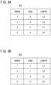
- FIG. 4A is a table 421 illustrating the first order.
- the first column (order) of the table 421 indicates the first order.
- the second column (edge) of the table 421 indicates a name of each edge forming the selected machining shape 241.
- the third column (length) of the table 421 shows the length of each edge forming the selected machining shape 241.
- the selected machining shape 241 includes the edge B, the edge C, and the edge D in this order along the clockwise direction from the first edge A.
- the first order is, for example, the order in which the first edge A, the edge B, the edge C, and the edge D are arranged in this order.
- FIG. 4B is a table 422 illustrating the second order.
- the format of the table 422 is the same as that of the table 421. However, the first column (order) of the table 422 indicates the second order.
- the machining shape 242 includes the edge F, the edge G, and the edge H in this order along the clockwise direction from the second edge E.
- the second order is the order in which the second edge E, the edge F, the edge G, and the edge H are arranged in this order.
- the storage unit 16 stores the contents of the table 421 (first order) and the contents of the table 422 (second order).
- the judgment unit 40 associates the edges (edges B to D) excluding the first edge A of the selected machining shape 241 with the edges (edges F to H) excluding the second edge E of the machining shape 242.
- the comparison judgment unit 40 associates the edges B to D with the edges F to H based on the first order and the second order. For example, the edge B in the second position in the first order is associated with the edge F in the second position in the second order. The edge C in the third position in the first order is associated with the edge G in the third position in the second order. The edge D in the fourth position in the first order is associated with the edge H in the fourth position in the second order.
- the judgment unit 40 calculates the area of the selected machining shape 241 and the area of the machining shape 242. The judgment unit 40 compares the area of the selected machining shape 241 with the area of the machining shape 242.
- the judgment unit 40 judges that the selected machining shape 241 and the machining shape 242 are congruent.
- the group creation unit 28 classifies the machining shape 242 into the same group as the selected machining shape 241.
- the group creation unit 28 determines whether each of the machining shapes 243 to 245 is congruent with the selected machining shape 241 using the order determination unit 38 and the judgment unit 40.
- each of the machining shapes 243 to 245 does not include the second edge having the same length as the first edge A.
- the machining shapes 243 to 245 are not congruent at least with the selected machining shape 241.
- the group creation unit 28 judges whether the machining shapes 243 to 245 are congruent.
- the machining shape 243, the machining shape 244, or the machining shape 245 is newly selected as the selected machining shape 24.
- the description of the process of judging whether the machining shapes 243 to 245 are congruent based on the selected machining shape 24 that was newly selected is substantially a duplicate of the above description and thus will be omitted.
- FIG. 5 is a table 44 illustrating results of grouping the machining shapes 24.
- the first column of the table 44 shows the names of the machining shapes 24.
- the second column of the table 44 indicates a group to which each machining shape 24 belongs.
- the grouping result exemplified in FIG. 5 is obtained by the group creation unit 28 grouping all the machining shapes 24 in the figure data 20.
- the machining shape 241 and the machining shape 242 belong to the same group GA.
- the machining shapes 243, 244, and 245 belong to the same group GB.
- the grouping result is stored in the storage unit 16.
- the figure edit unit 30 includes a first path addition unit (path addition unit) 46 and a second path addition unit (automatic path addition unit) 48.
- the first path addition unit 46 adds a machining start position (first machining start position) 50 and an approach path (first approach path) 52 to the figure data 20 in accordance with an operation of the operator.
- the figure data 20 edited by the first path addition unit 46 is displayed on the display screen 121.
- FIG. 6 is a diagram illustrating the figure data 20 after being edited by the first path addition unit 46.
- the machining start position 50 indicates the initial position of the wire electrode that performs machining along any one of the machining shapes 24.
- any one of the machining shapes 24 is arbitrarily selected by the operator via the operation unit 14.
- the operator selects a machining shape 241 (see FIG. 3 ).
- the machining shape 241 selected by the operator is also referred to as the first machining shape 241 in the following description.
- a hole through which the wire electrode can be inserted is formed at a position of an actual workpiece indicated by the machining start position 50.
- the approach path 52 is a path followed by the wire electrode, connecting the machining start position 50 and the first machining shape 241.
- the second path addition unit 48 identifies the second machining shape 24 belonging to the same group GA as the first machining shape 241 based on the grouping result ( FIG. 5 ).
- the machining shape 242 is identified as the second machining shape 24.
- the second path addition unit 48 automatically edits the figure data 20 as follows based on the result of identifying the second machining shape 242.
- FIG. 7 is a diagram showing the figure data 20 of FIG. 6 after being edited by the second path addition unit 48.
- the second path addition unit 48 automatically adds a machining start position (second machining start position) 56 and an approach path (second approach path) 58 to the figure data 20.
- the machining start position 56 indicates the initial position of the wire electrode for machining the second machining shape 242.
- the approach path 58 is a path leading to the second machining shape 242.
- the approach path 58 connects the machining start position 56 and the second machining shape 242.
- the second path addition unit 48 edits the figure data 20 so that the figure formed by the machining start position 56, the approach path 58, and the second machining shape 242 is congruent with the figure formed by the machining start position 50, the approach path 52, and the first machining shape 241.
- the machining start position 56 and the approach path 58 are automatically added to the figure data 20. Therefore, the operator can easily obtain the figure data 20 including machining start positions and approach paths.
- the figure formed by the machining start position 56, the approach path 58, and the second machining shape 242 is congruent with the figure formed by the machining start position 50, the approach path 52, and the first machining shape 241.
- the figure data 20 can be automatically edited with the content reflecting the intention of the operator.
- the operator sets the machining start position 50 and the approach path 52 to the inside of the first machining shape 241.
- the machining start position 56 and the approach path 58 are set outside the second machining shape 242, the wire electrode cannot perform die machining along the second machining shape 242.
- the figure data editing apparatus 10 (second path addition unit 48) can automatically set the second machining start position 56 to the inside of the second machining shape 242 in accordance with the first machining start position 50 set to the inside of the first machining shape 241.
- the second path addition unit 48 automatically adds to the figure data 20 approach paths connected to each of the machining shapes 244 and 245 belonging to the same group GB as the machining shape 243.
- FIG. 8 is a flowchart illustrating the flow of the figure data edit method according to the embodiment.
- the figure data edit device 10 can execute the figure data edit method of FIG. 8 .
- the figure data edit method of FIG. 8 includes a figure acquisition step S1, a group creation step S2, a first path addition step (path addition step) S3, a second path addition step (automatic path addition step) S4, and an end judgment step (third end judgment step) S5.
- the figure acquisition unit 26 acquires the figure data 20.
- the group creation step S2 includes a decomposition step S21, a selection step S22, a group new-creation step S23, and a search step S24.
- the decomposition step S21 is started after the completion of the figure acquisition step S1.
- the decomposition unit 32 decomposes each of the machining shapes 24 into figure elements (edges).
- the selection unit 34 selects the selected machining shape 24.
- the selection unit 34 selects an ungrouped machining shape 24 as the selected machining shape 24 from among the machining shapes 24 in the figure data 20.
- the group creation unit 28 creates a group to which the selected machining shape 24 belongs. At least the selected machining shape 24 belongs to the created group.
- the search unit 36 searches for a second edge having the same length as the first edge of the selected machining shape 24 among the machining shapes 24 other than the selected machining shape 24. If the second edge is not retrieved (S24: NO), a second termination determination step S29, which will be described later, is executed.
- the group creation step S2 further includes an order determination step S25, a judgment step S26, a group update step S27, a first end judgment step S28, and a second end judgment step S29.
- the order determination step S25 is started when the second edge is retrieved (S24: YES).
- the order determination unit 38 determines the first order and the second order.
- the first order is determined based on the first edge.
- the second order is determined based on the second edge.
- the judgment unit 40 compares the selected machining shape 24 with the machining shape 24 including the second edge based on the first order and the second order. Based on the comparison result, the judgment unit 40 judges whether the selected machining shape 24 and the machining shape 24 including the second edge are congruent.
- the group update step S27 is started when it is determined that the selected machining shape 24 and the machining shape 24 including the second edge are congruent (S26: YES).
- the group creation unit 28 places, in the same group as the selected machining shape 24, the machining shape 24 that is determined to be congruent with the selected machining shape 24.
- the first end judgment step S28 is started when it is judged that the selected machining shape 24 and the machining shape 24 including the second edge are not congruent (S26: NO).
- the judgment unit 40 judges whether there is a machining shape 24 that includes the second edge and has not yet been compared with the selected machining shape 24.
- the judgment step S26 is executed again. That is, if the machining shapes 24 include the second edge, the judgment step S26 is repeated until all the machining shapes 24 including the second edge are compared with the selected machining shape 24.
- the second end judgment step S29 is started when all the machining shapes 24 including the second edge have been compared with the selected machining shape 24 (S28: NO).
- the judgment unit 40 judges whether all the machining shapes 24 in the figure data 20 have been grouped into groups. If there are still ungrouped machining shapes 24 (S29: NO), the selection step S22 is executed again.
- the first path addition step S3 is started when all the machining shapes 24 in the figure data 20 have been grouped (S29: YES) into groups.
- the first path addition unit 46 adds the machining start position 50 and the approach path 52 to the figure data 20 in accordance with the operation of the operator.
- the approach path 52 connects the first machining shape 24 with the machining start position 50.
- the second path addition step S4 is started after the completion of the first path addition step S3.
- the second path addition unit 48 automatically adds the machining start position 56 and the approach path 58 to the figure data 20.
- the approach path 58 connects the second machining shape 24 with the machining start position 56.
- the second machining shape 24 is identified based on the execution result of the group creation step S2 and the execution result of the first path addition step S3.
- the third termination judgment step S5 is started after the completion of the second path addition step S4.
- the second path addition step S4 is executed again.
- the machining start position 56 and the approach path 58 are automatically added to all the machining shapes 24 congruent with the first machining shape 24.
- the operator can easily obtain the figure data 20 with the second machining start position 56 and the approach path 58 added.
- the judgment unit 40 may judge that the machining shape 24 is congruent with the selected machining shape 24 when the machining shape 24 is a mirror image of the selected machining shape 24. In this case, the judgment unit 40 performs a process described next, for example.
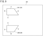
- FIG. 9 is a diagram illustrating figure data 201 according to the first modified example.
- the machining shape 241 in FIG. 9 is the same as the machining shape 241 in FIG. 3 .
- the machining shape 246 in FIG. 9 is formed by an edge U, an edge V, an edge W, and an edge X.
- the length of the edge U is the same as that of the first edge A.
- the edge U is the second edge in the present modified example.
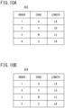
- the order determination unit 38 determines the second order of the machining shape 246 including the second edge U as shown in the table 423.
- the second order of the table 423 is the order of following the edge U, the edge V, the edge W, and the edge X along the machining shape 246 in the same clockwise direction as the first order (see FIG. 4A ).
- the edge B and the edge V correspond to each other based on the first order of the table 421 and the second order of the table 423.
- the edge C and the edge W correspond to each other.
- the edge D and the edge X correspond to each other.
- the order determination unit 38 reverses one of the first order and the second order.
- FIG. 10B is a table 424 showing the order in which the second order in FIG. 10A is reversed.
- the format of the table 424 is the same as that of the table 423.
- the order determination unit 38 reverses, for example, the second order in FIG. 10A as shown in FIG. 10B .
- the second order after the reverse is the order in which the edge U, the edge X, the edge W, and the edge V are followed in the counterclockwise direction along the machining shape 246.
- the judgment unit 40 associates the edges of the selected machining shape 241 with the edges of the machining shape 246 again based on the first order and the second order after the reverse. This makes the edge B and the edge X correspond to each other. Also, the edge C and the edge W correspond to each other. The edge D and the edge V correspond to each other.
- the judgment unit 40 compares the area of the selected machining shape 241 with the area of the machining shape 246. If the area of the selected machining shape 241 is the same as the area of the machining shape 246, then the machining shape 246 is a mirror image of the selected machining shape 241.
- the machining shape (24) may be circular.
- the figure elements may include the diameter of the machining shape.
- the judgment unit 40 may judge whether the diameters of the machining shapes are equal. Two circles of the same diameter are congruent.
- the machining shape (24) may include a curve (arc line).
- the figure elements may include the length of the curve and the curvature of the curve.
- the judgment unit 40 may also judge whether the lengths and curvatures of the curves are equal. Two curves with the same length and curvature are congruent.
- the figure elements regarding the curve (arc) may include a radius of curvature.
- the decision step S26 there is a case where the number of figure elements is different between the selected machining shape (24) and the machining shape (24) in the first place.
- the selected machining shape and the machining shape cannot be congruent.
- the selected machining shape is a polygon
- the selected machining shape has a plurality of line segments (edges).
- the machining shape has only a single curve (closed curve). In other words, the circular shape does not have line segments (edges).
- the judgment unit 40 may judge that the machining shape does not correspond to the selected machining shape when the number of figure elements of the selected machining shape and the number of figure elements of the machining shape are different.
- the group creation unit 28 may divide the machining shapes (24) into groups in each of which shapes are similar to each other.
- the judgment unit 40 associates, for example, edges of one of the two machining shapes with edges of the other machining shape. This correspondence is established based on the order of the edges of each machining shape. However, the judgment unit 40 associates two edges having different lengths with each other.
- the judgment unit 40 calculates a ratio of an edge of one of the two machining shapes to an edge of the other machining shape.
- the ratios are computed as many as the number of pairs of the corresponding two edges. That is, the judgment unit 40 calculates a plurality of ratios. If the ratios are all the same, the two machining shapes described above are similar to each other.
- the method for judging whether two machining shapes are similar to each other is not limited as long as it can judge whether the selected machining shape is similar to the first machining shape.
- the second path addition unit 48 automatically adds to the figure data 20 the approach path 58 and the machining start position 56 leading to the machining shape similar to the selected machining shape.
- the machining shape similar to the selected machining shape and the machining start position 56 are connected by the approach path 58.
- the figure formed by the second machining start position 56, the approach path 58, and the machining shape similar to the selected machining shape is similar to the figure formed by the machining start position 50, the approach path, and the selected machining shape.
- the first path addition unit 46 adds only the first approach path 52 out of the first machining start position 50 and the first approach path 52 to the figure data 20 in accordance with the operator's operation.
- the figure data edit device 10 may be configured integrally with the aforementioned CNC.
- FIG. 11 is a schematic block diagram of a machining program creation device 60 provided with a figure data edit device 10.
- the figure data edit device 10 may be configured integrally with the machining program creation device 60.
- the machining program creation device 60 in FIG. 11 includes the components (see FIG. 1 ) of the figure data edit device 10.
- the machining program creation device 60 further includes an NC creation program 62 and a machining program creation unit 64.
- the NC creation program 62 is a program for causing the machining program creation device 60 to create the machining program 66.
- the machining program 66 is a program for instructing the relative movements of the wire electrode of the wire electric discharge machine with respect to a workpiece.
- the NC creation program 62 is stored in the storage unit 16 of the machining program creation device 60.
- the machining program creation unit 64 creates a machining program 66 based on the figure data 20. Thus, the operator obtains the machining program 66.
- the created machining program 66 may be stored in the storage unit 16. The operator may edit the created machining program 66.
- the present invention is not limited to the above-described embodiment and the modified examples, and various configurations can be adopted without departing from the gist of the present invention.
- the first invention is a figure data edit device (10) for editing figure data (20) indicating a plurality of machining shapes (24) to be machined by a wire electric discharge machine on one workpiece, comprising: a figure acquisition unit (26) that acquires the figure data; a group creation unit (28) that groups the plurality of machining shapes into groups in each of which shapes are congruent or similar to each other; a path addition unit (46) that adds a first approach path (52) leading to a first machining shape (24), which is any one of the plurality of machining shapes, to the figure data in response to an operation of an operator; and an automatic path addition unit (48) that automatically adds a second approach path (58) leading to a second machining shape (24) belonging to the same group as the first machining shape to the figure data so as to be congruent or similar to a figure formed by the first machining shape and the first approach path.
- the path addition unit may add, to the figure data in response to an operation of an operator, a first machining start position (50) for machining the first machining shape and the first approach path connecting the first machining start position and the first machining shape, and the automatic path addition unit may automatically add to the figure data a second machining start position (56) for machining the second machining shape and the second approach path connecting the second machining start position and the second machining shape. This facilitates not only the addition of the approach path but also the addition of the machining start position.
- the group creation unit may include a decomposition unit (32) that decomposes each of the plurality of machining shapes into a plurality of figure elements, and a judgment unit (40) that judges whether or not the plurality of machining shapes are congruent or similar to each other by comparing the plurality of figure elements of each of the plurality of machining shapes. Thus, it is judged at the level of figure elements whether or not the machining shapes are congruent or similar to each other.
- the plurality of the figure elements of each of the plurality of machining shapes may include a plurality of edges forming the machining shape
- the group creation unit may further include a selection unit (34) that selects any one of the plurality of machining shapes, a search unit (36) that searches for a second edge having a same length as a first edge that is any one of the plurality of edges forming the selected machining shape, from among the plurality of edges forming the machining shape other than the selected machining shape, and an order determination unit (38) that determines, based on the first edge, a first order of the plurality of edges forming the selected machining shape, and determines, based on the second edge, a second order of the plurality of edges forming the machining shape including the second edge, the judgment unit may judge whether the selected machining shape and the machining shape including the second edge are congruent, based on the first order and the second order. Thus, it is judged whether the machining shape including the first edge and the machining shape including the second edge are congruent
- the automatic path addition unit may add to the figure data a plurality of the second approach paths leading respectively to the plurality of second machining shapes. This facilitates the editing of figure data including a plurality of second machining shapes.
- the second invention is a machining program creation device (60) including the figure data edit device of the first invention, and a machining program creation unit (64) that creates, based on the figure data a machining program (66) for instructing the relative movement of the wire electrode of the wire electric discharge machine with respect to the workpiece.
- a third invention is a figure data edit method for editing figure data (20) indicating a plurality of machining shapes (24) based on which a wire electric discharge machine machines one workpiece, comprising: a figure acquisition step (S1) that acquires the figure data; a group creation step (S2) that groups the plurality of machining shapes into groups in each of which shapes are congruent or similar to each other; a path addition step (S3) that adds a first approach path (52) leading to a first machining shape (24), which is any one of the plurality of machining shapes, to the figure data in response to an operation of an operator; and an automatic path addition step (S4) that automatically adds a second approach path (58) leading to a second machining shape (24) belonging to the same group as the first machining shape to the figure data so as to be congruent or similar to a figure formed by the first machining shape and the first approach path.
Landscapes
- Engineering & Computer Science (AREA)
- Automation & Control Theory (AREA)
- Physics & Mathematics (AREA)
- Electrochemistry (AREA)
- Chemical Kinetics & Catalysis (AREA)
- Mechanical Engineering (AREA)
- Human Computer Interaction (AREA)
- Manufacturing & Machinery (AREA)
- General Physics & Mathematics (AREA)
- Chemical & Material Sciences (AREA)
- Geometry (AREA)
- Electrical Discharge Machining, Electrochemical Machining, And Combined Machining (AREA)
- Numerical Control (AREA)
Abstract
Description
- The present invention relates to a map-data-editing device (figure data edit device), a processing program creation device (machining program creation device), and a map-data-editing method (figure data edit method) that edits figure data for creating a machining program for a wire electric discharge machine.
- A wire electrode of a wire electric discharge machine moves relative to a workpiece. This relative movement is controlled based on a machining program. The machining program is created based on CAD (Computer Aided Design) data representing a figure of a machining shape. The CAD data includes a plurality of machining shapes followed by the wire electrode.
- However, the machining shapes indicate the shapes of the products produced by the wire electric discharge machine. In other words, the machining shapes do not indicate a machining start position and an approach path. The machining start position is the position where the wire electrode starts relative movements. The approach path is a path (line shape) connecting the machining start position and the machining shape.
- An operator in charge of creating a machining program adds machining start positions and approach paths to figure data according to machining shapes before creating the machining program. The machining program is created based on CAD data to which the machining start positions and the approach paths have been added.
- However, the work of adding the machining start position and the approach path to each of the machining shapes in the figure data many times is a burden for an operator. In this regard,
JP H03-189708 A - Based on the above machining shape copying method, for example, when a machining shape is copied, one may consider copying not only the machining start position but also the approach path.
- However, there is a case where an operator edits figure data that contains machining shapes beforehand. When an approach path has not yet been assigned to each of the machining shapes, the operator performs an operation of adding the approach path to the figure data. Here, the operator does not copy the machining shape. Therefore, the operator has to perform operations of adding the machining start position and the approach path to the machining shape many times.
- The present invention aims to solve the above-mentioned problems.
- The first aspect of the present invention is a figure data edit device for editing figure data indicating a plurality of machining shapes based on which a wire electric discharge machine machines one workpiece, the figure data edit method comprising: a figure acquisition unit that acquires the figure data; a group creation unit that groups the plurality of machining shapes into groups in each of which shapes are congruent or similar to each other; a path addition unit that adds a first approach path leading to a first machining shape, which is any one of the plurality of machining shapes, to the figure data in response to an operation of an operator; and an automatic path addition unit that automatically adds a second approach path leading to a second machining shape belonging to the same group as the first machining shape to the figure data so as to be congruent or similar to a figure formed by the first machining shape and the first approach path.
- A second aspect of the present invention is a machining program creation device including: a figure data edit device according to the first aspect; and a machining program creation unit that creates, based on the figure data, a machining program for instructing a relative movement of a wire electrode of the wire electric discharge machine with respect to the workpiece.
- A third aspect of the present invention is a figure data edit method for editing figure data indicating a plurality of machining shapes based on which a wire electric discharge machine machines one workpiece, comprising: a figure acquisition step that acquires the figure data; a group creation step that groups the plurality of machining shapes into groups in each of which shapes are congruent or similar to each other; a path addition step that adds a first approach path leading to a first machining shape, which is any one of the plurality of machining shapes, to the figure data in response to an operation of an operator; and an automatic path addition step that automatically adds a second approach path leading to a second machining shape belonging to the same group as the first machining shape to the figure data so as to be congruent or similar to a figure formed by the first machining shape and the first approach path.
- According to the present invention, it is easy to add approach paths to machining shapes included in the figure data.
-
-
FIG. 1 is a schematic block diagram of a figure data edit device according to an embodiment; -
FIG. 2 is a diagram illustrating figures displayed on a display screen based on figure data; -
FIG. 3 is a diagram illustrating edges of each of machining shapes; -
FIG. 4A is a table illustrating a first order; -
FIG. 4B is a table illustrating a second order; -
FIG. 5 is a table illustrating a result of grouping machining shapes; -
FIG. 6 is a diagram illustrating figure data after a first path addition unit edits the figure data; -
FIG. 7 is a diagram showing figure data ofFIG. 6 after a second path addition unit edits the figure data; -
FIG. 8 is a flowchart illustrating a flow of a figure data edit method according to an embodiment; -
FIG. 9 is a diagram illustrating figure data according to a first modification; -
FIG. 10A is a table illustrating a second order according to a first modified example;FIG. 10B is a table showing the order in which the second order inFIG. 10A has been reversed; and -
FIG. 11 is a schematic block diagram of a machining program creation device including a figure data edit device. -
FIG. 1 is a schematic block diagram of a figuredata edit device 10 according to an embodiment. - The figure
data edit device 10 is an electronic device (computer) including adisplay unit 12, anoperation unit 14, astorage unit 16, and anarithmetic unit 18. - The
display unit 12 is a display device having adisplay screen 121. Information is displayed on thedisplay screen 121 as appropriate. The material of thedisplay unit 12 includes liquid crystals. However, the material of thedisplay unit 12 is not limited to liquid crystals. For example, the material of thedisplay unit 12 may include OEL (Organic Electro-Luminescence). - The
operation unit 14 is an input device that accepts information input by an operator. Theoperation unit 14 includes, for example, a mouse, a keyboard, and a touch pad. Theoperation unit 14 may include a touch panel. In this case, the touch panel is attached to thedisplay screen 121. - The
storage unit 16 has one or more memories. For example, thestorage unit 16 includes a R_AM (Random Access Memory) and a ROM (Read Only Memory). Thestorage unit 16 stores figuredata 20 and anedit program 22. -
FIG. 2 is a diagram illustrating figures displayed on thedisplay screen 121 based on thefigure data 20. - The
figure data 20 is data representingmachining shapes 24. Thefigure data 20 is a data file created using, for example, a CAD system. - The
machining shape 24 indicates a shape to be machined by the wire electric discharge machine. Thefigure data 20 inFIG. 2 includesmachining shapes 24 to be machined by the wire electric discharge machine for one workpiece. Thefigure data 20 inFIG. 2 includes five machining shapes 24 (241, 242, 243, 244, 245) for illustrative purposes. - Each of the machining shapes 24 is in the form of a loop. To this extent, the shape of the
machining shape 24 is not limited. Each of the machining shapes 24 illustrated inFIG. 2 is a trapezoid (polygon). - The
edit program 22 is a program for causing the figuredata edit device 10 to execute the figure data edit method of the present embodiment. The figure data edit method will be described later. - The
arithmetic unit 18 has one or more processors. For example, thearithmetic unit 18 includes a CPU (Central Processing Unit) and a GPU (Graphics Processing Unit). Thearithmetic unit 18 can refer to the information stored in thestorage unit 16 as appropriate. - The
arithmetic unit 18 includes afigure acquisition unit 26, agroup creation unit 28, and afigure edit unit 30. Thefigure acquisition unit 26, thegroup creation unit 28, and thefigure edit unit 30 are realized by thearithmetic unit 18 executing theedit program 22. - The
figure acquisition unit 26 acquires thefigure data 20. Thefigure acquisition unit 26 acquires thefigure data 20 by referring to thestorage unit 16. - However, the
figure acquisition unit 26 may acquire thefigure data 20 from an external device of the figuredata edit device 10 by communicating with the external device. In this case, the figuredata edit device 10 and the external device are communicably connected. The external device of the figuredata edit device 10 is, for example, a computer such as a computerized numerical controller (CNC) that controls the wire electric discharge machine. Thefigure acquisition unit 26 may acquire thefigure data 20 from a removable external storage medium such as a USB (Universal Serial Bus) memory. - The
group creation unit 28 divides the machining shapes 24 indicated by thefigure data 20 into groups in each of which shapes are congruent with each other. To perform this grouping, thegroup creation unit 28 includes adecomposition unit 32, aselection unit 34, asearch unit 36, anorder determination unit 38, and ajudgment unit 40. - The
decomposition unit 32 decomposes each of the machining shapes 24 into figure elements. The figure elements are, for example, line segments (edges). -
FIG. 3 is a diagram illustrating edges of each of machining shapes 24. - For example, the
machining shape 241 is a trapezoid (polygon) formed by four edges, namely, an edge A, an edge B, an edge C, and an edge D. Therefore, thedecomposition unit 32 decomposes themachining shape 241 into the edge A, the edge B, the edge C, and the edge D. - Similarly, the
machining shape 242 is decomposed into an edge E, an edge F, an edge G, and an edge H. Themachining shape 243 is decomposed into an edge I, an edge J, an edge K, and an edge L. Themachining shape 244 is decomposed into an edge M, an edge N, an edge O, and an edge P. Themachining shape 245 is decomposed into an edge Q, an edge R, an edge S, and an edge T. The decomposition results (edges of the machining shapes 24) are stored in thestorage unit 16. - The
selection unit 34 selects oneungrouped machining shape 24 from the machining shapes 24. When there are a plurality of ungrouped machining shapes 24, theselection unit 34 may randomly select one from the ungrouped machining shapes 24. When there are a plurality of ungrouped machining shapes 24, theselection unit 34 may select one based on a predetermined rule. - Here, for the sake of illustration, the
selection unit 34 selects themachining shape 241. Themachining shape 241 selected by theselection unit 34 is also referred to as a selectedmachining shape 241 in the following description. - The
search unit 36 selects one of the edges (edges A to D) forming the selectedmachining shape 241. Thesearch unit 36 may randomly select any one of the edges from the selectedmachining shape 241. Theselection unit 34 may select any one of the edges of the selectedmachining shape 241 based on a predetermined rule. - Here, for the sake of illustration, the
search unit 36 selects the edge A. The edge A selected by thesearch unit 36 from the selectedmachining shape 241 is also referred to as a first edge A in the following description. - The
machining shape 24 congruent with the selectedmachining shape 241 necessarily includes one second edge having the same length as the first edge A. Based on this, thesearch unit 36 searches for the second edge (the edge with the same length as the first edge A) among each of the machining shapes 242 to 245 other than the selectedmachining shape 241. Thus, themachining shape 24 that can be congruent with the selectedmachining shape 241 is identified. - Here, for the sake of illustration, only the edge E of the
machining shape 242 is the edge with the same length as the first edge A. The edge E is also referred to as the second edge E in the following description. - The
order determination unit 38 determines the order (first order) of the edges of the selectedmachining shape 241 and the order (second order) of the edges of themachining shape 242 including the second edge E. - The first order is determined based on the first edge A and a predetermined cyclic direction. The predetermined cyclic direction is a right-handed (clockwise) direction or a left-handed (counterclockwise) direction. For the sake of illustration, the predetermined cyclic direction is the clockwise direction.
-
FIG. 4A is a table 421 illustrating the first order. The first column (order) of the table 421 indicates the first order. The second column (edge) of the table 421 indicates a name of each edge forming the selectedmachining shape 241. The third column (length) of the table 421 shows the length of each edge forming the selectedmachining shape 241. - The selected
machining shape 241 includes the edge B, the edge C, and the edge D in this order along the clockwise direction from the first edge A. In this case, the first order is, for example, the order in which the first edge A, the edge B, the edge C, and the edge D are arranged in this order. -
FIG. 4B is a table 422 illustrating the second order. The format of the table 422 is the same as that of the table 421. However, the first column (order) of the table 422 indicates the second order. - The
machining shape 242 includes the edge F, the edge G, and the edge H in this order along the clockwise direction from the second edge E. In this case, the second order is the order in which the second edge E, the edge F, the edge G, and the edge H are arranged in this order. - The
storage unit 16 stores the contents of the table 421 (first order) and the contents of the table 422 (second order). - The
judgment unit 40 associates the edges (edges B to D) excluding the first edge A of the selectedmachining shape 241 with the edges (edges F to H) excluding the second edge E of themachining shape 242. - The
comparison judgment unit 40 associates the edges B to D with the edges F to H based on the first order and the second order. For example, the edge B in the second position in the first order is associated with the edge F in the second position in the second order. The edge C in the third position in the first order is associated with the edge G in the third position in the second order. The edge D in the fourth position in the first order is associated with the edge H in the fourth position in the second order. - The
comparison judgment unit 40 judges whether the edges B to D of the selectedmachining shape 241 and the edges corresponding to the edges B to D among the edges F to H of themachining shape 242 are the same length. That is, thejudgment unit 40 judges whether (1) the length of the edge B = the length of the edge F, (2) the length of the edge C = the length of the edge G, and (3) the length of the edge D = the length of the edge H. - When the edges B to D of the selected
machining shape 241 and the edges corresponding to the edges B to D among the edges F to H of themachining shape 242 are the same length, thejudgment unit 40 calculates the area of the selectedmachining shape 241 and the area of themachining shape 242. Thejudgment unit 40 compares the area of the selectedmachining shape 241 with the area of themachining shape 242. - When the area of the selected
machining shape 241 and the area of themachining shape 242 are the same, thejudgment unit 40 judges that the selectedmachining shape 241 and themachining shape 242 are congruent. When it is determined that the selectedmachining shape 241 and themachining shape 242 are congruent, thegroup creation unit 28 classifies themachining shape 242 into the same group as the selectedmachining shape 241. - If each of the machining shapes 243 to 245 also includes the second edge, the
group creation unit 28 determines whether each of the machining shapes 243 to 245 is congruent with the selectedmachining shape 241 using theorder determination unit 38 and thejudgment unit 40. - However, as described above, each of the machining shapes 243 to 245 does not include the second edge having the same length as the first edge A. Thus, the machining shapes 243 to 245 are not congruent at least with the selected
machining shape 241. - In this case, the
group creation unit 28 judges whether the machining shapes 243 to 245 are congruent. In this case, themachining shape 243, themachining shape 244, or themachining shape 245 is newly selected as the selectedmachining shape 24. The description of the process of judging whether the machining shapes 243 to 245 are congruent based on the selectedmachining shape 24 that was newly selected is substantially a duplicate of the above description and thus will be omitted. -
FIG. 5 is a table 44 illustrating results of grouping the machining shapes 24. The first column of the table 44 shows the names of the machining shapes 24. The second column of the table 44 indicates a group to which eachmachining shape 24 belongs. - The grouping result exemplified in
FIG. 5 , for example, is obtained by thegroup creation unit 28 grouping all the machining shapes 24 in thefigure data 20. According toFIG. 5 , themachining shape 241 and themachining shape 242 belong to the same group GA. Further, the machining shapes 243, 244, and 245 belong to the same group GB. The grouping result is stored in thestorage unit 16. - The
figure edit unit 30 includes a first path addition unit (path addition unit) 46 and a second path addition unit (automatic path addition unit) 48. - The first
path addition unit 46 adds a machining start position (first machining start position) 50 and an approach path (first approach path) 52 to thefigure data 20 in accordance with an operation of the operator. Thefigure data 20 edited by the firstpath addition unit 46 is displayed on thedisplay screen 121. -
FIG. 6 is a diagram illustrating thefigure data 20 after being edited by the firstpath addition unit 46. - The
machining start position 50 indicates the initial position of the wire electrode that performs machining along any one of the machining shapes 24. Here, any one of the machining shapes 24 is arbitrarily selected by the operator via theoperation unit 14. - Here, for the sake of illustration, the operator selects a machining shape 241 (see
FIG. 3 ). Themachining shape 241 selected by the operator is also referred to as thefirst machining shape 241 in the following description. A hole through which the wire electrode can be inserted is formed at a position of an actual workpiece indicated by themachining start position 50. - The
approach path 52 is a path followed by the wire electrode, connecting themachining start position 50 and thefirst machining shape 241. - When the
approach path 52 leading to thefirst machining shape 241 is assigned to thefigure data 20, the secondpath addition unit 48 identifies thesecond machining shape 24 belonging to the same group GA as thefirst machining shape 241 based on the grouping result (FIG. 5 ). Here, only themachining shape 242 is identified as thesecond machining shape 24. - The second
path addition unit 48 automatically edits thefigure data 20 as follows based on the result of identifying thesecond machining shape 242. -
FIG. 7 is a diagram showing thefigure data 20 ofFIG. 6 after being edited by the secondpath addition unit 48. - The second
path addition unit 48 automatically adds a machining start position (second machining start position) 56 and an approach path (second approach path) 58 to thefigure data 20. Themachining start position 56 indicates the initial position of the wire electrode for machining thesecond machining shape 242. Theapproach path 58 is a path leading to thesecond machining shape 242. Theapproach path 58 connects themachining start position 56 and thesecond machining shape 242. Thus, the operator can easily obtain thefigure data 20 including themachining start position 56 and theapproach path 58. - Here, the second
path addition unit 48 edits thefigure data 20 so that the figure formed by themachining start position 56, theapproach path 58, and thesecond machining shape 242 is congruent with the figure formed by themachining start position 50, theapproach path 52, and thefirst machining shape 241. - According to the figure
data edit device 10, themachining start position 56 and theapproach path 58 are automatically added to thefigure data 20. Therefore, the operator can easily obtain thefigure data 20 including machining start positions and approach paths. - Moreover, the figure formed by the
machining start position 56, theapproach path 58, and thesecond machining shape 242 is congruent with the figure formed by themachining start position 50, theapproach path 52, and thefirst machining shape 241. Thus, thefigure data 20 can be automatically edited with the content reflecting the intention of the operator. - For example, when the
figure data 20 is for die machining, the operator sets themachining start position 50 and theapproach path 52 to the inside of thefirst machining shape 241. Here, if themachining start position 56 and theapproach path 58 are set outside thesecond machining shape 242, the wire electrode cannot perform die machining along thesecond machining shape 242. - In this regard, the figure data editing apparatus 10 (second path addition unit 48) can automatically set the second
machining start position 56 to the inside of thesecond machining shape 242 in accordance with the firstmachining start position 50 set to the inside of thefirst machining shape 241. - It is assumed that the operator assigns to the
figure data 20 an approach path leading to themachining shape 243. In this case, the secondpath addition unit 48 automatically adds to thefigure data 20 approach paths connected to each of the machining shapes 244 and 245 belonging to the same group GB as themachining shape 243. -
FIG. 8 is a flowchart illustrating the flow of the figure data edit method according to the embodiment. - The figure
data edit device 10 can execute the figure data edit method ofFIG. 8 . The figure data edit method ofFIG. 8 includes a figure acquisition step S1, a group creation step S2, a first path addition step (path addition step) S3, a second path addition step (automatic path addition step) S4, and an end judgment step (third end judgment step) S5. - In the figure acquisition step S1, the
figure acquisition unit 26 acquires thefigure data 20. - The group creation step S2 includes a decomposition step S21, a selection step S22, a group new-creation step S23, and a search step S24.
- The decomposition step S21 is started after the completion of the figure acquisition step S1. In the decomposition step S21, the
decomposition unit 32 decomposes each of the machining shapes 24 into figure elements (edges). - In the selection step S22, the
selection unit 34 selects the selectedmachining shape 24. Theselection unit 34 selects anungrouped machining shape 24 as the selectedmachining shape 24 from among the machining shapes 24 in thefigure data 20. - In the group new-creation step S23, the
group creation unit 28 creates a group to which the selectedmachining shape 24 belongs. At least the selectedmachining shape 24 belongs to the created group. - In the search step S24, the
search unit 36 searches for a second edge having the same length as the first edge of the selectedmachining shape 24 among the machining shapes 24 other than the selectedmachining shape 24. If the second edge is not retrieved (S24: NO), a second termination determination step S29, which will be described later, is executed. - The group creation step S2 further includes an order determination step S25, a judgment step S26, a group update step S27, a first end judgment step S28, and a second end judgment step S29.
- The order determination step S25 is started when the second edge is retrieved (S24: YES). In the order determination step S25, the
order determination unit 38 determines the first order and the second order. The first order is determined based on the first edge. The second order is determined based on the second edge. - In the judgment step S26, the
judgment unit 40 compares the selectedmachining shape 24 with themachining shape 24 including the second edge based on the first order and the second order. Based on the comparison result, thejudgment unit 40 judges whether the selectedmachining shape 24 and themachining shape 24 including the second edge are congruent. - The group update step S27 is started when it is determined that the selected
machining shape 24 and themachining shape 24 including the second edge are congruent (S26: YES). In the group update step S27, thegroup creation unit 28 places, in the same group as the selectedmachining shape 24, themachining shape 24 that is determined to be congruent with the selectedmachining shape 24. - The first end judgment step S28 is started when it is judged that the selected
machining shape 24 and themachining shape 24 including the second edge are not congruent (S26: NO). In the first end judgment step S28, thejudgment unit 40 judges whether there is amachining shape 24 that includes the second edge and has not yet been compared with the selectedmachining shape 24. - If there is a
machining shape 24 that includes the second edge and has not yet been compared with the selected machining shape 24 (S28: YES), the judgment step S26 is executed again. That is, if the machining shapes 24 include the second edge, the judgment step S26 is repeated until all the machining shapes 24 including the second edge are compared with the selectedmachining shape 24. - The second end judgment step S29 is started when all the machining shapes 24 including the second edge have been compared with the selected machining shape 24 (S28: NO). In the second end judgment step S29, the
judgment unit 40 judges whether all the machining shapes 24 in thefigure data 20 have been grouped into groups. If there are still ungrouped machining shapes 24 (S29: NO), the selection step S22 is executed again. - The first path addition step S3 is started when all the machining shapes 24 in the
figure data 20 have been grouped (S29: YES) into groups. In the first path addition step S3, the firstpath addition unit 46 adds themachining start position 50 and theapproach path 52 to thefigure data 20 in accordance with the operation of the operator. Theapproach path 52 connects thefirst machining shape 24 with themachining start position 50. - The second path addition step S4 is started after the completion of the first path addition step S3. In the second path addition step S4, the second
path addition unit 48 automatically adds themachining start position 56 and theapproach path 58 to thefigure data 20. Theapproach path 58 connects thesecond machining shape 24 with themachining start position 56. Thesecond machining shape 24 is identified based on the execution result of the group creation step S2 and the execution result of the first path addition step S3. - The third termination judgment step S5 is started after the completion of the second path addition step S4. In the third end judgment step S5, it is judged whether the
approach paths 58 and the machining start positions 56 corresponding to all the second machining shapes 24 have been added to thefigure data 20. This judgment is performed by, for example, the secondpath addition unit 48. - If there remains the
second machining shape 24 that is not connected to themachining start position 56 and the approach path 58 (S5: NO), the second path addition step S4 is executed again. Thus, themachining start position 56 and theapproach path 58 are automatically added to all the machining shapes 24 congruent with thefirst machining shape 24. - According to the above described figure data edit method, the operator can easily obtain the
figure data 20 with the secondmachining start position 56 and theapproach path 58 added. - In the following, modified examples of the above embodiment will be described. However, the description overlapping with the above embodiment will be omitted in the following description as much as possible. Components already described in the above embodiment are given the same reference numerals as in the above embodiment unless otherwise noted.
- The
judgment unit 40 may judge that themachining shape 24 is congruent with the selectedmachining shape 24 when themachining shape 24 is a mirror image of the selectedmachining shape 24. In this case, thejudgment unit 40 performs a process described next, for example. -
FIG. 9 is a diagram illustratingfigure data 201 according to the first modified example. - The
machining shape 241 inFIG. 9 is the same as themachining shape 241 inFIG. 3 . Themachining shape 246 inFIG. 9 is formed by an edge U, an edge V, an edge W, and an edge X. -
FIG. 10A is a table 423 illustrating a second order according to a first modified example. The format of the table 423 is the same as that of the table 422. - As a result of the search performed by the
search unit 36, the length of the edge U is the same as that of the first edge A. In other words, the edge U is the second edge in the present modified example. Theorder determination unit 38 determines the second order of themachining shape 246 including the second edge U as shown in the table 423. - The second order of the table 423 is the order of following the edge U, the edge V, the edge W, and the edge X along the
machining shape 246 in the same clockwise direction as the first order (seeFIG. 4A ). In this case, the edge B and the edge V correspond to each other based on the first order of the table 421 and the second order of the table 423. Also, the edge C and the edge W correspond to each other. The edge D and the edge X correspond to each other. - However, in this example, at least the length (LB) of the edge B and the length (LD) of the edge V are different. In this case, the
order determination unit 38 reverses one of the first order and the second order. -
FIG. 10B is a table 424 showing the order in which the second order inFIG. 10A is reversed. The format of the table 424 is the same as that of the table 423. - The
order determination unit 38 reverses, for example, the second order inFIG. 10A as shown inFIG. 10B . The second order after the reverse is the order in which the edge U, the edge X, the edge W, and the edge V are followed in the counterclockwise direction along themachining shape 246. - The
judgment unit 40 associates the edges of the selectedmachining shape 241 with the edges of themachining shape 246 again based on the first order and the second order after the reverse. This makes the edge B and the edge X correspond to each other. Also, the edge C and the edge W correspond to each other. The edge D and the edge V correspond to each other. - The
judgment unit 40 compares the lengths of the two corresponding edges again. That is, thejudgment unit 40 determines whether or not (4) the length of the edge B = the length of the edge X, (5) the length of the edge C = the length of the edge W, and (6) the length of the edge D = the length of the edge V hold. - When all of (4) to (6) hold, the
judgment unit 40 compares the area of the selectedmachining shape 241 with the area of themachining shape 246. If the area of the selectedmachining shape 241 is the same as the area of themachining shape 246, then themachining shape 246 is a mirror image of the selectedmachining shape 241. - The machining shape (24) may be circular. In this case, the figure elements may include the diameter of the machining shape. When the plurality of machining shapes have a circular shape, the
judgment unit 40 may judge whether the diameters of the machining shapes are equal. Two circles of the same diameter are congruent. - In addition, the machining shape (24) may include a curve (arc line). In this case, the figure elements may include the length of the curve and the curvature of the curve. The
judgment unit 40 may also judge whether the lengths and curvatures of the curves are equal. Two curves with the same length and curvature are congruent. The figure elements regarding the curve (arc) may include a radius of curvature. - In addition, regarding the decision step S26, there is a case where the number of figure elements is different between the selected machining shape (24) and the machining shape (24) in the first place. In this case, the selected machining shape and the machining shape cannot be congruent. For example, when the selected machining shape is a polygon, the selected machining shape has a plurality of line segments (edges). In contrast, for example, when the machining shape is circular, the machining shape has only a single curve (closed curve). In other words, the circular shape does not have line segments (edges). Based on the above, the
judgment unit 40 may judge that the machining shape does not correspond to the selected machining shape when the number of figure elements of the selected machining shape and the number of figure elements of the machining shape are different. - The
group creation unit 28 may divide the machining shapes (24) into groups in each of which shapes are similar to each other. - To judge whether two machining shapes are similar to each other, the
judgment unit 40 associates, for example, edges of one of the two machining shapes with edges of the other machining shape. This correspondence is established based on the order of the edges of each machining shape. However, thejudgment unit 40 associates two edges having different lengths with each other. - The
judgment unit 40 calculates a ratio of an edge of one of the two machining shapes to an edge of the other machining shape. The ratios are computed as many as the number of pairs of the corresponding two edges. That is, thejudgment unit 40 calculates a plurality of ratios. If the ratios are all the same, the two machining shapes described above are similar to each other. - The method for judging whether two machining shapes are similar to each other is not limited as long as it can judge whether the selected machining shape is similar to the first machining shape.
- The second
path addition unit 48 automatically adds to thefigure data 20 theapproach path 58 and themachining start position 56 leading to the machining shape similar to the selected machining shape. The machining shape similar to the selected machining shape and themachining start position 56 are connected by theapproach path 58. - The figure formed by the second
machining start position 56, theapproach path 58, and the machining shape similar to the selected machining shape is similar to the figure formed by themachining start position 50, the approach path, and the selected machining shape. - There is a situation where at the time when the
figure acquisition unit 26 acquires thefigure data 20, the firstmachining start position 50 has already been added to thefirst machining shape 24. In this case, the firstpath addition unit 46 adds only thefirst approach path 52 out of the firstmachining start position 50 and thefirst approach path 52 to thefigure data 20 in accordance with the operator's operation. - The figure
data edit device 10 may be configured integrally with the aforementioned CNC. -
FIG. 11 is a schematic block diagram of a machiningprogram creation device 60 provided with a figuredata edit device 10. - The figure
data edit device 10 may be configured integrally with the machiningprogram creation device 60. The machiningprogram creation device 60 inFIG. 11 includes the components (seeFIG. 1 ) of the figuredata edit device 10. - The machining
program creation device 60 further includes anNC creation program 62 and a machiningprogram creation unit 64. - The
NC creation program 62 is a program for causing the machiningprogram creation device 60 to create themachining program 66. Themachining program 66 is a program for instructing the relative movements of the wire electrode of the wire electric discharge machine with respect to a workpiece. TheNC creation program 62 is stored in thestorage unit 16 of the machiningprogram creation device 60. - The machining
program creation unit 64 creates amachining program 66 based on thefigure data 20. Thus, the operator obtains themachining program 66. The createdmachining program 66 may be stored in thestorage unit 16. The operator may edit the createdmachining program 66. - The present invention is not limited to the above-described embodiment and the modified examples, and various configurations can be adopted without departing from the gist of the present invention.
- The invention that can be understood from the above embodiment and the modified example will be described below.
- The first invention is a figure data edit device (10) for editing figure data (20) indicating a plurality of machining shapes (24) to be machined by a wire electric discharge machine on one workpiece, comprising: a figure acquisition unit (26) that acquires the figure data; a group creation unit (28) that groups the plurality of machining shapes into groups in each of which shapes are congruent or similar to each other; a path addition unit (46) that adds a first approach path (52) leading to a first machining shape (24), which is any one of the plurality of machining shapes, to the figure data in response to an operation of an operator; and an automatic path addition unit (48) that automatically adds a second approach path (58) leading to a second machining shape (24) belonging to the same group as the first machining shape to the figure data so as to be congruent or similar to a figure formed by the first machining shape and the first approach path.
- This facilitates the editing of figure data that represents machining shapes.
- The path addition unit may add, to the figure data in response to an operation of an operator, a first machining start position (50) for machining the first machining shape and the first approach path connecting the first machining start position and the first machining shape, and the automatic path addition unit may automatically add to the figure data a second machining start position (56) for machining the second machining shape and the second approach path connecting the second machining start position and the second machining shape. This facilitates not only the addition of the approach path but also the addition of the machining start position.
- The group creation unit may include a decomposition unit (32) that decomposes each of the plurality of machining shapes into a plurality of figure elements, and a judgment unit (40) that judges whether or not the plurality of machining shapes are congruent or similar to each other by comparing the plurality of figure elements of each of the plurality of machining shapes. Thus, it is judged at the level of figure elements whether or not the machining shapes are congruent or similar to each other.
- The plurality of the figure elements of each of the plurality of machining shapes may include a plurality of edges forming the machining shape, and the group creation unit may further include a selection unit (34) that selects any one of the plurality of machining shapes, a search unit (36) that searches for a second edge having a same length as a first edge that is any one of the plurality of edges forming the selected machining shape, from among the plurality of edges forming the machining shape other than the selected machining shape, and an order determination unit (38) that determines, based on the first edge, a first order of the plurality of edges forming the selected machining shape, and determines, based on the second edge, a second order of the plurality of edges forming the machining shape including the second edge, the judgment unit may judge whether the selected machining shape and the machining shape including the second edge are congruent, based on the first order and the second order. Thus, it is judged whether the machining shape including the first edge and the machining shape including the second edge are congruent, regardless of the respective inclinations of the machining shape including the first edge and the machining shape including the second edge.
- When there are a plurality of the second machining shapes, the automatic path addition unit may add to the figure data a plurality of the second approach paths leading respectively to the plurality of second machining shapes. This facilitates the editing of figure data including a plurality of second machining shapes.
- The second invention is a machining program creation device (60) including the figure data edit device of the first invention, and a machining program creation unit (64) that creates, based on the figure data a machining program (66) for instructing the relative movement of the wire electrode of the wire electric discharge machine with respect to the workpiece.
- This facilitates the editing of figure data that represents machining shapes. Moreover, a machining program is created based on the edited figure data.
- A third invention is a figure data edit method for editing figure data (20) indicating a plurality of machining shapes (24) based on which a wire electric discharge machine machines one workpiece, comprising: a figure acquisition step (S1) that acquires the figure data; a group creation step (S2) that groups the plurality of machining shapes into groups in each of which shapes are congruent or similar to each other; a path addition step (S3) that adds a first approach path (52) leading to a first machining shape (24), which is any one of the plurality of machining shapes, to the figure data in response to an operation of an operator; and an automatic path addition step (S4) that automatically adds a second approach path (58) leading to a second machining shape (24) belonging to the same group as the first machining shape to the figure data so as to be congruent or similar to a figure formed by the first machining shape and the first approach path.
- This facilitates the editing of figure data that represents machining shapes.
-
- 10: figure data edit device
- 20, 201: figure data
- 24: machining shape
- 26: figure acquisition unit
- 28: group creation unit
- 32: decomposition unit
- 34: selection unit
- 36: search unit
- 38: order determination unit
- 40: judgment unit
- 46: route addition unit
- 48: automatic route addition unit
- 50: first machining start position
- 52: first approach path
- 56: second machining start position
- 58: second approach path
- 60: machining program creation device
- 64: machining program creation unit
- 66: machining program
Claims (7)
- A figure data edit device (10) for editing figure data (20) indicating a plurality of machining shapes (24) based on which a wire electric discharge machine machines one workpiece, the figure data edit device comprising:a figure acquisition unit (26) configured to acquire the figure data;a group creation unit (28) configured to group the plurality of machining shapes into groups in each of which shapes are congruent or similar to each other;a path addition unit (46) configured to add a first approach path (52) leading to a first machining shape (24), which is any one of the plurality of machining shapes, to the figure data in response to an operation of an operator; andan automatic path addition unit (48) configured to automatically add a second approach path (58) leading to a second machining shape (24) belonging to a same group as the first machining shape, to the figure data in a manner so that a resultant figure is congruent or similar to a figure formed by the first machining shape and the first approach path.
- The figure data edit device according to claim 1, whereinthe path addition unit adds a first machining start position (50) for machining the first machining shape and the first approach path connecting the first machining start position and the first machining shape, to the figure data in response to an operation of an operator, andthe automatic path addition unit automatically adds, to the figure data, a second machining start position (56) for machining the second machining shape and the second approach path connecting the second machining start position and the second machining shape.
- The figure data edit device according to claim 1 or 2, wherein
the group creation unit includes:a decomposition unit (32) configured to decompose each of the plurality of machining shapes into a plurality of figure elements; anda judgment unit (40) configured to judge whether or not the plurality of machining shapes are congruent or similar to each other by comparing the plurality of figure elements of each of the plurality of machining shapes. - The figure data edit device according to claim 3, whereinthe plurality of figure elements of each of the plurality of machining shapes include a plurality of edges forming the machining shape,the group creation unit includes:a selection unit (34) configured to select any one of the plurality of machining shapes;a search unit (36) configured to search for a second edge having a same length as a first edge that is any one of the plurality of edges forming the selected machining shape, from among the plurality of edges forming the machining shape other than the selected machining shape; andan order determination unit (38) configured to determine, based on the first edge, a first order of the plurality of edges forming the selected machining shape, and determine, based on the second edge, a second order of the plurality of edges forming the machining shape including the second edge, andthe judgment unit judges whether the selected machining shape and the machining shape including the second edge are congruent, based on the first order and the second order.
- The figure data edit device according to any one of claims 1 to 4, wherein
when there are a plurality of the second machining shapes, the automatic path addition unit adds, to the figure data, a plurality of the second approach paths leading respectively to the plurality of second machining shapes. - A machining program creation device (60) comprising:the figure data edit device according to any one of claims 1 to 5; anda machining program creation unit (64) configured to create, based on the figure data, a machining program (66) for instructing a relative movement of a wire electrode of the wire electric discharge machine with respect to the workpiece.
- A figure data edit method for editing figure data (20) indicating a plurality of machining shapes (24) based on which a wire electric discharge machine machines one workpiece, the figure data edit method comprising:a figure acquisition step (S1) of acquiring the figure data;a group creation step (S2) of grouping the plurality of machining shapes into groups in each of which shapes are congruent or similar to each other;a path addition step (S3) of adding a first approach path (52) leading to a first machining shape (24), which is any one of the plurality of machining shapes, to the figure data in response to an operation of an operator; andan automatic path addition step (S4) of automatically adding a second approach path (58) leading to a second machining shape (24) belonging to a same group as the first machining shape, to the figure data in a manner so that a resultant figure is congruent or similar to a figure formed by the first machining shape and the first approach path.
Applications Claiming Priority (1)
| Application Number | Priority Date | Filing Date | Title |
|---|---|---|---|
| PCT/JP2021/046281 WO2023112207A1 (en) | 2021-12-15 | 2021-12-15 | Map-data-editing device, processing program creation device, and map-data-editing method |
Publications (2)
| Publication Number | Publication Date |
|---|---|
| EP4431214A1 true EP4431214A1 (en) | 2024-09-18 |
| EP4431214A4 EP4431214A4 (en) | 2025-10-08 |
Family
ID=86773836
Family Applications (1)
| Application Number | Title | Priority Date | Filing Date |
|---|---|---|---|
| EP21968123.6A Pending EP4431214A4 (en) | 2021-12-15 | 2021-12-15 | Map data editing device, processing program generation device, and map data editing method |
Country Status (4)
| Country | Link |
|---|---|
| EP (1) | EP4431214A4 (en) |
| JP (1) | JP7614401B2 (en) |
| CN (1) | CN118354860A (en) |
| WO (1) | WO2023112207A1 (en) |
Family Cites Families (8)
| Publication number | Priority date | Publication date | Assignee | Title |
|---|---|---|---|---|
| JPH07104701B2 (en) * | 1989-05-08 | 1995-11-13 | 三菱電機株式会社 | CAD / CAM device |
| JPH03189708A (en) | 1989-12-19 | 1991-08-19 | Fanuc Ltd | Working shape copying method in cad/cam system for metalling mold |
| JP2933979B2 (en) * | 1990-05-16 | 1999-08-16 | 株式会社アマダ | Automatic programming device |
| JP2985569B2 (en) * | 1993-04-23 | 1999-12-06 | 三菱電機株式会社 | NC data creation method for wire electric discharge machining |
| JP2991006B2 (en) * | 1993-07-23 | 1999-12-20 | 三菱電機株式会社 | CAD / CAM equipment |
| JP3117421B2 (en) * | 1997-07-24 | 2000-12-11 | ファナック株式会社 | Coreless machining shape discrimination method and apparatus, and computer-readable recording medium recording coreless machining shape discrimination program |
| JP2000141135A (en) | 1998-11-13 | 2000-05-23 | Okuma Corp | EDM control device |
| JP4353689B2 (en) * | 2002-10-25 | 2009-10-28 | 三菱電機メカトロニクスソフトウエア株式会社 | Method of creating machining path information in CAD / CAM apparatus and CAD / CAM apparatus |
-
2021
- 2021-12-15 WO PCT/JP2021/046281 patent/WO2023112207A1/en not_active Ceased
- 2021-12-15 CN CN202180104836.4A patent/CN118354860A/en active Pending
- 2021-12-15 EP EP21968123.6A patent/EP4431214A4/en active Pending
- 2021-12-15 JP JP2023567391A patent/JP7614401B2/en active Active
Also Published As
| Publication number | Publication date |
|---|---|
| TW202326316A (en) | 2023-07-01 |
| EP4431214A4 (en) | 2025-10-08 |
| JP7614401B2 (en) | 2025-01-15 |
| WO2023112207A1 (en) | 2023-06-22 |
| JPWO2023112207A1 (en) | 2023-06-22 |
| CN118354860A (en) | 2024-07-16 |
Similar Documents
| Publication | Publication Date | Title |
|---|---|---|
| US5596704A (en) | Process flow diagram generator | |
| CN103988135B (en) | NC program search method, NC program search device, NC program creating method and NC program creating device | |
| US5177689A (en) | Cad/cam apparatus for enhancing operator entry of machining attributes and geometric shapes | |
| CN107544437B (en) | Machining program editing device, method and storage medium | |
| JPH07104701B2 (en) | CAD / CAM device | |
| JPS61136104A (en) | Method and apparatus for generating program for numerical control | |
| EP3176660B1 (en) | Machining program editing assistance device | |
| US6751523B2 (en) | NC machining simulation apparatus | |
| JP2002091523A (en) | Automatic programming / simulation equipment | |
| EP0499905B1 (en) | CAD/CAM unit data generating apparatus and process | |
| US5068802A (en) | Graphic drawing method and system with input coordinates automatically adjustable | |
| JPH07311612A (en) | Method and device for editing machining program of numerical controller | |
| EP4431213A1 (en) | Graphic data editing device, processing program creation device, and graphic data editing method | |
| JP7614401B2 (en) | Graphic data editing device, machining program creating device, and graphic data editing method | |
| JPH07152418A (en) | Method for creation and/or change of nc program | |
| TWI923874B (en) | Shape data editing device, machining program creation device, and shape data editing method | |
| JPH01205273A (en) | Drawings managing device | |
| JPS63127853A (en) | How to calculate the machining path | |
| JP2004310317A (en) | Business support equipment | |
| JP2000351070A (en) | Welding condition setting method and system | |
| US20040199483A1 (en) | Design work assistance apparatus | |
| JP2789982B2 (en) | CAD / CAM equipment | |
| JPH04131912A (en) | Numerical controller | |
| JPH06210550A (en) | Tool route data creation device | |
| JPH07168612A (en) | Drilling program creation device |
Legal Events
| Date | Code | Title | Description |
|---|---|---|---|
| STAA | Information on the status of an ep patent application or granted ep patent |
Free format text: STATUS: THE INTERNATIONAL PUBLICATION HAS BEEN MADE |
|
| PUAI | Public reference made under article 153(3) epc to a published international application that has entered the european phase |
Free format text: ORIGINAL CODE: 0009012 |
|
| STAA | Information on the status of an ep patent application or granted ep patent |
Free format text: STATUS: REQUEST FOR EXAMINATION WAS MADE |
|
| 17P | Request for examination filed |
Effective date: 20240610 |
|
| AK | Designated contracting states |
Kind code of ref document: A1 Designated state(s): AL AT BE BG CH CY CZ DE DK EE ES FI FR GB GR HR HU IE IS IT LI LT LU LV MC MK MT NL NO PL PT RO RS SE SI SK SM TR |
|
| DAV | Request for validation of the european patent (deleted) | ||
| DAX | Request for extension of the european patent (deleted) | ||
| A4 | Supplementary search report drawn up and despatched |
Effective date: 20250908 |
|
| RIC1 | Information provided on ipc code assigned before grant |
Ipc: B23H 7/20 20060101AFI20250902BHEP Ipc: B23H 7/06 20060101ALI20250902BHEP Ipc: G05B 19/4093 20060101ALI20250902BHEP Ipc: G05B 19/4097 20060101ALI20250902BHEP |