EP4431211A1 - Cutting tool - Google Patents
Cutting tool Download PDFInfo
- Publication number
- EP4431211A1 EP4431211A1 EP23789214.6A EP23789214A EP4431211A1 EP 4431211 A1 EP4431211 A1 EP 4431211A1 EP 23789214 A EP23789214 A EP 23789214A EP 4431211 A1 EP4431211 A1 EP 4431211A1
- Authority
- EP
- European Patent Office
- Prior art keywords
- nick
- cutting edge
- main cutting
- nick portion
- main
- Prior art date
- Legal status (The legal status is an assumption and is not a legal conclusion. Google has not performed a legal analysis and makes no representation as to the accuracy of the status listed.)
- Pending
Links
Images




Classifications
-
- B—PERFORMING OPERATIONS; TRANSPORTING
- B23—MACHINE TOOLS; METAL-WORKING NOT OTHERWISE PROVIDED FOR
- B23C—MILLING
- B23C5/00—Milling-cutters
- B23C5/02—Milling-cutters characterised by the shape of the cutter
- B23C5/10—Shank-type cutters, i.e. with an integral shaft
-
- B—PERFORMING OPERATIONS; TRANSPORTING
- B23—MACHINE TOOLS; METAL-WORKING NOT OTHERWISE PROVIDED FOR
- B23C—MILLING
- B23C5/00—Milling-cutters
- B23C5/006—Details of the milling cutter body
-
- B—PERFORMING OPERATIONS; TRANSPORTING
- B23—MACHINE TOOLS; METAL-WORKING NOT OTHERWISE PROVIDED FOR
- B23C—MILLING
- B23C2210/00—Details of milling cutters
- B23C2210/04—Angles
- B23C2210/0485—Helix angles
-
- B—PERFORMING OPERATIONS; TRANSPORTING
- B23—MACHINE TOOLS; METAL-WORKING NOT OTHERWISE PROVIDED FOR
- B23C—MILLING
- B23C2210/00—Details of milling cutters
- B23C2210/08—Side or top views of the cutting edge
- B23C2210/086—Discontinuous or interrupted cutting edges
-
- B—PERFORMING OPERATIONS; TRANSPORTING
- B23—MACHINE TOOLS; METAL-WORKING NOT OTHERWISE PROVIDED FOR
- B23C—MILLING
- B23C2210/00—Details of milling cutters
- B23C2210/08—Side or top views of the cutting edge
- B23C2210/088—Cutting edges with a wave form
-
- B—PERFORMING OPERATIONS; TRANSPORTING
- B23—MACHINE TOOLS; METAL-WORKING NOT OTHERWISE PROVIDED FOR
- B23C—MILLING
- B23C2210/00—Details of milling cutters
- B23C2210/48—Chip breakers
- B23C2210/486—Chip breaking grooves or depressions
-
- B—PERFORMING OPERATIONS; TRANSPORTING
- B23—MACHINE TOOLS; METAL-WORKING NOT OTHERWISE PROVIDED FOR
- B23C—MILLING
- B23C2226/00—Materials of tools or workpieces not comprising a metal
- B23C2226/27—Composites, e.g. fibre reinforced composites
-
- B—PERFORMING OPERATIONS; TRANSPORTING
- B23—MACHINE TOOLS; METAL-WORKING NOT OTHERWISE PROVIDED FOR
- B23C—MILLING
- B23C2250/00—Compensating adverse effects during milling
- B23C2250/16—Damping vibrations
Definitions
- the present disclosure relates to a cutting tool.
- a cutting tool has been known that includes a rotatable main body, a main cutting edge having a helix angle on an outer periphery of the main body, and nick cutting edges arranged at a reverse helix angle with respect to the helix angle of the main cutting edge (see, for example, Japanese Patent Laying-Open No. 2011-20248 ).
- PTL 1 Japanese Patent Laying-Open No. 2011-20248
- a cutting tool includes a shaft portion and at least two main cutting edge portions.
- the shaft portion extends along a central axis.
- the shaft portion has an outer peripheral surface.
- the outer peripheral surface surrounds the central axis.
- the at least two main cutting edge portions are helically disposed on the outer peripheral surface.
- the main cutting edge portions have a main cutting edge.
- the main cutting edge has a helix angle. In a section within ⁇ 30% of a blade length of a region from a center of the region in a direction along the central axis, the main cutting edge portions have at least one first nick portion and at least one second nick portion.
- the main cutting edge portions are formed in the region.
- the first nick portion and the second nick portion have helix angles in an opposite direction with respect to the helix angle.
- the relationship between the first nick portion and the second nick portion satisfies at least one of a first condition and a second condition.
- the first condition is that a width of the first nick portion is different from a width of the second nick portion.
- the second condition is that a depth of the first nick portion is different from a depth of the second nick portion.
- the number of flutes of the nicked cutting edge is set to be different from the number of main cutting edges, by which a workpiece having a satisfactory cut surface can be obtained with the vibration of the workpiece being suppressed.
- the present disclosure has been made to solve the above problems. More specifically, the present invention provides a cutting tool capable of suppressing vibration of a workpiece during cutting work.
- vibration of a workpiece during cutting can be suppressed.
- Fig. 1 is a plan view of a cutting tool 1 according to the present embodiment.
- Fig. 2 is a partially enlarged plan view of a region II in Fig. 1 .
- Fig. 3 is a cross-sectional view taken along line III-III in Fig. 2 .
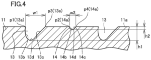
- Fig. 4 is a partially enlarged schematic sectional view illustrating a region IV in Fig. 2 .
- cutting tool 1 is a tool for cutting a fiber reinforced plastic (FRP) material such as carbon fiber reinforced plastic, and mainly includes a shaft portion 30 and at least two main cutting edge portions 11. In the present embodiment, the number of main cutting edge portions 11 is five.
- Shaft portion 30 has substantially a cylindrical shape. Shaft portion 30 extends along a central axis R. Shaft portion 30 has a front end face 2a, a rear end face 2b, and an outer peripheral surface 2. Rear end face 2b is located on the side opposite to the front end face 2a. Outer peripheral surface 2 is a surface connecting front end face 2a and rear end face 2b. That is, outer peripheral surface 2 surrounds central axis R. Shaft portion 30 is rotatable about central axis R.
- FRP fiber reinforced plastic
- Shaft portion 30 further includes a shank portion 20 and a cutting portion 10.
- Cutting portion 10 has front end face 2a.
- Shank portion 20 has rear end face 2b. That is, cutting portion 10 is connected to shank portion 20.
- a blade length W of cutting portion 10 is a distance from front end face 2a to an end portion of main cutting edge portion 11 on the rear end face 2b side in first direction X.
- Front end face 2a and rear end face 2b are perpendicular to central axis R. That is, front end face 2a and rear end face 2b are perpendicular to outer peripheral surface 2.
- a cutting diameter is, for example, 10 mm.
- the cutting diameter may be, for example, greater than or equal to 2 mm or less than or equal to 20 mm, and it may be 3 mm.
- main cutting edge portions 11 are formed on outer peripheral surface 2.
- Main cutting edge portions 11 are helically disposed on outer peripheral surface 2.
- each of main cutting edge portions 11 has a main rake face 11b, a main flank face 11c, and a main cutting edge 11a.
- Main cutting edge 11a is disposed on outer peripheral surface 2.
- Main rake face 11b is formed so as to extend from main cutting edge 11a in a direction toward central axis R from main cutting edge 11a.
- Main flank face 11c is located on a side opposite to main rake face 11b as viewed from main cutting edge 11a.
- Main rake face 11b is connected to main flank face 11c via main cutting edge 11a.
- Main cutting edge 11a has a main helix angle ⁇ 1.
- main helix angle ⁇ 1 is an angle that is a narrower angle out of angles formed by a tangent of main cutting edge 11a and central axis R at a point where central axis R and main cutting edge 1 1a intersect, as illustrated in Fig. 1 .
- a first nick portion 13 includes a first nick rake face 13b, a first nick facing face 13c, a first nick cutting edge 13a, and a first nick connection portion 13e.
- Each of first nick rake face 13b and first nick facing face 13c is connected to main rake face 11b and main flank face 11c.
- First nick rake face 13b is connected to main flank face 11c via first nick cutting edge 13a.
- First nick facing face 13c is connected to main flank face 11c via first nick connection portion 13e.
- Main cutting edge 11a and first nick cutting edge 13a meet at a first intersection point p1.
- First nick connection portion 13e and main cutting edge 11a meet at a third intersection point p3. That is, first intersection point p1 is located on outer peripheral surface 2 as illustrated in Fig. 3 .
- Third intersection point p3 is located on outer peripheral surface 2.
- a region IV illustrated in Fig. 2 is a cross-sectional region of main cutting edge portion 11 obtained by cutting main cutting edge portion 11 in a direction perpendicular to central axis R from a line segment along main cutting edge 1 1a of main cutting edge portion 11. That is, region IV is a cross-sectional region of main cutting edge portion 11 including first intersection point p1, a second intersection point p2, third intersection point p3, and a fourth intersection point p4.
- Fig. 4 is a partially enlarged schematic sectional view of a cross-sectional region of main cutting edge portion 11 in region IV. The schematic sectional view illustrated in Fig. 4 schematically illustrates main cutting edge portion 11 including first nick portion 13 and a second nick portion 14 to be described later.
- FIG. 4 illustrates main cutting edge 11a as a straight line for the sake of description.
- a vertical direction in Fig. 4 indicates a radial direction around central axis R of cutting tool 1.
- first nick rake face 13b and first nick facing face 13c are formed to extend toward central axis R from main cutting edge 11a.
- First nick rake face 13b and first nick facing face 13c are connected to each other with a first nick bottom portion 13d.
- First nick bottom portion 13d is a portion closest to central axis R in first nick portion 13. That is, in first nick portion 13, first nick bottom portion 13d is a point farthest from outer peripheral surface 2 in the direction toward central axis R.
- a distance from outer peripheral surface 2 to first nick bottom portion 13d is a depth h1.
- a width w1 of first nick portion 13 is a length of a line segment connecting first intersection point p1 and third intersection point p3 of first nick portion 13.
- a cross-sectional area A1 of first nick portion 13 is an area of a region surrounded by a straight line connecting first intersection point p1 and third intersection point p3, first nick rake face 13b, and first nick facing face 13c illustrated in Fig. 4 .
- Width w1 of first nick portion 13 may be, for example, greater than or equal to 0.35 mm and less than or equal to 4.2 mm.
- Depth h1 of first nick portion 13 may be, for example, greater than or equal to 0.1 mm and less than or equal to 3.4 mm.
- First nick cutting edge 13a has a reverse helix angle ⁇ 2.
- reverse helix angle ⁇ 2 is an angle that is a narrower angle out of angles formed by a tangent of first nick cutting edge 13a and central axis R at a point where central axis R and first nick cutting edge 13a intersect, as illustrated in Fig. 1 .
- reverse helix angle ⁇ 2 of first nick cutting edge 13a is a helix angle in opposite direction with respect to main helix angle ⁇ 1 of main cutting edge 11a as viewed from central axis R as illustrated in Fig. 1 .
- main cutting edge portion 11 includes first nick portion 13. Due to first nick portion 13 described above being provided, generation of vibration is suppressed and cutting resistance is reduced during cutting of a workpiece.
- cutting tool 1 is characterized in that, as illustrated in Figs. 1 to 4 , main cutting edge portion 11 of cutting tool 1 includes second nick portion 14. Specifically, in each of main cutting edge portions 11, second nick portion 14 is disposed so as to be sandwiched between two first nick portions 13 in first direction X as illustrated in Fig. 1 . Second nick portion 14 may be disposed at, for example, an intermediate position between two first nick portions 13. Second nick portion 14 may be disposed at a position other than the intermediate position of two first nick portions 13, as long as the strength of cutting tool 1 can be ensured. For example, a plurality of (for example, two) second nick portions 14 may be provided between two first nick portions 13.
- second nick portion 14 is different in shape from first nick portion 13.
- the relationship between first nick portion 13 and second nick portion 14 satisfies at least one of a first condition and a second condition.
- the first condition is that width w1 of first nick portion 13 is different from a width w2 of second nick portion 14.
- the second condition is that depth h1 of first nick portion 13 is different from a depth h2 of second nick portion 14.
- second nick portion 14 is disposed within a first region A.
- First region A is a section within ⁇ 30% of blade length W of a region B where main cutting edge portions 11 are formed from a center C of region B in first direction X.
- region B where main cutting edge portions 11 are formed is a region up to a position away from front end face 2a of cutting portion 10 by blade length W in first direction X.
- Center C is a position away from front end face 2a by a half length of blade length W in first direction X.
- first region A is a region within ⁇ 30% of blade length W of cutting portion 10 from center C in first direction X based on center C.
- second nick portion 14 is located on outer peripheral surface 2 of cutting portion 10 in first region A.
- Second nick portion 14 may be formed in a region other than first region A within region B where main cutting edge portions 11 are formed. However, the formation of second nick portion 14 may become more difficult at a position closer to front end face 2a and shank portion 20 due to a manufacturing problem.
- second nick portion 14 includes a second nick rake face 14b, a second nick facing face 14c, a second nick cutting edge 14a, and a second nick connection portion 14e.
- Each of second nick rake face 14b and second nick facing face 14c is connected to main rake face 11b and main flank face 11c.
- Second nick rake face 14b is connected to main flank face 11c via second nick cutting edge 14a.
- Second nick facing face 14c is connected to main flank face 11c via second nick connection portion 14e.
- Main cutting edge 11a and second nick cutting edge 14a meet at second intersection point p2.
- Second nick connection portion 14e and main cutting edge 11a meet at fourth intersection point p4. That is, second intersection point p2 is located on outer peripheral surface 2 as illustrated in Fig. 3 .
- Fourth intersection point p4 is located on outer peripheral surface 2.
- second nick rake face 14b and second nick facing face 14c are formed to extend toward central axis R from main cutting edge 11a.
- Second nick rake face 14b and second nick facing face 14c are connected to each other with a second nick bottom portion 14d.
- Second nick bottom portion 14d is a portion closest to central axis R in second nick portion 14. That is, in second nick portion 14, second nick bottom portion 14d is a point farthest from outer peripheral surface 2 in the direction toward central axis R.
- a distance from outer peripheral surface 2 to second nick bottom portion 14d is a depth h2. As illustrated in Fig.
- width w2 of second nick portion 14 is a length of a line segment connecting second intersection point p2 and fourth intersection point p4 of second nick portion 14.
- a cross-sectional area A2 of second nick portion 14 is an area of a region surrounded by a straight line connecting second intersection point p2 and fourth intersection point p4, second nick rake face 14b, and second nick facing face 14c illustrated in Fig. 4 .
- width w1 of first nick portion 13, depth h1 of first nick portion 13, width w2 of second nick portion 14, and depth h2 of second nick portion 14 are measured from the profile shapes of first nick portion 13 and second nick portion 14.
- the profile shapes of first nick portion 13 and second nick portion 14 may be measured using a non-contact three-dimensional measuring machine manufactured by Bruker Alicona.
- Cross-sectional area A1 of first nick portion 13 and cross-sectional area A2 of second nick portion 14 can be calculated from the profile shapes of first nick portion 13 and second nick portion 14 described above.
- Second nick cutting edge 14a has a reverse helix angle ⁇ 3.
- reverse helix angle ⁇ 3 is an angle that is a narrower angle out of angles formed by a tangent of second nick cutting edge 14a and central axis R at a point where central axis R and second nick cutting edge 14a intersect, as illustrated in Fig. 1 .
- reverse helix angle ⁇ 3 of second nick cutting edge 14a is a helix angle in opposite direction with respect to main helix angle ⁇ 1 of main cutting edge 11a as viewed from central axis R as illustrated in Fig. 1 .
- main cutting edge portion 11 includes second nick portion 14.
- the number of first nick portions 13 is, for example, greater than or equal to one.
- the number of first nick portions 13 may be two or three.
- the number of first nick portions 13 included in each of main cutting edge portions 11 is preferably smaller than the number of main cutting edge portions 11 included in cutting tool 1. From a different point of view, the number of main cutting edge portions 11 is preferably larger than the number of first nick portions 13 included in each of main cutting edge portions 11.
- first nick portions 13 can be easily arranged so as not to overlap each other in the rotation direction of cutting tool 1, and thus, during cutting of the workpiece, it is possible to prevent the occurrence of a region that is not cut on the cut surface of the workpiece when cutting tool 1 makes one rotation.
- the number of second nick portions 14 included in each of main cutting edge portions 11 is, for example, greater than or equal to one.
- the number of second nick portions 14 included in each of main cutting edge portions 11 may be two or three.
- cutting tool 1 may be coated with diamond. With this configuration, the strength and tool life of cutting tool 1 can be improved.
- Cutting tool 1 includes shaft portion 30 and at least two main cutting edge portions 11.
- Shaft portion 30 extends along a central axis R.
- Shaft portion 30 has outer peripheral surface 2.
- Outer peripheral surface 2 surrounds central axis R.
- At least two main cutting edge portions 11 are helically disposed on outer peripheral surface 2.
- Main cutting edge portions 11 have main cutting edge 11a.
- Main cutting edge 11a has helix angle ⁇ 1. In a section within ⁇ 30% of blade length W of region B from center C of region B in a direction along central axis R, main cutting edge portions 11 have at least one first nick portion 13 and at least one second nick portion 14.
- Main cutting edge portions 11 are formed in region B.
- First nick portion 13 and second nick portion 14 have helix angles ⁇ 2 and ⁇ 3 in an opposite direction with respect to helix angle ⁇ 1.
- the relationship between first nick portion 13 and second nick portion 14 satisfies at least one of the first condition and the second condition.
- the first condition is that width w1 of first nick portion 13 is different from width w2 of second nick portion 14.
- the second condition is that depth h1 of first nick portion 13 is different from depth h2 of second nick portion 14.
- the first condition may be that width w1 of first nick portion 13 is greater than or equal to 2 times and less than or equal to 10 times width w2 of second nick portion 14.
- the second condition may be that depth h1 of first nick portion 13 is greater than or equal to two times and less than or equal to 15 times depth h2 of second nick portion 14.
- cross-sectional area A1 of first nick portion 13 is greater than or equal to 5 times and less than or equal to 120 times cross-sectional area A2 of second nick portion 14.
- the number of main cutting edge portions 11 may be larger than the number of first nick portions 13 included in each of main cutting edge portions 11. This configuration can prevent an occurrence of an uncut portion of the workpiece during cutting when cutting tool 1 makes one rotation.
- helix angle ⁇ 1 of main cutting edge 11a may be greater than or equal to 30° and less than or equal to 50°.
- helix angles ⁇ 2 and ⁇ 3 in the opposite direction with respect to helix angle ⁇ 1 may be greater than or equal to 30° and less than or equal to 50°.
- main cutting edge portion 11 may include at least two first nick portions 13.
- Second nick portion 14 may be disposed at an intermediate position between two first nick portions 13. With this configuration, it is possible to minimize a decrease in strength of main cutting edge portion 11 due to the formation of second nick portion 14.
- Cutting tool 1 may be coated with diamond. With this configuration, the strength and tool life of cutting tool 1 can be improved.
- Test 1 was carried out to evaluate the finish of the cut surface of a workpiece, the chip discharge performance, and the tool life of cutting tool 1 due to the presence or absence of second nick portion 14.
- Three kinds of cutting tools 1 from Sample 1 to Sample 3 were used as objects for the test.
- the cutting diameter of cutting tool 1 according to each of Samples 1 to 3 is 10 mm, and the number of main cutting edge portions 11 is five.
- the number of first nick portions 13 in one main cutting edge portion 11 is six.
- the main cutting edge portion 11 has first nick portion 13, but does not have second nick portion 14.
- main cutting edge portion 11 includes first nick portion 13 and second nick portion 14.
- the number of second nick portions 14 in first region A in one main cutting edge portion 11 in Sample 3 is six.
- Width w1 of first nick portion 13 of cutting tool 1 according to Sample 2 is smaller than widths w1 of first nick portions 13 of cutting tools 1 according to Sample 1 and Sample 3.
- First nick portion 13 in each of Sample 1 and Sample 3 has width w1 of 2.0 mm and depth h1 of 1.5 mm.
- First nick portion 13 in Sample 2 has width w1 of 1.0 mm, and depth h1 of 0.6 mm.
- Second nick portion 14 in Sample 3 has width w2 of 0.5 mm and depth h2 of 0.3 mm. In this way, the influence of width w1 of first nick portion 13 and the influence of the presence or absence of second nick portion 14 were examined.
- the workpiece is CFRP.
- the thickness of the CFRP is 6 mm.
- the rotation speed of cutting tool 1 was set to 4000 rpm, and the machining speed was set to 400 mm/min.
- Table 1 shows, from the left, width w1 of first nick portion 13 and whether or not second nick portion 14 is provided as the conditions, and the finish of the cut surface of the workpiece, the chip discharge performance, and the tool life of cutting tool 1 as the test results.
- A, B, and C indicate the evaluation in each of the finish of the cut surface, the chip discharge performance, and the tool life of cutting tool 1 in Table 1.
- B indicates that the result is better than the result indicated as C.
- A indicates that the result is better than the result indicated as B. That is, A indicates that the evaluation result is the best of the results indicated by A, B, and C.
- the result indicating that the chip discharge performance is good indicates that clogging due to chips can be suppressed.
- Test 2 was carried out to evaluate the finish of the cut surface of a workpiece, chip discharge performance, and the tool life of cutting tool 1 due to the shape of second nick portion 14.
- Ten kinds of cutting tools 1 from Sample 4 to Sample 13 were used as objects for the test.
- main cutting edge portion 11 has first nick portion 13, but does not have second nick portion 14.
- main cutting edge portion 11 includes first nick portion 13 and second nick portion 14.
- the influence caused mainly by changing the width ratio (w1/w2), the depth ratio (h1/h2), and the cross-sectional area ratio (A1/A2) was examined.
- the width ratio is a value obtained by dividing width w1 of first nick portion 13 by width w2 of second nick portion 14.
- the depth ratio is a value obtained by dividing depth h1 of first nick portion 13 by depth h2 of second nick portion 14.
- the cross-sectional area ratio is a value obtained by dividing cross-sectional area A1 of first nick portion 13 by cross-sectional area A2 of second nick portion 14.
- the cutting diameter of cutting tool 1 according to each of Samples 4 to 10 and Sample 13 is 10 mm.
- the cutting diameter of cutting tool 1 according to each of Samples 11 and 12 is 3 mm.
- main helix angle ⁇ 1 of main cutting edge 11a is 45°.
- main helix angles ⁇ 1 of main cutting edges 11a are within a range from 20° to 50°, and are different from each other.
- Cutting tool 1 according to each of Samples 4 to 12 is coated with diamond.
- cutting tool 1 according to Samples 13 is not coated with diamond.
- the number of main cutting edge portions 11 is five, and the number of first nick portions 13 and the number of second nick portions 14 in one main cutting edge portion 11 are each six.
- the number of main cutting edge portions 11 is three, and the number of first nick portions 13 and the number of second nick portions 14 in one main cutting edge portion 11 are each four.
- the workpiece is CFRP.
- the thickness of the CFRP is 6 mm.
- the rotation speed of cutting tool 1 was set to 8000 rpm, and the machining speed was set to 1600 mm/min.
- Table 2 shows, from the left, the width ratio, the depth ratio, the cross-sectional area ratio, main helix angle ⁇ 1, and whether or not diamond coating is provided as the conditions, and the finish of the cut surface of the workpiece, the chip discharge performance, and the tool life of cutting tool 1 as the test results.
- A, B, C, and D indicate the evaluation in each of the finish of the cut surface, the chip discharge performance, and the tool life of cutting tool 1 in Table 2.
- C indicates that the result is better than the result indicated as D.
- B indicates that the result is better than the result indicated as C.
- A indicates that the result is better than the result indicated as B. That is, A indicates that the evaluation result is the best of the results indicated by A, B, C, and D.
- the finish of the cut surface by cutting tools 1 according to Samples 5 to 13 is improved as compared with the finish of the cut surface by cutting tool 1 according to Sample 4.
- the chip discharge performance of cutting tools 1 according to Samples 5 to 13 is improved as compared with the chip discharge performance of cutting tool 1 according to Sample 4.
- the finish of the cut surface and the chip discharge performance are improved by additionally providing second nick portion 14 in addition to first nick portion 13 in main cutting edge portion 11.
- Test 2 has the same result as Test 1.
- the width ratio of cutting tool 1 according to each of Samples 7 and 9 is 11. Therefore, the length of main cutting edge 11a becomes insufficient, and thus, the finish of the cut surface deteriorates. In view of this, the width ratio is preferably less than or equal to 10.
- cutting tool 1 according to Sample 8 has a slow helix design in which main helix angle ⁇ 1 of the main cutting edge is 30°, the finish of the cut surface and the chip discharge performance are improved.
- Cutting tool 1 according to Sample 10 has a depth ratio of 17. As a result, the rigidity of cutting tool 1 is low. Therefore, the depth ratio is preferably less than or equal to 16.
- width w1 of first nick portion 13 is preferably greater than or equal to 2 times and less than or equal to 10 times width w2 of second nick portion 14.
- Depth h1 of first nick portion 13 is preferably greater than or equal to 2 times and less than or equal to 15 times depth h2 of second nick portion 14.
- cross-sectional area A1 of first nick portion 13 is preferably greater than or equal to 5 times and less than or equal to 120 times cross-sectional area A2 of second nick portion 14.
- second nick portion 14 in main cutting edge portion 11 may reduce the tool life of cutting tool 1. From the test results of cutting tools 1 according to Sample 6 and Sample 13, it can be seen that the tool life is significantly improved by coating cutting tool 1 with diamond.
- Fig. 5 is a partially enlarged plan view illustrating a first modification of cutting tool 1 according to the first embodiment.
- Fig. 5 corresponds to Fig. 2 .
- Fig. 6 is a partially enlarged schematic sectional view illustrating region VI in Fig. 5.
- Fig. 6 corresponds to Fig. 4 .
- Cutting tool 1 illustrated in Figs. 5 and 6 basically has the same configuration as cutting tool 1 illustrated in Figs. 1 to 4 , but is different from cutting tool 1 illustrated in Figs. 1 to 4 in that two second nick portions 14 are formed between two first nick portions 13. Specifically, two second nick portions 14 are disposed in main cutting edge portion 11 so as to be sandwiched between two first nick portions 13 as illustrated in Fig. 6 .
- the number of second nick portions 14 is not limited to two.
- three second nick portions 14 may be formed in main cutting edge portion 11 so as to be sandwiched between two first nick portions 13.
- Providing a plurality of second nick portions 14 between two first nick portions 13 as described above can significantly suppress vibration generated during cutting. As a result, the finish quality of the machined surface of the workpiece cut by cutting tool 1 is further improved.
- Fig. 7 is a partially enlarged plan view illustrating a second modification of cutting tool 1 according to the first embodiment.
- Fig. 7 corresponds to Fig. 2 .
- Fig. 8 is a partially enlarged schematic sectional view illustrating region VIII in Fig. 7.
- Fig. 8 corresponds to Fig. 4 .
- Cutting tool 1 illustrated in Figs. 7 and 8 basically has the same configuration as cutting tool 1 illustrated in Figs. 1 to 4 , but is different from cutting tool 1 illustrated in Figs. 1 to 4 in that width w2 of second nick portion 14 is larger than width w1 of first nick portion 13. It is only sufficient that depth h1 of first nick portion 13 is larger than depth h2 of second nick portion 14 in order to ensure the chip discharge performance. Alternatively, it is only sufficient that width w1 of first nick portion 13 is larger than width w2 of second nick portion 14. Specifically, the relationship between first nick portion 13 and second nick portion 14 satisfies at least one of a first condition and a second condition from the results of Test 2 described above.
- the first condition is that width w1 of first nick portion 13 is greater than or equal to 2 times and less than or equal to 10 times width w2 of second nick portion 14.
- the second condition is that depth h1 of first nick portion 13 is greater than or equal to 2 times and less than or equal to 15 times depth h2 of second nick portion 14.
- cutting tool 1 can suppress vibration generated during cutting while ensuring chip discharge performance.
- 1 cutting tool 2 outer peripheral surface, 2a front end face, 2b rear end face, 10 cutting portion, 11 main cutting edge portion, 11a main cutting edge, 11b main rake face, 11c main flank face, 13 first nick portion, 13a first nick cutting edge, 13b first nick rake face, 13c first nick facing face, 13d first nick bottom portion, 13e first nick connection portion, 14 second nick portion, 14a second nick cutting edge, 14b second nick rake face, 14c second nick facing face, 14d second nick bottom portion, 14e second nick connection portion, 20 shank portion, 30 shaft portion, A first region, A1, A2 cross-sectional area, B region, C center, R central axis, W blade length, X first direction, h1, h2 depth, w1, w2 width, p1 first intersection point, p2 second intersection point, p3 third intersection point, p4 fourth intersection point
Landscapes
- Engineering & Computer Science (AREA)
- Mechanical Engineering (AREA)
- Milling Processes (AREA)
Abstract
Description
- The present disclosure relates to a cutting tool.
- Conventionally, a cutting tool has been known that includes a rotatable main body, a main cutting edge having a helix angle on an outer periphery of the main body, and nick cutting edges arranged at a reverse helix angle with respect to the helix angle of the main cutting edge (see, for example,
Japanese Patent Laying-Open No. 2011-20248 - PTL 1:
Japanese Patent Laying-Open No. 2011-20248 - A cutting tool according to one aspect of the present disclosure includes a shaft portion and at least two main cutting edge portions. The shaft portion extends along a central axis. The shaft portion has an outer peripheral surface. The outer peripheral surface surrounds the central axis. The at least two main cutting edge portions are helically disposed on the outer peripheral surface. The main cutting edge portions have a main cutting edge. The main cutting edge has a helix angle. In a section within ±30% of a blade length of a region from a center of the region in a direction along the central axis, the main cutting edge portions have at least one first nick portion and at least one second nick portion. The main cutting edge portions are formed in the region. The first nick portion and the second nick portion have helix angles in an opposite direction with respect to the helix angle. The relationship between the first nick portion and the second nick portion satisfies at least one of a first condition and a second condition. The first condition is that a width of the first nick portion is different from a width of the second nick portion. The second condition is that a depth of the first nick portion is different from a depth of the second nick portion.
-
-
Fig. 1 is a plan view of a cutting tool according to a first embodiment. -
Fig. 2 is a partially enlarged plan view of a region II inFig. 1 . -
Fig. 3 is a cross-sectional view taken along line III-III inFig. 2 . -
Fig. 4 is a partially enlarged schematic sectional view illustrating a region IV inFig. 2 . -
Fig. 5 is a partially enlarged plan view illustrating a first modification of the cutting tool according to the first embodiment. -
Fig. 6 is a partially enlarged schematic sectional view illustrating a region VI inFig. 5 . -
Fig. 7 is a partially enlarged plan view illustrating a second modification of the cutting tool according to the first embodiment. -
Fig. 8 is a partially enlarged schematic sectional view illustrating a region VIII inFig. 7 . - In the conventional cutting tool, the number of flutes of the nicked cutting edge is set to be different from the number of main cutting edges, by which a workpiece having a satisfactory cut surface can be obtained with the vibration of the workpiece being suppressed. However, there is a limit to suppression of vibration of the workpiece.
- The present disclosure has been made to solve the above problems. More specifically, the present invention provides a cutting tool capable of suppressing vibration of a workpiece during cutting work.
- According to the cutting tool of the present disclosure, vibration of a workpiece during cutting can be suppressed.
- First, embodiments of the present disclosure will be listed and described.
- (1) A cutting tool according to one aspect of the present disclosure includes a shaft portion and at least two main cutting edge portions. The shaft portion extends along a central axis. The shaft portion has an outer peripheral surface. The outer peripheral surface surrounds the central axis. The at least two main cutting edge portions are helically disposed on the outer peripheral surface. The main cutting edge portions have a main cutting edge. The main cutting edge has a helix angle. In a section within ±30% of a blade length of a region from a center of the region in a direction along the central axis, the main cutting edge portions have at least one first nick portion and at least one second nick portion. The main cutting edge portions are formed in the region. The first nick portion and the second nick portion have helix angles in an opposite direction with respect to the helix angle. The relationship between the first nick portion and the second nick portion satisfies at least one of a first condition and a second condition. The first condition is that a width of the first nick portion is different from a width of the second nick portion. The second condition is that a depth of the first nick portion is different from a depth of the second nick portion.
- (2) In the cutting tool according to (1), the first condition may be that the width of the first nick portion is greater than or equal to 2 times and less than or equal to 10 times the width of the second nick portion. The second condition may be that the depth of the first nick portion is greater than or equal to 2 times and less than or equal to 15 times the depth of the second nick portion.
- (3) In the cutting tool according to (1) or (2), a cross-sectional area of the first nick portion may be greater than or equal to 5 times and less than or equal to 120 times a cross-sectional area of the second nick portion.
- (4) In the cutting tool according to any one of (1) to (3), the number of the main cutting edge portions may be larger than the number of the first nick portions included in each of the main cutting edge portions.
- (5) In the cutting tool according to any one of (1) to (4), the helix angle of the main cutting edge may be greater than or equal to 30° and less than or equal to 50°. The helix angle in the opposite direction with respect to the helix angle in each of the first nick portion and the second nick portion may be greater than or equal to 30° and less than or equal to 50°.
- (6) In the cutting tool according to any one of (1) to (5), the main cutting edge portions may include at least two first nick portions. The second nick portion may be disposed at an intermediate position between two first nick portions.
- (7) The cutting tool according to any one of (1) to (6) may be coated with diamond.
- Embodiments of the present disclosure will now be described in detail with reference to the drawings. In the following drawings, the same or corresponding parts are denoted by the same reference numerals, and redundant description will not be repeated.
-
Fig. 1 is a plan view of acutting tool 1 according to the present embodiment.Fig. 2 is a partially enlarged plan view of a region II inFig. 1 .Fig. 3 is a cross-sectional view taken along line III-III inFig. 2 .Fig. 4 is a partially enlarged schematic sectional view illustrating a region IV inFig. 2 . - As illustrated in
Figs. 1 to 4 , cuttingtool 1 according to an aspect of the present disclosure is a tool for cutting a fiber reinforced plastic (FRP) material such as carbon fiber reinforced plastic, and mainly includes ashaft portion 30 and at least two maincutting edge portions 11. In the present embodiment, the number of maincutting edge portions 11 is five.Shaft portion 30 has substantially a cylindrical shape.Shaft portion 30 extends along a central axisR. Shaft portion 30 has afront end face 2a, arear end face 2b, and an outerperipheral surface 2.Rear end face 2b is located on the side opposite to thefront end face 2a. Outerperipheral surface 2 is a surface connectingfront end face 2a andrear end face 2b. That is, outerperipheral surface 2 surrounds central axisR. Shaft portion 30 is rotatable about central axis R. -
Shaft portion 30 further includes ashank portion 20 and a cuttingportion 10. Cuttingportion 10 hasfront end face 2a.Shank portion 20 hasrear end face 2b. That is, cuttingportion 10 is connected toshank portion 20. InFig. 1 , when a direction in which central axis R extends is defined as a first direction X, a blade length W of cuttingportion 10 is a distance fromfront end face 2a to an end portion of maincutting edge portion 11 on therear end face 2b side in first direction X.Front end face 2a andrear end face 2b are perpendicular to central axis R. That is,front end face 2a andrear end face 2b are perpendicular to outerperipheral surface 2. A cutting diameter is, for example, 10 mm. The cutting diameter may be, for example, greater than or equal to 2 mm or less than or equal to 20 mm, and it may be 3 mm. - In cutting
portion 10, five maincutting edge portions 11 are formed on outerperipheral surface 2. Maincutting edge portions 11 are helically disposed on outerperipheral surface 2. As illustrated inFig. 3 , each of maincutting edge portions 11 has amain rake face 11b, amain flank face 11c, and amain cutting edge 11a.Main cutting edge 11a is disposed on outerperipheral surface 2.Main rake face 11b is formed so as to extend frommain cutting edge 11a in a direction toward central axis R frommain cutting edge 11a.Main flank face 11c is located on a side opposite tomain rake face 11b as viewed frommain cutting edge 11a.Main rake face 11b is connected tomain flank face 11c viamain cutting edge 11a. -
Main cutting edge 11a has a main helix angle θ1. In plan view viewed from a direction perpendicular to central axis R, main helix angle θ1 is an angle that is a narrower angle out of angles formed by a tangent ofmain cutting edge 11a and central axis R at a point where central axis R andmain cutting edge 1 1a intersect, as illustrated inFig. 1 . - As illustrated in
Figs. 2 and4 , afirst nick portion 13 includes a firstnick rake face 13b, a firstnick facing face 13c, a firstnick cutting edge 13a, and a firstnick connection portion 13e. Each of firstnick rake face 13b and firstnick facing face 13c is connected tomain rake face 11b andmain flank face 11c. Firstnick rake face 13b is connected tomain flank face 11c via firstnick cutting edge 13a. Firstnick facing face 13c is connected tomain flank face 11c via firstnick connection portion 13e.Main cutting edge 11a and firstnick cutting edge 13a meet at a first intersection point p1. Firstnick connection portion 13e andmain cutting edge 11a meet at a third intersection point p3. That is, first intersection point p1 is located on outerperipheral surface 2 as illustrated inFig. 3 . Third intersection point p3 is located on outerperipheral surface 2. - A region IV illustrated in
Fig. 2 is a cross-sectional region of maincutting edge portion 11 obtained by cutting maincutting edge portion 11 in a direction perpendicular to central axis R from a line segment alongmain cutting edge 1 1a of maincutting edge portion 11. That is, region IV is a cross-sectional region of maincutting edge portion 11 including first intersection point p1, a second intersection point p2, third intersection point p3, and a fourth intersection point p4.Fig. 4 is a partially enlarged schematic sectional view of a cross-sectional region of maincutting edge portion 11 in region IV. The schematic sectional view illustrated inFig. 4 schematically illustrates maincutting edge portion 11 includingfirst nick portion 13 and asecond nick portion 14 to be described later. Although actualmain cutting edge 11a has a curved shape because it is helically arranged,Fig. 4 illustratesmain cutting edge 11a as a straight line for the sake of description. A vertical direction inFig. 4 indicates a radial direction around central axis R of cuttingtool 1. - As illustrated in
Fig. 4 , firstnick rake face 13b and firstnick facing face 13c are formed to extend toward central axis R frommain cutting edge 11a. Firstnick rake face 13b and firstnick facing face 13c are connected to each other with a firstnick bottom portion 13d. Firstnick bottom portion 13d is a portion closest to central axis R infirst nick portion 13. That is, infirst nick portion 13, firstnick bottom portion 13d is a point farthest from outerperipheral surface 2 in the direction toward central axis R. A distance from outerperipheral surface 2 to firstnick bottom portion 13d is a depth h1. As illustrated inFig. 4 , a width w1 offirst nick portion 13 is a length of a line segment connecting first intersection point p1 and third intersection point p3 offirst nick portion 13. Note that a cross-sectional area A1 offirst nick portion 13 is an area of a region surrounded by a straight line connecting first intersection point p1 and third intersection point p3, firstnick rake face 13b, and firstnick facing face 13c illustrated inFig. 4 . Width w1 offirst nick portion 13 may be, for example, greater than or equal to 0.35 mm and less than or equal to 4.2 mm. Depth h1 offirst nick portion 13 may be, for example, greater than or equal to 0.1 mm and less than or equal to 3.4 mm. - First
nick cutting edge 13a has a reverse helix angle θ2. In plan view viewed from the direction perpendicular to central axis R, reverse helix angle θ2 is an angle that is a narrower angle out of angles formed by a tangent of firstnick cutting edge 13a and central axis R at a point where central axis R and firstnick cutting edge 13a intersect, as illustrated inFig. 1 . In plan view, reverse helix angle θ2 of firstnick cutting edge 13a is a helix angle in opposite direction with respect to main helix angle θ1 ofmain cutting edge 11a as viewed from central axis R as illustrated inFig. 1 . As described above, maincutting edge portion 11 includesfirst nick portion 13. Due tofirst nick portion 13 described above being provided, generation of vibration is suppressed and cutting resistance is reduced during cutting of a workpiece. - Here, cutting
tool 1 according to the first embodiment is characterized in that, as illustrated inFigs. 1 to 4 , maincutting edge portion 11 of cuttingtool 1 includessecond nick portion 14. Specifically, in each of maincutting edge portions 11,second nick portion 14 is disposed so as to be sandwiched between twofirst nick portions 13 in first direction X as illustrated inFig. 1 .Second nick portion 14 may be disposed at, for example, an intermediate position between twofirst nick portions 13.Second nick portion 14 may be disposed at a position other than the intermediate position of twofirst nick portions 13, as long as the strength of cuttingtool 1 can be ensured. For example, a plurality of (for example, two)second nick portions 14 may be provided between twofirst nick portions 13. - As illustrated in
Fig. 4 ,second nick portion 14 is different in shape fromfirst nick portion 13. Specifically, the relationship betweenfirst nick portion 13 andsecond nick portion 14 satisfies at least one of a first condition and a second condition. The first condition is that width w1 offirst nick portion 13 is different from a width w2 ofsecond nick portion 14. The second condition is that depth h1 offirst nick portion 13 is different from a depth h2 ofsecond nick portion 14. Providingsecond nick portion 14 having a shape different from that offirst nick portion 13 in maincutting edge portion 11 as described above can significantly suppress vibration generated during cutting. As a result, the finish quality of the machined surface of the workpiece cut by cuttingtool 1 is improved. - As illustrated in
Fig. 1 ,second nick portion 14 is disposed within a first region A. First region A is a section within ±30% of blade length W of a region B where maincutting edge portions 11 are formed from a center C of region B in first direction X. Specifically, region B where maincutting edge portions 11 are formed is a region up to a position away fromfront end face 2a of cuttingportion 10 by blade length W in first direction X. Center C is a position away fromfront end face 2a by a half length of blade length W in first direction X. That is, when the direction in whichfront end face 2a is located in first direction X based on center C in first direction X is positive, a surface away from center C by +50% of blade length W of cuttingportion 10 in first direction X from center C isfront end face 2a. From a different point of view, first region A is a region within ±30% of blade length W of cuttingportion 10 from center C in first direction X based on center C. That is,second nick portion 14 is located on outerperipheral surface 2 of cuttingportion 10 in first region A.Second nick portion 14 may be formed in a region other than first region A within region B where maincutting edge portions 11 are formed. However, the formation ofsecond nick portion 14 may become more difficult at a position closer tofront end face 2a andshank portion 20 due to a manufacturing problem. - As illustrated in
Figs. 2 and4 ,second nick portion 14 includes a secondnick rake face 14b, a secondnick facing face 14c, a secondnick cutting edge 14a, and a secondnick connection portion 14e. Each of secondnick rake face 14b and secondnick facing face 14c is connected tomain rake face 11b andmain flank face 11c. Secondnick rake face 14b is connected tomain flank face 11c via secondnick cutting edge 14a. Secondnick facing face 14c is connected tomain flank face 11c via secondnick connection portion 14e.Main cutting edge 11a and secondnick cutting edge 14a meet at second intersection point p2. Secondnick connection portion 14e andmain cutting edge 11a meet at fourth intersection point p4. That is, second intersection point p2 is located on outerperipheral surface 2 as illustrated inFig. 3 . Fourth intersection point p4 is located on outerperipheral surface 2. - As illustrated in
Fig. 4 , secondnick rake face 14b and secondnick facing face 14c are formed to extend toward central axis R frommain cutting edge 11a. Secondnick rake face 14b and secondnick facing face 14c are connected to each other with a secondnick bottom portion 14d. Secondnick bottom portion 14d is a portion closest to central axis R insecond nick portion 14. That is, insecond nick portion 14, secondnick bottom portion 14d is a point farthest from outerperipheral surface 2 in the direction toward central axis R. A distance from outerperipheral surface 2 to secondnick bottom portion 14d is a depth h2. As illustrated inFig. 4 , width w2 ofsecond nick portion 14 is a length of a line segment connecting second intersection point p2 and fourth intersection point p4 ofsecond nick portion 14. Note that a cross-sectional area A2 ofsecond nick portion 14 is an area of a region surrounded by a straight line connecting second intersection point p2 and fourth intersection point p4, secondnick rake face 14b, and secondnick facing face 14c illustrated inFig. 4 . - Note that width w1 of
first nick portion 13, depth h1 offirst nick portion 13, width w2 ofsecond nick portion 14, and depth h2 ofsecond nick portion 14 are measured from the profile shapes offirst nick portion 13 andsecond nick portion 14. The profile shapes offirst nick portion 13 andsecond nick portion 14 may be measured using a non-contact three-dimensional measuring machine manufactured by Bruker Alicona. Cross-sectional area A1 offirst nick portion 13 and cross-sectional area A2 ofsecond nick portion 14 can be calculated from the profile shapes offirst nick portion 13 andsecond nick portion 14 described above. - Second
nick cutting edge 14a has a reverse helix angle θ3. In plan view viewed from the direction perpendicular to central axis R, reverse helix angle θ3 is an angle that is a narrower angle out of angles formed by a tangent of secondnick cutting edge 14a and central axis R at a point where central axis R and secondnick cutting edge 14a intersect, as illustrated inFig. 1 . In plan view, reverse helix angle θ3 of secondnick cutting edge 14a is a helix angle in opposite direction with respect to main helix angle θ1 ofmain cutting edge 11a as viewed from central axis R as illustrated inFig. 1 . As described above, maincutting edge portion 11 includessecond nick portion 14. - It is only sufficient that, in each of main
cutting edge portions 11, the number offirst nick portions 13 is, for example, greater than or equal to one. The number offirst nick portions 13 may be two or three. In addition, the number offirst nick portions 13 included in each of maincutting edge portions 11 is preferably smaller than the number of maincutting edge portions 11 included in cuttingtool 1. From a different point of view, the number of maincutting edge portions 11 is preferably larger than the number offirst nick portions 13 included in each of maincutting edge portions 11. When the number of maincutting edge portions 11 is different from the number offirst nick portions 13 as described above,first nick portions 13 can be easily arranged so as not to overlap each other in the rotation direction of cuttingtool 1, and thus, during cutting of the workpiece, it is possible to prevent the occurrence of a region that is not cut on the cut surface of the workpiece when cuttingtool 1 makes one rotation. - It is only sufficient that the number of
second nick portions 14 included in each of maincutting edge portions 11 is, for example, greater than or equal to one. The number ofsecond nick portions 14 included in each of maincutting edge portions 11 may be two or three. When the number offirst nick portions 13 and the number ofsecond nick portions 14 included in each of maincutting edge portions 11 are large, generation of vibration is further suppressed and cutting resistance is further reduced during cutting of the workpiece by cuttingtool 1. - However, due to
second nick portion 14 being provided, the strength of maincutting edge portion 11 and the tool life may be reduced. In view of this, cuttingtool 1 may be coated with diamond. With this configuration, the strength and tool life of cuttingtool 1 can be improved. - Cutting
tool 1 according to the present disclosure includesshaft portion 30 and at least two maincutting edge portions 11.Shaft portion 30 extends along a central axisR. Shaft portion 30 has outerperipheral surface 2. Outerperipheral surface 2 surrounds central axis R. At least two maincutting edge portions 11 are helically disposed on outerperipheral surface 2. Maincutting edge portions 11 havemain cutting edge 11a.Main cutting edge 11a has helix angle θ1. In a section within ±30% of blade length W of region B from center C of region B in a direction along central axis R, maincutting edge portions 11 have at least onefirst nick portion 13 and at least onesecond nick portion 14. Maincutting edge portions 11 are formed in region B.First nick portion 13 andsecond nick portion 14 have helix angles θ2 and θ3 in an opposite direction with respect to helix angle θ1. The relationship betweenfirst nick portion 13 andsecond nick portion 14 satisfies at least one of the first condition and the second condition. The first condition is that width w1 offirst nick portion 13 is different from width w2 ofsecond nick portion 14. The second condition is that depth h1 offirst nick portion 13 is different from depth h2 ofsecond nick portion 14. - With this configuration, vibration generated during cutting can be greatly suppressed. As a result, the finish quality of the machined surface of the workpiece cut by cutting
tool 1 is improved. - In cutting
tool 1, the first condition may be that width w1 offirst nick portion 13 is greater than or equal to 2 times and less than or equal to 10 times width w2 ofsecond nick portion 14. The second condition may be that depth h1 offirst nick portion 13 is greater than or equal to two times and less than or equal to 15 times depth h2 ofsecond nick portion 14. - With this configuration, vibration generated during cutting can be greatly suppressed, and sufficient discharge performance of chips generated during cutting can be ensured. As a result,
second nick portion 14 is not clogged by chips during cutting, whereby the finish quality of the machined surface of the workpiece is greatly improved. - In cutting
tool 1, cross-sectional area A1 offirst nick portion 13 is greater than or equal to 5 times and less than or equal to 120 times cross-sectional area A2 ofsecond nick portion 14. With this configuration, vibration generated during cutting can be greatly suppressed, and sufficient discharge performance of chips generated during cutting can be ensured. As a result,second nick portion 14 is not clogged by chips during cutting, whereby the finish quality of the machined surface of the workpiece is greatly improved. - In cutting
tool 1, the number of maincutting edge portions 11 may be larger than the number offirst nick portions 13 included in each of maincutting edge portions 11. This configuration can prevent an occurrence of an uncut portion of the workpiece during cutting when cuttingtool 1 makes one rotation. - In cutting
tool 1, helix angle θ1 ofmain cutting edge 11a may be greater than or equal to 30° and less than or equal to 50°. In each offirst nick portion 13 andsecond nick portion 14, helix angles θ2 and θ3 in the opposite direction with respect to helix angle θ1 may be greater than or equal to 30° and less than or equal to 50°. With this configuration, the generation of vibration is suppressed and the cutting resistance is reduced during cutting, and the finish quality of the machined surface is improved, as described later. - In cutting
tool 1, maincutting edge portion 11 may include at least twofirst nick portions 13.Second nick portion 14 may be disposed at an intermediate position between twofirst nick portions 13. With this configuration, it is possible to minimize a decrease in strength of maincutting edge portion 11 due to the formation ofsecond nick portion 14. - Cutting
tool 1 may be coated with diamond. With this configuration, the strength and tool life of cuttingtool 1 can be improved. - In order to verify the effects of cutting
tool 1 according to the first embodiment as described above, the following test was performed. -
Test 1 was carried out to evaluate the finish of the cut surface of a workpiece, the chip discharge performance, and the tool life of cuttingtool 1 due to the presence or absence ofsecond nick portion 14. Three kinds ofcutting tools 1 fromSample 1 to Sample 3 were used as objects for the test. The cutting diameter of cuttingtool 1 according to each ofSamples 1 to 3 is 10 mm, and the number of maincutting edge portions 11 is five. The number offirst nick portions 13 in one maincutting edge portion 11 is six. In each ofSamples cutting edge portion 11 hasfirst nick portion 13, but does not havesecond nick portion 14. On the other hand, in Sample 3, maincutting edge portion 11 includesfirst nick portion 13 andsecond nick portion 14. The number ofsecond nick portions 14 in first region A in one maincutting edge portion 11 in Sample 3 is six. Width w1 offirst nick portion 13 of cuttingtool 1 according toSample 2 is smaller than widths w1 offirst nick portions 13 ofcutting tools 1 according toSample 1 and Sample 3.First nick portion 13 in each ofSample 1 and Sample 3 has width w1 of 2.0 mm and depth h1 of 1.5 mm.First nick portion 13 inSample 2 has width w1 of 1.0 mm, and depth h1 of 0.6 mm.Second nick portion 14 in Sample 3 has width w2 of 0.5 mm and depth h2 of 0.3 mm. In this way, the influence of width w1 offirst nick portion 13 and the influence of the presence or absence ofsecond nick portion 14 were examined. - The workpiece is CFRP. The thickness of the CFRP is 6 mm. As cutting conditions, the rotation speed of cutting
tool 1 was set to 4000 rpm, and the machining speed was set to 400 mm/min. -
[Table 1] Condition Result Width of first nick portion Whether or not second nick portion is provided Finish of cut surface Chip discharge performance Tool life Sample 1 Large Not provided C B A Sample 2 Small Not provided B C C Sample 3 Large Provided A A A - The results of the test are shown in Table 1. Table 1 shows, from the left, width w1 of
first nick portion 13 and whether or notsecond nick portion 14 is provided as the conditions, and the finish of the cut surface of the workpiece, the chip discharge performance, and the tool life of cuttingtool 1 as the test results. Note that A, B, and C indicate the evaluation in each of the finish of the cut surface, the chip discharge performance, and the tool life of cuttingtool 1 in Table 1. B indicates that the result is better than the result indicated as C. A indicates that the result is better than the result indicated as B. That is, A indicates that the evaluation result is the best of the results indicated by A, B, and C. In particular, the result indicating that the chip discharge performance is good indicates that clogging due to chips can be suppressed. - As can be seen from the test results of
cutting tools 1 according toSample 1 andSample 2 in Table 1, when width w1 of the first nick portion is reduced, cross-sectional area A1 offirst nick portion 13 decreases, by which the chip discharge performance deteriorates. Whenfirst nick portion 13 is clogged by the chips, the cutting resistance of cuttingtool 1 increases, and as a result, the tool life of cuttingtool 1 is reduced. - From the test results of cutting
tool 1 according toSamples 1 and 3, the finish of the cut surface is improved by additionally providingsecond nick portion 14 in addition tofirst nick portion 13 in maincutting edge portion 11. This is considered to be because the vibration generated during cutting is reduced, resulting in improvement of finish of the cut surface. Since the area for discharging chips is increased by providingsecond nick portion 14, the chip discharge performance is improved. It is considered that, as a result, the tool life remains satisfactory without being reduced by providingsecond nick portion 14. -
Test 2 was carried out to evaluate the finish of the cut surface of a workpiece, chip discharge performance, and the tool life of cuttingtool 1 due to the shape ofsecond nick portion 14. Ten kinds ofcutting tools 1 from Sample 4 to Sample 13 were used as objects for the test. In cuttingtool 1 according to Sample 4, maincutting edge portion 11 hasfirst nick portion 13, but does not havesecond nick portion 14. On the other hand, in cuttingtool 1 according to each of Samples 5 to 13, maincutting edge portion 11 includesfirst nick portion 13 andsecond nick portion 14. In particular, in cuttingtools 1 according to Samples 5 to 13, the influence caused mainly by changing the width ratio (w1/w2), the depth ratio (h1/h2), and the cross-sectional area ratio (A1/A2) was examined. The width ratio is a value obtained by dividing width w1 offirst nick portion 13 by width w2 ofsecond nick portion 14. The depth ratio is a value obtained by dividing depth h1 offirst nick portion 13 by depth h2 ofsecond nick portion 14. The cross-sectional area ratio is a value obtained by dividing cross-sectional area A1 offirst nick portion 13 by cross-sectional area A2 ofsecond nick portion 14. - The cutting diameter of cutting
tool 1 according to each of Samples 4 to 10 andSample 13 is 10 mm. The cutting diameter of cuttingtool 1 according to each ofSamples 11 and 12 is 3 mm. In cuttingtool 1 according to each of Samples 4 to 6, main helix angle θ1 ofmain cutting edge 11a is 45°. On the other hand, in cuttingtools 1 according to Samples 7 to 10, main helix angles θ1 ofmain cutting edges 11a are within a range from 20° to 50°, and are different from each other. Cuttingtool 1 according to each of Samples 4 to 12 is coated with diamond. On the other hand, cuttingtool 1 according toSamples 13 is not coated with diamond. In addition, in cuttingtools 1 according to Samples 4 to 10 andcutting tool 1 according toSample 13 having a cutting diameter of 10 mm, the number of maincutting edge portions 11 is five, and the number offirst nick portions 13 and the number ofsecond nick portions 14 in one maincutting edge portion 11 are each six. On the other hand, in cuttingtools 1 according toSamples 11 and 12 having a cutting diameter of 3 mm, the number of maincutting edge portions 11 is three, and the number offirst nick portions 13 and the number ofsecond nick portions 14 in one maincutting edge portion 11 are each four. - The workpiece is CFRP. The thickness of the CFRP is 6 mm. As cutting conditions, the rotation speed of cutting
tool 1 was set to 8000 rpm, and the machining speed was set to 1600 mm/min. -
[Table 2] Condition Result Width ratio w1/w2 Depth ratio h1/h2 Cross-sectional area ratio A1/A2 Main helix angle θ1 Diamond coating Finish of cut surface Chip discharge performance Tool life Sample 4 - 45° Provided D D B Sample 5 2 1 1.5 45° Provided B C B Sample 6 4 5 18 45° Provided A A A Sample 7 11 16 125 25° Provided B A C Sample 8 10 5 49 30° Provided A A A Sample 9 11 7 42 40° Provided B A B Sample 10 5 17 74 50° Provided A A B Sample 11 2 2 12 45° Provided A A A Sample 12 1.5 4 19 55° Provided B A B Sample 13 4 5 18 45° Not provided A A C - The results are shown in Table 2. Table 2 shows, from the left, the width ratio, the depth ratio, the cross-sectional area ratio, main helix angle θ1, and whether or not diamond coating is provided as the conditions, and the finish of the cut surface of the workpiece, the chip discharge performance, and the tool life of cutting
tool 1 as the test results. Note that A, B, C, and D indicate the evaluation in each of the finish of the cut surface, the chip discharge performance, and the tool life of cuttingtool 1 in Table 2. C indicates that the result is better than the result indicated as D. B indicates that the result is better than the result indicated as C. A indicates that the result is better than the result indicated as B. That is, A indicates that the evaluation result is the best of the results indicated by A, B, C, and D. - As can be seen from Table 2, the finish of the cut surface by cutting
tools 1 according to Samples 5 to 13 is improved as compared with the finish of the cut surface by cuttingtool 1 according to Sample 4. The chip discharge performance ofcutting tools 1 according to Samples 5 to 13 is improved as compared with the chip discharge performance of cuttingtool 1 according to Sample 4. From the above, the finish of the cut surface and the chip discharge performance are improved by additionally providingsecond nick portion 14 in addition tofirst nick portion 13 in maincutting edge portion 11. In this respect, it can be said thatTest 2 has the same result asTest 1. In particular, it has been found from the test results ofcutting tools 1 according to Samples 5 and 6 that, when the width ratio and the depth ratio increase, the cross-sectional area ratio increases, by which not only the finish of the cut surface but also the chip discharge performance are significantly improved. - The width ratio of cutting
tool 1 according to each of Samples 7 and 9 is 11. Therefore, the length ofmain cutting edge 11a becomes insufficient, and thus, the finish of the cut surface deteriorates. In view of this, the width ratio is preferably less than or equal to 10. Although cuttingtool 1 according to Sample 8 has a slow helix design in which main helix angle θ1 of the main cutting edge is 30°, the finish of the cut surface and the chip discharge performance are improved. - Cutting
tool 1 according toSample 10 has a depth ratio of 17. As a result, the rigidity of cuttingtool 1 is low. Therefore, the depth ratio is preferably less than or equal to 16. From the above results, width w1 offirst nick portion 13 is preferably greater than or equal to 2 times and less than or equal to 10 times width w2 ofsecond nick portion 14. Depth h1 offirst nick portion 13 is preferably greater than or equal to 2 times and less than or equal to 15 times depth h2 ofsecond nick portion 14. From another viewpoint, cross-sectional area A1 offirst nick portion 13 is preferably greater than or equal to 5 times and less than or equal to 120 times cross-sectional area A2 ofsecond nick portion 14. - From the test results of
cutting tools 1 according toSample 11 and Sample 12, each of which has a cutting diameter of 3 mm, providingsecond nick portion 14 in maincutting edge portion 11 improves the finish of the cut surface and the chip discharge performance as in cuttingtool 1 having a cutting diameter of 10 mm. - However, providing
second nick portion 14 in maincutting edge portion 11 may reduce the tool life of cuttingtool 1. From the test results ofcutting tools 1 according to Sample 6 andSample 13, it can be seen that the tool life is significantly improved by coating cuttingtool 1 with diamond. -
Fig. 5 is a partially enlarged plan view illustrating a first modification of cuttingtool 1 according to the first embodiment.Fig. 5 corresponds toFig. 2 .Fig. 6 is a partially enlarged schematic sectional view illustrating region VI inFig. 5. Fig. 6 corresponds toFig. 4 . - Cutting
tool 1 illustrated inFigs. 5 and 6 basically has the same configuration as cuttingtool 1 illustrated inFigs. 1 to 4 , but is different from cuttingtool 1 illustrated inFigs. 1 to 4 in that twosecond nick portions 14 are formed between twofirst nick portions 13. Specifically, twosecond nick portions 14 are disposed in maincutting edge portion 11 so as to be sandwiched between twofirst nick portions 13 as illustrated inFig. 6 . The number ofsecond nick portions 14 is not limited to two. For example, threesecond nick portions 14 may be formed in maincutting edge portion 11 so as to be sandwiched between twofirst nick portions 13. Providing a plurality ofsecond nick portions 14 between twofirst nick portions 13 as described above can significantly suppress vibration generated during cutting. As a result, the finish quality of the machined surface of the workpiece cut by cuttingtool 1 is further improved. -
Fig. 7 is a partially enlarged plan view illustrating a second modification of cuttingtool 1 according to the first embodiment.Fig. 7 corresponds toFig. 2 .Fig. 8 is a partially enlarged schematic sectional view illustrating region VIII inFig. 7. Fig. 8 corresponds toFig. 4 . - Cutting
tool 1 illustrated inFigs. 7 and 8 basically has the same configuration as cuttingtool 1 illustrated inFigs. 1 to 4 , but is different from cuttingtool 1 illustrated inFigs. 1 to 4 in that width w2 ofsecond nick portion 14 is larger than width w1 offirst nick portion 13. It is only sufficient that depth h1 offirst nick portion 13 is larger than depth h2 ofsecond nick portion 14 in order to ensure the chip discharge performance. Alternatively, it is only sufficient that width w1 offirst nick portion 13 is larger than width w2 ofsecond nick portion 14. Specifically, the relationship betweenfirst nick portion 13 andsecond nick portion 14 satisfies at least one of a first condition and a second condition from the results ofTest 2 described above. The first condition is that width w1 offirst nick portion 13 is greater than or equal to 2 times and less than or equal to 10 times width w2 ofsecond nick portion 14. The second condition is that depth h1 offirst nick portion 13 is greater than or equal to 2 times and less than or equal to 15 times depth h2 ofsecond nick portion 14. - With this configuration, cutting
tool 1 can suppress vibration generated during cutting while ensuring chip discharge performance. - It should be understood that the embodiment disclosed herein is illustrative in all respects and not restrictive. The basic scope of the present invention is defined not by the embodiment but by the claims, and is intended to include meanings equivalent to the claims and all modifications within the scope.
- 1 cutting tool, 2 outer peripheral surface, 2a front end face, 2b rear end face, 10 cutting portion, 11 main cutting edge portion, 11a main cutting edge, 11b main rake face, 11c main flank face, 13 first nick portion, 13a first nick cutting edge, 13b first nick rake face, 13c first nick facing face, 13d first nick bottom portion, 13e first nick connection portion, 14 second nick portion, 14a second nick cutting edge, 14b second nick rake face, 14c second nick facing face, 14d second nick bottom portion, 14e second nick connection portion, 20 shank portion, 30 shaft portion, A first region, A1, A2 cross-sectional area, B region, C center, R central axis, W blade length, X first direction, h1, h2 depth, w1, w2 width, p1 first intersection point, p2 second intersection point, p3 third intersection point, p4 fourth intersection point
Claims (6)
- A cutting tool comprising:a shaft portion that extends along a central axis and has an outer peripheral surface surrounding the central axis; andat least two main cutting edge portions helically disposed on the outer peripheral surface, whereinthe main cutting edge portions have a main cutting edge having a helix angle, and include at least one first nick portion and at least one second nick portion that have helix angles in an opposite direction with respect to the helix angle in a section within ±30% of a blade length of a region where the main cutting edge portions are formed from a center of the region in a direction along the central axis, anda relationship between the first nick portion and the second nick portion satisfies at least one of a first condition and a second condition,the first condition being that a width of the first nick portion is different from a width of the second nick portion,the second condition being that a depth of the first nick portion is different from a depth of the second nick portion.
- The cutting tool according to claim 1, whereinthe first condition is that the width of the first nick portion is greater than or equal to 2 times and less than or equal to 10 times the width of the second nick portion, andthe second condition is that the depth of the first nick portion is greater than or equal to 2 times and less than or equal to 15 times the depth of the second nick portion.
- The cutting tool according to claim 1 or 2, wherein a cross-sectional area of the first nick portion is greater than or equal to 5 times and less than or equal to 120 times a cross-sectional area of the second nick portion.
- The cutting tool according to any one of claims 1 to 3, wherein a number of the main cutting edge portions is larger than a number of the first nick portions included in each of the main cutting edge portions.
- The cutting tool according to any one of claims 1 to 4, whereinthe helix angle of the main cutting edge is greater than or equal to 30° and less than or equal to 50°, andthe helix angle in the opposite direction with respect to the helix angle in each of the first nick portion and the second nick portion is greater than or equal to 30° and less than or equal to 50°.
- The cutting tool according to any one of claims 1 to 5, whereinthe main cutting edge portions include at least two first nick portions, each of which is the at least one first nick portion, andthe second nick portion is disposed at an intermediate position between two of the first nick portions.
Applications Claiming Priority (1)
| Application Number | Priority Date | Filing Date | Title |
|---|---|---|---|
| PCT/JP2023/003266 WO2024161564A1 (en) | 2023-02-01 | 2023-02-01 | Cutting tool |
Publications (2)
| Publication Number | Publication Date |
|---|---|
| EP4431211A1 true EP4431211A1 (en) | 2024-09-18 |
| EP4431211A4 EP4431211A4 (en) | 2024-09-18 |
Family
ID=
Also Published As
| Publication number | Publication date |
|---|---|
| JP7298817B1 (en) | 2023-06-27 |
| CN118785987A (en) | 2024-10-15 |
| JPWO2024161564A1 (en) | 2024-08-08 |
| US20240253136A1 (en) | 2024-08-01 |
| CN118785987B (en) | 2025-10-31 |
| WO2024161564A1 (en) | 2024-08-08 |
| US12350745B2 (en) | 2025-07-08 |
Similar Documents
| Publication | Publication Date | Title |
|---|---|---|
| EP3351328B1 (en) | Cutting insert and indexable cutting tool | |
| EP2913132B1 (en) | Ball end mill | |
| US8807882B2 (en) | Face milling cutter | |
| US8556547B2 (en) | Radius end mill | |
| US20130017025A1 (en) | End mill | |
| US10220451B2 (en) | End mill and method for manufacturing machined product | |
| EP4549065A1 (en) | Drill and cutting method | |
| JP5198579B2 (en) | Throw-away cutting rotary tool | |
| JP2016190299A (en) | Total end mill | |
| EP4286083A1 (en) | Drill | |
| JP2010158762A (en) | Method for cutting groove for turbine blade connection, and christmas cutter used for the same | |
| US12186814B2 (en) | Milling tool for milling workpieces | |
| CN112584953B (en) | Ball end mills and cutting inserts | |
| US12350745B2 (en) | Cutting tool | |
| EP4245447B1 (en) | Ball end mill | |
| WO2022049659A1 (en) | Cutting insert for rotational cutting tool and rotational cutting tool | |
| EP4316710A1 (en) | Drill head, tip-interchangeable drill, and drill | |
| JP7594822B2 (en) | End Mills | |
| EP3925721A1 (en) | Endmill | |
| JP4561054B2 (en) | Ball end mill | |
| EP3736070A1 (en) | Radius end mill, machine tool using same, and designing method and machining method for radius end mill | |
| JP2018043321A (en) | Cutting insert and cutting edge exchangeable cutting tool | |
| WO2019220778A1 (en) | Cutting insert for drill, and drill | |
| JP2010030044A (en) | Ball end mill | |
| US20250387839A1 (en) | Cutting tool |
Legal Events
| Date | Code | Title | Description |
|---|---|---|---|
| STAA | Information on the status of an ep patent application or granted ep patent |
Free format text: STATUS: UNKNOWN |
|
| STAA | Information on the status of an ep patent application or granted ep patent |
Free format text: STATUS: THE INTERNATIONAL PUBLICATION HAS BEEN MADE |
|
| PUAI | Public reference made under article 153(3) epc to a published international application that has entered the european phase |
Free format text: ORIGINAL CODE: 0009012 |
|
| STAA | Information on the status of an ep patent application or granted ep patent |
Free format text: STATUS: REQUEST FOR EXAMINATION WAS MADE |
|
| 17P | Request for examination filed |
Effective date: 20231023 |
|
| A4 | Supplementary search report drawn up and despatched |
Effective date: 20240711 |
|
| AK | Designated contracting states |
Kind code of ref document: A1 Designated state(s): AL AT BE BG CH CY CZ DE DK EE ES FI FR GB GR HR HU IE IS IT LI LT LU LV MC ME MK MT NL NO PL PT RO RS SE SI SK SM TR |
|
| STAA | Information on the status of an ep patent application or granted ep patent |
Free format text: STATUS: EXAMINATION IS IN PROGRESS |
|
| 17Q | First examination report despatched |
Effective date: 20250522 |
|
| DAV | Request for validation of the european patent (deleted) | ||
| DAX | Request for extension of the european patent (deleted) |