EP4431202A1 - Method for suppressing fatigue crack progression in bent section of metal plate and automobile component - Google Patents
Method for suppressing fatigue crack progression in bent section of metal plate and automobile component Download PDFInfo
- Publication number
- EP4431202A1 EP4431202A1 EP22906926.5A EP22906926A EP4431202A1 EP 4431202 A1 EP4431202 A1 EP 4431202A1 EP 22906926 A EP22906926 A EP 22906926A EP 4431202 A1 EP4431202 A1 EP 4431202A1
- Authority
- EP
- European Patent Office
- Prior art keywords
- bent portion
- crack
- metal sheet
- bending
- growth
- Prior art date
- Legal status (The legal status is an assumption and is not a legal conclusion. Google has not performed a legal analysis and makes no representation as to the accuracy of the status listed.)
- Granted
Links
Images


Classifications
-
- B—PERFORMING OPERATIONS; TRANSPORTING
- B23—MACHINE TOOLS; METAL-WORKING NOT OTHERWISE PROVIDED FOR
- B23P—METAL-WORKING NOT OTHERWISE PROVIDED FOR; COMBINED OPERATIONS; UNIVERSAL MACHINE TOOLS
- B23P9/00—Treating or finishing surfaces mechanically, with or without calibrating, primarily to resist wear or impact, e.g. smoothing or roughening turbine blades or bearings; Features of such surfaces not otherwise provided for, their treatment being unspecified
- B23P9/04—Treating or finishing by hammering or applying repeated pressure
-
- B—PERFORMING OPERATIONS; TRANSPORTING
- B21—MECHANICAL METAL-WORKING WITHOUT ESSENTIALLY REMOVING MATERIAL; PUNCHING METAL
- B21D—WORKING OR PROCESSING OF SHEET METAL OR METAL TUBES, RODS OR PROFILES WITHOUT ESSENTIALLY REMOVING MATERIAL; PUNCHING METAL
- B21D5/00—Bending sheet metal along straight lines, e.g. to form simple curves
- B21D5/006—Bending sheet metal along straight lines, e.g. to form simple curves combined with measuring of bends
-
- B—PERFORMING OPERATIONS; TRANSPORTING
- B21—MECHANICAL METAL-WORKING WITHOUT ESSENTIALLY REMOVING MATERIAL; PUNCHING METAL
- B21D—WORKING OR PROCESSING OF SHEET METAL OR METAL TUBES, RODS OR PROFILES WITHOUT ESSENTIALLY REMOVING MATERIAL; PUNCHING METAL
- B21D22/00—Shaping without cutting, by stamping, spinning, or deep-drawing
- B21D22/20—Deep-drawing
- B21D22/26—Deep-drawing for making peculiarly, e.g. irregularly, shaped articles
-
- B—PERFORMING OPERATIONS; TRANSPORTING
- B21—MECHANICAL METAL-WORKING WITHOUT ESSENTIALLY REMOVING MATERIAL; PUNCHING METAL
- B21D—WORKING OR PROCESSING OF SHEET METAL OR METAL TUBES, RODS OR PROFILES WITHOUT ESSENTIALLY REMOVING MATERIAL; PUNCHING METAL
- B21D31/00—Other methods for working sheet metal, metal tubes, metal profiles
- B21D31/06—Deforming sheet metal, tubes or profiles by sequential impacts, e.g. hammering, beating, peen forming
-
- B—PERFORMING OPERATIONS; TRANSPORTING
- B21—MECHANICAL METAL-WORKING WITHOUT ESSENTIALLY REMOVING MATERIAL; PUNCHING METAL
- B21D—WORKING OR PROCESSING OF SHEET METAL OR METAL TUBES, RODS OR PROFILES WITHOUT ESSENTIALLY REMOVING MATERIAL; PUNCHING METAL
- B21D5/00—Bending sheet metal along straight lines, e.g. to form simple curves
- B21D5/01—Bending sheet metal along straight lines, e.g. to form simple curves between rams and anvils or abutments
-
- B—PERFORMING OPERATIONS; TRANSPORTING
- B21—MECHANICAL METAL-WORKING WITHOUT ESSENTIALLY REMOVING MATERIAL; PUNCHING METAL
- B21D—WORKING OR PROCESSING OF SHEET METAL OR METAL TUBES, RODS OR PROFILES WITHOUT ESSENTIALLY REMOVING MATERIAL; PUNCHING METAL
- B21D53/00—Making other particular articles
- B21D53/88—Making other particular articles other parts for vehicles, e.g. cowlings, mudguards
-
- C—CHEMISTRY; METALLURGY
- C21—METALLURGY OF IRON
- C21D—MODIFYING THE PHYSICAL STRUCTURE OF FERROUS METALS; GENERAL DEVICES FOR HEAT TREATMENT OF FERROUS OR NON-FERROUS METALS OR ALLOYS; MAKING METAL MALLEABLE, e.g. BY DECARBURISATION OR TEMPERING
- C21D7/00—Modifying the physical properties of iron or steel by deformation
- C21D7/02—Modifying the physical properties of iron or steel by deformation by cold working
- C21D7/04—Modifying the physical properties of iron or steel by deformation by cold working of the surface
-
- C—CHEMISTRY; METALLURGY
- C21—METALLURGY OF IRON
- C21D—MODIFYING THE PHYSICAL STRUCTURE OF FERROUS METALS; GENERAL DEVICES FOR HEAT TREATMENT OF FERROUS OR NON-FERROUS METALS OR ALLOYS; MAKING METAL MALLEABLE, e.g. BY DECARBURISATION OR TEMPERING
- C21D7/00—Modifying the physical properties of iron or steel by deformation
- C21D7/02—Modifying the physical properties of iron or steel by deformation by cold working
- C21D7/04—Modifying the physical properties of iron or steel by deformation by cold working of the surface
- C21D7/06—Modifying the physical properties of iron or steel by deformation by cold working of the surface by shot-peening or the like
-
- Y—GENERAL TAGGING OF NEW TECHNOLOGICAL DEVELOPMENTS; GENERAL TAGGING OF CROSS-SECTIONAL TECHNOLOGIES SPANNING OVER SEVERAL SECTIONS OF THE IPC; TECHNICAL SUBJECTS COVERED BY FORMER USPC CROSS-REFERENCE ART COLLECTIONS [XRACs] AND DIGESTS
- Y02—TECHNOLOGIES OR APPLICATIONS FOR MITIGATION OR ADAPTATION AGAINST CLIMATE CHANGE
- Y02P—CLIMATE CHANGE MITIGATION TECHNOLOGIES IN THE PRODUCTION OR PROCESSING OF GOODS
- Y02P10/00—Technologies related to metal processing
- Y02P10/20—Recycling
Definitions
- the present invention relates to a fatigue crack growth suppressing method for a bent portion of a metal sheet that suppresses the growth of the fatigue crack in the bent portion obtained by bending the metal sheet, and an automotive part that has a bent portion obtained by bending a metal sheet, the bent portion being suppressed in growth of a fatigue crack.
- a bent portion of a metal sheet is obtained by bending a metal sheet by press forming, and application of a local strong compressive stress to the bent portion leads to initiation of a crack in a surface on the inside of the bend. It is known that when a cyclic load is applied to a part having the bent portion as described above, the crack grows and the fatigue life of the part decreases. Therefore, several technologies have been proposed to improve the fatigue life of the part having the bent portion obtained by bending the metal sheet.
- Patent Literature 1 and Patent Literature 2 each describe a technology to suppress generation of a crack on the inside of local bending constituting a root of a burring portion, during coining of a metal sheet. Specifically, in this technology, bending to a radius of curvature (including an infinite radius of curvature, i.e., a straight line) different from that of a final shape in the first step and bending to the radius of curvature of the final shape in the second step introduce tensile stress on an inside surface of the bend, suppressing generation of a crack in the inside surface of the bend.
- a radius of curvature including an infinite radius of curvature, i.e., a straight line
- Patent Literature 3 describes a technology to apply surface hardening treatment by shot peening to a surface of a metal sheet to which bending stress is to be applied to enhance yield stress so that fatigue strength is improved after the shot peening.
- Patent Literature 4 describes a technology to repair a fatigue crack initiated in a bent plate portion of a steel material. Specifically, in this technology, at least one of both sides across the fatigue crack on a surface of the steel material is peened in parallel with the fatigue crack to close the opening of the fatigue crack, and then, peening is further applied from immediately above the fatigue crack.
- Non Patent Literature 1 J. C. Newman Jr. and I. S. Raju: Eng. Fract. Mech., Vol. 15, No. 1-2 (1981), p. 185 Summary
- Patent Literature 1 the two steps of bending requires preparation of two types of molds, and there is a problem of increased manufacturing cost.
- the technology described in Patent Literature 2 has a problem that the technology is applicable only to a burring portion.
- the technology described in Patent Literature 3 using the shot peening requires a closed container for processing to prevent scattering of a projection material.
- the technology described in Patent Literature 4 is a method of peening a flat plate or a weld toe with an air hammer peening device.
- problems (a) to (c) when each of the above technologies is applied to the part having the bent portion obtained by bending the metal sheet, there are the following problems (a) to (c).
- the present invention has been made to solve the above problems, and an object of the present invention is to provide a fatigue crack growth suppressing method for a bent portion of a metal sheet, the method being applicable to a bent portion after bending without increasing the manufacturing cost of the bent portion of the metal sheet, the method being configured to suppress the growth of a fatigue crack in the bent portion without decreasing the productivity or changing the bending angle of the whole of a part or the bent portion.
- Another object of the present invention is to provide an automotive part that has a bent portion obtained by bending a metal sheet, the bent portion being suppressed in growth of the fatigue crack.
- a fatigue crack growth suppressing method for a bent portion of a metal sheet according to the present invention suppresses growth of a fatigue crack in the bent portion obtained by bending the metal sheet, and includes generating a compressive residual stress by applying plastic strain at least within a range from a bending start point to a bending end point on an inside of a bend of the bent portion, at an interval of less than a sheet thickness of the metal sheet in a valley line direction of the bent portion, in a direction orthogonal to the valley line direction.
- the compressive residual stress may be generated by forming an indentation band including a series of indentations, on the inside of the bend of the bent portion through needle peening using an impact pin, and a radius of curvature of a tip portion of the impact pin in a cross-section orthogonal to the valley line direction may be equal to or less than a radius of curvature of the bent portion.
- An automotive part according to the present invention includes: a bent portion obtained by bending a metal sheet, the bent portion being suppressed in growth of a fatigue crack; and an indentation band including a series of indentations obtained by needle peening using an impact pin in a direction orthogonal to a valley line direction, the indentation band being positioned at least within a range from a bending start point to a bending end point on an inside of a bend of the bent portion, and the indentations being provided at an interval of less than a sheet thickness of the metal sheet along the valley line direction of the bent portion.
- the growth of the crack initiated in the bent portion obtained by bending the metal sheet is suppressed and the fatigue life of the automotive part having the bent portion is effectively improved.
- a fatigue crack initiated in a surface of a metal sheet grows while a semi-elliptical crack surface expands in both of a horizontal direction (direction along a surface of a metal sheet 1) and a depth direction (sheet thickness direction of the metal sheet 1), from a place where a crack 5 is initiated. Then, the crack surface reaches a back surface side of the metal sheet 1, leading to fatigue fracture.
- an inventor observed in detail a growth process of the fatigue crack initiated on the inside of the bend of a bent portion 3 obtained by bending the metal sheet 1.
- the crack 5 initiated on the inside of the bend of the bent portion 3 grew in both of the depth direction (the sheet thickness direction of the metal sheet 1) and the horizontal direction (valley line direction on the inside of the bend) in the bent portion 3, immediately after initiation.
- the growth of the crack 5 in the sheet thickness direction stopped when the depth reached approximately 1/4 of the sheet thickness t, and then the crack 5 grew only in the horizontal direction.
- the inventor focused on a stress distribution in the bent portion 3 as illustrated in FIG. 3 .
- a region on the inside of the bend relative to a neutral plane is subjected to a compressive stress and a region on the outside of the bend relative to the neutral plane is subjected to tensile stress, in the bent portion 3.
- the compressive stress is reversed to the tensile stress, as illustrated in FIG. 3(b) .
- the compressive stress remains at a position of approximately 1/4 of the sheet thickness t from the surface on the inside of the bend of the bent portion 3.
- the compressive residual stress remaining in the bent portion 3 is released for some reason (i.e., redistribution of residual stress due to yielding of a material caused by a single excessive load, or relaxation of the residual stress by heat or with time, or the like), the growth of the crack in the depth direction is resumed.
- the crack grows while the semi-elliptical crack surface expands in both the horizontal direction and the depth direction, and therefore, the growth of the crack in the horizontal direction to some extent may remarkably increase a crack growth rate in the depth direction, and fatigue fracture may tend to occur or brittle fracture may tend to occur. Therefore, from the viewpoint of the reliability of the part, it is desirable to take measures against such a crack.
- the inventor has intensively studied a method of suppressing the growth of the crack in the depth direction even in a state where the compressive residual stress inside the bent portion of the metal sheet is released. As a result, it was found that even in a state where the compressive residual stress remaining inside the bent portion 3 is released by generating the compressive residual stress through application of plastic strain at predetermined intervals in the valley line direction (horizontal direction) of the bent portion 3, the growth of the crack in the depth direction can be suppressed to prevent fatigue fracture or suppress brittle fracture.
- the present invention has been made on the basis of the above findings, and specifically has the following configuration.
- a fatigue crack growth suppressing method for a bent portion of a metal sheet according to a first embodiment of the present invention suppresses the growth of a fatigue crack initiated in the bent portion 3 obtained by bending the metal sheet 1.
- plastic strain is applied at least within a range from a bending start point 3a to a bending end point 3b on the inside of the bend of the bent portion 3, at an interval of less than a sheet thickness t of the metal sheet 1 in a valley line direction on the inside of the bend in the bent portion 3, in a direction orthogonal to the valley line direction, generating the compressive residual stress.
- the compressive residual stress is generated by forming an indentation band 9 (see FIG. 1(a) ) that includes a series of indentations 7, within the range from the bending start point 3a to the bending end point 3b on the inside of the bend of the bent portion 3 by needle peening using an impact pin 11.
- an interval d between the indentation bands 9 in the valley line direction is less than the sheet thickness t of the metal sheet 1.
- the impact pin 11 includes a tip portion 13 whose cross-section orthogonal to the valley line direction has a radius of curvature r equal to or less than a radius of curvature R on the inside of the bend of the bent portion 3.
- FIG. 4(a) is a diagram schematically illustrating a shape of the crack surface. It is assumed that the crack initiated on the surface on the inside of the bend of the bent portion 3 of the metal sheet 1 grows while the crack surface expands into the semi-elliptical shape in both the depth direction and the horizontal direction as illustrated in FIG. 4(a) .
- FIG. 4(b) illustrates results of calculation of the stress intensity factor K at the crack tip of the crack growing in the horizontal direction (valley line direction on the inside of the bend) and the depth direction (sheet thickness direction) by using a Newman-Raju formula (see Non Patent Literature 1) represented by the following Formula (1).
- K ⁇ t + H a c t ⁇ ⁇ b ⁇ a Q a c ⁇ F a c b t ⁇
- ⁇ t is tensile stress
- ⁇ b is bending stress
- a is a length of the crack surface in the depth direction (sheet thickness direction)
- c is a horizontal length of the crack surface (distance from a crack initiation place to the crack tip in the horizontal direction)
- b is a sheet width of the metal sheet 1
- t is the sheet thickness of the bent portion 3 (metal sheet 1)
- ⁇ is an angle formed by a straight line L connecting the crack initiation place and the crack tip and the surface of the bent portion 3.
- H (a, c, t, and ⁇ ), Q (a, and c), and F (a, c, b, t, and ⁇ ) are functions given by the variables (see Non Patent Literature 1).
- the graph illustrated in FIG. 4(b) shows that in a region where the crack surface ratio c/a is c/a ⁇ 2 (hereinafter, this region is referred to as a "region P"), that is, when the crack surface has an almost semicircular shape, the stress intensity factor K(0) in the horizontal direction is substantially constant having a high value and a driving force of crack extension (growth) in the horizontal direction is large. Meanwhile, it can be seen that a stress intensity factor K(90) in the depth direction is smaller than the stress intensity factor K(0) in the horizontal direction (K(90) ⁇ K(0)) and the driving force of the crack extension (growth) in the depth direction is small.
- the graph shows that in a region where the crack surface ratio c/a is c/a > 2 (hereinafter, this region is referred to as a "region Q"), as the shape of the crack surface expands in the horizontal direction into the semi-elliptical shape (the value of c/a increases), the stress intensity factor K(0) decreases, and the driving force of crack extension in the horizontal direction also decreases. Meanwhile, it can be seen that the stress intensity factor K(90) in the depth direction is larger than the stress intensity factor K(0) in the horizontal direction (K(90) > K(0)) and the driving force of the crack extension (growth) in the depth direction increases.
- the shape of the crack surface extends in the horizontal direction into the semi-elliptical shape (crack surface ratio c/a > 2, the region Q in FIG. 4(b) ). Then, as the shape of the crack surface expands in the horizontal direction (as the crack surface ratio c/a increases), the stress intensity factor K(0) in the horizontal direction decreases, and the crack growth rate in the horizontal direction gradually decreases.
- the stress intensity factor K(90) in the depth direction is in a state (K(90) > K(0)) where the stress intensity factor K(90) is larger than the stress intensity factor K(0) in the horizontal direction.
- the stress intensity factor K(90) in the depth direction governs a fracture phenomenon such as fracture toughness, the crack growth rate in the depth direction remarkably increases, and brittle fracture is likely to occur.
- the growth of the crack in the horizontal direction is preferably stopped before the shape of the crack surface is extended in the horizontal direction into the semi-elliptical shape, that is, in a state where the stress intensity factor K(90) in the depth direction is smaller than the stress intensity factor K(0) in the horizontal direction (K(90) ⁇ K(0), the region P in FIG. 4(b) ).
- the indentation bands 9 are formed in the valley line direction of the bent portion 3 at an interval less than the sheet thickness t to introduce the compressive residual stress.
- the compressive residual stress of the bent portion 3 is generated by forming the indentation band 9, which has a series of indentations 7, on the inside of the bend of the bent portion 3 by the needle peening using the impact pin and applying plastic strain.
- the impact pin 11 preferably includes the tip portion 13 whose cross-section orthogonal to the valley line direction has the radius of curvature r equal to or smaller than the radius of curvature R of the in the of the bent portion 3.
- the radius of curvature R of the bent portion 3 preferably has a macroscopic radius of curvature, except for the radius of curvature of the bent portion 3 globally changed due to buckling.
- the range in which the indentation band 9 is formed on the inside of the bend of the bent portion 3 in the direction orthogonal to the valley line direction may be whole or part of the range from the bending start point to the bending end point on the inside of the bend.
- Each of the bending start point and the bending end point means an end of curvature on the inside of the bend of the bent portion 3.
- the indentation bands 9 are preferably formed only around the crack initiation position to apply plastic strain so that the compressive residual stress may be generated.
- the lower limit of the interval d between the indentation bands 9 in the valley line direction on the inside of the bend of the bent portion 3 is not particularly defined, but is preferably large from the viewpoint of productivity.
- an allowable crack length such as a life required for a part obtained by bending a metal sheet, an allowable crack length as a part, or a lower limit of the length of a crack that can be found in periodic inspection
- the smaller of the crack length and the sheet thickness is preferably set as the lower limit.
- simultaneous needle peening using a plurality of impact pins may be employed, and further, the needle peening can be combined with an automatic construction method using a robot arm or the like may promise improvement in productivity. Furthermore, for a part having many bent portions, such as an automotive part, application of this treatment to the entire region of the bent portions reduces productivity. Therefore, it is preferable to limit application of the treatment, only to a place where the radius of curvature of the bent portion is smaller, or a place where the fatigue fracture on the inside of the bend may occur, found in advance by a fatigue test, stress analysis, or the like.
- the present invention preferably generates the compressive residual stress in the bent portion to suppress the growth of the crack in the valley line direction of the bent portion. Therefore, the method of generating the compressive residual stress is not limited to the needle peening, and similar treatment such as laser peening, shot peening, or cold spray may be employed. When the shot peening is employed, masking a position other than a position where the indentations are desired to introduce so as not to cause unnecessary plastic deformation provides the equivalent effect. These methods are methods to apply impact on materials to generate plastic strain, causing the compressive residual stress.
- plastic strain is applied by impact on the bent portion caused by using a shock wave generated upon laser irradiation, and in each of the shot peening and the cold spray, plastic strain is applied by impact on the bent portion caused by spraying a projection material.
- recalculation is preferably performed by the above method to determine the interval d at which the needle peening is performed on the basis of the value of c/a at which K(0) decreases.
- the fatigue life of the part having the bent portion obtained by bending the metal sheet can be effectively improved. Furthermore, according to the present invention, the peening is not required for the entire surface of the inside of the bend in the bent portion, and therefore, improvement in productivity is promising, and the effect of improving the fatigue life given by the compressive residual stress or work-hardening due to local plastic strain on the inner side of the bend is also promising.
- the present invention it is possible to eliminate the possibility that the impact pin does not make contact with the surface on the inside of the bend of the bent portion and impact is not sufficiently applied. Furthermore, when the present invention is applied to the manufacture of the automotive part, an additional press mold for performing bending as in the method described in Patent Literature 1 is not required, and the present invention is also applicable to the burring portion as in a method described in Patent Literature 2. Furthermore, a scattering prevention container required for shot peening as in the method described in Patent Literature 3 is not required.
- an automotive part according to a second embodiment of the present invention includes the bent portion 3 obtained by bending the metal sheet 1 to suppress the growth of the fatigue crack in the bent portion 3.
- the automotive part includes the indentation bands 9, each of which includes a series of the indentations 7 obtained by the needle peening, at least within a range from the bending start point 3a to the bending end point 3b on the inside of the bend of the bent portion 3, at an interval of less than the sheet thickness of the metal sheet 1 in the valley line direction of the bent portion 3, in a direction orthogonal to the valley line direction.
- the indentation bands 9 are formed by the needle peening at an interval less than the sheet thickness in the valley line direction of the bent portion 3 to apply the compressive residual stress, suppressing the growth of the crack 5 in the valley line direction before the crack width reaches the size of the sheet thickness.
- the manufacturing of the crack 5 in the valley line direction can be suppressed, and therefore, the fatigue fracture can be prevented to improve the fatigue life.
- Plastic strain is applied to the bent portion 3 in the automotive part according to the second embodiment by the needle peening.
- the plastic strain applied to the bent portion by the needle peening is employed, but the plastic strain may be applied to the bent portion by treatment such as laser peening, shot peening, or cold spray.
- a fatigue test was performed on a fatigue test piece 21 illustrated in FIG. 5 as a test object, for evaluation of fatigue strength.
- a hot rolled steel sheet having a sheet thickness of 2.9 mm and a yield strength grade of 850 MPa was cut into 200 mm ⁇ 50 mm as a sample, the sample was subjected to bending by using a press brake (bending machine) including a bending tool (punch) having a tip portion with a radius of curvature of 3 mm, and the fatigue test piece 21 was prepared.
- the bent portion 23 of the fatigue test piece 21 was subjected to needle peening to form indentation bands 29 at a predetermined interval d in the valley line direction on the inside of the bend.
- the fatigue test was performed on the fatigue test piece 21 obtained by needle peening of the bent portion 23, under a boundary condition illustrated in FIG. 6 .
- the hole portion 27a ( FIG. 6 ) of one piece portion 25a of the fatigue test piece 21 was fixed as a fixing point, and a cyclic load (load of 2.3 kN and repetition frequency of 10 Hz) was applied with the hole portion 27b of the other piece portion 25b as a load input point.
- a penetrant inspection test for the bent portion 23 was performed every 100,000 load input cycles to measure the growth of the crack initiated in the bent portion 23.
- a crack of 2.8 mm or more is initiated, the test was finished, and the fatigue test was finished.
- 2,000,000 cyclic load cycles was defined as a fatigue limit, the fatigue test piece 21 that has reached the fatigue limit was determined to be acceptable, and the fatigue test was finished.
- a fatigue test was performed on a fatigue test piece 21 having a changed interval d between the indentation bands 29, and 2-mm and 2.8-mm fatigue test pieces 21 each having an interval d less than the sheet thickness of the metal sheet 1 within the range of the present invention were defined as invention example 1 and invention example 2.
- 3-mm and 4-mm fatigue test pieces 21 having an interval d between the indentation bands 29 equal to or more than the sheet thickness of the metal sheet 1 out of the range of the present invention were used as comparative example 1 and comparative example 2, and a fatigue test piece 21 in which the bent portion 23 was not subjected to the peening and the indentation band 29 was not formed was used as comparative example 3.
- Table 1 shows the intervals d between the indentation bands 29 formed in the fatigue test pieces 21 and results of the fatigue tests.
- Table 1 Interval d (mm) Cycles for finish of fatigue test Acceptable/unacceptable Invention example 1 2 2,000,000 cycles Acceptable Invention example 2 2.8 2,000,000 cycles Acceptable Comparative example 1 3 1,500,000 cycles Unacceptable Comparative example 2 4 500,000 cycles Unacceptable Comparative example 3 No peening 200,000 cycles Unacceptable
- Each of invention example 1 and invention example 2 reached the fatigue limit without a crack of 2.8 m or more after 2,000,000 cycles, and was determined to be acceptable.
- a crack of 2.8 mm or more was initiated in comparative example 1 and comparative example 2 each having an interval d between the indentation bands 29 out of the range of the present invention, after 1,500,000 cycles and 500,000 cycles, respectively, and the crack was initiated in comparative example 3 without the indentation band 29, after 200,000 cycles, and any of the comparative examples was determined to be unacceptable.
- the fatigue crack growth suppressing method for a bent portion of a metal sheet the method being applicable to a bent portion after bending without increasing the manufacturing cost of the bent portion of the metal sheet, the method being configured to suppress the growth of a fatigue crack in the bent portion without decreasing the productivity or changing the bending angle of the whole of a part or the bent portion.
- the automotive part that has a bent portion obtained by bending a metal sheet, the bent portion being suppressed in growth of the fatigue crack.
Landscapes
- Engineering & Computer Science (AREA)
- Mechanical Engineering (AREA)
- Chemical & Material Sciences (AREA)
- Crystallography & Structural Chemistry (AREA)
- Materials Engineering (AREA)
- Metallurgy (AREA)
- Organic Chemistry (AREA)
- Bending Of Plates, Rods, And Pipes (AREA)
- Shaping Metal By Deep-Drawing, Or The Like (AREA)
- Investigating Strength Of Materials By Application Of Mechanical Stress (AREA)
Abstract
Description
- The present invention relates to a fatigue crack growth suppressing method for a bent portion of a metal sheet that suppresses the growth of the fatigue crack in the bent portion obtained by bending the metal sheet, and an automotive part that has a bent portion obtained by bending a metal sheet, the bent portion being suppressed in growth of a fatigue crack.
- A bent portion of a metal sheet is obtained by bending a metal sheet by press forming, and application of a local strong compressive stress to the bent portion leads to initiation of a crack in a surface on the inside of the bend. It is known that when a cyclic load is applied to a part having the bent portion as described above, the crack grows and the fatigue life of the part decreases. Therefore, several technologies have been proposed to improve the fatigue life of the part having the bent portion obtained by bending the metal sheet.
-
Patent Literature 1 andPatent Literature 2 each describe a technology to suppress generation of a crack on the inside of local bending constituting a root of a burring portion, during coining of a metal sheet. Specifically, in this technology, bending to a radius of curvature (including an infinite radius of curvature, i.e., a straight line) different from that of a final shape in the first step and bending to the radius of curvature of the final shape in the second step introduce tensile stress on an inside surface of the bend, suppressing generation of a crack in the inside surface of the bend.Patent Literature 3 describes a technology to apply surface hardening treatment by shot peening to a surface of a metal sheet to which bending stress is to be applied to enhance yield stress so that fatigue strength is improved after the shot peening.Patent Literature 4 describes a technology to repair a fatigue crack initiated in a bent plate portion of a steel material. Specifically, in this technology, at least one of both sides across the fatigue crack on a surface of the steel material is peened in parallel with the fatigue crack to close the opening of the fatigue crack, and then, peening is further applied from immediately above the fatigue crack. -
- Patent Literature 1:
JP 2018-51608 A - Patent Literature 2:
JP 2018-51609 A - Patent Literature 3:
JP 2000-225567 A - Patent Literature 4:
JP 4441641 B1 - Non Patent Literature 1: J. C. Newman Jr. and I. S. Raju: Eng. Fract. Mech., Vol. 15, No. 1-2 (1981), p. 185 Summary
- In the technology described in
Patent Literature 1, the two steps of bending requires preparation of two types of molds, and there is a problem of increased manufacturing cost. The technology described inPatent Literature 2 has a problem that the technology is applicable only to a burring portion. The technology described inPatent Literature 3 using the shot peening requires a closed container for processing to prevent scattering of a projection material. The technology described inPatent Literature 4 is a method of peening a flat plate or a weld toe with an air hammer peening device. However, when each of the above technologies is applied to the part having the bent portion obtained by bending the metal sheet, there are the following problems (a) to (c). - (a) Impact is entirely applied to the inside of the bend of the bent portion that is a portion having a possibility to initiate the crack, reducing the productivity.
- (b) An impact load of an impact pin used for the peening deforms the whole of the part (the bent portion and the periphery thereof).
- (c) When the impact pin has a tip radius larger than the radius of curvature of the bent portion, a bending angle of the bent portion is enlarged.
- The present invention has been made to solve the above problems, and an object of the present invention is to provide a fatigue crack growth suppressing method for a bent portion of a metal sheet, the method being applicable to a bent portion after bending without increasing the manufacturing cost of the bent portion of the metal sheet, the method being configured to suppress the growth of a fatigue crack in the bent portion without decreasing the productivity or changing the bending angle of the whole of a part or the bent portion. Another object of the present invention is to provide an automotive part that has a bent portion obtained by bending a metal sheet, the bent portion being suppressed in growth of the fatigue crack.
- A fatigue crack growth suppressing method for a bent portion of a metal sheet according to the present invention suppresses growth of a fatigue crack in the bent portion obtained by bending the metal sheet, and includes generating a compressive residual stress by applying plastic strain at least within a range from a bending start point to a bending end point on an inside of a bend of the bent portion, at an interval of less than a sheet thickness of the metal sheet in a valley line direction of the bent portion, in a direction orthogonal to the valley line direction.
- The compressive residual stress may be generated by forming an indentation band including a series of indentations, on the inside of the bend of the bent portion through needle peening using an impact pin, and a radius of curvature of a tip portion of the impact pin in a cross-section orthogonal to the valley line direction may be equal to or less than a radius of curvature of the bent portion.
- An automotive part according to the present invention includes: a bent portion obtained by bending a metal sheet, the bent portion being suppressed in growth of a fatigue crack; and an indentation band including a series of indentations obtained by needle peening using an impact pin in a direction orthogonal to a valley line direction, the indentation band being positioned at least within a range from a bending start point to a bending end point on an inside of a bend of the bent portion, and the indentations being provided at an interval of less than a sheet thickness of the metal sheet along the valley line direction of the bent portion.
- According to the present invention, the growth of the crack initiated in the bent portion obtained by bending the metal sheet is suppressed and the fatigue life of the automotive part having the bent portion is effectively improved.
-
-
FIG. 1 illustrates diagrams of a fatigue crack growth suppressing method for a bent portion of a metal sheet according to a first embodiment of the present invention and an automotive part according to a second embodiment of the present invention ((a) a plan view of the bent portion as viewed forward, (b) a cross-sectional view, and (c) an enlarged view of the bent portion). -
FIG. 2 illustrates diagrams of the growth of a fatigue crack in a bent portion and the concept of suppressing the growth of the fatigue crack, as the background of the present invention ((a) crack growth in a normal (general) metal sheet and (b) crack growth in the bent portion). -
FIG. 3 illustrates diagrams of a stress distribution in the bent portion in the background of the present invention ((a) immediately after bending and (b) after springback). -
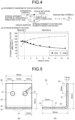
FIG. 4 illustrates a graph showing a result of a study on a stress intensity factor at a crack tip of a crack initiated in a bent portion in the background of the present invention ((a) a schematic diagram of a crack surface and (b) values of the stress intensity factor in a depth direction and a horizontal direction in the crack surface). -
FIG. 5 illustrates diagrams of a fatigue test piece used for a fatigue test in an example of the present invention ((a) the front view and (b) a cross-sectional view). -
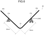
FIG. 6 is a diagram illustrating a fatigue test method in the example of the present invention. - Generally, as illustrated in
FIG. 2(a) , a fatigue crack initiated in a surface of a metal sheet grows while a semi-elliptical crack surface expands in both of a horizontal direction (direction along a surface of a metal sheet 1) and a depth direction (sheet thickness direction of the metal sheet 1), from a place where acrack 5 is initiated. Then, the crack surface reaches a back surface side of themetal sheet 1, leading to fatigue fracture. - Therefore, as illustrated in
FIG. 2(b) , an inventor observed in detail a growth process of the fatigue crack initiated on the inside of the bend of abent portion 3 obtained by bending themetal sheet 1. As a result, it was found that thecrack 5 initiated on the inside of the bend of thebent portion 3 grew in both of the depth direction (the sheet thickness direction of the metal sheet 1) and the horizontal direction (valley line direction on the inside of the bend) in thebent portion 3, immediately after initiation. Furthermore, as illustrated inFIG. 2(b) , it was found that the growth of thecrack 5 in the sheet thickness direction stopped when the depth reached approximately 1/4 of the sheet thickness t, and then thecrack 5 grew only in the horizontal direction. - In study on the cause of this findings, the inventor focused on a stress distribution in the
bent portion 3 as illustrated inFIG. 3 . As illustrated inFIG. 3(a) , immediately after themetal sheet 1 is bent, a region on the inside of the bend relative to a neutral plane is subjected to a compressive stress and a region on the outside of the bend relative to the neutral plane is subjected to tensile stress, in thebent portion 3. However, after unloading and springback of a bending moment in thebent portion 3 obtained by bending, a surface layer portion on the inside of the bend, the compressive stress is reversed to the tensile stress, as illustrated inFIG. 3(b) . In addition, the compressive stress remains at a position of approximately 1/4 of the sheet thickness t from the surface on the inside of the bend of thebent portion 3. - Therefore, it was found that the reason why the growth of the fatigue crack initiated on the inside of the bend of the
bent portion 3 in the depth direction (sheet thickness direction) stops at a depth of approximately 1/4 of the sheet thickness from the surface on the inside of the bend is due to a compressive residual stress remaining inside thebent portion 3 even after the springback. - However, when the compressive residual stress remaining in the
bent portion 3 is released for some reason (i.e., redistribution of residual stress due to yielding of a material caused by a single excessive load, or relaxation of the residual stress by heat or with time, or the like), the growth of the crack in the depth direction is resumed. At this time, the crack grows while the semi-elliptical crack surface expands in both the horizontal direction and the depth direction, and therefore, the growth of the crack in the horizontal direction to some extent may remarkably increase a crack growth rate in the depth direction, and fatigue fracture may tend to occur or brittle fracture may tend to occur. Therefore, from the viewpoint of the reliability of the part, it is desirable to take measures against such a crack. - Therefore, the inventor has intensively studied a method of suppressing the growth of the crack in the depth direction even in a state where the compressive residual stress inside the bent portion of the metal sheet is released. As a result, it was found that even in a state where the compressive residual stress remaining inside the
bent portion 3 is released by generating the compressive residual stress through application of plastic strain at predetermined intervals in the valley line direction (horizontal direction) of thebent portion 3, the growth of the crack in the depth direction can be suppressed to prevent fatigue fracture or suppress brittle fracture. - The present invention has been made on the basis of the above findings, and specifically has the following configuration.
- A fatigue crack growth suppressing method for a bent portion of a metal sheet according to a first embodiment of the present invention suppresses the growth of a fatigue crack initiated in the
bent portion 3 obtained by bending themetal sheet 1. As illustrated inFIG. 1 , in this method, plastic strain is applied at least within a range from abending start point 3a to abending end point 3b on the inside of the bend of thebent portion 3, at an interval of less than a sheet thickness t of themetal sheet 1 in a valley line direction on the inside of the bend in thebent portion 3, in a direction orthogonal to the valley line direction, generating the compressive residual stress. - In addition, as illustrated in
FIG. 1(b) , the compressive residual stress is generated by forming an indentation band 9 (seeFIG. 1(a) ) that includes a series ofindentations 7, within the range from the bendingstart point 3a to the bendingend point 3b on the inside of the bend of thebent portion 3 by needle peening using animpact pin 11. At this time, an interval d between theindentation bands 9 in the valley line direction is less than the sheet thickness t of themetal sheet 1. Theimpact pin 11 includes a tip portion 13 whose cross-section orthogonal to the valley line direction has a radius of curvature r equal to or less than a radius of curvature R on the inside of the bend of thebent portion 3. - The reason why the growth of the crack initiated on the inside of the bend of the
bent portion 3 in the valley line direction is suppressed by the present method will be described, on the basis of a result of the study on a stress intensity factor at a crack tip of the crack initiated on the inside of the bend of thebent portion 3 of themetal sheet 1 illustrated inFIG. 4 . -
FIG. 4(a) is a diagram schematically illustrating a shape of the crack surface. It is assumed that the crack initiated on the surface on the inside of the bend of thebent portion 3 of themetal sheet 1 grows while the crack surface expands into the semi-elliptical shape in both the depth direction and the horizontal direction as illustrated inFIG. 4(a) . -
FIG. 4(b) illustrates results of calculation of the stress intensity factor K at the crack tip of the crack growing in the horizontal direction (valley line direction on the inside of the bend) and the depth direction (sheet thickness direction) by using a Newman-Raju formula (see Non Patent Literature 1) represented by the following Formula (1).
- In the above Formula (1), σt is tensile stress, σb is bending stress, a is a length of the crack surface in the depth direction (sheet thickness direction), c is a horizontal length of the crack surface (distance from a crack initiation place to the crack tip in the horizontal direction), b is a sheet width of the
metal sheet 1, t is the sheet thickness of the bent portion 3 (metal sheet 1), and φ is an angle formed by a straight line L connecting the crack initiation place and the crack tip and the surface of thebent portion 3. H (a, c, t, and φ), Q (a, and c), and F (a, c, b, t, and φ) are functions given by the variables (see Non Patent Literature 1). - In
FIG. 4(b) , K(0) is a stress intensity factor that develops in the horizontal direction (valley line direction on the inside of the bend), that is, in a direction of φ = 0°. K(90) is a stress intensity factor that develops in the depth direction (sheet thickness direction), that is, in a direction of φ = 90°. In the calculation of K(0) and K(90), the sheet thickness t (= 2.8 mm), a sheet width of 50 mm, and a bending load of 100 MPa were set, and a crack depth a was set to 0.7 mm, which is 1/4 of the sheet thickness t (= 2.8 mm).FIG. 4(b) illustrates relationships between a crack surface ratio c/a, which is an index representing the shape of the semi-elliptical crack surface, and K(0) and K(90). In the above Formula (1), the influence of the compressive residual stress at a depth of approximately 1/4 of the sheet thickness t from the surface on the inside of the bend is not considered. In addition, the magnitude of the stress intensity factor calculated without considering the influence of the compressive residual stress represents the magnitude of the crack growth rate. - The graph illustrated in
FIG. 4(b) shows that in a region where the crack surface ratio c/a is c/a ≤ 2 (hereinafter, this region is referred to as a "region P"), that is, when the crack surface has an almost semicircular shape, the stress intensity factor K(0) in the horizontal direction is substantially constant having a high value and a driving force of crack extension (growth) in the horizontal direction is large. Meanwhile, it can be seen that a stress intensity factor K(90) in the depth direction is smaller than the stress intensity factor K(0) in the horizontal direction (K(90) < K(0)) and the driving force of the crack extension (growth) in the depth direction is small. - On the other hand, the graph shows that in a region where the crack surface ratio c/a is c/a > 2 (hereinafter, this region is referred to as a "region Q"), as the shape of the crack surface expands in the horizontal direction into the semi-elliptical shape (the value of c/a increases), the stress intensity factor K(0) decreases, and the driving force of crack extension in the horizontal direction also decreases. Meanwhile, it can be seen that the stress intensity factor K(90) in the depth direction is larger than the stress intensity factor K(0) in the horizontal direction (K(90) > K(0)) and the driving force of the crack extension (growth) in the depth direction increases.
- In other words, the magnitude of the driving force of the crack extension in the horizontal direction changes from the crack surface ratio c/a = 2. Assuming that the growth of the crack in the depth direction stops at a position of approximately 1/4 of the sheet thickness t, the length a of the crack surface in the depth direction is expressed as a ≈ t/4. Therefore, when the crack surface ratio c/a = 2, a relationship of 2c ≈ t is established. Furthermore, assuming that the crack grows symmetrically in the horizontal direction, 2c is the width of the crack surface in the horizontal direction. Therefore, when the crack surface ratio c/a = 2, the width (= 2c) of the crack surface in the horizontal direction is substantially the same as the sheet thickness t of the
metal sheet 1. - On the basis of the above result of the study, a concept of suppressing the growth of the crack initiated on the inside of the bend of the
bent portion 3 will be described. - As described above, when the compressive residual stress remains inside the
bent portion 3, the growth of the crack in the depth direction stops at the position of approximately 1/4 of the sheet thickness t from the surface on the inside of the bend, and the crack mainly grows only in the horizontal direction. Therefore, the shape of the crack surface extends in the horizontal direction into the semi-elliptical shape (crack surface ratio c/a > 2, the region Q inFIG. 4(b) ). Then, as the shape of the crack surface expands in the horizontal direction (as the crack surface ratio c/a increases), the stress intensity factor K(0) in the horizontal direction decreases, and the crack growth rate in the horizontal direction gradually decreases. Meanwhile, although the crack does not grow in the depth direction due to the compressive residual stress remaining inside, when the residual stress is ignored, the stress intensity factor K(90) in the depth direction is in a state (K(90) > K(0)) where the stress intensity factor K(90) is larger than the stress intensity factor K(0) in the horizontal direction. In such a state, when the compressive residual stress inside thebent portion 3 is released for some reason as described above, the growth of the crack in the depth direction is resumed. Then, the stress intensity factor K(90) in the depth direction governs a fracture phenomenon such as fracture toughness, the crack growth rate in the depth direction remarkably increases, and brittle fracture is likely to occur. - Therefore, in order to suppress or prevent the growth of the crack in the depth direction in a state where the residual stress is relaxed as described above, the growth of the crack in the horizontal direction is preferably stopped before the shape of the crack surface is extended in the horizontal direction into the semi-elliptical shape, that is, in a state where the stress intensity factor K(90) in the depth direction is smaller than the stress intensity factor K(0) in the horizontal direction (K(90) < K(0), the region P in
FIG. 4(b) ). - In other words, as illustrated in
FIG. 4(b) , in order to stop the growth of the crack in the horizontal direction in the region P where the growth of the crack satisfies c/a < 2, that is, a crack width 2c less than the sheet thickness t (2c < t) is satisfied, theindentation bands 9 are formed in the valley line direction of thebent portion 3 at an interval less than the sheet thickness t to introduce the compressive residual stress. Therefore, assuming that thecrack 5 grows symmetrically in the horizontal direction, when thecrack 5 grows to reach thefirst indentation band 9, the crack width 2c of less than the sheet thickness t is satisfied, and the value of the stress intensity factor K(90) in the depth direction does not exceed the value of the stress intensity factor K(0) in the horizontal direction when c/a = 2. Therefore, it is possible to suppress the growth of the crack in the depth direction. - As described above, when the compressive residual stress inside the
bent portion 3 is released, it is possible to suppress fatigue fracture due to rapid growth of thecrack 5 in the depth direction. Furthermore, preventing the stress intensity factor K(90) in the depth direction at an end of the crack surface from increasing relative to the stress intensity factor K(0) in the horizontal direction, it is also possible to suppress the brittle fracture caused by the crack initiated in thebent portion 3. - The above description has been made of the compressive residual stress inside the
bent portion 3 being released, but even when the compressive residual stress remains unreleased, it is possible to suppress the growth of the crack in the valley line direction, suppressing the fatigue fracture to improve the fatigue life. - In the first embodiment, as described above, the compressive residual stress of the
bent portion 3 is generated by forming theindentation band 9, which has a series ofindentations 7, on the inside of the bend of thebent portion 3 by the needle peening using the impact pin and applying plastic strain. Theimpact pin 11 preferably includes the tip portion 13 whose cross-section orthogonal to the valley line direction has the radius of curvature r equal to or smaller than the radius of curvature R of the in the of thebent portion 3. - This is because if the radius of curvature r of the tip portion 13 of the
impact pin 11 is larger than the radius of curvature R of thebent portion 3, the tip portion 13 of theimpact pin 11 cannot apply direct impact to thebent portion 3 and compressive residual stress cannot be appropriately generated in thebent portion 3. - In part of the inside of the bend of the
bent portion 3, buckling deformation occurs during bending, and the radius of curvature is locally extremely reduced, in some cases. However, the radius of curvature R of thebent portion 3 preferably has a macroscopic radius of curvature, except for the radius of curvature of thebent portion 3 globally changed due to buckling. - Furthermore, against the problems (b) and (c) in the technology described in
Patent Literature 4 described above, impact is applied by theimpact pin 11 having the radius of curvature r smaller than the radius of curvature on the inside of the bend of thebent portion 3. This configuration makes it possible to suppress deformation of themetal sheet 1 and a change in the bending angle of thebent portion 3, and at the same time, to appropriately introduce the compressive residual stress into thebent portion 3. - In addition, the range in which the
indentation band 9 is formed on the inside of the bend of thebent portion 3 in the direction orthogonal to the valley line direction may be whole or part of the range from the bending start point to the bending end point on the inside of the bend. Each of the bending start point and the bending end point means an end of curvature on the inside of the bend of thebent portion 3. - At this time, when a crack or wrinkles are apparent or a crack initiation position according to a condition or the like of stress applied to the metal sheet is apparent, in the width direction of the
bent portion 3, it is not necessary to perform treatment over the entire range of thebent portion 3 on the inside of the bend in the valley line direction. Theindentation bands 9 are preferably formed only around the crack initiation position to apply plastic strain so that the compressive residual stress may be generated. - The lower limit of the interval d between the
indentation bands 9 in the valley line direction on the inside of the bend of thebent portion 3 is not particularly defined, but is preferably large from the viewpoint of productivity. When there is an allowable crack length, such as a life required for a part obtained by bending a metal sheet, an allowable crack length as a part, or a lower limit of the length of a crack that can be found in periodic inspection, the smaller of the crack length and the sheet thickness is preferably set as the lower limit. - In the present invention, simultaneous needle peening using a plurality of impact pins may be employed, and further, the needle peening can be combined with an automatic construction method using a robot arm or the like may promise improvement in productivity. Furthermore, for a part having many bent portions, such as an automotive part, application of this treatment to the entire region of the bent portions reduces productivity. Therefore, it is preferable to limit application of the treatment, only to a place where the radius of curvature of the bent portion is smaller, or a place where the fatigue fracture on the inside of the bend may occur, found in advance by a fatigue test, stress analysis, or the like.
- Furthermore, the present invention preferably generates the compressive residual stress in the bent portion to suppress the growth of the crack in the valley line direction of the bent portion. Therefore, the method of generating the compressive residual stress is not limited to the needle peening, and similar treatment such as laser peening, shot peening, or cold spray may be employed. When the shot peening is employed, masking a position other than a position where the indentations are desired to introduce so as not to cause unnecessary plastic deformation provides the equivalent effect. These methods are methods to apply impact on materials to generate plastic strain, causing the compressive residual stress. In the laser peening, plastic strain is applied by impact on the bent portion caused by using a shock wave generated upon laser irradiation, and in each of the shot peening and the cold spray, plastic strain is applied by impact on the bent portion caused by spraying a projection material.
- When the bending of the metal sheet follows axial tension and compression, not by pure bending, the position in the sheet thickness direction where the compressive residual stress is introduced moves, but also in this case, the crack stops at the position of the compressive residual stress. Therefore, when the position of the compressive residual stress is not so different from the position of 1/4 of the sheet thickness t, treatment is preferably performed under the condition in which a relationship between the depth a of the compressive residual stress and the horizontal length c of the crack surface satisfies 2c > 4a.
- When a position in the depth direction where the compressive residual stress is introduced by the springback is greatly separated from the position of 1/4 of the sheet thickness, recalculation is preferably performed by the above method to determine the interval d at which the needle peening is performed on the basis of the value of c/a at which K(0) decreases.
- As described above, in the present invention, the fatigue life of the part having the bent portion obtained by bending the metal sheet can be effectively improved. Furthermore, according to the present invention, the peening is not required for the entire surface of the inside of the bend in the bent portion, and therefore, improvement in productivity is promising, and the effect of improving the fatigue life given by the compressive residual stress or work-hardening due to local plastic strain on the inner side of the bend is also promising.
- Furthermore, according to the present invention, even when no crack is originally initiated on the inside of the bend of the bent portion, microscopic irregularities such as wrinkles are smoothed, and therefore, an effect of reducing microscopic stress concentration is promising. In addition, use of the impact pin having the tip portion with a small radius of curvature makes it possible to reduce the impact load required to deform the metal sheet and form the indentation band. This configuration suppresses a reaction force for stable construction, and makes it possible not only to suppress macroscopic deformation of the whole of a part that may occur when the method described in
Patent Literature 4 is applied to the part having the bent portion of the metal sheet, but also to apply the method to a production line using a robot arm or the like. - In addition, in the present invention, it is possible to eliminate the possibility that the impact pin does not make contact with the surface on the inside of the bend of the bent portion and impact is not sufficiently applied. Furthermore, when the present invention is applied to the manufacture of the automotive part, an additional press mold for performing bending as in the method described in
Patent Literature 1 is not required, and the present invention is also applicable to the burring portion as in a method described inPatent Literature 2. Furthermore, a scattering prevention container required for shot peening as in the method described inPatent Literature 3 is not required. - As illustrated in
FIG. 1 , an automotive part according to a second embodiment of the present invention includes thebent portion 3 obtained by bending themetal sheet 1 to suppress the growth of the fatigue crack in thebent portion 3. The automotive part includes theindentation bands 9, each of which includes a series of theindentations 7 obtained by the needle peening, at least within a range from the bendingstart point 3a to the bendingend point 3b on the inside of the bend of thebent portion 3, at an interval of less than the sheet thickness of themetal sheet 1 in the valley line direction of thebent portion 3, in a direction orthogonal to the valley line direction. - In the automotive part according to the second embodiment as well, similarly to the fatigue crack growth suppressing method for the bent portion of the metal sheet according to the first embodiment of the present invention described above, the
indentation bands 9 are formed by the needle peening at an interval less than the sheet thickness in the valley line direction of thebent portion 3 to apply the compressive residual stress, suppressing the growth of thecrack 5 in the valley line direction before the crack width reaches the size of the sheet thickness. This configuration makes it possible to suppress fatigue fracture due to rapid growth of the crack in the sheet thickness direction, when the compressive residual stress remaining inside thebent portion 3 is released. Furthermore, the brittle fracture caused by thecrack 5 initiated in thebent portion 3 can be suppressed. - Furthermore, in the automotive part according to the second embodiment, even when the compressive residual stress inside the
bent portion 3 remains unreleased, the growth of thecrack 5 in the valley line direction can be suppressed, and therefore, the fatigue fracture can be prevented to improve the fatigue life. - Plastic strain is applied to the
bent portion 3 in the automotive part according to the second embodiment by the needle peening. In the automotive part according to the present invention, the plastic strain applied to the bent portion by the needle peening is employed, but the plastic strain may be applied to the bent portion by treatment such as laser peening, shot peening, or cold spray. - An experiment that was conducted for confirming the functions and effects of the present invention will be described below.
- In the present example, a fatigue test was performed on a
fatigue test piece 21 illustrated inFIG. 5 as a test object, for evaluation of fatigue strength. - A hot rolled steel sheet having a sheet thickness of 2.9 mm and a yield strength grade of 850 MPa was cut into 200 mm × 50 mm as a sample, the sample was subjected to bending by using a press brake (bending machine) including a bending tool (punch) having a tip portion with a radius of curvature of 3 mm, and the
fatigue test piece 21 was prepared. Thefatigue test piece 21 includes abent portion 23 that has a radius of curvature R = 2 mm on the inside of the bend andpiece portions bent portion 23, and thepiece portions hole portions - Next, as illustrated in
FIGS. 1(a) and 1(b) , thebent portion 23 of thefatigue test piece 21 was subjected to needle peening to formindentation bands 29 at a predetermined interval d in the valley line direction on the inside of the bend. The radius of curvature r of the tip portion of theimpact pin 11 used for the needle peening was set to r = 0.2 mm smaller than the radius of curvature R = 2 mm in a cross-section of thebent portion 23 taken in the valley line direction. - Subsequently, the fatigue test was performed on the
fatigue test piece 21 obtained by needle peening of thebent portion 23, under a boundary condition illustrated inFIG. 6 . In the fatigue test, as illustrated inFIG. 6 , thehole portion 27a (FIG. 6 ) of onepiece portion 25a of thefatigue test piece 21 was fixed as a fixing point, and a cyclic load (load of 2.3 kN and repetition frequency of 10 Hz) was applied with thehole portion 27b of theother piece portion 25b as a load input point. - Then, a penetrant inspection test for the
bent portion 23 was performed every 100,000 load input cycles to measure the growth of the crack initiated in thebent portion 23. When a crack of 2.8 mm or more is initiated, the test was finished, and the fatigue test was finished. In addition, 2,000,000 cyclic load cycles was defined as a fatigue limit, thefatigue test piece 21 that has reached the fatigue limit was determined to be acceptable, and the fatigue test was finished. - In the present example, a fatigue test was performed on a
fatigue test piece 21 having a changed interval d between theindentation bands 29, and 2-mm and 2.8-mmfatigue test pieces 21 each having an interval d less than the sheet thickness of themetal sheet 1 within the range of the present invention were defined as invention example 1 and invention example 2. In addition, for comparison, 3-mm and 4-mmfatigue test pieces 21 having an interval d between theindentation bands 29 equal to or more than the sheet thickness of themetal sheet 1 out of the range of the present invention were used as comparative example 1 and comparative example 2, and afatigue test piece 21 in which thebent portion 23 was not subjected to the peening and theindentation band 29 was not formed was used as comparative example 3. Table 1 shows the intervals d between theindentation bands 29 formed in thefatigue test pieces 21 and results of the fatigue tests.Table 1 Interval d (mm) Cycles for finish of fatigue test Acceptable/unacceptable Invention example 1 2 2,000,000 cycles Acceptable Invention example 2 2.8 2,000,000 cycles Acceptable Comparative example 1 3 1,500,000 cycles Unacceptable Comparative example 2 4 500,000 cycles Unacceptable Comparative example 3 No peening 200,000 cycles Unacceptable - Each of invention example 1 and invention example 2 reached the fatigue limit without a crack of 2.8 m or more after 2,000,000 cycles, and was determined to be acceptable. On the other hand, a crack of 2.8 mm or more was initiated in comparative example 1 and comparative example 2 each having an interval d between the
indentation bands 29 out of the range of the present invention, after 1,500,000 cycles and 500,000 cycles, respectively, and the crack was initiated in comparative example 3 without theindentation band 29, after 200,000 cycles, and any of the comparative examples was determined to be unacceptable. - As described above, according to the present invention, it was shown that the growth of the fatigue crack on the inside of the bend of the bent portion obtained by bending the metal sheet can be suppressed and the fatigue life can be improved.
- According to the present invention, it is possible to provide the fatigue crack growth suppressing method for a bent portion of a metal sheet, the method being applicable to a bent portion after bending without increasing the manufacturing cost of the bent portion of the metal sheet, the method being configured to suppress the growth of a fatigue crack in the bent portion without decreasing the productivity or changing the bending angle of the whole of a part or the bent portion. In addition, according to the present invention, it is possible to provide the automotive part that has a bent portion obtained by bending a metal sheet, the bent portion being suppressed in growth of the fatigue crack.
-
- 1 METAL SHEET
- 3 BENT PORTION
- 3a BENDING START POINT
- 3b BENDING END POINT
- 5 CRACK
- 7 INDENTATION
- 9 INDENTATION BAND
- 11 IMPACT PIN
- 13 TIP PORTION
- 21 FATIGUE TEST PIECE
- 23 BENT PORTION
- 25a, 25b PIECE PORTION
- 27a, 27b HOLE PORTION
- 29 INDENTATION BAND
Claims (3)
- A fatigue crack growth suppressing method for a bent portion of a metal sheet for suppressing growth of a fatigue crack in the bent portion obtained by bending the metal sheet, comprising
generating a compressive residual stress by applying plastic strain at least within a range from a bending start point to a bending end point on an inside of a bend of the bent portion, at an interval of less than a sheet thickness of the metal sheet in a valley line direction of the bent portion, in a direction orthogonal to the valley line direction. - The fatigue crack growth suppressing method for a bent portion of a metal sheet according to claim 1, whereinthe compressive residual stress is generated by forming an indentation band including a series of indentations, on the inside of the bend of the bent portion through needle peening using an impact pin, anda radius of curvature of a tip portion of the impact pin in a cross-section orthogonal to the valley line direction is equal to or less than a radius of curvature of the bent portion.
- An automotive part comprising:a bent portion obtained by bending a metal sheet, the bent portion being suppressed in growth of a fatigue crack; andan indentation band including a series of indentations obtained by needle peening using an impact pin in a direction orthogonal to a valley line direction, the indentation band being positioned at least within a range from a bending start point to a bending end point on an inside of a bend of the bent portion, and the indentations being provided at an interval of less than a sheet thickness of the metal sheet along the valley line direction of the bent portion.
Applications Claiming Priority (2)
| Application Number | Priority Date | Filing Date | Title |
|---|---|---|---|
| JP2021204716A JP7251605B1 (en) | 2021-12-17 | 2021-12-17 | METHOD FOR SUPPRESSING FATIGUE CRACK PROGRESSION OF BENDED METAL PLATE AND AUTOMOBILE PARTS |
| PCT/JP2022/031204 WO2023112390A1 (en) | 2021-12-17 | 2022-08-18 | Method for suppressing fatigue crack progression in bent section of metal plate and automobile component |
Publications (3)
| Publication Number | Publication Date |
|---|---|
| EP4431202A1 true EP4431202A1 (en) | 2024-09-18 |
| EP4431202A4 EP4431202A4 (en) | 2025-02-19 |
| EP4431202B1 EP4431202B1 (en) | 2026-04-22 |
Family
ID=85779570
Family Applications (1)
| Application Number | Title | Priority Date | Filing Date |
|---|---|---|---|
| EP22906926.5A Active EP4431202B1 (en) | 2021-12-17 | 2022-08-18 | Fatigue crack growth suppressing method for bent portion of metal sheet, and automotive part |
Country Status (7)
| Country | Link |
|---|---|
| US (1) | US20250041924A1 (en) |
| EP (1) | EP4431202B1 (en) |
| JP (1) | JP7251605B1 (en) |
| KR (1) | KR20240112877A (en) |
| CN (1) | CN118302260A (en) |
| MX (1) | MX2024006988A (en) |
| WO (1) | WO2023112390A1 (en) |
Families Citing this family (2)
| Publication number | Priority date | Publication date | Assignee | Title |
|---|---|---|---|---|
| JP7626164B2 (en) | 2023-05-31 | 2025-02-04 | 住友金属鉱山株式会社 | Lithium niobate single crystal, method for producing lithium niobate single crystal, and AR glass |
| EP4656305A1 (en) * | 2024-05-29 | 2025-12-03 | VARTA Microbattery GmbH | Method for producing a cup for a housing of an electrochemical energy storage element |
Family Cites Families (12)
| Publication number | Priority date | Publication date | Assignee | Title |
|---|---|---|---|---|
| JPS52133864A (en) * | 1976-05-04 | 1977-11-09 | Nippon Electric Co | Mold for vvbend processing of metal plate material |
| JPH07155841A (en) * | 1993-12-07 | 1995-06-20 | Honda Motor Co Ltd | Springback straightening method |
| JPH08117879A (en) * | 1994-08-29 | 1996-05-14 | Toyota Motor Corp | Press working method |
| JP4075187B2 (en) * | 1999-02-05 | 2008-04-16 | トヨタ自動車株式会社 | Shot peening method for metal plate |
| JP4441641B1 (en) * | 2008-11-25 | 2010-03-31 | 国立大学法人名古屋大学 | Fatigue crack repair method for steel structures |
| JP6115554B2 (en) * | 2014-12-08 | 2017-04-19 | トヨタ自動車株式会社 | Shot peening method |
| JP7066315B2 (en) * | 2016-09-29 | 2022-05-13 | 日本製鉄株式会社 | Burling processing equipment, burring processing method, metal parts manufacturing method, burring processed products and metal parts |
| JP2018051608A (en) * | 2016-09-29 | 2018-04-05 | 新日鐵住金株式会社 | Coining method, and coining device for product processed by burring method and metal component |
| GB2561564B (en) * | 2017-04-18 | 2019-12-18 | Univ Of Hertfordshire Higher Education Corporation | A method of reducing spring back in a metallic material |
| JP2019178382A (en) * | 2018-03-30 | 2019-10-17 | 株式会社ワイテック | Manufacturing method of steel product formed by bending |
| JP6696604B1 (en) * | 2019-03-08 | 2020-05-20 | Jfeスチール株式会社 | Needle peening method |
| JP2021045783A (en) * | 2019-09-20 | 2021-03-25 | ジヤトコ株式会社 | Press die and manufacturing method of work-piece |
-
2021
- 2021-12-17 JP JP2021204716A patent/JP7251605B1/en active Active
-
2022
- 2022-08-18 WO PCT/JP2022/031204 patent/WO2023112390A1/en not_active Ceased
- 2022-08-18 KR KR1020247020040A patent/KR20240112877A/en active Pending
- 2022-08-18 MX MX2024006988A patent/MX2024006988A/en unknown
- 2022-08-18 CN CN202280081513.2A patent/CN118302260A/en active Pending
- 2022-08-18 US US18/716,790 patent/US20250041924A1/en active Pending
- 2022-08-18 EP EP22906926.5A patent/EP4431202B1/en active Active
Also Published As
| Publication number | Publication date |
|---|---|
| EP4431202A4 (en) | 2025-02-19 |
| JP7251605B1 (en) | 2023-04-04 |
| KR20240112877A (en) | 2024-07-19 |
| WO2023112390A1 (en) | 2023-06-22 |
| US20250041924A1 (en) | 2025-02-06 |
| MX2024006988A (en) | 2024-06-19 |
| EP4431202B1 (en) | 2026-04-22 |
| CN118302260A (en) | 2024-07-05 |
| JP2023090005A (en) | 2023-06-29 |
Similar Documents
| Publication | Publication Date | Title |
|---|---|---|
| EP4431202B1 (en) | Fatigue crack growth suppressing method for bent portion of metal sheet, and automotive part | |
| US11590591B2 (en) | Press die designing method using an index value obtained from two stress gradients in sheet thickness direction and gradient of surface stress distribution in direction | |
| EP3939712B1 (en) | Pressed component manufacturing method | |
| EP3260215A1 (en) | Press forming method and press forming mold | |
| EP3272437B1 (en) | Press-forming method and press-forming tool | |
| EP3939713B1 (en) | Stretch flange crack evaluation method, metal sheet selection method, press die design method, component shape design method, and pressed component manufacturing method | |
| JPH08117879A (en) | Press working method | |
| EP4382222A1 (en) | Method for improving delayed fracture characteristics of steel sheet, method for producing blank, method for producing press-formed article, and press-formed article | |
| JP7318602B2 (en) | METHOD FOR MANUFACTURE OF TEST SPECIMEN AND METHOD FOR EVALUATION OF DELAYED FRACTURE CHARACTERISTICS OF HIGH-STRENGTH STEEL STEEL | |
| Radonjic et al. | Approaches for springback reduction when forming ultra high-strength sheet metals | |
| EP4239313B1 (en) | Delayed fracture characteristic evaluation method and program | |
| EP4410473A1 (en) | Method for suppressing fatigue crack progression in bent section of metal plate and automobile component | |
| EP4556134A1 (en) | Method for manufacturing press-molded article | |
| EP4389314A1 (en) | Shape change prediction method for press-formed product | |
| EP4112201B1 (en) | Press forming method | |
| US9573247B2 (en) | Shot peening method | |
| JP4510572B2 (en) | Manufacturing method for automotive parts having punched end faces with excellent fatigue characteristics | |
| US11759837B1 (en) | Systems and methods for launch vehicle dome manufacturing | |
| Radonjic et al. | Compensating the springback of ultra-high-strength steel parts by specific stress superposition during sheet metal forming | |
| Jawad | Design modification in a multi-stage deep drawing process | |
| EP4268987B1 (en) | Press forming method | |
| JP2024028215A (en) | Method for manufacturing press parts, metal plate for press processing, and method for manufacturing the same | |
| US20250237281A1 (en) | Method for manufacturing impact energy absorbing component, and impact energy absorbing component | |
| Liewald et al. | Chances and risks when using high strength steel sheets in structural parts of modern car bodies | |
| JP2005034906A (en) | Method for improving dent-resistance of steel sheet |
Legal Events
| Date | Code | Title | Description |
|---|---|---|---|
| STAA | Information on the status of an ep patent application or granted ep patent |
Free format text: STATUS: THE INTERNATIONAL PUBLICATION HAS BEEN MADE |
|
| PUAI | Public reference made under article 153(3) epc to a published international application that has entered the european phase |
Free format text: ORIGINAL CODE: 0009012 |
|
| STAA | Information on the status of an ep patent application or granted ep patent |
Free format text: STATUS: REQUEST FOR EXAMINATION WAS MADE |
|
| 17P | Request for examination filed |
Effective date: 20240613 |
|
| AK | Designated contracting states |
Kind code of ref document: A1 Designated state(s): AL AT BE BG CH CY CZ DE DK EE ES FI FR GB GR HR HU IE IS IT LI LT LU LV MC MK MT NL NO PL PT RO RS SE SI SK SM TR |
|
| A4 | Supplementary search report drawn up and despatched |
Effective date: 20250121 |
|
| RIC1 | Information provided on ipc code assigned before grant |
Ipc: C21D 7/04 20060101ALI20250115BHEP Ipc: B21D 53/88 20060101ALI20250115BHEP Ipc: B21D 31/06 20060101ALI20250115BHEP Ipc: C21D 7/06 20060101ALI20250115BHEP Ipc: B23P 9/04 20060101ALI20250115BHEP Ipc: B21D 5/01 20060101ALI20250115BHEP Ipc: B21D 22/26 20060101AFI20250115BHEP |
|
| DAV | Request for validation of the european patent (deleted) | ||
| DAX | Request for extension of the european patent (deleted) | ||
| GRAP | Despatch of communication of intention to grant a patent |
Free format text: ORIGINAL CODE: EPIDOSNIGR1 |
|
| STAA | Information on the status of an ep patent application or granted ep patent |
Free format text: STATUS: GRANT OF PATENT IS INTENDED |
|
| INTG | Intention to grant announced |
Effective date: 20251222 |
|
| GRAS | Grant fee paid |
Free format text: ORIGINAL CODE: EPIDOSNIGR3 |
|
| GRAA | (expected) grant |
Free format text: ORIGINAL CODE: 0009210 |
|
| STAA | Information on the status of an ep patent application or granted ep patent |
Free format text: STATUS: THE PATENT HAS BEEN GRANTED |
|
| AK | Designated contracting states |
Kind code of ref document: B1 Designated state(s): AL AT BE BG CH CY CZ DE DK EE ES FI FR GB GR HR HU IE IS IT LI LT LU LV MC MK MT NL NO PL PT RO RS SE SI SK SM TR |
|
| REG | Reference to a national code |
Ref country code: CH Ref legal event code: F10 Free format text: ST27 STATUS EVENT CODE: U-0-0-F10-F00 (AS PROVIDED BY THE NATIONAL OFFICE) Effective date: 20260422 Ref country code: GB Ref legal event code: FG4D |
|
| REG | Reference to a national code |
Ref country code: DE Ref legal event code: R096 Ref document number: 602022035292 Country of ref document: DE |