EP4431185A1 - Liquid handling cover for a microfluidic device - Google Patents
Liquid handling cover for a microfluidic device Download PDFInfo
- Publication number
- EP4431185A1 EP4431185A1 EP23162537.7A EP23162537A EP4431185A1 EP 4431185 A1 EP4431185 A1 EP 4431185A1 EP 23162537 A EP23162537 A EP 23162537A EP 4431185 A1 EP4431185 A1 EP 4431185A1
- Authority
- EP
- European Patent Office
- Prior art keywords
- liquid
- outlet
- inlet
- microfluidic device
- liquid handling
- Prior art date
- Legal status (The legal status is an assumption and is not a legal conclusion. Google has not performed a legal analysis and makes no representation as to the accuracy of the status listed.)
- Pending
Links
Images



Classifications
-
- B—PERFORMING OPERATIONS; TRANSPORTING
- B01—PHYSICAL OR CHEMICAL PROCESSES OR APPARATUS IN GENERAL
- B01L—CHEMICAL OR PHYSICAL LABORATORY APPARATUS FOR GENERAL USE
- B01L3/00—Containers or dishes for laboratory use, e.g. laboratory glassware; Droppers
- B01L3/50—Containers for the purpose of retaining a material to be analysed, e.g. test tubes
- B01L3/502—Containers for the purpose of retaining a material to be analysed, e.g. test tubes with fluid transport, e.g. in multi-compartment structures
- B01L3/5027—Containers for the purpose of retaining a material to be analysed, e.g. test tubes with fluid transport, e.g. in multi-compartment structures by integrated microfluidic structures, i.e. dimensions of channels and chambers are such that surface tension forces are important, e.g. lab-on-a-chip
- B01L3/50273—Containers for the purpose of retaining a material to be analysed, e.g. test tubes with fluid transport, e.g. in multi-compartment structures by integrated microfluidic structures, i.e. dimensions of channels and chambers are such that surface tension forces are important, e.g. lab-on-a-chip characterised by the means or forces applied to move the fluids
-
- B—PERFORMING OPERATIONS; TRANSPORTING
- B01—PHYSICAL OR CHEMICAL PROCESSES OR APPARATUS IN GENERAL
- B01L—CHEMICAL OR PHYSICAL LABORATORY APPARATUS FOR GENERAL USE
- B01L3/00—Containers or dishes for laboratory use, e.g. laboratory glassware; Droppers
- B01L3/56—Labware specially adapted for transferring fluids
- B01L3/563—Joints or fittings; Separable fluid transfer means to transfer fluids between at least two containers, e.g. connectors
-
- B—PERFORMING OPERATIONS; TRANSPORTING
- B01—PHYSICAL OR CHEMICAL PROCESSES OR APPARATUS IN GENERAL
- B01L—CHEMICAL OR PHYSICAL LABORATORY APPARATUS FOR GENERAL USE
- B01L2200/00—Solutions for specific problems relating to chemical or physical laboratory apparatus
- B01L2200/02—Adapting objects or devices to another
- B01L2200/026—Fluid interfacing between devices or objects, e.g. connectors, inlet details
- B01L2200/027—Fluid interfacing between devices or objects, e.g. connectors, inlet details for microfluidic devices
-
- B—PERFORMING OPERATIONS; TRANSPORTING
- B01—PHYSICAL OR CHEMICAL PROCESSES OR APPARATUS IN GENERAL
- B01L—CHEMICAL OR PHYSICAL LABORATORY APPARATUS FOR GENERAL USE
- B01L2300/00—Additional constructional details
- B01L2300/04—Closures and closing means
- B01L2300/041—Connecting closures to device or container
-
- B—PERFORMING OPERATIONS; TRANSPORTING
- B01—PHYSICAL OR CHEMICAL PROCESSES OR APPARATUS IN GENERAL
- B01L—CHEMICAL OR PHYSICAL LABORATORY APPARATUS FOR GENERAL USE
- B01L2300/00—Additional constructional details
- B01L2300/04—Closures and closing means
- B01L2300/046—Function or devices integrated in the closure
-
- B—PERFORMING OPERATIONS; TRANSPORTING
- B01—PHYSICAL OR CHEMICAL PROCESSES OR APPARATUS IN GENERAL
- B01L—CHEMICAL OR PHYSICAL LABORATORY APPARATUS FOR GENERAL USE
- B01L2400/00—Moving or stopping fluids
- B01L2400/04—Moving fluids with specific forces or mechanical means
- B01L2400/0475—Moving fluids with specific forces or mechanical means specific mechanical means and fluid pressure
Definitions
- the present invention relates to the field of microfluidic devices. More specifically, it relates to a liquid handling cover for a microfluidic device operating by hydrostatic pressure.
- Microfluidic devices are well-established technologies for chemical, biological, pharmacological, biochemical and other assays, and have in common that a liquid is received from an inlet port and is caused to pass through at least part of the device.
- the present invention concerns the types of microfluidic devices which have not only an inlet port, but also an outlet port from which liquid is extracted, the liquid flow being caused by a difference in hydrostatic pressure between the inlet and the outlet.
- document EP1724017 discloses a liquid feeding system for a microfluidic device in which an interface is provided which is placed between the device's ports and pipettes, the ports and the pipettes being sealed together.
- the flow is induced by adjusting the inlet and outlet port volumes and/or format, with the device being configured for passive continuous flow through a single channel as liquid moves from the inlet port to the outlet port until equilibrium is reached.
- equilibrium typically takes a matter of a few minutes to be reached, unless liquid is added to the inlet port and removed from the outlet port.
- a microfluidic device is prefilled with liquid and positioned on a tilting stage, the flow being adjusted via the tilting angle and sometimes also the frequency of variations of the tilting angle.
- These arrangements generate hydrostatic pressure by positioning one port above the other, and once equilibrium is reached, the angle of tilt can be reversed and the flow occurs in the opposite direction. Examples of such arrangements are given in WO2017/068376 , US2020/070165 and WO2021/026373 .
- the aim of the present invention is hence to at least partially overcome the above-mentioned drawbacks of the prior art.
- the invention relates to a liquid handling cover as defined in claim 1.
- This liquid handling cover is adapted to be placed over a microfluidic device comprising at least one inlet port and at least one outlet port, said liquid handling cover comprising:
- This arrangement enables continuous unidirectional flow in microfluidic channels of a device without requiring water-tight or air-tight sealing, eliminating all risk of leakage or irregularities typically associated with active flow interfaces. It is compatible with many kinds of microfluidic devices as long as they present at least one inlet port and one outlet port connected by at least one microfluidic channel, and permits them to be operated with continuous flow for relatively long periods (hours, days, weeks, months or even longer). Furthermore, it requires little or no modification to the microfluidic device, which may hence be of a standard type. Further advantages are discussed below.
- each of said inlet channel and said outlet channel are arranged to enter into the corresponding port, i.e. the inlet channel into the inlet port, and the outlet channel into the outlet port, said outlet channel extending further into said outlet port than said inlet channel extends into said inlet port.
- the liquid handling cover may further comprise an optical window, which may be a simple opening or a transparent portion, permitting at least part of said microfluidic device to be seen.
- an optical window which may be a simple opening or a transparent portion, permitting at least part of said microfluidic device to be seen.
- said liquid handling cover may be adapted to cooperate with said microfluidic device in a manner permitting sterility, for instance with sufficient contact around the edge thereof or even an air and/or liquid tight sealing thereto, although this does not have to be the case and it may have a clearance therewith.
- sterility for instance with sufficient contact around the edge thereof or even an air and/or liquid tight sealing thereto, although this does not have to be the case and it may have a clearance therewith.
- At least one liquid reservoir may be provided on a surface of said principal portion facing away from said microfluidic device, enabling liquid to be placed therein to increase the humidity proximate to the microfluidic device, to minimize evaporation of liquid therefrom.
- the liquid handling cover may comprise an array of said inlet channels and said outlet channels adapted to cooperate with a plurality of said microfluidic devices such that they can be operated in parallel or sequentially.
- the liquid handling cover of the invention can be incorporated into a liquid handling system for a microfluidic device, which further comprises at least one pump adapted to cause liquid to move from a reservoir to said inlet channel and to cause liquid to be aspirated from said outlet port via said outlet channel.
- the at least one pump comprises:
- the at least one pump is a single pump adapted to cause liquid to be moved from an inlet reservoir to said inlet channel, and to cause liquid to be moved from said outlet channel into an outlet reservoir, a controllable valve being associated with each reservoir.
- controllable valves may be arranged either:
- said at least one pump is a single pump and said reservoir is a recirculation reservoir adapted to receive liquid from said outlet channel and to provide liquid to said inlet channel, enabling a sample to be circulated continuously.
- Figure 1 illustrates a first embodiment of a liquid handling cover 1 according to the invention, together with other components of a liquid handling system 100 and a microfluidic device 200 with which the liquid handling cover 1 is intended to cooperate.
- Liquid handling cover 1 comprises a principal portion 3 intended to be positioned above and facing said microfluidic device 200, and optional lateral supports 5 to support it.
- the exact shape of the principal portion 3 and optional lateral supports 5 can be adapted according to need, based on the dimensions of the microfluidic device 200, whether the cover 1 is intended to serve a single or multiple microfluidic devices 200, whether these are provided in a well plate or other support, and so on.
- the principal portion 3 is arranged substantially parallel to the microfluidic device, but this does not strictly need to be the case.
- an optical window 7 arranged so as to allow an operator to see at least part of the microfluidic device 200, for instance to be able to visualize a sample or a colour changing element of this latter, and so on.
- This optical window 7 can either be simply an opening, or may be constituted by a piece of transparent material such as glass or a transparent polymer.
- a liquid reservoir 9 can be provided on an upper surface of the principal portion 3, in order to contribute to maintaining a humid environment in the proximity of the cover 1, so as to help reduce evaporation in the microfluidic device 200.
- Cover 1 further comprises an inlet channel 11 extending from an inlet liquid connector 11 a in the principal portion 3 in the direction of the microfluidic device 200, namely towards an inlet port 201 that serves as an inlet reservoir, and an outlet channel 13, which extends from an outlet liquid connector 13a second port 13a such that the distal extremity of outlet channel 13 is positioned down within an outlet port 203 serving as an outlet reservoir.
- a clearance is present between each of the channels 11, 13 and the respective ports 201, 203, that is to say that the channels 11, 13 are not sealed to the ports 201, 203.
- the distal extremity of inlet channel 11 may be situated completely above the inlet port 201, or may extend into this latter, according to the needs of the constructor.
- a height difference h between the level of liquid in the two ports 201, 203 can be generated, which causes liquid L to flow unidirectionally from the inlet port 201 to the outlet port 203 along a microfluidic channel 205, and through any functional elements of the microfluidic device 200.
- microfluidic device is not important for the present invention, and need not be discussed at length, but microfluidic devices for chemical, biochemical, pharmaceutical and biological assays can be used, insofar as they have both at least one inlet port 201 and at least one outlet port 203.
- the system 100 may be operated either continuously, or by alternately aspirating and injecting liquid L, the liquid flow through the microfluidic device 200.
- a microfluidic device 200 which is prefilled with liquid L to a certain height is provided and the cover 1 is placed above it with the inlet channel 11 and outlet channel 13 correctly positioned as described above.
- the device 200 may be dry when positioned and then filled by introducing a predetermined quantity of liquid L via the inlet channel 11, the liquid levels being then allowed to reach equilibrium or a small positive value.
- liquid L is aspirated from the outlet port 203 via the outlet channel 13 under the effect of the outlet pump 111, typically for a few seconds, which may be to the point where the liquid level drops below the level of the extremity of the outlet channel 13 such that air is aspirated (which can be detected by an appropriate sensor).
- inlet pump 103 causes liquid L to flow from the inlet reservoir 101 into the inlet port 201 via the inlet channel 11, typically for a few seconds. This can be metered and, for instance, correspond substantially to the quantity of liquid aspirated from the outlet port 203 in the previous step.
- the system 100 is then paused, and liquid is allowed to flow for e.g. several minutes along the microfluidic channel 205.
- FIGS 2, 3 and 4 illustrate variants of a pumping arrangement with a single bidirectional pump 113.
- Controllable valves 115, 117 are placed along the liquid pathways such that by opening inlet valve 115 and closing outlet valve 117, the single pump 113 can cause liquid to flow from the inlet reservoir 101 to the inlet channel 11, and by opening outlet valve 117 and closing inlet valve 115, the single pump 113 can cause liquid to be aspirated via the outlet channel 13 into the outlet reservoir 107.
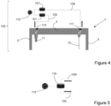
- controllable valves 115, 117 in figure 2 they are situated between the respective reservoirs 101, 107 and the pump 113, in figure 3 they are situated between the respective reservoirs 101, 107 and the liquid handling cover 1, whereas in figure 4 they are integrated into the liquid handling cover 1.
- Figure 5 illustrates yet another variant of the pumping arrangement, with a single recirculation reservoir 119 with three ports, leading respectively to the inlet channel 11, outlet channel 13 and single pump 113. This enables liquid to be recirculated through the microfluidic device 200.
- Figure 6 illustrates a concrete embodiment of a liquid handling cover 1 according to the invention, adapted to interface with a simple microfluidic device 200 comprising a single inlet port 201 and a single outlet port.
- Optical window 7 is simply an opening in the structure, and side supports 5 are constructed as various columns, bosses etc. and may be adapted to be secured to the microfluidic device 200 e.g. by clipping.
- Liquid connections 11a, 13a are simply rigid tubes to which flexible tubing can be attached in known fashion, and internal conduits 11b, 13b are provided such that each liquid connection 11a, 13a is in fluidic communication with its respective channel 11, 13.
- the inlet channel 11 opens higher than the outlet channel 13, so that the former does not enter into contact with liquid in the inlet port 201, whereas the latter does penetrate into the liquid in the outlet port 203 at least when the liquid level is at equilibrium or above, and possibly also below, depending on the length of the outlet channel 13.
- Figure 7 illustrates a variant of the liquid handling cover 1 of figure 6 , which is a cutaway view in order to show the internal conduits 11b, 13b. These are arranged so as to cooperate with inlet and outlet ports 201, 203 which are diagonally opposed to each other on the microfluidic device 200, which has pairs of ports of which only one is used in each case. Naturally, the skilled person understands how to arrange the liquid handling cover 1 so as to use each of the four ports, or any number of ports in any configuration (i.e. separately or connected together, with the possibility of certain ports being unused). It should also be noted that the microfluidic channel 205 comprises a diffusive portion across which liquid diffuses, and reagent or sample ports 207 leading to this diffusive portion.
- the liquid handling cover can be manufactured by additive manufacturing (3D printing) or in two parts fixed together, of any suitable material (such as a biocompatible polymer material).
- Figure 8 shows various configurations of ports 201, 203, and how the inlet channel 11 (in unbroken line) and outlet channel 13 (in dashed line) can be positioned in the ports 201, 203 in function of the shapes thereof, particularly in the case of a conical port with a side recess to prevent overflow (middle drawing) or a conical port with a side recess forming a safe reservoir for aspiration (right-hand drawing).
- Figure 9 illustrates schematically a variant in which liquid handling cover 1 is adapted to service in parallel a plurality of microfluidic devices 200 provided in, or integrated in, a well-plate 209, by means of a plurality of inlet channels 11 and outlet channels 13.
- control unit 121 combines all the reservoirs, valves and pumps, as described above.
Landscapes
- Chemical & Material Sciences (AREA)
- Health & Medical Sciences (AREA)
- Clinical Laboratory Science (AREA)
- Chemical Kinetics & Catalysis (AREA)
- Dispersion Chemistry (AREA)
- Analytical Chemistry (AREA)
- General Health & Medical Sciences (AREA)
- Hematology (AREA)
- Automatic Analysis And Handling Materials Therefor (AREA)
Abstract
Liquid handling cover (1) adapted to be placed over a microfluidic device (200) comprising at least one inlet port (201) and at least one outlet port (203), said liquid handling cover (1) comprising:- a principal portion (3) adapted to be placed above said microfluidic device (200);- at least one inlet channel (11) extending from said principal portion (3) and adapted to face an inlet port (201) of said microfluidic device (200) with a clearance therebetween and adapted to be connected with a source of liquid (101) so as to introduce liquid into said inlet port (201);- at least one outlet channel (13) extending from said principal portion (3) and adapted to enter into an outlet port (203) of said microfluidic device (200) with a clearance therebetween and adapted to be connected with an outlet pump so as to aspirate liquid (L) from said outlet port (203).
Description
- The present invention relates to the field of microfluidic devices. More specifically, it relates to a liquid handling cover for a microfluidic device operating by hydrostatic pressure.
- Microfluidic devices are well-established technologies for chemical, biological, pharmacological, biochemical and other assays, and have in common that a liquid is received from an inlet port and is caused to pass through at least part of the device. The present invention concerns the types of microfluidic devices which have not only an inlet port, but also an outlet port from which liquid is extracted, the liquid flow being caused by a difference in hydrostatic pressure between the inlet and the outlet.
- The concept of using hydrostatic pressure to cause liquid to flow through a microfluidic device is well known, but is however not widespread due to the inherent limitations in terms of control of the pressure and a flow rate that can hence be inconsistent over time. For this reason, many microfluidic platforms requiring continuous flow over several hours, days or weeks tend to use pressure generators, volumetric pumps such as syringes, or pumps that are interfaced with the microfluidic device by means of air and liquid tight sealing.
- For instance, document
EP1724017 discloses a liquid feeding system for a microfluidic device in which an interface is provided which is placed between the device's ports and pipettes, the ports and the pipettes being sealed together. - In the case of flow driven by hydrostatic pressure, this is typically implemented in two different forms in microfluidic devices.
- In a first, static form, the flow is induced by adjusting the inlet and outlet port volumes and/or format, with the device being configured for passive continuous flow through a single channel as liquid moves from the inlet port to the outlet port until equilibrium is reached. Such equilibrium typically takes a matter of a few minutes to be reached, unless liquid is added to the inlet port and removed from the outlet port.
- In a second, dynamic form, a microfluidic device is prefilled with liquid and positioned on a tilting stage, the flow being adjusted via the tilting angle and sometimes also the frequency of variations of the tilting angle. These arrangements generate hydrostatic pressure by positioning one port above the other, and once equilibrium is reached, the angle of tilt can be reversed and the flow occurs in the opposite direction. Examples of such arrangements are given in
WO2017/068376 ,US2020/070165 andWO2021/026373 . - However, such devices are often custom-made for this purpose, and are suboptimal for long-term flow in a single direction.
- The aim of the present invention is hence to at least partially overcome the above-mentioned drawbacks of the prior art.
- More specifically, the invention relates to a liquid handling cover as defined in
claim 1. This liquid handling cover is adapted to be placed over a microfluidic device comprising at least one inlet port and at least one outlet port, said liquid handling cover comprising: - a principal portion adapted to be positioned above said microfluidic device;
- at least one inlet channel extending from said principal portion and adapted to face an inlet port of said microfluidic device with a clearance therebetween (i.e. between the inlet port and the inlet channel, which are hence not sealed to each other) and adapted to be connected with a source of liquid, such as an inlet reservoir associated with a corresponding inlet pump so as to introduce liquid into said inlet port, from where it will enter into the inlet port in the microfluidic device under the effect of gravity and/or contact between liquid in the inlet port and in the inlet channel in the case in which gravity and/or surface tension are not sufficient to break a droplet of liquid. It should be noted that the inlet channel may enter into the inlet port, or may simply open above it;
- at least one outlet channel extending from said principal portion and adapted to enter into an outlet port of said microfluidic device with a clearance therebetween (i.e. between the outlet port and the outlet channel which are hence not sealed to each other) and adapted to be connected with a pump so as to aspirate liquid from said outlet port.
- This arrangement enables continuous unidirectional flow in microfluidic channels of a device without requiring water-tight or air-tight sealing, eliminating all risk of leakage or irregularities typically associated with active flow interfaces. It is compatible with many kinds of microfluidic devices as long as they present at least one inlet port and one outlet port connected by at least one microfluidic channel, and permits them to be operated with continuous flow for relatively long periods (hours, days, weeks, months or even longer). Furthermore, it requires little or no modification to the microfluidic device, which may hence be of a standard type. Further advantages are discussed below.
- Advantageously, each of said inlet channel and said outlet channel are arranged to enter into the corresponding port, i.e. the inlet channel into the inlet port, and the outlet channel into the outlet port, said outlet channel extending further into said outlet port than said inlet channel extends into said inlet port.
- Advantageously, the liquid handling cover may further comprise an optical window, which may be a simple opening or a transparent portion, permitting at least part of said microfluidic device to be seen.
- Advantageously, said liquid handling cover may be adapted to cooperate with said microfluidic device in a manner permitting sterility, for instance with sufficient contact around the edge thereof or even an air and/or liquid tight sealing thereto, although this does not have to be the case and it may have a clearance therewith. This permits the cover to be used for applications requiring sterility, whereas a clearance permits gas exchange with the ambient conditions.
- Advantageously, at least one liquid reservoir may be provided on a surface of said principal portion facing away from said microfluidic device, enabling liquid to be placed therein to increase the humidity proximate to the microfluidic device, to minimize evaporation of liquid therefrom.
- Advantageously, the liquid handling cover may comprise an array of said inlet channels and said outlet channels adapted to cooperate with a plurality of said microfluidic devices such that they can be operated in parallel or sequentially.
- The liquid handling cover of the invention can be incorporated into a liquid handling system for a microfluidic device, which further comprises at least one pump adapted to cause liquid to move from a reservoir to said inlet channel and to cause liquid to be aspirated from said outlet port via said outlet channel.
- In one variant, the at least one pump comprises:
- an inlet pump adapted to cause liquid to be moved from an inlet reservoir to said inlet channel, and;
- an outlet pump adapted to cause liquid to be moved from said outlet channel into an outlet reservoir.
- In a different variant, the at least one pump is a single pump adapted to cause liquid to be moved from an inlet reservoir to said inlet channel, and to cause liquid to be moved from said outlet channel into an outlet reservoir, a controllable valve being associated with each reservoir.
- These controllable valves may be arranged either:
- between said reservoirs and said pump;
- between said reservoirs and said liquid handling cover; or
- integrated into said liquid handling cover.
- In a yet different variant, said at least one pump is a single pump and said reservoir is a recirculation reservoir adapted to receive liquid from said outlet channel and to provide liquid to said inlet channel, enabling a sample to be circulated continuously.
- Further details of the invention will become apparent upon reading the detailed description below, in reference to the appended drawings in which:
-
Figure 1 is a schematic view of a liquid handling system incorporating a liquid handling cover according to the invention, together with a microfluidic device; -
Figures 2-5 are schematic views of various pumping arrangements which can be utilized with a liquid handling system; -
Figures 6 and 7 are views of concrete embodiments of liquid handling covers according to the invention and the types of microfluidic devices they are adapted to be used with; -
Figure 8 is three schematic views of the relationship between the inlet and outlet channels and different forms of ports in the microfluidic device; and -
Figure 9 is a schematic view of an adaptation of the invention to multiple microfluidic devices. -
Figure 1 illustrates a first embodiment of aliquid handling cover 1 according to the invention, together with other components of aliquid handling system 100 and amicrofluidic device 200 with which theliquid handling cover 1 is intended to cooperate. -
Liquid handling cover 1 comprises aprincipal portion 3 intended to be positioned above and facing saidmicrofluidic device 200, and optionallateral supports 5 to support it. The exact shape of theprincipal portion 3 and optionallateral supports 5 can be adapted according to need, based on the dimensions of themicrofluidic device 200, whether thecover 1 is intended to serve a single or multiplemicrofluidic devices 200, whether these are provided in a well plate or other support, and so on. Typically, theprincipal portion 3 is arranged substantially parallel to the microfluidic device, but this does not strictly need to be the case. - Further optional features of the
principal portion 3 of theliquid handling cover 1 are anoptical window 7 arranged so as to allow an operator to see at least part of themicrofluidic device 200, for instance to be able to visualize a sample or a colour changing element of this latter, and so on. Thisoptical window 7 can either be simply an opening, or may be constituted by a piece of transparent material such as glass or a transparent polymer. Furthermore, a liquid reservoir 9 can be provided on an upper surface of theprincipal portion 3, in order to contribute to maintaining a humid environment in the proximity of thecover 1, so as to help reduce evaporation in themicrofluidic device 200. -
Cover 1 further comprises aninlet channel 11 extending from an inletliquid connector 11 a in theprincipal portion 3 in the direction of themicrofluidic device 200, namely towards aninlet port 201 that serves as an inlet reservoir, and anoutlet channel 13, which extends from an outletliquid connector 13asecond port 13a such that the distal extremity ofoutlet channel 13 is positioned down within anoutlet port 203 serving as an outlet reservoir. It should be noted that a clearance is present between each of thechannels respective ports channels ports inlet channel 11 may be situated completely above theinlet port 201, or may extend into this latter, according to the needs of the constructor. - The
inlet channel 11 is adapted to be in fluidic communication with a source ofliquid 101, here illustrated as aninlet reservoir 101 associated with aninlet pump 103 adapted to cause liquid L to flow from theinlet reservoir 101 to theinlet channel 11 via asuitable inlet conduit 105, interfacing with the inlet channel via the inletliquid connector 11a. Likewise, theoutlet channel 13 is adapted to be in fluidic communication with anoutlet reservoir 107, and liquid is aspirated from theoutlet channel 13, though anoutlet conduit 109 into thisreservoir 107 by anoutlet pump 111, thisoutlet conduit 109 interfacing with theoutlet channel 13 via an outletliquid connector 13a.Pumps inlet pump 103 may be replaced by the force of gravity, by simply arranginginlet reservoir 101 higher than thecover 1. - From the foregoing, it is clear that the
cover 1 and the arrangements for handling liquid, namely thereservoirs conduits - By aspirating liquid L from the
outlet port 203 via the outlet channel, and introducing liquid L into the inlet port 201 (which may require contact between the liquid in theinlet port 201 and liquid at the tip of theinlet channel 11 under certain circumstances), a height difference h between the level of liquid in the twoports inlet port 201 to theoutlet port 203 along amicrofluidic channel 205, and through any functional elements of themicrofluidic device 200. The type of microfluidic device is not important for the present invention, and need not be discussed at length, but microfluidic devices for chemical, biochemical, pharmaceutical and biological assays can be used, insofar as they have both at least oneinlet port 201 and at least oneoutlet port 203. - The
system 100 may be operated either continuously, or by alternately aspirating and injecting liquid L, the liquid flow through themicrofluidic device 200. - It should be noted that it is possible to both seal the
liquid handling cover 1 to themicrofluidic device 200 by suitable seals or flexible materials incorporated into the design of thecover 1 and/or themicrofluidic device 200, this sealing typically being around the edge of themicrofluidic device 200, but it can also simply be left unsealed with a clearance between thecover 1 and themicrofluidic device 200 and hence open to the environment, or simply with sufficient contact to between theliquid handling cover 1 and themicrofluidic device 200 to assure sterility. - One particularly advantageous way to operate the
system 100 is as follows. Firstly, amicrofluidic device 200 which is prefilled with liquid L to a certain height is provided and thecover 1 is placed above it with theinlet channel 11 andoutlet channel 13 correctly positioned as described above. Alternatively, thedevice 200 may be dry when positioned and then filled by introducing a predetermined quantity of liquid L via theinlet channel 11, the liquid levels being then allowed to reach equilibrium or a small positive value. - Subsequently, liquid L is aspirated from the
outlet port 203 via theoutlet channel 13 under the effect of theoutlet pump 111, typically for a few seconds, which may be to the point where the liquid level drops below the level of the extremity of theoutlet channel 13 such that air is aspirated (which can be detected by an appropriate sensor). - Subsequently,
inlet pump 103 causes liquid L to flow from theinlet reservoir 101 into theinlet port 201 via theinlet channel 11, typically for a few seconds. This can be metered and, for instance, correspond substantially to the quantity of liquid aspirated from theoutlet port 203 in the previous step. - The
system 100 is then paused, and liquid is allowed to flow for e.g. several minutes along themicrofluidic channel 205. - The steps of aspiration, introduction and pausing are then repeated as required, guaranteeing a continuous and unidirectional flow.
- Of course, other methodologies are possible, such as introducing drops of liquid into the
inlet port 201 at the same rate that liquid is aspirated from theoutlet port 203. -
Figures 2, 3 and4 illustrate variants of a pumping arrangement with a singlebidirectional pump 113.Controllable valves inlet valve 115 andclosing outlet valve 117, thesingle pump 113 can cause liquid to flow from theinlet reservoir 101 to theinlet channel 11, and by openingoutlet valve 117 and closinginlet valve 115, thesingle pump 113 can cause liquid to be aspirated via theoutlet channel 13 into theoutlet reservoir 107. The difference between the 3 arrangements is simply the location of thecontrollable valves 115, 117: infigure 2 they are situated between therespective reservoirs pump 113, infigure 3 they are situated between therespective reservoirs liquid handling cover 1, whereas infigure 4 they are integrated into theliquid handling cover 1. -
Figure 5 illustrates yet another variant of the pumping arrangement, with asingle recirculation reservoir 119 with three ports, leading respectively to theinlet channel 11,outlet channel 13 andsingle pump 113. This enables liquid to be recirculated through themicrofluidic device 200. -
Figure 6 illustrates a concrete embodiment of aliquid handling cover 1 according to the invention, adapted to interface with a simplemicrofluidic device 200 comprising asingle inlet port 201 and a single outlet port.Optical window 7 is simply an opening in the structure, and side supports 5 are constructed as various columns, bosses etc. and may be adapted to be secured to themicrofluidic device 200 e.g. by clipping.Liquid connections internal conduits liquid connection respective channel - As can be clearly seen, the
inlet channel 11 opens higher than theoutlet channel 13, so that the former does not enter into contact with liquid in theinlet port 201, whereas the latter does penetrate into the liquid in theoutlet port 203 at least when the liquid level is at equilibrium or above, and possibly also below, depending on the length of theoutlet channel 13. -
Figure 7 illustrates a variant of theliquid handling cover 1 offigure 6 , which is a cutaway view in order to show theinternal conduits outlet ports microfluidic device 200, which has pairs of ports of which only one is used in each case. Naturally, the skilled person understands how to arrange theliquid handling cover 1 so as to use each of the four ports, or any number of ports in any configuration (i.e. separately or connected together, with the possibility of certain ports being unused). It should also be noted that themicrofluidic channel 205 comprises a diffusive portion across which liquid diffuses, and reagent orsample ports 207 leading to this diffusive portion. - In each of
figures 6 and 7 , the liquid handling cover can be manufactured by additive manufacturing (3D printing) or in two parts fixed together, of any suitable material (such as a biocompatible polymer material). -
Figure 8 shows various configurations ofports ports -
Figure 9 illustrates schematically a variant in whichliquid handling cover 1 is adapted to service in parallel a plurality ofmicrofluidic devices 200 provided in, or integrated in, a well-plate 209, by means of a plurality ofinlet channels 11 andoutlet channels 13. In this case,control unit 121 combines all the reservoirs, valves and pumps, as described above. - In view of the foregoing, it can be seen that the invention presents the following advantages.
- a) The
liquid handling cover 1 of the invention enables continuous unidirectional flow in microfluidic channels of a device without requiring water-tight or air-tight sealing. Therefore, all risk of leakage or irregularities typically associated with active flow interfaces can be disregarded. Furthermore, unidirectional flow is a significant advantage compared to existing non-sealed methods such as tilting, since the liquid only makes a single pass through the microfluidic chip. - b) The
liquid handling cover 1 of the invention is compatible with all kinds ofmicrofluidic devices 200 as long as they present at least oneinlet port 201 and oneoutlet port 203 connected by at least onemicrofluidic channel 205, and permits them to be operated with continuous flow. As a result, it is not limited to any particularmicrofluidic device 200 design, so long as it has these characteristics. - c) The
liquid handling cover 1 of the invention permits long-term continuous unidirectional flow, with little or no modification of themicrofluidic device 200 itself or use of a tilting apparatus. In a static configuration, theliquid handling cover 1 of the invention avoids the implementation of large volume reservoirs on themicrofluidic device 200 inlet andoutlet ports microfluidic device 200. - d) In the case in which an
optical window 7 is provided, observation of the microfluidic channel in a (semi-)transparentmicrofluidic device 200 is possible, and in the case in which light passage through themicrofluidic device 200 is desired, the presence of theoptical window 7 permits this. - e) In the case in which a liquid reservoir 9 is provided, evaporation of liquid from the
microfluidic device 200 can be minimized, which can be useful for long term experiments, by means of an easily accessible liquid reservoir 9 located on its top, providing a humid surrounding at the chip inlet andoutlet ports - f) In the case in which the
liquid handling cover 1 cooperates with themicrofluidic device 200 in a sterile fashion (whether fully sealed or simply with sufficient contact), this can provide a contained environment around the chip, guaranteeing sterility of the sample in the chip while enabling gas exchange. - g) The
liquid handling cover 1 of the invention is up-scalable as shown infigure 9 , to enable unidirectional flow to be maintained in multiplemicrofluidic devices 200, or in or amicrofluidic device 200 configured as an array or multi-well-plate containing multiple microfluidic ports and channels integrated therein, simultaneously or sequentially, by means of a specific configuration of the pumping system and valves. In this manner, the invention enables parallelization and multiplexing of microfluidic experiments. - h) The
liquid handling cover 1 of the invention is furthermore compatible with unidirectional recirculation of the sample through the channel, as illustrated infigure 5 , without requiring customization of the design of themicrofluidic device 200. - Although the invention has been described in terms of specific embodiments, variations thereto are possible without departing from the scope of the appended claims.
Claims (12)
- Liquid handling cover (1) adapted to be placed over a microfluidic device (200) comprising at least one inlet port (201) and at least one outlet port (203), said liquid handling cover (1) comprising:- a principal portion (3) adapted to be positioned above said microfluidic device (200);- at least one inlet channel (11) extending from said principal portion (3) and adapted to face an inlet port (201) of said microfluidic device (200) with a clearance therebetween and adapted to be connected with a source of liquid (101) so as to introduce liquid into said inlet port (201);- at least one outlet channel (13) extending from said principal portion (3) and adapted to enter into an outlet port (203) of said microfluidic device (200) with a clearance therebetween and adapted to be connected with a pump so as to aspirate liquid (L) from said outlet port (203).
- Liquid handling cover (1) according to claim 1, wherein each of said inlet channel (11) and said outlet channel (13) are arranged to enter into the corresponding port (201, 203), said outlet channel (13) extending further into said outlet port (203) than said inlet channel (11) extends into said inlet port (201).
- Liquid handling cover (1) according to any preceding claim, further comprising an optical window (7) adapted to permit at least part of said microfluidic device (200) to be seen.
- Liquid handling cover (1) according to any preceding claim, wherein said liquid handling cover (1) is adapted to cooperate with said microfluidic device (200) in a manner permitting sterility.
- Liquid handling cover (1) according to any of claims 1-3, wherein said liquid handling cover (1) is adapted to have a clearance with said microfluidic device (200).
- Liquid handling cover (1) according to any preceding claim, further comprising at least one liquid reservoir (9) provided on a surface of said principal portion (3) facing away from said microfluidic device (200).
- Liquid handling cover (1) according to any preceding claim, comprising an array of said inlet channels (11) and said outlet channels (13) adapted to cooperate with a plurality of said microfluidic devices (200).
- Liquid handling system (100) for a microfluidic device, comprising:- a liquid handling cover (1) according to any preceding claim;- at least one pump (103, 111; 113) adapted to cause liquid (L) to move from a reservoir (101, 107; 119) to said inlet channel (11) and to cause liquid (L) to be aspirated from said outlet port (203) via said outlet channel (13).
- Liquid handling system (100) according to claim 8, wherein said at least one pump comprises:- an inlet pump (103) adapted to cause liquid to be moved from an inlet reservoir (101) to said inlet channel (11), and;- an outlet pump (111) adapted to cause liquid (L) to be moved from said outlet channel (13) into an outlet reservoir (107).
- Liquid handling system (100) according to claim 8, wherein said at least one pump is a single pump (113) adapted to cause liquid to be moved from an inlet reservoir (101) to said inlet channel (11), and to cause liquid to be moved from said outlet channel (13) into an outlet reservoir (107), a controllable valve (115, 117) being associated with each reservoir (101, 107).
- Liquid handling system (100) according to claim 10, wherein said controllable valves (115, 117) are arranged either:- between said respective reservoirs (101, 107) and said pump (113);- between said respective reservoirs (101, 107) and said liquid handling cover (1); or- integrated into said liquid handling cover (1).
- Liquid handling system (100) according to claim 8, wherein said at least one pump is a single pump (113) and said reservoir is a recirculation reservoir (119) adapted to receive liquid from said outlet channel (13) and to provide liquid to said inlet channel (11).
Priority Applications (1)
| Application Number | Priority Date | Filing Date | Title |
|---|---|---|---|
| EP23162537.7A EP4431185A1 (en) | 2023-03-17 | 2023-03-17 | Liquid handling cover for a microfluidic device |
Applications Claiming Priority (1)
| Application Number | Priority Date | Filing Date | Title |
|---|---|---|---|
| EP23162537.7A EP4431185A1 (en) | 2023-03-17 | 2023-03-17 | Liquid handling cover for a microfluidic device |
Publications (1)
| Publication Number | Publication Date |
|---|---|
| EP4431185A1 true EP4431185A1 (en) | 2024-09-18 |
Family
ID=85703934
Family Applications (1)
| Application Number | Title | Priority Date | Filing Date |
|---|---|---|---|
| EP23162537.7A Pending EP4431185A1 (en) | 2023-03-17 | 2023-03-17 | Liquid handling cover for a microfluidic device |
Country Status (1)
| Country | Link |
|---|---|
| EP (1) | EP4431185A1 (en) |
Citations (6)
| Publication number | Priority date | Publication date | Assignee | Title |
|---|---|---|---|---|
| EP1724017A2 (en) | 2005-05-19 | 2006-11-22 | Fuji Photo Film Co., Ltd. | Fluid feeding system, fluid feeding method and flow channel unit |
| US20140080226A1 (en) * | 2012-09-19 | 2014-03-20 | Bio-Rad Laboratories, Inc. | Fluid transport system with gasket |
| US20140378348A1 (en) * | 2013-06-21 | 2014-12-25 | Bio-Rad Laboratories, Inc. | Microfluidic system with fluid pickups |
| WO2017068376A1 (en) | 2015-10-22 | 2017-04-27 | University Of Newcastle Upon Tyne | Cell culture |
| US20200070165A1 (en) | 2018-06-14 | 2020-03-05 | Cornell University | Recirculating unidirectional perfusion flow devices and methods of use thereof |
| WO2021026373A1 (en) | 2019-08-06 | 2021-02-11 | Hackensack Meridian Health Center For Discovery and Innovation | Pumpless platform for high-throughput dynamic multicellular culture and chemosensitivity evaluation |
-
2023
- 2023-03-17 EP EP23162537.7A patent/EP4431185A1/en active Pending
Patent Citations (6)
| Publication number | Priority date | Publication date | Assignee | Title |
|---|---|---|---|---|
| EP1724017A2 (en) | 2005-05-19 | 2006-11-22 | Fuji Photo Film Co., Ltd. | Fluid feeding system, fluid feeding method and flow channel unit |
| US20140080226A1 (en) * | 2012-09-19 | 2014-03-20 | Bio-Rad Laboratories, Inc. | Fluid transport system with gasket |
| US20140378348A1 (en) * | 2013-06-21 | 2014-12-25 | Bio-Rad Laboratories, Inc. | Microfluidic system with fluid pickups |
| WO2017068376A1 (en) | 2015-10-22 | 2017-04-27 | University Of Newcastle Upon Tyne | Cell culture |
| US20200070165A1 (en) | 2018-06-14 | 2020-03-05 | Cornell University | Recirculating unidirectional perfusion flow devices and methods of use thereof |
| WO2021026373A1 (en) | 2019-08-06 | 2021-02-11 | Hackensack Meridian Health Center For Discovery and Innovation | Pumpless platform for high-throughput dynamic multicellular culture and chemosensitivity evaluation |
Similar Documents
| Publication | Publication Date | Title |
|---|---|---|
| JP5152198B2 (en) | Dispensing device | |
| JP4858580B2 (en) | Reaction processing method using reaction vessel plate | |
| US11135582B2 (en) | Cartridge systems, capacitive pumps and multi-throw valves and pump-valve systems and applications of same | |
| US20090029422A1 (en) | Reactor plate and reaction processing method | |
| US8580575B2 (en) | Reactor plate and reaction processing method | |
| US7938573B2 (en) | Cartridge having variable volume reservoirs | |
| WO2016064757A1 (en) | Modular microfluidic system for perfused cell culture | |
| CN112423884A (en) | Fluid system for receiving, discharging and moving a fluid, method of treating a fluid in a fluid system | |
| US20110226339A1 (en) | Microchip and liquid sending method for microchip | |
| US11207685B2 (en) | System, method, and device for forming an array of emulsions | |
| US20100062446A1 (en) | Reactor plate and reaction processing method | |
| US20250033041A1 (en) | Reagent pre-embedding and sample injecting device, and sample injection method therefor and application thereof | |
| US20220241786A1 (en) | Centrifugal Microfluidic Chip, Kit and System for On-Chip Gas Supply | |
| US11465144B2 (en) | Cartridge systems, capacitive pumps and multi-throw valves and pump-valve systems and applications of same | |
| JP2009543055A (en) | Fluid handling system for flow-through assays | |
| JP4872923B2 (en) | Reaction vessel | |
| CN101183102A (en) | Micro total analysis chip and micro total analysis system | |
| JP4962227B2 (en) | Reaction vessel plate and reaction processing method using the reaction vessel plate | |
| JP4872922B2 (en) | Reaction vessel | |
| US11745178B2 (en) | Fluid processing cassettes incorporating micro- and macrofluidic channels | |
| KR20230149808A (en) | Chemical processing systems, instruments and sample cartridges | |
| JP4962575B2 (en) | Reaction vessel | |
| NL2034536B1 (en) | Method and apparatus for cultivating at least one cell in a cell culture plate | |
| JP4872921B2 (en) | Reaction vessel | |
| JP2023054876A (en) | Micro passage device |
Legal Events
| Date | Code | Title | Description |
|---|---|---|---|
| PUAI | Public reference made under article 153(3) epc to a published international application that has entered the european phase |
Free format text: ORIGINAL CODE: 0009012 |
|
| STAA | Information on the status of an ep patent application or granted ep patent |
Free format text: STATUS: THE APPLICATION HAS BEEN PUBLISHED |
|
| AK | Designated contracting states |
Kind code of ref document: A1 Designated state(s): AL AT BE BG CH CY CZ DE DK EE ES FI FR GB GR HR HU IE IS IT LI LT LU LV MC ME MK MT NL NO PL PT RO RS SE SI SK SM TR |
|
| STAA | Information on the status of an ep patent application or granted ep patent |
Free format text: STATUS: REQUEST FOR EXAMINATION WAS MADE |
|
| 17P | Request for examination filed |
Effective date: 20250318 |