EP4430644B1 - Transformer system for a direct current converter system - Google Patents
Transformer system for a direct current converter system Download PDFInfo
- Publication number
- EP4430644B1 EP4430644B1 EP22757892.9A EP22757892A EP4430644B1 EP 4430644 B1 EP4430644 B1 EP 4430644B1 EP 22757892 A EP22757892 A EP 22757892A EP 4430644 B1 EP4430644 B1 EP 4430644B1
- Authority
- EP
- European Patent Office
- Prior art keywords
- transformer
- winding
- windings
- converter
- phase
- Prior art date
- Legal status (The legal status is an assumption and is not a legal conclusion. Google has not performed a legal analysis and makes no representation as to the accuracy of the status listed.)
- Active
Links
Images

Classifications
-
- H—ELECTRICITY
- H01—ELECTRIC ELEMENTS
- H01F—MAGNETS; INDUCTANCES; TRANSFORMERS; SELECTION OF MATERIALS FOR THEIR MAGNETIC PROPERTIES
- H01F30/00—Fixed transformers not covered by group H01F19/00
- H01F30/06—Fixed transformers not covered by group H01F19/00 characterised by the structure
- H01F30/12—Two-phase, three-phase or polyphase transformers
-
- H—ELECTRICITY
- H01—ELECTRIC ELEMENTS
- H01F—MAGNETS; INDUCTANCES; TRANSFORMERS; SELECTION OF MATERIALS FOR THEIR MAGNETIC PROPERTIES
- H01F30/00—Fixed transformers not covered by group H01F19/00
- H01F30/06—Fixed transformers not covered by group H01F19/00 characterised by the structure
- H01F30/10—Single-phase transformers
-
- H—ELECTRICITY
- H02—GENERATION; CONVERSION OR DISTRIBUTION OF ELECTRIC POWER
- H02J—ELECTRIC POWER NETWORKS; CIRCUIT ARRANGEMENTS OR SYSTEMS FOR SUPPLYING OR DISTRIBUTING ELECTRIC POWER; SYSTEMS FOR STORING ELECTRIC ENERGY
- H02J3/00—Circuit arrangements for AC mains or AC distribution networks
- H02J3/36—Arrangements for transfer of electric power between AC networks via high-voltage DC [HVDC] links; Arrangements for transfer of electric power between generators and networks via HVDC links
-
- H—ELECTRICITY
- H02—GENERATION; CONVERSION OR DISTRIBUTION OF ELECTRIC POWER
- H02M—APPARATUS FOR CONVERSION BETWEEN AC AND AC, BETWEEN AC AND DC, OR BETWEEN DC AND DC, AND FOR USE WITH MAINS OR SIMILAR POWER SUPPLY SYSTEMS; CONVERSION OF DC OR AC INPUT POWER INTO SURGE OUTPUT POWER; CONTROL OR REGULATION THEREOF
- H02M1/00—Details of apparatus for conversion
- H02M1/0067—Converter structures employing plural converter units, other than for parallel operation of the units on a single load
- H02M1/0077—Plural converter units whose outputs are connected in series
-
- H—ELECTRICITY
- H02—GENERATION; CONVERSION OR DISTRIBUTION OF ELECTRIC POWER
- H02M—APPARATUS FOR CONVERSION BETWEEN AC AND AC, BETWEEN AC AND DC, OR BETWEEN DC AND DC, AND FOR USE WITH MAINS OR SIMILAR POWER SUPPLY SYSTEMS; CONVERSION OF DC OR AC INPUT POWER INTO SURGE OUTPUT POWER; CONTROL OR REGULATION THEREOF
- H02M1/00—Details of apparatus for conversion
- H02M1/12—Arrangements for reducing harmonics from AC input or output
-
- H—ELECTRICITY
- H02—GENERATION; CONVERSION OR DISTRIBUTION OF ELECTRIC POWER
- H02M—APPARATUS FOR CONVERSION BETWEEN AC AND AC, BETWEEN AC AND DC, OR BETWEEN DC AND DC, AND FOR USE WITH MAINS OR SIMILAR POWER SUPPLY SYSTEMS; CONVERSION OF DC OR AC INPUT POWER INTO SURGE OUTPUT POWER; CONTROL OR REGULATION THEREOF
- H02M5/00—Conversion of AC power input into AC power output, e.g. for change of voltage, for change of frequency, for change of number of phases
- H02M5/02—Conversion of AC power input into AC power output, e.g. for change of voltage, for change of frequency, for change of number of phases without intermediate conversion into DC
- H02M5/04—Conversion of AC power input into AC power output, e.g. for change of voltage, for change of frequency, for change of number of phases without intermediate conversion into DC by static converters
- H02M5/10—Conversion of AC power input into AC power output, e.g. for change of voltage, for change of frequency, for change of number of phases without intermediate conversion into DC by static converters using transformers
- H02M5/12—Conversion of AC power input into AC power output, e.g. for change of voltage, for change of frequency, for change of number of phases without intermediate conversion into DC by static converters using transformers for conversion of voltage or current amplitude only
-
- H—ELECTRICITY
- H02—GENERATION; CONVERSION OR DISTRIBUTION OF ELECTRIC POWER
- H02M—APPARATUS FOR CONVERSION BETWEEN AC AND AC, BETWEEN AC AND DC, OR BETWEEN DC AND DC, AND FOR USE WITH MAINS OR SIMILAR POWER SUPPLY SYSTEMS; CONVERSION OF DC OR AC INPUT POWER INTO SURGE OUTPUT POWER; CONTROL OR REGULATION THEREOF
- H02M7/00—Conversion of AC power input into DC power output; Conversion of DC power input into AC power output
- H02M7/003—Constructional details, e.g. physical layout, assembly, wiring or busbar connections
-
- H—ELECTRICITY
- H02—GENERATION; CONVERSION OR DISTRIBUTION OF ELECTRIC POWER
- H02M—APPARATUS FOR CONVERSION BETWEEN AC AND AC, BETWEEN AC AND DC, OR BETWEEN DC AND DC, AND FOR USE WITH MAINS OR SIMILAR POWER SUPPLY SYSTEMS; CONVERSION OF DC OR AC INPUT POWER INTO SURGE OUTPUT POWER; CONTROL OR REGULATION THEREOF
- H02M7/00—Conversion of AC power input into DC power output; Conversion of DC power input into AC power output
- H02M7/42—Conversion of DC power input into AC power output without possibility of reversal
- H02M7/44—Conversion of DC power input into AC power output without possibility of reversal by static converters
- H02M7/48—Conversion of DC power input into AC power output without possibility of reversal by static converters using discharge tubes with control electrode or semiconductor devices with control electrode
- H02M7/493—Conversion of DC power input into AC power output without possibility of reversal by static converters using discharge tubes with control electrode or semiconductor devices with control electrode the static converters being arranged for operation in parallel
-
- H—ELECTRICITY
- H01—ELECTRIC ELEMENTS
- H01F—MAGNETS; INDUCTANCES; TRANSFORMERS; SELECTION OF MATERIALS FOR THEIR MAGNETIC PROPERTIES
- H01F38/00—Adaptations of transformers or inductances for specific applications or functions
- H01F2038/006—Adaptations of transformers or inductances for specific applications or functions matrix transformer consisting of several interconnected individual transformers working as a whole
-
- H—ELECTRICITY
- H01—ELECTRIC ELEMENTS
- H01F—MAGNETS; INDUCTANCES; TRANSFORMERS; SELECTION OF MATERIALS FOR THEIR MAGNETIC PROPERTIES
- H01F27/00—Details of transformers or inductances, in general
- H01F27/02—Casings
-
- H—ELECTRICITY
- H01—ELECTRIC ELEMENTS
- H01F—MAGNETS; INDUCTANCES; TRANSFORMERS; SELECTION OF MATERIALS FOR THEIR MAGNETIC PROPERTIES
- H01F27/00—Details of transformers or inductances, in general
- H01F27/28—Coils; Windings; Conductive connections
-
- H—ELECTRICITY
- H02—GENERATION; CONVERSION OR DISTRIBUTION OF ELECTRIC POWER
- H02J—ELECTRIC POWER NETWORKS; CIRCUIT ARRANGEMENTS OR SYSTEMS FOR SUPPLYING OR DISTRIBUTING ELECTRIC POWER; SYSTEMS FOR STORING ELECTRIC ENERGY
- H02J3/00—Circuit arrangements for AC mains or AC distribution networks
- H02J3/38—Arrangements for feeding a single network from two or more generators or sources in parallel; Arrangements for feeding already energised networks from additional generators or sources in parallel
-
- Y—GENERAL TAGGING OF NEW TECHNOLOGICAL DEVELOPMENTS; GENERAL TAGGING OF CROSS-SECTIONAL TECHNOLOGIES SPANNING OVER SEVERAL SECTIONS OF THE IPC; TECHNICAL SUBJECTS COVERED BY FORMER USPC CROSS-REFERENCE ART COLLECTIONS [XRACs] AND DIGESTS
- Y02—TECHNOLOGIES OR APPLICATIONS FOR MITIGATION OR ADAPTATION AGAINST CLIMATE CHANGE
- Y02E—REDUCTION OF GREENHOUSE GAS [GHG] EMISSIONS, RELATED TO ENERGY GENERATION, TRANSMISSION OR DISTRIBUTION
- Y02E60/00—Enabling technologies; Technologies with a potential or indirect contribution to GHG emissions mitigation
- Y02E60/60—Arrangements for transfer of electric power between AC networks or generators via a high voltage DC link [HVCD]
Definitions
- the present disclosure relates to a transformer system for a direct current (DC) converter system.
- the converter system may be suitable for high voltage direct current (HVDC) or Ultra High Voltage Direct Current (UHVDC) power transmission, for example.
- HVDC high voltage direct current
- UHVDC Ultra High Voltage Direct Current
- CN 216672848 U discloses a converter system for direct current power transmission.
- the converter system comprises converter transformers connected to line commuted converters (LLC).
- LLC line commuted converters
- Two of the transformers comprises two sets of secondary windings which are connected to produce a secondary voltage having a phase-shift to the primary voltage by -15° and 15°, respectively.
- the secondary windings may be connected in an extended-side delta connection, for example.
- the primary windings may be connected in a wye or delta configuration, for example.
- EP 0 471 183 A2 discloses a transformer circuit providing a phase shift of 15 °.
- EP 3 232 452 A1 discloses a phase-shift transformer comprising three single-phase transformers, wherein each of the single-phase transformers comprises a series transformer and an excitation transformer that are arranged in the same oil tank and are two devices independent of each other.
- DE 10 2016 216949 A1 discloses a system of three single-phase transformers located in separate tanks, wherein valve windings are connected in a star connection.
- At least some embodiments of the disclosure relate to an improved transformer system for a direct current converter system.
- the transformer system may be easier to transport to and/or install at an installation site.
- a transformer system for a direct current converter system comprises a plurality of windings for three electrical phases, the windings being electrically connected to provide a 15° phase shift, and comprising at least three separate tanks, wherein the windings associated to different electrical phases are located in different ones of the separate tanks.
- the 15° phase shift may be a phase shift by +15° or -15°.
- Each of the separate transformer sub-parts as defined by the separate tanks can be also denoted as a transformer unit.
- the transformer system may be defined as comprising three or more single-phase units, interconnected to each other to form the transformer system.
- the three or more single-phase units form a three-phase transformer.
- Each of the transformer units comprises primary and secondary windings, attributed to primary side and the secondary side, which may be the line-side and the valve-side, respectively.
- the transformer system comprises for each electrical phase a first winding and a second winding, the windings of all electrical phases connected in an extended-side delta configuration.
- the first winding and the second winding may be secondary-side windings.
- For each electrical phase exactly one first winding and exactly one second winding may be provided. It is also possible that more than one first winding and more than two second windings are provided, depending on the power requirements per winding.
- the transformer may further comprise for each electrical phase at least one winding for the primary side, in particular the line-side.
- the first winding and second winding are located on a common core.
- the first winding and the second winding may be located on separate limbs on the common core.
- the separate limbs may be arranged parallel to each other.
- Line-side windings may be located on the same limbs as the first and second windings
- the first winding and the second winding for the same electrical phase are located in the same tank.
- the transformer system may comprise exactly one tank for each electrical phase.
- An electrical connection between the first winding and the second winding can be provided inside the tank. Accordingly, a lead-through connection is not required for forming the inter-connection between the first and second winding.
- the first winding and the second winding for the same electrical phase can be located in different tanks.
- the transformer system may comprise exactly two tanks for each electrical phase.
- the transformer system may comprise for each electrical phase exactly three lead-through connections for one of the transformer sides, in particular for the valve-side. This may be the case when the transformer system is formed by exactly three transformer units, i.e. one unit for each phase. Further lead-through connections may be provided for the line-side.
- the transformer system may comprise more than three lead-through connections for the valve-side.
- two lead-through connections may be required for the valve-side for each tank. In total, twelve lead-through connections are required for the valve-side.
- a direct current converter system comprises at least one transformer system as described in the foregoing.
- the transformer system may comprise two of the transformer systems. A first one of the transformer systems may provide a 15° phase shift and the second one of the transformer systems may provide a -15° phase shift.
- the converter system for direct current transmission comprises a first converter unit comprising at least one converter transformer comprising a first two sets of secondary windings; and a first line commutated converter (LCC) and a second LCC connected in series on a DC side, wherein the first LCC and the second LCC are coupled with respective sets of secondary windings in the first two sets of secondary windings in an extended-delta connection, respectively, to shift voltages of the first two sets of secondary windings by a phase angle of +15° and -15°, respectively.
- the at least one converter transformer may be formed by the transformer system as described in the foregoing.
- the converter system may further comprise a second convertor unit connected in series with the first converter unit on the DC side, wherein the second converter unit comprises at least one converter transformer comprising a second two sets of secondary windings; and a third LCC and a fourth LCC connected in series on the DC side, wherein the third LCC is coupled with one of the second two sets of secondary windings in a wye connection, and the fourth LCC is coupled with another one of the second two sets of secondary windings in a delta connection.
- a second convertor unit connected in series with the first converter unit on the DC side, wherein the second converter unit comprises at least one converter transformer comprising a second two sets of secondary windings; and a third LCC and a fourth LCC connected in series on the DC side, wherein the third LCC is coupled with one of the second two sets of secondary windings in a wye connection, and the fourth LCC is coupled with another one of the second two sets of secondary windings in a delta connection.
- the first converter unit may comprise two converter transformers, each converter transformer comprising a corresponding set of secondary windings in the first two sets of secondary windings, wherein the first LCC is coupled with one set of secondary windings in the first two sets of secondary windings in an extended-delta connection to shift the voltage of the set of secondary windings by a phase angle of +15°, and the second LCC is coupled with another set of secondary windings in the first two sets of secondary windings in an extended-delta connection to shift the voltage of the set of secondary windings by a phase angle of -15°.
- Each of or only one of the two converter transformers may be formed by a transformer system as described in the foregoing.
- the present disclosure comprises several aspects and embodiments. Every feature described with respect to one of the aspects and embodiments is also disclosed herein with respect to the other aspects and embodiments, even if the respective feature is not explicitly mentioned in this context.
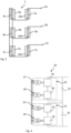
- Figure 1 shows a transformer system 1 suitable for a direct current LCC converter.
- the transformer system 1 provides a 15° phase shift and is, thus suitable, for 24 pulse operation, for example.
- the transformer system 1 comprises three transformer units 2a, 2b, 2c being connected to different electrical phases 3a, 3b, 3c. In this figure, only a secondary side of the transformer system 1 is shown, wherein the secondary side is the valve side 4.
- a primary side of the transformer system 1 is a line side and may comprise windings connected in a wye or delta configuration, for example.
- Each of the transformer units 2a, 2b, 2c comprises a first winding 4a, 4b, 4c and a second winding 5a, 5b, 5c.
- the first windings 4a, 4b, 4c are connected to each other in a delta configuration.
- the second windings 5a, 5b, 5c are also known as extended windings and are connected between the associated first winding 5a, 5b, 5c and the phases 3a, 3b, 3c.
- the connection is known as an extended-side delta connection.
- the three transformer units 2a, 2b, 2c are defined by the location of the windings 4a-4c, 5a-5c in separate tanks 6a, 6b, 6c.
- Each of the tanks 6a, 6b, 6c may be oil-filled.
- the transformer system 1 is not a single three-phase unit, in which all transformer windings are located in a single tank but is provided as three single-phase units, where the windings for each phase are located in separate tanks 6a, 6b, 6c. In the shown case, however, each single-phase unit is a sub-part of a three-phase transformer.
- the first windings 4a, 4b, 4c and second windings 5a, 5b, 5c of the same phase have a common electrical point 16a, 16b, 16c.
- the connection can be made inside the tank 6a, 6b, 6c in which the respective windings are located.
- each transformer unit 2a, 2b, 2c has three lead-through connections 7a-c, 8a-c, 9a-,c for the valve side 4, leading through a wall of the respective tank 6a, 6b, 6c.
- the first lead-through connections 7a, 7b, 7c are for connection to the first windings 4a, 4b, 4c
- the second lead-through connections 8a, 8b, 8c are for connection to the second windings 5a, 5b, 5c
- the third lead-through connections 9a, 9b, 9c are for connection to the common electrical points 16a, 16b, 16c.
- the shown single-phase units reduce both the size and complexity of the transformer system 1, because fewer windings are needed in each unit.
- Each of the single-phase units can be separately transported to its installation site.
- the transformer system 1 is thus also suitable for large HVDC applications.
- the same transformer units 2a, 2b, 2c can be used for obtaining a phase shift of -15° by changing the external connections.
- Figure 2 shows a schematic cross-sectional view of one of the transformer units 2a, 2b, 2c. As an example, the uppermost transformer unit 2a is depicted. The other transformer units 2b, 2c can have identical designs. In this figure, also the line side is shown.
- the transformer unit 2a comprises a core 10 with two wound limbs 11, 12, i.e., limbs with windings.
- the core 10 further comprises two side limbs, i.e. limbs without windings. It is also possible that side limbs are not provided.
- the first wound limb carries the first winding 4a of the valve side and the second wound limb 12 carries the second winding 5a of the valve side.
- the first winding 4a has a different design than the second winding 5a.
- the number of turns in the first windings 4a, 5a differs by a factor of approximately a square root of three. With this ratio, the intended phase-shift of 15° degrees can be achieved for the shown design when the magnetic flux is the same for both windings.
- the ratio of voltages at the first windings 4a and the second windings 5a equals approximately a square root of three. This is also the case when the magnetic flux for the windings 4a, 5a is different. In other connection types other ratios might be required.
- a third winding 14 is located and on the second wound limb 11 also a fourth winding 15 is located.
- the third and fourth winding 14, 15 are windings of the line side, i.e., the primary side of the transformer 2a.
- a fourth lead-through connection 13 connects the windings 14, 15 to a phase of the line side.
- a further lead-through connection (not depicted here) will be connected to the line side windings, e.g. at the bottom of the windings.
- the further lead-through connection may be connected to the regulating winding.
- the position of connection to the regulating winding may be changed by a tap changer.
- the third winding 14 is concentrically arranged to the first winding 4a and the fourth winding 15 is concentrically arranged to the second winding 5a.
- the third winding 14 and the fourth winding 15 may have the same design.
- the third and fourth winding 14, 15 are connected in parallel.
- the core may comprise an even number of wound limbs.
- the two windings 4a, 5a of the valve side can then be arranged around different limbs and the complexity of the wound limbs can be reduced.
- the even number of wound limbs may be 2, 4 or even larger than 4.
- the power of each winding can be split by using more wound limbs. For example, if the power at each limb is reduced by half, a transformer with four wound limbs, i.e. two first windings 4a and two second windings 5a, is provided. If the power at each limb is to be divided in three, three first windings 4a and three second windings 5a can be provided. In this case, six wound limbs may be present. The sets of first windings and second windings may be electrically connected in parallel. The number of wound limbs can be chosen in view of costs and size.
- each of the wound limbs 11, 12 has three or more physical windings.
- a regulating winding which may be connected to the line side winding, may be present in addition to one line side winding and one valve side winding.
- FIG 3 shows a transformer system 1 according to a further example, not in accordance with the claimed invention.
- the difference to the transformer system 1 of Figure 1 is that the first windings 4a, 4b, 4c are also separated from the second windings 5a, 5b, 5c of the same phase.
- the first windings 4a, 4b, 4c are positioned in tanks 4a, 4b, 4c and the second windings 5a, 5b, 5c are positioned in separate further tanks 18a, 18b, 18c.
- the transformer system 1 comprises three transformer units 2a, 2b, 2c and three further transformer units 18a, 18b, 18c.
- Each of the transformer units 2a, 2b, 2c comprises the respective delta-connected winding 4a, 4b, 4c and each of the further transformer units 18a, 18b, 18c comprises the respective extended winding 5a, 5b, 5c.
- valve side four lead-through connections are required per phase for the valve side, i.e. two lead-through connections per transformer unit 2a, 2b, 2c, 18a, 18b, 18c.
- the layout may be similar as the layout shown in Fig. 2 , with a vertical separation in the center.
- the core may comprise an odd or an even number of wound limbs.
- FIG 4 shows a schematic diagram of a converter system 20 for DC power transmission according to an embodiment.
- the converter system 20 comprises at least one transformer system 1 as disclosed in the foregoing figures.
- the converter system 20 comprise a first converter unit 21 (shown by the lower dashed box) and a second converter unit 22 (shown by the upper dashed box).
- the second converter unit 22 is connected in series with the first converter unit 21 on the DC side.
- the first converter unit 21 comprises a first transformer system 23 and a second transformer system 24 can be the transformer system 1 as described in connection with the foregoing figures. It is also possible that one of the transformer systems 23, 24 is configured as shown in Figure 3 and the other one is configured as shown in Figure 1 . Both transformer systems 23, 24 comprise a set of secondary windings in an extended delta connection.
- the first converter unit 21 also includes a first line commutated converter (LCC) 25 and a second LCC 26 connected in series on the DC side, wherein the first LCC 25 is coupled to the set of secondary windings of the first transformer system 23 and the second LCC 26 is coupled with the set of secondary windings of the second transformer system 25 so that the voltages of the two sets of secondary windings are phase-shifted by -15° and +15° phase angle, respectively.
- LCC line commutated converter
- the first LCC 25 is coupled with the set of secondary windings of the transformer system 25 in an extended-side delta connection, so that the voltages of the secondary windings are phase shifted by -15° and the second LCC 26 is coupled with the set of secondary windings of the transformer system 26 in an extended delta connection such that the set of secondary windings is phases shifted by +15°.
- the second converter unit 22 comprises further converter transformers 27, 28, each including two sets of secondary windings. Each set of secondary windings may be three-phase secondary windings.
- the second converter unit 22 further includes a third LCC 29 and a fourth LCC 30 connected in series on the DC side.
- the third LCC 29 is coupled in a star connection with a set of secondary windings of the further transformer 27 and the fourth LCC 30 is coupled in a delta connection with the converter transformer 28.
- each converter transformer or transformer system is coupled with the AC bus (the AC bus is shown on the left in the figure).
- the voltages (e.g. line voltages) of the secondary windings of the further transformers 27, 28 and the converter transformer systems 23, 24 are phase-shifted by 0° phase angle, +30° phase angle, -15° phase angle and +15° phase angle in this sequence.
- the first converter unit 21 and the second converter unit 22 are both 12-pulse converter units formed by connecting two 6-pulse LCCs in series, and the first converter unit 21 and the second converter unit 22 in the series connection form a 24-pulse converter bank. This can reduce the harmonics in the circuit, especially the 12th/36th harmonics on the DC side. In one example, the 12th/36th harmonics on the DC side were reduced by more than half. As a result, the number of harmonic filters on the DC side can also be reduced, thereby reducing the footprint of the system.
- the number of backup transformers in the converter system 20 can also be saved.
- the same transformer can be used both as a backup transformer for a converter transformer with a phase shift of +15°, and as a backup transformer for a converter transformer with a phase shift of -15°. Therefore, in the shown example, three backup transformers can be used instead of four backup transformers, thereby saving the footprint and cost of the overall system.
- the second converter unit 22 may also be connected in parallel with the first converter unit 21 on the AC side, for example, as shown in Figure 4 .
- the harmonics in the circuit can be further reduced, especially the 11th/13th harmonics and the 35th/37th harmonics on the AC side.
- the 11th/13th and 35th/37th harmonics on the AC side were both reduced by more than half.
- the number of harmonic filters on the AC side can also be reduced, thereby further reducing the footprint of the system.
- the first converter unit 21 is a low voltage converter unit and the second converter unit 22 is a high voltage converter unit.
- the terms "low” and “high” means that the voltages are relatively high and low when compared to the other converters and transformers in the system.
- all voltages may be high voltages in a general understanding. As an example, all voltages may be at least 100 kV. This arrangement facilitates the manufacture and installation of the system.
- the converter system 20 may also include two bypass circuit breakers 31 and 32.
- the bypass breakers 31 is connected in parallel with the first LCC 25 and the second LCC 26 and the other bypass breaker 32 is connected in parallel with the third LCC 29 and the fourth LCC 30.
- the inverter system 20 can operate at fifty percent of the full DC voltage, and the bypassed LCC can be repaired or replaced. If both bypass breakers 31 and 32 are opened, the inverter system 20 can operate at full DC voltage.
- the two transformers in each converter unit have a phase shift of 30° relative to each other, when one converter unit is bypassed, the other converter unit can function as a 12-pulse converter and the unit continues to work.
Landscapes
- Engineering & Computer Science (AREA)
- Power Engineering (AREA)
- Rectifiers (AREA)
- Inverter Devices (AREA)
Description
- The present disclosure relates to a transformer system for a direct current (DC) converter system. The converter system may be suitable for high voltage direct current (HVDC) or Ultra High Voltage Direct Current (UHVDC) power transmission, for example.
-
CN 216672848 U discloses a converter system for direct current power transmission. The converter system comprises converter transformers connected to line commuted converters (LLC). Two of the transformers comprises two sets of secondary windings which are connected to produce a secondary voltage having a phase-shift to the primary voltage by -15° and 15°, respectively. The secondary windings may be connected in an extended-side delta connection, for example. The primary windings may be connected in a wye or delta configuration, for example. -
EP 0 471 183 A2 discloses a transformer circuit providing a phase shift of 15 °. -
EP 3 232 452 A1 discloses a phase-shift transformer comprising three single-phase transformers, wherein each of the single-phase transformers comprises a series transformer and an excitation transformer that are arranged in the same oil tank and are two devices independent of each other.DE 10 2016 216949 A1 discloses a system of three single-phase transformers located in separate tanks, wherein valve windings are connected in a star connection. - At least some embodiments of the disclosure relate to an improved transformer system for a direct current converter system. As an example, the transformer system may be easier to transport to and/or install at an installation site.
- According to a first aspect, a transformer system for a direct current converter system comprises a plurality of windings for three electrical phases, the windings being electrically connected to provide a 15° phase shift, and comprising at least three separate tanks, wherein the windings associated to different electrical phases are located in different ones of the separate tanks. The 15° phase shift may be a phase shift by +15° or -15°.
- Each of the separate transformer sub-parts as defined by the separate tanks can be also denoted as a transformer unit. The transformer system may be defined as comprising three or more single-phase units, interconnected to each other to form the transformer system. In other words, the three or more single-phase units form a three-phase transformer. Each of the transformer units comprises primary and secondary windings, attributed to primary side and the secondary side, which may be the line-side and the valve-side, respectively.
- The transformer system comprises for each electrical phase a first winding and a second winding, the windings of all electrical phases connected in an extended-side delta configuration. As an example, the first winding and the second winding may be secondary-side windings. For each electrical phase exactly one first winding and exactly one second winding may be provided. It is also possible that more than one first winding and more than two second windings are provided, depending on the power requirements per winding. The transformer may further comprise for each electrical phase at least one winding for the primary side, in particular the line-side.
- The first winding and second winding are located on a common core. As an example, the first winding and the second winding may be located on separate limbs on the common core. The separate limbs may be arranged parallel to each other. Line-side windings may be located on the same limbs as the first and second windings
- The first winding and the second winding for the same electrical phase are located in the same tank. In this case, the transformer system may comprise exactly one tank for each electrical phase. An electrical connection between the first winding and the second winding can be provided inside the tank. Accordingly, a lead-through connection is not required for forming the inter-connection between the first and second winding.
- Not in accordance with the claimed invention, the first winding and the second winding for the same electrical phase can be located in different tanks. In this case, the transformer system may comprise exactly two tanks for each electrical phase.
- The transformer system may comprise for each electrical phase exactly three lead-through connections for one of the transformer sides, in particular for the valve-side. This may be the case when the transformer system is formed by exactly three transformer units, i.e. one unit for each phase. Further lead-through connections may be provided for the line-side.
- In further embodiments, the transformer system may comprise more than three lead-through connections for the valve-side. As an example, when the first winding and the second winding of the same phase are located in different tanks, two lead-through connections may be required for the valve-side for each tank. In total, twelve lead-through connections are required for the valve-side.
- According to a further aspect, a direct current converter system comprises at least one transformer system as described in the foregoing. The transformer system may comprise two of the transformer systems. A first one of the transformer systems may provide a 15° phase shift and the second one of the transformer systems may provide a -15° phase shift.
- As an example, the converter system for direct current transmission comprises a first converter unit comprising at least one converter transformer comprising a first two sets of secondary windings; and a first line commutated converter (LCC) and a second LCC connected in series on a DC side, wherein the first LCC and the second LCC are coupled with respective sets of secondary windings in the first two sets of secondary windings in an extended-delta connection, respectively, to shift voltages of the first two sets of secondary windings by a phase angle of +15° and -15°, respectively. The at least one converter transformer may be formed by the transformer system as described in the foregoing.
- The converter system may further comprise a second convertor unit connected in series with the first converter unit on the DC side, wherein the second converter unit comprises at least one converter transformer comprising a second two sets of secondary windings; and a third LCC and a fourth LCC connected in series on the DC side, wherein the third LCC is coupled with one of the second two sets of secondary windings in a wye connection, and the fourth LCC is coupled with another one of the second two sets of secondary windings in a delta connection.
- The first converter unit may comprise two converter transformers, each converter transformer comprising a corresponding set of secondary windings in the first two sets of secondary windings, wherein the first LCC is coupled with one set of secondary windings in the first two sets of secondary windings in an extended-delta connection to shift the voltage of the set of secondary windings by a phase angle of +15°, and the second LCC is coupled with another set of secondary windings in the first two sets of secondary windings in an extended-delta connection to shift the voltage of the set of secondary windings by a phase angle of -15°. Each of or only one of the two converter transformers may be formed by a transformer system as described in the foregoing.
- The present disclosure comprises several aspects and embodiments. Every feature described with respect to one of the aspects and embodiments is also disclosed herein with respect to the other aspects and embodiments, even if the respective feature is not explicitly mentioned in this context.
- Further features, refinements and expediencies become apparent from the following description of the exemplary embodiments in connection with the figures. In the figures, elements of the same structure and/or functionality may be referenced by the same reference signs. It is to be understood that the embodiments shown in the figures are illustrative representations and are not necessarily drawn to scale.
-
Figure 1 shows a schematic diagram of a transformer system according to an embodiment, -
Figure 2 shows a schematic cross-sectional view of a transformer unit for a transformer system according to an embodiment, -
Figure 3 shows a schematic diagram of a transformer system according to an example, -
Figure 4 shows a schematic diagram of a converter system according to an embodiment. -
Figure 1 shows atransformer system 1 suitable for a direct current LCC converter. Thetransformer system 1 provides a 15° phase shift and is, thus suitable, for 24 pulse operation, for example. - The
transformer system 1 comprises threetransformer units electrical phases transformer system 1 is shown, wherein the secondary side is thevalve side 4. A primary side of thetransformer system 1 is a line side and may comprise windings connected in a wye or delta configuration, for example. - Each of the
transformer units first windings second windings phases - The three
transformer units windings 4a-4c, 5a-5c inseparate tanks tanks transformer system 1 is not a single three-phase unit, in which all transformer windings are located in a single tank but is provided as three single-phase units, where the windings for each phase are located inseparate tanks - The
first windings second windings electrical point tank - Due to the inter-connection of the
transformer units phases transformer unit connections 7a-c, 8a-c, 9a-,c for thevalve side 4, leading through a wall of therespective tank connections 7a, 7b, 7c are for connection to thefirst windings connections 8a, 8b, 8c are for connection to thesecond windings connections electrical points transformer unit valve side 4 of thetransformer system 1 has nine lead-throughconnections 7a-c, 8a-c, 9a-c for thevalve side 4 in total. The lead-through connections may be in the form of bushings. - The shown single-phase units reduce both the size and complexity of the
transformer system 1, because fewer windings are needed in each unit. Each of the single-phase units can be separately transported to its installation site. Thetransformer system 1 is thus also suitable for large HVDC applications. Thesame transformer units -
Figure 2 shows a schematic cross-sectional view of one of thetransformer units uppermost transformer unit 2a is depicted. Theother transformer units - The
transformer unit 2a comprises a core 10 with two woundlimbs second wound limb 12 carries the second winding 5a of the valve side. The first winding 4a has a different design than the second winding 5a. - As an example, the number of turns in the
first windings first windings 4a and thesecond windings 5a equals approximately a square root of three. This is also the case when the magnetic flux for thewindings - On the
first wound limb 11 also a third winding 14 is located and on thesecond wound limb 11 also a fourth winding 15 is located. The third and fourth winding 14, 15 are windings of the line side, i.e., the primary side of thetransformer 2a. A fourth lead-throughconnection 13 connects thewindings - The third winding 14 is concentrically arranged to the first winding 4a and the fourth winding 15 is concentrically arranged to the second winding 5a. The third winding 14 and the fourth winding 15 may have the same design. The third and fourth winding 14, 15 are connected in parallel.
- In general, the core may comprise an even number of wound limbs. The two
windings first windings 4a and twosecond windings 5a, is provided. If the power at each limb is to be divided in three, threefirst windings 4a and threesecond windings 5a can be provided. In this case, six wound limbs may be present. The sets of first windings and second windings may be electrically connected in parallel. The number of wound limbs can be chosen in view of costs and size. - It is also possible that each of the
wound limbs -
Figure 3 shows atransformer system 1 according to a further example, not in accordance with the claimed invention. The difference to thetransformer system 1 ofFigure 1 is that thefirst windings second windings - The
first windings tanks second windings further tanks transformer system 1 comprises threetransformer units further transformer units transformer units further transformer units - In this case, four lead-through connections are required per phase for the valve side, i.e. two lead-through connections per
transformer unit Fig. 2 , with a vertical separation in the center. - In the case of separate cores for the first winding 4a and the second winding 5a, the core may comprise an odd or an even number of wound limbs.
-
Figure 4 shows a schematic diagram of aconverter system 20 for DC power transmission according to an embodiment. Theconverter system 20 comprises at least onetransformer system 1 as disclosed in the foregoing figures. - The
converter system 20 comprise a first converter unit 21 (shown by the lower dashed box) and a second converter unit 22 (shown by the upper dashed box). Thesecond converter unit 22 is connected in series with thefirst converter unit 21 on the DC side. - The
first converter unit 21 comprises afirst transformer system 23 and asecond transformer system 24 can be thetransformer system 1 as described in connection with the foregoing figures. It is also possible that one of thetransformer systems Figure 3 and the other one is configured as shown inFigure 1 . Bothtransformer systems - The
first converter unit 21 also includes a first line commutated converter (LCC) 25 and asecond LCC 26 connected in series on the DC side, wherein thefirst LCC 25 is coupled to the set of secondary windings of thefirst transformer system 23 and thesecond LCC 26 is coupled with the set of secondary windings of thesecond transformer system 25 so that the voltages of the two sets of secondary windings are phase-shifted by -15° and +15° phase angle, respectively. For example, thefirst LCC 25 is coupled with the set of secondary windings of thetransformer system 25 in an extended-side delta connection, so that the voltages of the secondary windings are phase shifted by -15° and thesecond LCC 26 is coupled with the set of secondary windings of thetransformer system 26 in an extended delta connection such that the set of secondary windings is phases shifted by +15°. - The
second converter unit 22 comprisesfurther converter transformers - The
second converter unit 22 further includes athird LCC 29 and afourth LCC 30 connected in series on the DC side. Among them, thethird LCC 29 is coupled in a star connection with a set of secondary windings of thefurther transformer 27 and thefourth LCC 30 is coupled in a delta connection with theconverter transformer 28. - As can be seen from the figure, the primary winding of each converter transformer or transformer system is coupled with the AC bus (the AC bus is shown on the left in the figure).
- With the above arrangement, the voltages (e.g. line voltages) of the secondary windings of the
further transformers converter transformer systems first converter unit 21 and thesecond converter unit 22 are both 12-pulse converter units formed by connecting two 6-pulse LCCs in series, and thefirst converter unit 21 and thesecond converter unit 22 in the series connection form a 24-pulse converter bank. This can reduce the harmonics in the circuit, especially the 12th/36th harmonics on the DC side. In one example, the 12th/36th harmonics on the DC side were reduced by more than half. As a result, the number of harmonic filters on the DC side can also be reduced, thereby reducing the footprint of the system. - In addition, since the extended-side delta connection is adopted in the
first converter unit 21, the number of backup transformers in theconverter system 20 can also be saved. The reason is that the same transformer can be used both as a backup transformer for a converter transformer with a phase shift of +15°, and as a backup transformer for a converter transformer with a phase shift of -15°. Therefore, in the shown example, three backup transformers can be used instead of four backup transformers, thereby saving the footprint and cost of the overall system. - In one embodiment, the
second converter unit 22 may also be connected in parallel with thefirst converter unit 21 on the AC side, for example, as shown inFigure 4 . Thereby, the harmonics in the circuit can be further reduced, especially the 11th/13th harmonics and the 35th/37th harmonics on the AC side. In one example, the 11th/13th and 35th/37th harmonics on the AC side were both reduced by more than half. As a result, the number of harmonic filters on the AC side can also be reduced, thereby further reducing the footprint of the system. - In one embodiment, the
first converter unit 21 is a low voltage converter unit and thesecond converter unit 22 is a high voltage converter unit. In this context, the terms "low" and "high" means that the voltages are relatively high and low when compared to the other converters and transformers in the system. However, all voltages may be high voltages in a general understanding. As an example, all voltages may be at least 100 kV. This arrangement facilitates the manufacture and installation of the system. - The
converter system 20 may also include twobypass circuit breakers bypass breakers 31 is connected in parallel with thefirst LCC 25 and thesecond LCC 26 and theother bypass breaker 32 is connected in parallel with thethird LCC 29 and thefourth LCC 30. Thus, by closing either of thebypass breakers inverter system 20 can operate at fifty percent of the full DC voltage, and the bypassed LCC can be repaired or replaced. If bothbypass breakers inverter system 20 can operate at full DC voltage. - Furthermore, since the two transformers in each converter unit have a phase shift of 30° relative to each other, when one converter unit is bypassed, the other converter unit can function as a 12-pulse converter and the unit continues to work.
-
- 1 transformer system
- 2a, 2b, 2c transformers units
- 3a, 3b, 3c phases valve side
- 4a, 4b, 4c first windings
- 5a, 5b, 5c second windings
- 6a, 6b, 6c tanks
- 7a, 7b, 7c first lead-through connections
- 8a, 8b, 8c second lead-through connections
- 9a, 9b, 9c third lead-through connections
- 10 core
- 11, 12 wound limbs
- 13 phase line side
- 14 third winding
- 15 fourth winding
- 16a, 16b, 16c common electrical points
- 17 fourth lead-through connection
- 18a, 18b, 18c further tanks
- 19a, 19b, 19c further transformer unit
- 20 converter system
- 21 first converter unit
- 22 second converter unit
- 23 first transformer system
- 24 second transformer system
- 25 first line commutated converter
- 26 second line commutated converter
- 27 further converter transformer
- 28 further converter transformer
- 29 third line commutated converter
- 30 fourth line commutated converter
- 31 bypass circuit
- 32 bypass circuit
Claims (8)
- A transformer system (1) for a direct current converter system (20),comprising a plurality of windings (4a, 4b, 4c, 5a, 5b, 5c) for three electrical phases (3a, 3b, 3c),the windings (4a, 4b, 4c, 5a, 5b, 5c) being electrically connected to provide a 15° phase shift,and comprising at least three separate tanks (6a, 6b, 6c), wherein the windings (4a, 4b, 4c, 5a, 5b, 5c) associated to different electrical phases (3a, 3b, 3c) are located in different ones of the separate tanks (6a, 6b, 6c), comprising for each electrical phase (3a, 3b, 3c) at least one first winding (4a, 4b, 4c) and at least one second winding (5a, 5b, 5c) electrically connected to each other, wherein the first winding (4a, 4b, 4c) and the second winding (5a, 5b, 5c) for the same electrical phase (3a, 3b, 3c) are located in the same tank (6a, 6b, 6c),wherein the first winding (4a, 4b, 4c) and the second winding (5a, 5b, 5c) for the same electrical phase (3a, 3b, 3c) are located on a common core (10),wherein the windings (4a, 4b, 4c, 5a, 5b, 5c) are connected in an extended-side delta connection, where the first windings (4a, 4b, 4c) are connected to each other in a delta configuration and the second windings (5a, 5b, 5c) are the extended windings and are connected between the associated first windings (4a, 4b, 4c) and the electrical phases (3a, 3b, 3c).
- The transformer system (1) according to claim 1,
wherein the first winding (4a, 4b, 4c) and the second winding (5a, 5b, 5c) are located on separate limbs (11, 12) of the common core (10). - The transformer system (1) according to any of the preceding claims, wherein the first winding (4a, 4b, 4c) and the second winding (5a, 5b, 5c) for the same electrical phase (3a, 3b, 3c) are electrically connected to each other within the same tank (6a, 6b, 6c).
- The transformer system (1) according to any of the preceding claims, wherein a ratio of a number of turns in the first winding (4a, 4b, 4c) and in the second winding (5a, 5b, 5c) and/or a ratio of a voltage during operation at the first winding (4a, 4b, 4c) and at the second winding (5a, 5b, 5c) is a square root of three.
- The transformer system (1) according to any of the preceding claims, comprising at least three lead-through connections (7a, 7b, 7c, 8a, 8b, 8c, 9a, 9b, 9c) for one of the transformer sides for each electrical phase.
- The transformer system (1) according to claim 5, comprising exactly three and not more lead-through connections (7a, 7b, 7c, 8a, 8b, 8c, 9a, 9b, 9c) for one of the transformer sides for each electrical phase.
- A direct current converter system (20) comprising a transformer system (1) according to any of the preceding claims and comprising a line commutated converter (25, 26) connected to the windings (4a, 4b, 4c, 5a, 5b, 5c) of the transformer system (1).
- The direct current converter system (20) of claim 7, comprising two of the transformer systems (1) and comprising two line commutated converters (25, 26), each line commutated converter (25, 26) being connected to the windings (4a, 4b, 4c, 5a, 5b, 5c) of one of the transformer systems (1).
Applications Claiming Priority (2)
| Application Number | Priority Date | Filing Date | Title |
|---|---|---|---|
| CN202122993418.5U CN216672848U (en) | 2021-12-01 | 2021-12-01 | Converter system, rectifying station and inverter station for direct current transmission |
| PCT/EP2022/070967 WO2023099047A1 (en) | 2021-12-01 | 2022-07-26 | Transformer system for a direct current converter system |
Publications (2)
| Publication Number | Publication Date |
|---|---|
| EP4430644A1 EP4430644A1 (en) | 2024-09-18 |
| EP4430644B1 true EP4430644B1 (en) | 2025-03-26 |
Family
ID=81793019
Family Applications (1)
| Application Number | Title | Priority Date | Filing Date |
|---|---|---|---|
| EP22757892.9A Active EP4430644B1 (en) | 2021-12-01 | 2022-07-26 | Transformer system for a direct current converter system |
Country Status (4)
| Country | Link |
|---|---|
| US (1) | US12347599B2 (en) |
| EP (1) | EP4430644B1 (en) |
| CN (1) | CN216672848U (en) |
| WO (1) | WO2023099047A1 (en) |
Families Citing this family (1)
| Publication number | Priority date | Publication date | Assignee | Title |
|---|---|---|---|---|
| CN216672848U (en) | 2021-12-01 | 2022-06-03 | 日立能源瑞士股份公司 | Converter system, rectifying station and inverter station for direct current transmission |
Citations (1)
| Publication number | Priority date | Publication date | Assignee | Title |
|---|---|---|---|---|
| CN216672848U (en) * | 2021-12-01 | 2022-06-03 | 日立能源瑞士股份公司 | Converter system, rectifying station and inverter station for direct current transmission |
Family Cites Families (11)
| Publication number | Priority date | Publication date | Assignee | Title |
|---|---|---|---|---|
| US3235823A (en) * | 1961-04-03 | 1966-02-15 | Mc Graw Edison Co | High voltage three phase transformer |
| DE4025686A1 (en) * | 1990-08-14 | 1992-02-20 | Licentia Gmbh | MINIMIZING THE NETWORK RADIO OF TRANSFORMER CIRCUITS |
| JP2000021644A (en) * | 1998-07-03 | 2000-01-21 | Hitachi Ltd | Transformer with three-phase load tap changer |
| JP5652416B2 (en) | 2011-10-28 | 2015-01-14 | 株式会社安川電機 | Series multiple power converter |
| CN104465053B (en) * | 2014-12-09 | 2016-08-03 | 山东电力设备有限公司 | A kind of high-capacity three-phase combination type phase-shifting transformer |
| DE102016216949A1 (en) * | 2016-09-07 | 2018-03-08 | Siemens Aktiengesellschaft | Transformer for high voltage direct current transmission |
| CN106953532B (en) | 2017-04-24 | 2019-04-02 | 福州大学 | The improvement topology and its implementation of multiple-pulse AC/DC converter in a kind of HVDC and VFD system |
| DE102017215460A1 (en) * | 2017-09-04 | 2019-03-07 | Siemens Aktiengesellschaft | Arrangement for connection to a high-voltage network with adjustable impedance |
| CN209105050U (en) | 2018-11-19 | 2019-07-12 | 核工业西南物理研究院 | A cascaded 24-pulse converter topology |
| US10978961B2 (en) | 2018-11-30 | 2021-04-13 | Schneider Electric It Corporation | Pulsed rectifier architecture |
| CN112434434B (en) | 2020-11-30 | 2022-11-04 | 云南电网有限责任公司电力科学研究院 | A load model modeling method for electrolytic aluminum load |
-
2021
- 2021-12-01 CN CN202122993418.5U patent/CN216672848U/en active Active
-
2022
- 2022-07-26 US US18/715,106 patent/US12347599B2/en active Active
- 2022-07-26 WO PCT/EP2022/070967 patent/WO2023099047A1/en not_active Ceased
- 2022-07-26 EP EP22757892.9A patent/EP4430644B1/en active Active
Patent Citations (1)
| Publication number | Priority date | Publication date | Assignee | Title |
|---|---|---|---|---|
| CN216672848U (en) * | 2021-12-01 | 2022-06-03 | 日立能源瑞士股份公司 | Converter system, rectifying station and inverter station for direct current transmission |
Also Published As
| Publication number | Publication date |
|---|---|
| US20240428979A1 (en) | 2024-12-26 |
| US12347599B2 (en) | 2025-07-01 |
| EP4430644A1 (en) | 2024-09-18 |
| CN216672848U (en) | 2022-06-03 |
| WO2023099047A1 (en) | 2023-06-08 |
Similar Documents
| Publication | Publication Date | Title |
|---|---|---|
| US6101113A (en) | Transformers for multipulse AC/DC converters | |
| US5455759A (en) | Symmetrical, phase-shifting, fork transformer | |
| US7095636B2 (en) | Electromagnetic interference filter for an autotransformer | |
| US7049921B2 (en) | Auto-transformer for use with multiple pulse rectifiers | |
| JP4973306B2 (en) | Parallel 24 pulse rectifier circuit | |
| CN101710717A (en) | Low-voltage harmonic filter for full-scale converter systems | |
| WO2002089285A1 (en) | 18-pulse rectification system using a wye-connected autotransformer | |
| US9948199B2 (en) | HVDC converter system with transformer functions or arrangements integrated into a single transformer unit | |
| RU2451353C1 (en) | Three-phase magnetisation-controlled reactor | |
| EP4430644B1 (en) | Transformer system for a direct current converter system | |
| EP4641869A1 (en) | High-voltage direct-mounted flexible alternating current loop closing device | |
| US6982884B1 (en) | Autotransformers to parallel AC to DC converters | |
| JP2008178180A (en) | Rectifier circuit | |
| WO2008036009A1 (en) | Hvdc converter | |
| WO2016198370A1 (en) | Modular multilevel converter with cascaded h-bridges and phase-shifted transformer groups | |
| US6011381A (en) | Three-phase auto transformer with two tap changers for ratio and phase-angle control | |
| EP3754831B1 (en) | Electrical power conversion system and associated method | |
| EP3133710A1 (en) | Adaptable modular multilevel converter | |
| EP3588765B1 (en) | Power conversion device | |
| US3440516A (en) | Transformer and capacitor apparatus for three-phase electrical systems | |
| Bengtsson et al. | Shunt reactors improve voltage stability and power quality | |
| CN116260146A (en) | A high-voltage direct current converter station active voltage regulation topology and system | |
| US20240242875A1 (en) | Asymmetric delta multi-pulse transformer rectifier unit, and associated systems and methods | |
| CN113056854B (en) | STATCOM device without phase reactor | |
| CN107911030B (en) | high-voltage frequency conversion multi-machine transmission system and offshore platform comprehensive oil production system |
Legal Events
| Date | Code | Title | Description |
|---|---|---|---|
| STAA | Information on the status of an ep patent application or granted ep patent |
Free format text: STATUS: UNKNOWN |
|
| STAA | Information on the status of an ep patent application or granted ep patent |
Free format text: STATUS: THE INTERNATIONAL PUBLICATION HAS BEEN MADE |
|
| PUAI | Public reference made under article 153(3) epc to a published international application that has entered the european phase |
Free format text: ORIGINAL CODE: 0009012 |
|
| STAA | Information on the status of an ep patent application or granted ep patent |
Free format text: STATUS: REQUEST FOR EXAMINATION WAS MADE |
|
| 17P | Request for examination filed |
Effective date: 20240614 |
|
| AK | Designated contracting states |
Kind code of ref document: A1 Designated state(s): AL AT BE BG CH CY CZ DE DK EE ES FI FR GB GR HR HU IE IS IT LI LT LU LV MC MK MT NL NO PL PT RO RS SE SI SK SM TR |
|
| GRAP | Despatch of communication of intention to grant a patent |
Free format text: ORIGINAL CODE: EPIDOSNIGR1 |
|
| STAA | Information on the status of an ep patent application or granted ep patent |
Free format text: STATUS: GRANT OF PATENT IS INTENDED |
|
| RIC1 | Information provided on ipc code assigned before grant |
Ipc: H02J 3/38 20060101ALN20241018BHEP Ipc: H01F 27/28 20060101ALN20241018BHEP Ipc: H01F 27/02 20060101ALN20241018BHEP Ipc: H02M 7/493 20070101ALI20241018BHEP Ipc: H02M 5/12 20060101ALI20241018BHEP Ipc: H02M 1/12 20060101ALI20241018BHEP Ipc: H02M 1/00 20060101ALI20241018BHEP Ipc: H02J 3/36 20060101ALI20241018BHEP Ipc: H01F 30/12 20060101ALI20241018BHEP Ipc: H01F 30/10 20060101AFI20241018BHEP |
|
| DAV | Request for validation of the european patent (deleted) | ||
| DAX | Request for extension of the european patent (deleted) | ||
| INTG | Intention to grant announced |
Effective date: 20241108 |
|
| GRAS | Grant fee paid |
Free format text: ORIGINAL CODE: EPIDOSNIGR3 |
|
| GRAA | (expected) grant |
Free format text: ORIGINAL CODE: 0009210 |
|
| STAA | Information on the status of an ep patent application or granted ep patent |
Free format text: STATUS: THE PATENT HAS BEEN GRANTED |
|
| AK | Designated contracting states |
Kind code of ref document: B1 Designated state(s): AL AT BE BG CH CY CZ DE DK EE ES FI FR GB GR HR HU IE IS IT LI LT LU LV MC MK MT NL NO PL PT RO RS SE SI SK SM TR |
|
| REG | Reference to a national code |
Ref country code: GB Ref legal event code: FG4D |
|
| REG | Reference to a national code |
Ref country code: CH Ref legal event code: EP |
|
| REG | Reference to a national code |
Ref country code: DE Ref legal event code: R096 Ref document number: 602022012341 Country of ref document: DE |
|
| REG | Reference to a national code |
Ref country code: IE Ref legal event code: FG4D |
|
| PG25 | Lapsed in a contracting state [announced via postgrant information from national office to epo] |
Ref country code: RS Free format text: LAPSE BECAUSE OF FAILURE TO SUBMIT A TRANSLATION OF THE DESCRIPTION OR TO PAY THE FEE WITHIN THE PRESCRIBED TIME-LIMIT Effective date: 20250626 |
|
| PG25 | Lapsed in a contracting state [announced via postgrant information from national office to epo] |
Ref country code: FI Free format text: LAPSE BECAUSE OF FAILURE TO SUBMIT A TRANSLATION OF THE DESCRIPTION OR TO PAY THE FEE WITHIN THE PRESCRIBED TIME-LIMIT Effective date: 20250326 |
|
| REG | Reference to a national code |
Ref country code: LT Ref legal event code: MG9D |
|
| PG25 | Lapsed in a contracting state [announced via postgrant information from national office to epo] |
Ref country code: NO Free format text: LAPSE BECAUSE OF FAILURE TO SUBMIT A TRANSLATION OF THE DESCRIPTION OR TO PAY THE FEE WITHIN THE PRESCRIBED TIME-LIMIT Effective date: 20250626 |
|
| PG25 | Lapsed in a contracting state [announced via postgrant information from national office to epo] |
Ref country code: HR Free format text: LAPSE BECAUSE OF FAILURE TO SUBMIT A TRANSLATION OF THE DESCRIPTION OR TO PAY THE FEE WITHIN THE PRESCRIBED TIME-LIMIT Effective date: 20250326 |
|
| PG25 | Lapsed in a contracting state [announced via postgrant information from national office to epo] |
Ref country code: LV Free format text: LAPSE BECAUSE OF FAILURE TO SUBMIT A TRANSLATION OF THE DESCRIPTION OR TO PAY THE FEE WITHIN THE PRESCRIBED TIME-LIMIT Effective date: 20250326 |
|
| PG25 | Lapsed in a contracting state [announced via postgrant information from national office to epo] |
Ref country code: GR Free format text: LAPSE BECAUSE OF FAILURE TO SUBMIT A TRANSLATION OF THE DESCRIPTION OR TO PAY THE FEE WITHIN THE PRESCRIBED TIME-LIMIT Effective date: 20250627 Ref country code: BG Free format text: LAPSE BECAUSE OF FAILURE TO SUBMIT A TRANSLATION OF THE DESCRIPTION OR TO PAY THE FEE WITHIN THE PRESCRIBED TIME-LIMIT Effective date: 20250326 |
|
| REG | Reference to a national code |
Ref country code: NL Ref legal event code: MP Effective date: 20250326 |
|
| PG25 | Lapsed in a contracting state [announced via postgrant information from national office to epo] |
Ref country code: NL Free format text: LAPSE BECAUSE OF FAILURE TO SUBMIT A TRANSLATION OF THE DESCRIPTION OR TO PAY THE FEE WITHIN THE PRESCRIBED TIME-LIMIT Effective date: 20250326 |
|
| PG25 | Lapsed in a contracting state [announced via postgrant information from national office to epo] |
Ref country code: SE Free format text: LAPSE BECAUSE OF FAILURE TO SUBMIT A TRANSLATION OF THE DESCRIPTION OR TO PAY THE FEE WITHIN THE PRESCRIBED TIME-LIMIT Effective date: 20250326 |
|
| REG | Reference to a national code |
Ref country code: AT Ref legal event code: MK05 Ref document number: 1779817 Country of ref document: AT Kind code of ref document: T Effective date: 20250326 |
|
| PG25 | Lapsed in a contracting state [announced via postgrant information from national office to epo] |
Ref country code: SM Free format text: LAPSE BECAUSE OF FAILURE TO SUBMIT A TRANSLATION OF THE DESCRIPTION OR TO PAY THE FEE WITHIN THE PRESCRIBED TIME-LIMIT Effective date: 20250326 |
|
| PG25 | Lapsed in a contracting state [announced via postgrant information from national office to epo] |
Ref country code: ES Free format text: LAPSE BECAUSE OF FAILURE TO SUBMIT A TRANSLATION OF THE DESCRIPTION OR TO PAY THE FEE WITHIN THE PRESCRIBED TIME-LIMIT Effective date: 20250326 Ref country code: PT Free format text: LAPSE BECAUSE OF FAILURE TO SUBMIT A TRANSLATION OF THE DESCRIPTION OR TO PAY THE FEE WITHIN THE PRESCRIBED TIME-LIMIT Effective date: 20250728 |
|
| PGFP | Annual fee paid to national office [announced via postgrant information from national office to epo] |
Ref country code: DE Payment date: 20250722 Year of fee payment: 4 |
|
| PG25 | Lapsed in a contracting state [announced via postgrant information from national office to epo] |
Ref country code: IT Free format text: LAPSE BECAUSE OF FAILURE TO SUBMIT A TRANSLATION OF THE DESCRIPTION OR TO PAY THE FEE WITHIN THE PRESCRIBED TIME-LIMIT Effective date: 20250326 Ref country code: PL Free format text: LAPSE BECAUSE OF FAILURE TO SUBMIT A TRANSLATION OF THE DESCRIPTION OR TO PAY THE FEE WITHIN THE PRESCRIBED TIME-LIMIT Effective date: 20250326 |
|
| PG25 | Lapsed in a contracting state [announced via postgrant information from national office to epo] |
Ref country code: AT Free format text: LAPSE BECAUSE OF FAILURE TO SUBMIT A TRANSLATION OF THE DESCRIPTION OR TO PAY THE FEE WITHIN THE PRESCRIBED TIME-LIMIT Effective date: 20250326 |
|
| PGFP | Annual fee paid to national office [announced via postgrant information from national office to epo] |
Ref country code: FR Payment date: 20250725 Year of fee payment: 4 |
|
| PG25 | Lapsed in a contracting state [announced via postgrant information from national office to epo] |
Ref country code: EE Free format text: LAPSE BECAUSE OF FAILURE TO SUBMIT A TRANSLATION OF THE DESCRIPTION OR TO PAY THE FEE WITHIN THE PRESCRIBED TIME-LIMIT Effective date: 20250326 |
|
| PG25 | Lapsed in a contracting state [announced via postgrant information from national office to epo] |
Ref country code: SK Free format text: LAPSE BECAUSE OF FAILURE TO SUBMIT A TRANSLATION OF THE DESCRIPTION OR TO PAY THE FEE WITHIN THE PRESCRIBED TIME-LIMIT Effective date: 20250326 |
|
| PG25 | Lapsed in a contracting state [announced via postgrant information from national office to epo] |
Ref country code: IS Free format text: LAPSE BECAUSE OF FAILURE TO SUBMIT A TRANSLATION OF THE DESCRIPTION OR TO PAY THE FEE WITHIN THE PRESCRIBED TIME-LIMIT Effective date: 20250726 |
|
| REG | Reference to a national code |
Ref country code: DE Ref legal event code: R097 Ref document number: 602022012341 Country of ref document: DE |
|
| PG25 | Lapsed in a contracting state [announced via postgrant information from national office to epo] |
Ref country code: DK Free format text: LAPSE BECAUSE OF FAILURE TO SUBMIT A TRANSLATION OF THE DESCRIPTION OR TO PAY THE FEE WITHIN THE PRESCRIBED TIME-LIMIT Effective date: 20250326 |
|
| PG25 | Lapsed in a contracting state [announced via postgrant information from national office to epo] |
Ref country code: CZ Free format text: LAPSE BECAUSE OF FAILURE TO SUBMIT A TRANSLATION OF THE DESCRIPTION OR TO PAY THE FEE WITHIN THE PRESCRIBED TIME-LIMIT Effective date: 20250326 |
|
| P01 | Opt-out of the competence of the unified patent court (upc) registered |
Free format text: CASE NUMBER: UPC_APP_0018423_4430644/2025 Effective date: 20251219 |
|
| PLBE | No opposition filed within time limit |
Free format text: ORIGINAL CODE: 0009261 |
|
| STAA | Information on the status of an ep patent application or granted ep patent |
Free format text: STATUS: NO OPPOSITION FILED WITHIN TIME LIMIT |
|
| REG | Reference to a national code |
Ref country code: CH Ref legal event code: L10 Free format text: ST27 STATUS EVENT CODE: U-0-0-L10-L00 (AS PROVIDED BY THE NATIONAL OFFICE) Effective date: 20260211 |
|
| REG | Reference to a national code |
Ref country code: CH Ref legal event code: H13 Free format text: ST27 STATUS EVENT CODE: U-0-0-H10-H13 (AS PROVIDED BY THE NATIONAL OFFICE) Effective date: 20260224 |
|
| 26N | No opposition filed |
Effective date: 20260105 |
|
| PG25 | Lapsed in a contracting state [announced via postgrant information from national office to epo] |
Ref country code: RO Free format text: LAPSE BECAUSE OF FAILURE TO SUBMIT A TRANSLATION OF THE DESCRIPTION OR TO PAY THE FEE WITHIN THE PRESCRIBED TIME-LIMIT Effective date: 20250326 Ref country code: LU Free format text: LAPSE BECAUSE OF NON-PAYMENT OF DUE FEES Effective date: 20250726 |
|
| REG | Reference to a national code |
Ref country code: BE Ref legal event code: MM Effective date: 20250731 |
|
| PG25 | Lapsed in a contracting state [announced via postgrant information from national office to epo] |
Ref country code: BE Free format text: LAPSE BECAUSE OF NON-PAYMENT OF DUE FEES Effective date: 20250731 |
|
| PG25 | Lapsed in a contracting state [announced via postgrant information from national office to epo] |
Ref country code: CH Free format text: LAPSE BECAUSE OF NON-PAYMENT OF DUE FEES Effective date: 20250731 |