EP3232452A1 - High-capacity three-phase combined type phase-shift transformer - Google Patents
High-capacity three-phase combined type phase-shift transformer Download PDFInfo
- Publication number
- EP3232452A1 EP3232452A1 EP15868363.1A EP15868363A EP3232452A1 EP 3232452 A1 EP3232452 A1 EP 3232452A1 EP 15868363 A EP15868363 A EP 15868363A EP 3232452 A1 EP3232452 A1 EP 3232452A1
- Authority
- EP
- European Patent Office
- Prior art keywords
- phase
- coil
- transformer
- series
- excitation
- Prior art date
- Legal status (The legal status is an assumption and is not a legal conclusion. Google has not performed a legal analysis and makes no representation as to the accuracy of the status listed.)
- Granted
Links
- 230000010363 phase shift Effects 0.000 title claims abstract description 28
- 230000005284 excitation Effects 0.000 claims abstract description 57
- 230000007935 neutral effect Effects 0.000 claims abstract description 8
- 238000010586 diagram Methods 0.000 description 5
- 101000969770 Homo sapiens Myelin protein zero-like protein 2 Proteins 0.000 description 3
- 102100021272 Myelin protein zero-like protein 2 Human genes 0.000 description 3
- 238000009434 installation Methods 0.000 description 3
- 229910000831 Steel Inorganic materials 0.000 description 2
- 238000009413 insulation Methods 0.000 description 2
- 239000010959 steel Substances 0.000 description 2
- 230000018199 S phase Effects 0.000 description 1
- 238000012423 maintenance Methods 0.000 description 1
- 239000000463 material Substances 0.000 description 1
Images

Classifications
-
- H—ELECTRICITY
- H01—ELECTRIC ELEMENTS
- H01F—MAGNETS; INDUCTANCES; TRANSFORMERS; SELECTION OF MATERIALS FOR THEIR MAGNETIC PROPERTIES
- H01F27/00—Details of transformers or inductances, in general
- H01F27/42—Circuits specially adapted for the purpose of modifying, or compensating for, electric characteristics of transformers, reactors, or choke coils
-
- H—ELECTRICITY
- H01—ELECTRIC ELEMENTS
- H01F—MAGNETS; INDUCTANCES; TRANSFORMERS; SELECTION OF MATERIALS FOR THEIR MAGNETIC PROPERTIES
- H01F27/00—Details of transformers or inductances, in general
- H01F27/28—Coils; Windings; Conductive connections
-
- H—ELECTRICITY
- H01—ELECTRIC ELEMENTS
- H01F—MAGNETS; INDUCTANCES; TRANSFORMERS; SELECTION OF MATERIALS FOR THEIR MAGNETIC PROPERTIES
- H01F27/00—Details of transformers or inductances, in general
- H01F27/28—Coils; Windings; Conductive connections
- H01F27/29—Terminals; Tapping arrangements for signal inductances
-
- H—ELECTRICITY
- H01—ELECTRIC ELEMENTS
- H01F—MAGNETS; INDUCTANCES; TRANSFORMERS; SELECTION OF MATERIALS FOR THEIR MAGNETIC PROPERTIES
- H01F27/00—Details of transformers or inductances, in general
- H01F27/40—Structural association with built-in electric component, e.g. fuse
-
- H—ELECTRICITY
- H01—ELECTRIC ELEMENTS
- H01F—MAGNETS; INDUCTANCES; TRANSFORMERS; SELECTION OF MATERIALS FOR THEIR MAGNETIC PROPERTIES
- H01F29/00—Variable transformers or inductances not covered by group H01F21/00
-
- H—ELECTRICITY
- H01—ELECTRIC ELEMENTS
- H01F—MAGNETS; INDUCTANCES; TRANSFORMERS; SELECTION OF MATERIALS FOR THEIR MAGNETIC PROPERTIES
- H01F30/00—Fixed transformers not covered by group H01F19/00
- H01F30/06—Fixed transformers not covered by group H01F19/00 characterised by the structure
- H01F30/12—Two-phase, three-phase or polyphase transformers
-
- H—ELECTRICITY
- H01—ELECTRIC ELEMENTS
- H01F—MAGNETS; INDUCTANCES; TRANSFORMERS; SELECTION OF MATERIALS FOR THEIR MAGNETIC PROPERTIES
- H01F29/00—Variable transformers or inductances not covered by group H01F21/00
- H01F29/14—Variable transformers or inductances not covered by group H01F21/00 with variable magnetic bias
- H01F2029/143—Variable transformers or inductances not covered by group H01F21/00 with variable magnetic bias with control winding for generating magnetic bias
Definitions
- the invention relates to a phase-shift transformer, particularly a high-capacity three-phase combined type phase-shift transformer.
- the phase-shift transformer makes the power system run more stably and efficiently by adjusting the phase difference between the input and output voltages.
- the basic principle of phase-shift transformer's phase shift is to generate a voltage between the power supply side and the load side, and this voltage has a certain phase angle difference with the power supply side voltage and the effective value can be adjusted, and it superimposes the power supply side voltage to form the load side voltage, causing a phase change between the power supply side voltage and the load side voltage.
- the current commonly used phase-shift transformers include two basic structures, single-core and double-core.
- the basic principle of the single-core phase-shift transformer is to connect a part of the phase voltage to the other, so the structure is relatively simple, but the voltage regulation coil is located at the head end of the line, the tap switch voltage level is higher and directly under the power grid of the various over-voltage and over-current, thus it is not suitable for high voltage levels and large capacity conditions.
- the double-core structure consists of a series transformer and an excitation transformer, which are mounted on two separate steel cores and are installed in two separate transformer tanks.
- Each phase of the excitation transformer is composed of a voltage regulation excitation coil and a voltage regulation coil, and the connection group is Y / Y.
- the voltage regulation excitation coil provides excitation for the excitation transformer.
- Each tape of the voltage regulation coil is connected to the on-load tap switch, and the on-load tap switch has a forward-reverse selector.
- Double-core phase-shift transformer is complex in structure compared to single-core transformer, but is low in tap switch voltage levels, so it is suitable for high-capacity and high-voltage occasions.
- the connection lead line's insulation level is nearly same with the line's insulation level, so the connection structure is more complex, and the installation difficulty of two tanks is also high.
- the invention provides a high-capacity three-phase combined type phase-shift transformer which can achieve the purpose of reducing the voltage level of the tap switch by double- core phase-shift transformer and at the same time simplifying the connection structure between various devices and reducing the technical difficulty. It is suitable for the occasion of higher voltage levels and larger capacity.
- a high-capacity three-phase combined type phase-shift transformer comprising three single-phase transformers, which are respectively used as a phase A, a phase B and a phase C and are combined with one another to form a three-phase transformer
- each single-phase transformer comprises a series transformer and an excitation transformer that are arranged in a same oil tank and are two devices independent of each other
- a series transformer of each phase comprises a series coil and an excitation coil, wherein a head end and a tail end of the series coil being respectively taken as the power supply side input terminal and the load side output terminal, and the head end and tail end of the excitation coil are led out of the oil tank.
- the excitation transformer comprises a voltage regulation excitation coil and a voltage regulation coil, a head end of the voltage regulation excitation coil is connected to a center tap of a series coil of a series transformer of a same phase, and a tail end is used as a neutral point to be led out of the oil tank, a head end of the voltage regulation coil is led out of the oil tank to be connected to an angular joint of excitation coils of the other two phases, and a tail end is used as a neutral point to be led out of the oil tank.
- the voltage regulation coil is connected to a on-load tap switch which is used to adjust the voltage value and the polarity in voltage regulation coil, when the three-phase are running at the same time, the three-phase voltage regulation excitation coils are in star-shaped connection, three-phase voltage regulator coils are in star-shaped connection.
- the three-phase combined type phase-shift transformer respectively places the phase A, phase B and phase C in three different oil tanks, reducing the size and weight of a single transformer, facilitating transport and installation, and is therefore suitable for use at higher voltage levels and larger capacity.
- the head end of the voltage regulation excitation coil is connected to the center tap of the series coil of the same phase in the same tank, it is not necessary to be connected with the special connection structure and be led out of the oil tank. Therefore, the structure here is greatly simplified and reduces technical difficulty.
- Each line end leads out through the casing, and the three phases can achieve soft connection with cable and other materials, therefore the on-site installation , testing, operation and maintenance is also much simpler.
- a current limiting reactor is series connected in the said voltage regulation coil.
- the capacity of the phase-shift transformer When the capacity of the phase-shift transformer is large, it adopts the structure of several series coils series connection, several excitation coils parallel connection, several voltage regulation excitation coils parallel connection, and several voltage regulation coils series connection. As the current in voltage regulation coils is too large, several on-load tap switches are adopted.
- a current limiting reactor is series connected in each of the voltage regulation coil branches to balance the current distribution in the branch and to limit the damage of possible short-circuit current to the on-load tap switch.
- the present invention is simple in structure, can reduce the voltage level of a tap switch, can simplify a connection structure between various devices, reduces the mounting difficulty, and has high practicality in high-capacity and high-voltage-level phase-shift transformers.
- 1, series transformer, 2, excitation transformer, SVA-SVC are phase A, phase B, phase C series coils, SVA1 and SVA2 are two coils of phase A series coil
- EVA-EVC are phase A, phase B, phase C excitation coils
- EVA1 and EVA2 are two coils the phase A excitation coil
- TVA-TVC are phase A, phase B, phase C voltage regulation coils
- TVA1 and TVA2 are two coils of phase A voltage regulation coil
- TEVA-TEVC are the phase A, phase B, phase C voltage regulation excitation coils
- TEVA1 and TEVA2 are the two coils of the phase A voltage regulation excitation coil
- L1-L2 are the reactors.
- a high-capacity three-phase combined type phase-shift transformer comprising three single-phase transformers, which are respectively used as a phase A, a phase B and a phase C and are combined with one another to form a three-phase transformer, each single-phase transformer comprises a series transformer 1 and an excitation transformer 2 that are arranged in a same oil tank and are two devices independent of each other. As shown in Fig.
- a series transformer 1 comprises a series coil SVA and an excitation coil EVA, and leads out four terminals: a head end SA of the series coil and a tail end LA of the series coil being respectively taken as the power supply side input terminal and the load side output terminal, and the head end sa of the excitation coil and tail end la of the excitation coil are led out of the oil tank
- the excitation transformer 2 includes the voltage regulation excitation coil TEVA and the voltage regulation coil TVA
- the head end ta of the voltage regulation excitation coil is connected to a center tap of a series coil SVA of a series transformer 1 of a same phase, and a tail end is used as a neutral point to be led out of the oil tank
- the head end TA of the voltage regulation coil is led out of the oil tank
- a tail end is used as a neutral point to be led out of the oil tank.
- Phase A, phase B and phase C are same in structure.
- the head end and tail end of the three-phase series coil SVA-SVC are connected into an angle
- the head end and tail end of the three-phase excitation coil EVA-EVC are connected into an angle
- the three-phase voltage regulation excitation coils TEVA-TEVC are in star-shaped connection
- three-phase voltage regulator coils TVA-TVC are in star-shaped connection.
- the head end and tail end of the three-phase excitation coil EVA-EVC are connected into an angle, and a head end of the voltage regulation coil of the third phase is connected to an angular joint of the every two phases, and the on-load tap switch is used to adjust the series connected turns number of voltage regulation coil to change the voltage value and the polarity in the voltage regulation coil, the phase shift principle is shown in Figure 3 , the voltage in voltage regulation coil provides the excitation for the steel core of series transformer, so that the excitation coil angularly connected in the series transformer generates a voltage that is 90° advanced or lag of the voltage of the voltage regulation excitation coil in same phase excitation transformer.
- the voltage in excitation coil Induced in the corresponding series coil, the voltage in excitation coil generate a voltage ⁇ U I and a voltage ⁇ U2 which have a phase difference of 90 ° with the same phase voltage regulation excitation coil.
- the voltage ⁇ U1 and the voltage ⁇ U2 make the power supply side voltage U SA and the load side voltage U LA of the phase-shift transformer produce a phase angle change, while the input and output voltage are same, so as to realize the change of the phase angle between the power supply side and the load side voltage.
- By adjusting the position of the on-load tap switch it can realize the adjustment between the phase difference and the advance or lag.
- a high-capacity three-phase combined type phase-shift transformer as shown in Figure 4 , current limiting reactors L1, L2 are installed at the head end SA of the series coil and the tail end LA of the series coil to reduce the impact of the short circuit current on the phase-shift transformer in the grid.
- the other configurations are the same as the Embodiment 1.
- a high-capacity three-phase combined type phase-shift transformer due to the large capacity of the phase-shift transformer, it adopts the structure of two series coils SVA1 and SVA2 in series connection, two excitation coils EVA1 and EVA2 in parallel connection, two voltage regulation excitation coils TEVA1 and TEVA2 in parallel connection, and two voltage regulation coils TVA1 and TVA2 in series connection. Due to the current in voltage regulation coil is too large, it adopts three on-load tap switches, and series connects current limiting reactors L1 and L2 in three branches for the balance of current distribution in three branches and limitation of the damage caused by possible short-circuit current to the on-load tap switch. The other configurations are the same as the Embodiment 1.
Landscapes
- Engineering & Computer Science (AREA)
- Power Engineering (AREA)
- Housings And Mounting Of Transformers (AREA)
- Control Of Electrical Variables (AREA)
Abstract
Description
- The invention relates to a phase-shift transformer, particularly a high-capacity three-phase combined type phase-shift transformer.
- The phase-shift transformer makes the power system run more stably and efficiently by adjusting the phase difference between the input and output voltages. The basic principle of phase-shift transformer's phase shift is to generate a voltage between the power supply side and the load side, and this voltage has a certain phase angle difference with the power supply side voltage and the effective value can be adjusted, and it superimposes the power supply side voltage to form the load side voltage, causing a phase change between the power supply side voltage and the load side voltage. The current commonly used phase-shift transformers include two basic structures, single-core and double-core. The basic principle of the single-core phase-shift transformer is to connect a part of the phase voltage to the other, so the structure is relatively simple, but the voltage regulation coil is located at the head end of the line, the tap switch voltage level is higher and directly under the power grid of the various over-voltage and over-current, thus it is not suitable for high voltage levels and large capacity conditions. The double-core structure consists of a series transformer and an excitation transformer, which are mounted on two separate steel cores and are installed in two separate transformer tanks. Each phase of the excitation transformer is composed of a voltage regulation excitation coil and a voltage regulation coil, and the connection group is Y / Y. The voltage regulation excitation coil provides excitation for the excitation transformer. Each tape of the voltage regulation coil is connected to the on-load tap switch, and the on-load tap switch has a forward-reverse selector. Double-core phase-shift transformer is complex in structure compared to single-core transformer, but is low in tap switch voltage levels, so it is suitable for high-capacity and high-voltage occasions. However, in the connection structure of two oil tanks between the series transformer and excitation transformer, the connection lead line's insulation level is nearly same with the line's insulation level, so the connection structure is more complex, and the installation difficulty of two tanks is also high.
- As for the aforesaid problems, the invention provides a high-capacity three-phase combined type phase-shift transformer which can achieve the purpose of reducing the voltage level of the tap switch by double- core phase-shift transformer and at the same time simplifying the connection structure between various devices and reducing the technical difficulty. It is suitable for the occasion of higher voltage levels and larger capacity.
- In order to solve the aforesaid problems, the present invention adopts the following technical solutions: a high-capacity three-phase combined type phase-shift transformer, comprising three single-phase transformers, which are respectively used as a phase A, a phase B and a phase C and are combined with one another to form a three-phase transformer, each single-phase transformer comprises a series transformer and an excitation transformer that are arranged in a same oil tank and are two devices independent of each other, a series transformer of each phase comprises a series coil and an excitation coil, wherein a head end and a tail end of the series coil being respectively taken as the power supply side input terminal and the load side output terminal, and the head end and tail end of the excitation coil are led out of the oil tank. When the three phases are running at the same time, the head end and tail end of the three-phase series coil are connected into an angle, and the head end and tail end of the three-phase excitation coil are connected into an angle; the excitation transformer comprises a voltage regulation excitation coil and a voltage regulation coil, a head end of the voltage regulation excitation coil is connected to a center tap of a series coil of a series transformer of a same phase, and a tail end is used as a neutral point to be led out of the oil tank, a head end of the voltage regulation coil is led out of the oil tank to be connected to an angular joint of excitation coils of the other two phases, and a tail end is used as a neutral point to be led out of the oil tank. The voltage regulation coil is connected to a on-load tap switch which is used to adjust the voltage value and the polarity in voltage regulation coil, when the three-phase are running at the same time, the three-phase voltage regulation excitation coils are in star-shaped connection, three-phase voltage regulator coils are in star-shaped connection. The three-phase combined type phase-shift transformer respectively places the phase A, phase B and phase C in three different oil tanks, reducing the size and weight of a single transformer, facilitating transport and installation, and is therefore suitable for use at higher voltage levels and larger capacity. Meanwhile the head end of the voltage regulation excitation coil is connected to the center tap of the series coil of the same phase in the same tank, it is not necessary to be connected with the special connection structure and be led out of the oil tank. Therefore, the structure here is greatly simplified and reduces technical difficulty. Each line end leads out through the casing, and the three phases can achieve soft connection with cable and other materials, therefore the on-site installation , testing, operation and maintenance is also much simpler.
- Current limiting reactors are installed at the head end and the tail end of the series coil to reduce the impact of the short circuit current on the phase-shift transformer in the grid.
- A current limiting reactor is series connected in the said voltage regulation coil. When the capacity of the phase-shift transformer is large, it adopts the structure of several series coils series connection, several excitation coils parallel connection, several voltage regulation excitation coils parallel connection, and several voltage regulation coils series connection. As the current in voltage regulation coils is too large, several on-load tap switches are adopted. At this time, a current limiting reactor is series connected in each of the voltage regulation coil branches to balance the current distribution in the branch and to limit the damage of possible short-circuit current to the on-load tap switch.
- The present invention is simple in structure, can reduce the voltage level of a tap switch, can simplify a connection structure between various devices, reduces the mounting difficulty, and has high practicality in high-capacity and high-voltage-level phase-shift transformers.
-
-
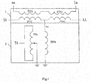
Figure 1 is the single-phase connection schematic diagram ofEmbodiment 1; -
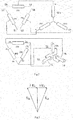
Figure 2 is the connection schematic diagram ofEmbodiment 1; -
Figure 3 is the phase-shift principle diagram of the invention; -
Figure 4 is the single-phase connection schematic diagram ofEmbodiment 2; -
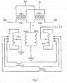
Figure 5 is the single-phase connection schematic diagram of Embodiment 3; - Wherein, 1, series transformer, 2, excitation transformer, SVA-SVC are phase A, phase B, phase C series coils, SVA1 and SVA2 are two coils of phase A series coil, EVA-EVC are phase A, phase B, phase C excitation coils, EVA1 and EVA2 are two coils the phase A excitation coil, TVA-TVC are phase A, phase B, phase C voltage regulation coils, TVA1 and TVA2 are two coils of phase A voltage regulation coil, TEVA-TEVC are the phase A, phase B, phase C voltage regulation excitation coils, TEVA1 and TEVA2 are the two coils of the phase A voltage regulation excitation coil, L1-L2 are the reactors.
- A high-capacity three-phase combined type phase-shift transformer, comprising three single-phase transformers, which are respectively used as a phase A, a phase B and a phase C and are combined with one another to form a three-phase transformer, each single-phase transformer comprises a
series transformer 1 and anexcitation transformer 2 that are arranged in a same oil tank and are two devices independent of each other. As shown inFig. 1 , take phase A as example, aseries transformer 1 comprises a series coil SVA and an excitation coil EVA, and leads out four terminals: a head end SA of the series coil and a tail end LA of the series coil being respectively taken as the power supply side input terminal and the load side output terminal, and the head end sa of the excitation coil and tail end la of the excitation coil are led out of the oil tank, theexcitation transformer 2 includes the voltage regulation excitation coil TEVA and the voltage regulation coil TVA, the head end ta of the voltage regulation excitation coil is connected to a center tap of a series coil SVA of aseries transformer 1 of a same phase, and a tail end is used as a neutral point to be led out of the oil tank, and the head end TA of the voltage regulation coil is led out of the oil tank, and a tail end is used as a neutral point to be led out of the oil tank. Phase A, phase B and phase C are same in structure. As shown inFigure 2 , when the three phases are running at the same time, the head end and tail end of the three-phase series coil SVA-SVC are connected into an angle, and the head end and tail end of the three-phase excitation coil EVA-EVC are connected into an angle; the three-phase voltage regulation excitation coils TEVA-TEVC are in star-shaped connection, three-phase voltage regulator coils TVA-TVC are in star-shaped connection. The head end and tail end of the three-phase excitation coil EVA-EVC are connected into an angle, and a head end of the voltage regulation coil of the third phase is connected to an angular joint of the every two phases, and the on-load tap switch is used to adjust the series connected turns number of voltage regulation coil to change the voltage value and the polarity in the voltage regulation coil, the phase shift principle is shown inFigure 3 , the voltage in voltage regulation coil provides the excitation for the steel core of series transformer, so that the excitation coil angularly connected in the series transformer generates a voltage that is 90° advanced or lag of the voltage of the voltage regulation excitation coil in same phase excitation transformer. Induced in the corresponding series coil, the voltage in excitation coil generate a voltage Δ U I and a voltage Δ U2 which have a phase difference of 90 ° with the same phase voltage regulation excitation coil. The voltage Δ U1 and the voltage Δ U2 make the power supply side voltage USA and the load side voltage ULA of the phase-shift transformer produce a phase angle change, while the input and output voltage are same, so as to realize the change of the phase angle between the power supply side and the load side voltage. By adjusting the position of the on-load tap switch, it can realize the adjustment between the phase difference and the advance or lag. - A high-capacity three-phase combined type phase-shift transformer, as shown in
Figure 4 , current limiting reactors L1, L2 are installed at the head end SA of the series coil and the tail end LA of the series coil to reduce the impact of the short circuit current on the phase-shift transformer in the grid. The other configurations are the same as theEmbodiment 1. - A high-capacity three-phase combined type phase-shift transformer, as shown in
Figure 5 , due to the large capacity of the phase-shift transformer, it adopts the structure of two series coils SVA1 and SVA2 in series connection, two excitation coils EVA1 and EVA2 in parallel connection, two voltage regulation excitation coils TEVA1 and TEVA2 in parallel connection, and two voltage regulation coils TVA1 and TVA2 in series connection. Due to the current in voltage regulation coil is too large, it adopts three on-load tap switches, and series connects current limiting reactors L1 and L2 in three branches for the balance of current distribution in three branches and limitation of the damage caused by possible short-circuit current to the on-load tap switch. The other configurations are the same as theEmbodiment 1.
Claims (3)
- A high-capacity three-phase combined type phase-shift transformer, characterized in that comprising three single-phase transformers, which are respectively used as a phase A, a phase B and a phase C and are combined with one another to form a three-phase transformer, each single-phase transformer comprises a series transformer and an excitation transformer that are arranged in a same oil tank and are two devices independent of each other, a series transformer of each phase comprises a series coil and an excitation coil, wherein a head end and a tail end of the series coil being respectively taken as the power supply side input terminal and the load side output terminal, and the head end and tail end of the excitation coil are led out of the oil tank, when the three phases are running at the same time, the head end and tail end of the three-phase series coil are connected into an angle, and the head end and tail end of the three-phase excitation coil are connected into an angle; the excitation transformer comprises a voltage regulation excitation coil and a voltage regulation coil, a head end of the voltage regulation excitation coil is connected to a center tap of a series coil of a series transformer of a same phase, and a tail end is used as a neutral point to be led out of the oil tank, a head end of the voltage regulation coil is led out of the oil tank to be connected to an angular joint of excitation coils of the other two phases, and a tail end is used as a neutral point to be led out of the oil tank, the voltage regulation coil is connected to a on-load tap switch which is used to adjust the voltage value and the polarity in voltage regulation coil, when the three-phase are running at the same time, the three-phase voltage regulation excitation coils are in star-shaped connection, three-phase voltage regulator coils are in star-shaped connection.
- The high-capacity three-phase combined type phase-shift transformer according to Claim 1, characterized in that wherein current limiting reactors are installed at the head end and the tail end of the series coil.
- The high-capacity three-phase combined type phase-shift transformer according to Claim 1 or 2, characterized in that wherein a current limiting reactor is series connected in the voltage regulation coil.
Applications Claiming Priority (2)
| Application Number | Priority Date | Filing Date | Title |
|---|---|---|---|
| CN201410744863.XA CN104465053B (en) | 2014-12-09 | 2014-12-09 | A kind of high-capacity three-phase combination type phase-shifting transformer |
| PCT/CN2015/096443 WO2016091123A1 (en) | 2014-12-09 | 2015-12-04 | High-capacity three-phase combined type phase-shift transformer |
Publications (3)
| Publication Number | Publication Date |
|---|---|
| EP3232452A1 true EP3232452A1 (en) | 2017-10-18 |
| EP3232452A4 EP3232452A4 (en) | 2018-01-31 |
| EP3232452B1 EP3232452B1 (en) | 2020-05-20 |
Family
ID=52910966
Family Applications (1)
| Application Number | Title | Priority Date | Filing Date |
|---|---|---|---|
| EP15868363.1A Active EP3232452B1 (en) | 2014-12-09 | 2015-12-04 | High-capacity three-phase combined type phase-shift transformer |
Country Status (3)
| Country | Link |
|---|---|
| EP (1) | EP3232452B1 (en) |
| CN (1) | CN104465053B (en) |
| WO (1) | WO2016091123A1 (en) |
Cited By (2)
| Publication number | Priority date | Publication date | Assignee | Title |
|---|---|---|---|---|
| EP3937198A1 (en) * | 2020-07-06 | 2022-01-12 | General Electric Technology GmbH | Power transformer assembly |
| WO2023099047A1 (en) * | 2021-12-01 | 2023-06-08 | Hitachi Energy Switzerland Ag | Transformer system for a direct current converter system |
Families Citing this family (15)
| Publication number | Priority date | Publication date | Assignee | Title |
|---|---|---|---|---|
| CN104465053B (en) * | 2014-12-09 | 2016-08-03 | 山东电力设备有限公司 | A kind of high-capacity three-phase combination type phase-shifting transformer |
| CN106053921B (en) * | 2016-08-02 | 2019-08-27 | 中国电力科学研究院 | Method for calculating stage voltage under load condition of symmetrical double-core phase-shifting transformer |
| CN107968576A (en) * | 2017-12-27 | 2018-04-27 | 国网宁夏电力有限公司检修公司 | A kind of phased high current source generator device |
| CN113496810B (en) * | 2020-04-07 | 2025-11-07 | 特变电工沈阳变压器集团有限公司 | Outdoor 500kV flexible direct current converter transformer with valve sleeve |
| CN111540594A (en) * | 2020-06-08 | 2020-08-14 | 保定天威保变电气股份有限公司 | An ultra-high voltage large-capacity phase-shifting transformer and its structural arrangement method |
| CN113077977A (en) * | 2021-04-13 | 2021-07-06 | 保定天威保变电气股份有限公司 | Novel high-capacity single-body high-impedance symmetrical voltage-regulating phase-shift phase transformer with additional reactor |
| CN113077978A (en) * | 2021-04-13 | 2021-07-06 | 保定天威保变电气股份有限公司 | Novel voltage-regulating phase-shifting transformer with high-capacity double-device height impedance and additional reactor |
| CN113283204B (en) * | 2021-05-19 | 2022-09-30 | 广东电网有限责任公司 | Electromagnetic transient modeling method and system for on-load voltage regulation controller |
| CN113611513A (en) * | 2021-07-23 | 2021-11-05 | 保定天威保变电气股份有限公司 | Phase modulation transformer with large phase shift angle |
| CN113611515B (en) * | 2021-09-03 | 2025-05-13 | 特变电工沈阳变压器集团有限公司 | Single-phase autotransformer |
| CN119153211A (en) * | 2023-06-16 | 2024-12-17 | 福州天宇电气股份有限公司 | Combined structure of high-voltage coil and positive and negative voltage regulating coil |
| CN118100167B (en) * | 2024-03-15 | 2025-11-18 | 国网福建省电力有限公司电力科学研究院 | An electromagnetic hybrid flexible networking device |
| CN118841243B (en) * | 2024-06-27 | 2025-08-19 | 南方电网科学研究院有限责任公司 | Single-core different-column self-coupling phase-shifting transformer and phase angle adjusting device |
| CN118507228B (en) * | 2024-07-15 | 2024-11-12 | 南方电网科学研究院有限责任公司 | A phase-angle symmetrical phase-shifting transformer and a phase-angle adjusting device |
| CN118507229B (en) * | 2024-07-15 | 2024-11-08 | 南方电网科学研究院有限责任公司 | Phase-shifting transformer and phase angle adjusting device thereof |
Family Cites Families (11)
| Publication number | Priority date | Publication date | Assignee | Title |
|---|---|---|---|---|
| JPS6328015A (en) * | 1986-07-22 | 1988-02-05 | Mitsubishi Electric Corp | Autotransformer |
| US5166597A (en) * | 1991-08-08 | 1992-11-24 | Electric Power Research Institute | Phase-shifting transformer system |
| CN2484625Y (en) * | 2001-06-01 | 2002-04-03 | 沈阳沈变中型变压器有限责任公司 | Voltage-regulating transformer |
| CN101354956B (en) * | 2008-05-28 | 2010-11-17 | 保定天威集团有限公司 | Large-capacity double-body phase-shifting transformer |
| CN101354957B (en) * | 2008-05-28 | 2011-03-09 | 保定天威集团有限公司 | Large-capacity double-body pressure-regulating phase-shifting transformer |
| CN101692398B (en) * | 2009-10-29 | 2012-06-27 | 保定天威集团有限公司 | High-voltage booster transformer |
| CN201829327U (en) * | 2010-06-30 | 2011-05-11 | 特变电工沈阳变压器集团有限公司 | Double body structure generator step-up transformer |
| KR101715296B1 (en) * | 2011-10-06 | 2017-03-13 | 현대중공업 주식회사 | The winding circuit of the phase shifting transformer having the voltage regulating function |
| KR20130081727A (en) * | 2011-12-28 | 2013-07-18 | 삼성전기주식회사 | Power supply apparatus including a function of protecting over-voltage |
| CN204215878U (en) * | 2014-12-09 | 2015-03-18 | 山东电力设备有限公司 | A kind of high-capacity three-phase composite type phase shifting transformer |
| CN104465053B (en) * | 2014-12-09 | 2016-08-03 | 山东电力设备有限公司 | A kind of high-capacity three-phase combination type phase-shifting transformer |
-
2014
- 2014-12-09 CN CN201410744863.XA patent/CN104465053B/en active Active
-
2015
- 2015-12-04 WO PCT/CN2015/096443 patent/WO2016091123A1/en not_active Ceased
- 2015-12-04 EP EP15868363.1A patent/EP3232452B1/en active Active
Cited By (4)
| Publication number | Priority date | Publication date | Assignee | Title |
|---|---|---|---|---|
| EP3937198A1 (en) * | 2020-07-06 | 2022-01-12 | General Electric Technology GmbH | Power transformer assembly |
| WO2022008227A1 (en) * | 2020-07-06 | 2022-01-13 | General Electric Technology Gmbh | Power transformer assembly |
| WO2023099047A1 (en) * | 2021-12-01 | 2023-06-08 | Hitachi Energy Switzerland Ag | Transformer system for a direct current converter system |
| US12347599B2 (en) | 2021-12-01 | 2025-07-01 | Hitachi Energy Ltd | Transformer system for a direct current converter system |
Also Published As
| Publication number | Publication date |
|---|---|
| CN104465053B (en) | 2016-08-03 |
| WO2016091123A1 (en) | 2016-06-16 |
| EP3232452B1 (en) | 2020-05-20 |
| CN104465053A (en) | 2015-03-25 |
| EP3232452A4 (en) | 2018-01-31 |
Similar Documents
| Publication | Publication Date | Title |
|---|---|---|
| EP3232452B1 (en) | High-capacity three-phase combined type phase-shift transformer | |
| CN110535139B (en) | A wide voltage regulating device | |
| CN110544580A (en) | Main transformer and boosting system of offshore wind power plant boosting station | |
| JP5118397B2 (en) | Current limiting device | |
| CN205303137U (en) | Auto transformer with voltage regulation coil | |
| RU2585007C1 (en) | Device for control of reactive power of electric network (versions) | |
| CN202758723U (en) | De-icing transformer | |
| CN205211561U (en) | High pressure star angular transformation on -load voltage -regulating transformer's winding wiring structure | |
| CN103928225B (en) | A kind of method transforming 220kV off circuit tap changing transfor mer device body as ULTC device body | |
| CN203732579U (en) | Voltage drop simulation generator used for measuring wind driven generator | |
| CN204215878U (en) | A kind of high-capacity three-phase composite type phase shifting transformer | |
| CN203277069U (en) | Novel electric energy optimizing machine | |
| CN201369705Y (en) | Transformer with partial winding voltage adjustment | |
| CN202422974U (en) | On-load voltage regulation transformer | |
| CN113809753A (en) | Voltage stabilizer for encapsulated coil transformer | |
| CN216215907U (en) | Closed loop phase correction device for power system | |
| CN204289045U (en) | A kind of multi-functional winding construction for transformer | |
| CN204257354U (en) | High-voltage dual-voltage does variant shunting device of transformer | |
| CN205264475U (en) | Novel 35kV becomes oily formula grounding transformer of magnetic flow | |
| CN204442006U (en) | Y connects the balanced source-taking apparatus of voltage transformer open delta | |
| KR101565392B1 (en) | Three-phase transformer using two-phase | |
| CN103903843B (en) | Zigzag connection type stepless adjustable voltage transformer | |
| CN203631289U (en) | Low-voltage on-load regulating transformer | |
| Schmid et al. | On-load voltage regulation in the low voltage grid | |
| RU168504U1 (en) | TRANSFORMER - TWO-PHASE VOLTAGE CONVERTER TO THREE-PHASE |
Legal Events
| Date | Code | Title | Description |
|---|---|---|---|
| STAA | Information on the status of an ep patent application or granted ep patent |
Free format text: STATUS: THE INTERNATIONAL PUBLICATION HAS BEEN MADE |
|
| PUAI | Public reference made under article 153(3) epc to a published international application that has entered the european phase |
Free format text: ORIGINAL CODE: 0009012 |
|
| STAA | Information on the status of an ep patent application or granted ep patent |
Free format text: STATUS: REQUEST FOR EXAMINATION WAS MADE |
|
| 17P | Request for examination filed |
Effective date: 20170707 |
|
| AK | Designated contracting states |
Kind code of ref document: A1 Designated state(s): AL AT BE BG CH CY CZ DE DK EE ES FI FR GB GR HR HU IE IS IT LI LT LU LV MC MK MT NL NO PL PT RO RS SE SI SK SM TR |
|
| AX | Request for extension of the european patent |
Extension state: BA ME |
|
| A4 | Supplementary search report drawn up and despatched |
Effective date: 20180105 |
|
| RIC1 | Information provided on ipc code assigned before grant |
Ipc: H01F 30/12 20060101ALI20171222BHEP Ipc: H01F 29/00 20060101AFI20171222BHEP Ipc: H01F 27/29 20060101ALI20171222BHEP Ipc: H01F 27/28 20060101ALI20171222BHEP Ipc: H01F 27/42 20060101ALI20171222BHEP Ipc: H02P 13/06 20060101ALI20171222BHEP Ipc: H01F 27/40 20060101ALI20171222BHEP |
|
| DAV | Request for validation of the european patent (deleted) | ||
| DAX | Request for extension of the european patent (deleted) | ||
| GRAP | Despatch of communication of intention to grant a patent |
Free format text: ORIGINAL CODE: EPIDOSNIGR1 |
|
| STAA | Information on the status of an ep patent application or granted ep patent |
Free format text: STATUS: GRANT OF PATENT IS INTENDED |
|
| RIC1 | Information provided on ipc code assigned before grant |
Ipc: H01F 27/28 20060101ALI20191216BHEP Ipc: H02P 13/06 20060101ALI20191216BHEP Ipc: H01F 27/42 20060101ALI20191216BHEP Ipc: H01F 27/40 20060101ALI20191216BHEP Ipc: H01F 30/12 20060101ALI20191216BHEP Ipc: H01F 27/29 20060101ALI20191216BHEP Ipc: H01F 29/00 20060101AFI20191216BHEP |
|
| INTG | Intention to grant announced |
Effective date: 20200117 |
|
| GRAS | Grant fee paid |
Free format text: ORIGINAL CODE: EPIDOSNIGR3 |
|
| GRAA | (expected) grant |
Free format text: ORIGINAL CODE: 0009210 |
|
| STAA | Information on the status of an ep patent application or granted ep patent |
Free format text: STATUS: THE PATENT HAS BEEN GRANTED |
|
| RAP1 | Party data changed (applicant data changed or rights of an application transferred) |
Owner name: SHANDONG ELECTRICAL ENGINEERING & EQUIPMENT GROUP CO., LTD. Owner name: SHANDONG POWER EQUIPMENT CO., LTD. |
|
| AK | Designated contracting states |
Kind code of ref document: B1 Designated state(s): AL AT BE BG CH CY CZ DE DK EE ES FI FR GB GR HR HU IE IS IT LI LT LU LV MC MK MT NL NO PL PT RO RS SE SI SK SM TR |
|
| REG | Reference to a national code |
Ref country code: GB Ref legal event code: FG4D |
|
| REG | Reference to a national code |
Ref country code: CH Ref legal event code: EP |
|
| REG | Reference to a national code |
Ref country code: DE Ref legal event code: R096 Ref document number: 602015053170 Country of ref document: DE |
|
| REG | Reference to a national code |
Ref country code: AT Ref legal event code: REF Ref document number: 1273153 Country of ref document: AT Kind code of ref document: T Effective date: 20200615 |
|
| REG | Reference to a national code |
Ref country code: CH Ref legal event code: NV Representative=s name: BOVARD AG PATENT- UND MARKENANWAELTE, CH |
|
| REG | Reference to a national code |
Ref country code: NL Ref legal event code: FP |
|
| REG | Reference to a national code |
Ref country code: LT Ref legal event code: MG4D |
|
| PG25 | Lapsed in a contracting state [announced via postgrant information from national office to epo] |
Ref country code: PT Free format text: LAPSE BECAUSE OF FAILURE TO SUBMIT A TRANSLATION OF THE DESCRIPTION OR TO PAY THE FEE WITHIN THE PRESCRIBED TIME-LIMIT Effective date: 20200921 Ref country code: IS Free format text: LAPSE BECAUSE OF FAILURE TO SUBMIT A TRANSLATION OF THE DESCRIPTION OR TO PAY THE FEE WITHIN THE PRESCRIBED TIME-LIMIT Effective date: 20200920 Ref country code: SE Free format text: LAPSE BECAUSE OF FAILURE TO SUBMIT A TRANSLATION OF THE DESCRIPTION OR TO PAY THE FEE WITHIN THE PRESCRIBED TIME-LIMIT Effective date: 20200520 Ref country code: LT Free format text: LAPSE BECAUSE OF FAILURE TO SUBMIT A TRANSLATION OF THE DESCRIPTION OR TO PAY THE FEE WITHIN THE PRESCRIBED TIME-LIMIT Effective date: 20200520 Ref country code: FI Free format text: LAPSE BECAUSE OF FAILURE TO SUBMIT A TRANSLATION OF THE DESCRIPTION OR TO PAY THE FEE WITHIN THE PRESCRIBED TIME-LIMIT Effective date: 20200520 Ref country code: NO Free format text: LAPSE BECAUSE OF FAILURE TO SUBMIT A TRANSLATION OF THE DESCRIPTION OR TO PAY THE FEE WITHIN THE PRESCRIBED TIME-LIMIT Effective date: 20200820 Ref country code: GR Free format text: LAPSE BECAUSE OF FAILURE TO SUBMIT A TRANSLATION OF THE DESCRIPTION OR TO PAY THE FEE WITHIN THE PRESCRIBED TIME-LIMIT Effective date: 20200821 |
|
| PG25 | Lapsed in a contracting state [announced via postgrant information from national office to epo] |
Ref country code: BG Free format text: LAPSE BECAUSE OF FAILURE TO SUBMIT A TRANSLATION OF THE DESCRIPTION OR TO PAY THE FEE WITHIN THE PRESCRIBED TIME-LIMIT Effective date: 20200820 Ref country code: RS Free format text: LAPSE BECAUSE OF FAILURE TO SUBMIT A TRANSLATION OF THE DESCRIPTION OR TO PAY THE FEE WITHIN THE PRESCRIBED TIME-LIMIT Effective date: 20200520 Ref country code: LV Free format text: LAPSE BECAUSE OF FAILURE TO SUBMIT A TRANSLATION OF THE DESCRIPTION OR TO PAY THE FEE WITHIN THE PRESCRIBED TIME-LIMIT Effective date: 20200520 Ref country code: HR Free format text: LAPSE BECAUSE OF FAILURE TO SUBMIT A TRANSLATION OF THE DESCRIPTION OR TO PAY THE FEE WITHIN THE PRESCRIBED TIME-LIMIT Effective date: 20200520 |
|
| REG | Reference to a national code |
Ref country code: AT Ref legal event code: MK05 Ref document number: 1273153 Country of ref document: AT Kind code of ref document: T Effective date: 20200520 |
|
| PG25 | Lapsed in a contracting state [announced via postgrant information from national office to epo] |
Ref country code: AL Free format text: LAPSE BECAUSE OF FAILURE TO SUBMIT A TRANSLATION OF THE DESCRIPTION OR TO PAY THE FEE WITHIN THE PRESCRIBED TIME-LIMIT Effective date: 20200520 |
|
| PG25 | Lapsed in a contracting state [announced via postgrant information from national office to epo] |
Ref country code: IT Free format text: LAPSE BECAUSE OF FAILURE TO SUBMIT A TRANSLATION OF THE DESCRIPTION OR TO PAY THE FEE WITHIN THE PRESCRIBED TIME-LIMIT Effective date: 20200520 Ref country code: SM Free format text: LAPSE BECAUSE OF FAILURE TO SUBMIT A TRANSLATION OF THE DESCRIPTION OR TO PAY THE FEE WITHIN THE PRESCRIBED TIME-LIMIT Effective date: 20200520 Ref country code: EE Free format text: LAPSE BECAUSE OF FAILURE TO SUBMIT A TRANSLATION OF THE DESCRIPTION OR TO PAY THE FEE WITHIN THE PRESCRIBED TIME-LIMIT Effective date: 20200520 Ref country code: AT Free format text: LAPSE BECAUSE OF FAILURE TO SUBMIT A TRANSLATION OF THE DESCRIPTION OR TO PAY THE FEE WITHIN THE PRESCRIBED TIME-LIMIT Effective date: 20200520 Ref country code: DK Free format text: LAPSE BECAUSE OF FAILURE TO SUBMIT A TRANSLATION OF THE DESCRIPTION OR TO PAY THE FEE WITHIN THE PRESCRIBED TIME-LIMIT Effective date: 20200520 Ref country code: RO Free format text: LAPSE BECAUSE OF FAILURE TO SUBMIT A TRANSLATION OF THE DESCRIPTION OR TO PAY THE FEE WITHIN THE PRESCRIBED TIME-LIMIT Effective date: 20200520 Ref country code: CZ Free format text: LAPSE BECAUSE OF FAILURE TO SUBMIT A TRANSLATION OF THE DESCRIPTION OR TO PAY THE FEE WITHIN THE PRESCRIBED TIME-LIMIT Effective date: 20200520 Ref country code: ES Free format text: LAPSE BECAUSE OF FAILURE TO SUBMIT A TRANSLATION OF THE DESCRIPTION OR TO PAY THE FEE WITHIN THE PRESCRIBED TIME-LIMIT Effective date: 20200520 |
|
| PGFP | Annual fee paid to national office [announced via postgrant information from national office to epo] |
Ref country code: FR Payment date: 20201228 Year of fee payment: 6 Ref country code: CH Payment date: 20201227 Year of fee payment: 6 Ref country code: GB Payment date: 20201227 Year of fee payment: 6 |
|
| REG | Reference to a national code |
Ref country code: DE Ref legal event code: R097 Ref document number: 602015053170 Country of ref document: DE |
|
| PG25 | Lapsed in a contracting state [announced via postgrant information from national office to epo] |
Ref country code: PL Free format text: LAPSE BECAUSE OF FAILURE TO SUBMIT A TRANSLATION OF THE DESCRIPTION OR TO PAY THE FEE WITHIN THE PRESCRIBED TIME-LIMIT Effective date: 20200520 Ref country code: SK Free format text: LAPSE BECAUSE OF FAILURE TO SUBMIT A TRANSLATION OF THE DESCRIPTION OR TO PAY THE FEE WITHIN THE PRESCRIBED TIME-LIMIT Effective date: 20200520 |
|
| PLBE | No opposition filed within time limit |
Free format text: ORIGINAL CODE: 0009261 |
|
| STAA | Information on the status of an ep patent application or granted ep patent |
Free format text: STATUS: NO OPPOSITION FILED WITHIN TIME LIMIT |
|
| PGFP | Annual fee paid to national office [announced via postgrant information from national office to epo] |
Ref country code: NL Payment date: 20201223 Year of fee payment: 6 |
|
| 26N | No opposition filed |
Effective date: 20210223 |
|
| PG25 | Lapsed in a contracting state [announced via postgrant information from national office to epo] |
Ref country code: SI Free format text: LAPSE BECAUSE OF FAILURE TO SUBMIT A TRANSLATION OF THE DESCRIPTION OR TO PAY THE FEE WITHIN THE PRESCRIBED TIME-LIMIT Effective date: 20200520 |
|
| PGFP | Annual fee paid to national office [announced via postgrant information from national office to epo] |
Ref country code: DE Payment date: 20201229 Year of fee payment: 6 |
|
| PG25 | Lapsed in a contracting state [announced via postgrant information from national office to epo] |
Ref country code: MC Free format text: LAPSE BECAUSE OF FAILURE TO SUBMIT A TRANSLATION OF THE DESCRIPTION OR TO PAY THE FEE WITHIN THE PRESCRIBED TIME-LIMIT Effective date: 20200520 |
|
| REG | Reference to a national code |
Ref country code: BE Ref legal event code: MM Effective date: 20201231 |
|
| PG25 | Lapsed in a contracting state [announced via postgrant information from national office to epo] |
Ref country code: LU Free format text: LAPSE BECAUSE OF NON-PAYMENT OF DUE FEES Effective date: 20201204 Ref country code: IE Free format text: LAPSE BECAUSE OF NON-PAYMENT OF DUE FEES Effective date: 20201204 |
|
| PG25 | Lapsed in a contracting state [announced via postgrant information from national office to epo] |
Ref country code: TR Free format text: LAPSE BECAUSE OF FAILURE TO SUBMIT A TRANSLATION OF THE DESCRIPTION OR TO PAY THE FEE WITHIN THE PRESCRIBED TIME-LIMIT Effective date: 20200520 Ref country code: MT Free format text: LAPSE BECAUSE OF FAILURE TO SUBMIT A TRANSLATION OF THE DESCRIPTION OR TO PAY THE FEE WITHIN THE PRESCRIBED TIME-LIMIT Effective date: 20200520 Ref country code: CY Free format text: LAPSE BECAUSE OF FAILURE TO SUBMIT A TRANSLATION OF THE DESCRIPTION OR TO PAY THE FEE WITHIN THE PRESCRIBED TIME-LIMIT Effective date: 20200520 |
|
| PG25 | Lapsed in a contracting state [announced via postgrant information from national office to epo] |
Ref country code: MK Free format text: LAPSE BECAUSE OF FAILURE TO SUBMIT A TRANSLATION OF THE DESCRIPTION OR TO PAY THE FEE WITHIN THE PRESCRIBED TIME-LIMIT Effective date: 20200520 |
|
| REG | Reference to a national code |
Ref country code: DE Ref legal event code: R119 Ref document number: 602015053170 Country of ref document: DE |
|
| PG25 | Lapsed in a contracting state [announced via postgrant information from national office to epo] |
Ref country code: BE Free format text: LAPSE BECAUSE OF NON-PAYMENT OF DUE FEES Effective date: 20201231 |
|
| REG | Reference to a national code |
Ref country code: CH Ref legal event code: PL |
|
| REG | Reference to a national code |
Ref country code: NL Ref legal event code: MM Effective date: 20220101 |
|
| GBPC | Gb: european patent ceased through non-payment of renewal fee |
Effective date: 20211204 |
|
| PG25 | Lapsed in a contracting state [announced via postgrant information from national office to epo] |
Ref country code: NL Free format text: LAPSE BECAUSE OF NON-PAYMENT OF DUE FEES Effective date: 20220101 |
|
| PG25 | Lapsed in a contracting state [announced via postgrant information from national office to epo] |
Ref country code: GB Free format text: LAPSE BECAUSE OF NON-PAYMENT OF DUE FEES Effective date: 20211204 Ref country code: DE Free format text: LAPSE BECAUSE OF NON-PAYMENT OF DUE FEES Effective date: 20220701 |
|
| PG25 | Lapsed in a contracting state [announced via postgrant information from national office to epo] |
Ref country code: FR Free format text: LAPSE BECAUSE OF NON-PAYMENT OF DUE FEES Effective date: 20211231 |
|
| PG25 | Lapsed in a contracting state [announced via postgrant information from national office to epo] |
Ref country code: LI Free format text: LAPSE BECAUSE OF NON-PAYMENT OF DUE FEES Effective date: 20211231 Ref country code: CH Free format text: LAPSE BECAUSE OF NON-PAYMENT OF DUE FEES Effective date: 20211231 |