EP4429945B1 - Wellenangetriebene fahrzeuge - Google Patents
Wellenangetriebene fahrzeuge Download PDFInfo
- Publication number
- EP4429945B1 EP4429945B1 EP22802700.9A EP22802700A EP4429945B1 EP 4429945 B1 EP4429945 B1 EP 4429945B1 EP 22802700 A EP22802700 A EP 22802700A EP 4429945 B1 EP4429945 B1 EP 4429945B1
- Authority
- EP
- European Patent Office
- Prior art keywords
- vehicle
- hull
- hydrofoil
- fluid
- wave
- Prior art date
- Legal status (The legal status is an assumption and is not a legal conclusion. Google has not performed a legal analysis and makes no representation as to the accuracy of the status listed.)
- Active
Links
Images


Classifications
-
- B—PERFORMING OPERATIONS; TRANSPORTING
- B63—SHIPS OR OTHER WATERBORNE VESSELS; RELATED EQUIPMENT
- B63H—MARINE PROPULSION OR STEERING
- B63H19/00—Marine propulsion not otherwise provided for
- B63H19/02—Marine propulsion not otherwise provided for by using energy derived from movement of ambient water, e.g. from rolling or pitching of vessels
-
- B—PERFORMING OPERATIONS; TRANSPORTING
- B63—SHIPS OR OTHER WATERBORNE VESSELS; RELATED EQUIPMENT
- B63B—SHIPS OR OTHER WATERBORNE VESSELS; EQUIPMENT FOR SHIPPING
- B63B1/00—Hydrodynamic or hydrostatic features of hulls or of hydrofoils
- B63B1/16—Hydrodynamic or hydrostatic features of hulls or of hydrofoils deriving additional lift from hydrodynamic forces
- B63B1/24—Hydrodynamic or hydrostatic features of hulls or of hydrofoils deriving additional lift from hydrodynamic forces of hydrofoil type
- B63B1/26—Hydrodynamic or hydrostatic features of hulls or of hydrofoils deriving additional lift from hydrodynamic forces of hydrofoil type having more than one hydrofoil
-
- B—PERFORMING OPERATIONS; TRANSPORTING
- B63—SHIPS OR OTHER WATERBORNE VESSELS; RELATED EQUIPMENT
- B63B—SHIPS OR OTHER WATERBORNE VESSELS; EQUIPMENT FOR SHIPPING
- B63B1/00—Hydrodynamic or hydrostatic features of hulls or of hydrofoils
- B63B1/16—Hydrodynamic or hydrostatic features of hulls or of hydrofoils deriving additional lift from hydrodynamic forces
- B63B1/24—Hydrodynamic or hydrostatic features of hulls or of hydrofoils deriving additional lift from hydrodynamic forces of hydrofoil type
- B63B1/248—Shape, hydrodynamic features, construction of the foil
-
- B—PERFORMING OPERATIONS; TRANSPORTING
- B63—SHIPS OR OTHER WATERBORNE VESSELS; RELATED EQUIPMENT
- B63B—SHIPS OR OTHER WATERBORNE VESSELS; EQUIPMENT FOR SHIPPING
- B63B1/00—Hydrodynamic or hydrostatic features of hulls or of hydrofoils
- B63B1/16—Hydrodynamic or hydrostatic features of hulls or of hydrofoils deriving additional lift from hydrodynamic forces
- B63B1/24—Hydrodynamic or hydrostatic features of hulls or of hydrofoils deriving additional lift from hydrodynamic forces of hydrofoil type
- B63B1/28—Hydrodynamic or hydrostatic features of hulls or of hydrofoils deriving additional lift from hydrodynamic forces of hydrofoil type with movable hydrofoils
- B63B1/30—Hydrodynamic or hydrostatic features of hulls or of hydrofoils deriving additional lift from hydrodynamic forces of hydrofoil type with movable hydrofoils retracting or folding
-
- B—PERFORMING OPERATIONS; TRANSPORTING
- B63—SHIPS OR OTHER WATERBORNE VESSELS; RELATED EQUIPMENT
- B63G—OFFENSIVE OR DEFENSIVE ARRANGEMENTS ON VESSELS; MINE-LAYING; MINE-SWEEPING; SUBMARINES; AIRCRAFT CARRIERS
- B63G8/00—Underwater vessels, e.g. submarines; Equipment specially adapted therefor
- B63G8/08—Propulsion
-
- B—PERFORMING OPERATIONS; TRANSPORTING
- B63—SHIPS OR OTHER WATERBORNE VESSELS; RELATED EQUIPMENT
- B63G—OFFENSIVE OR DEFENSIVE ARRANGEMENTS ON VESSELS; MINE-LAYING; MINE-SWEEPING; SUBMARINES; AIRCRAFT CARRIERS
- B63G8/00—Underwater vessels, e.g. submarines; Equipment specially adapted therefor
- B63G8/14—Control of attitude or depth
- B63G8/20—Steering equipment
-
- B—PERFORMING OPERATIONS; TRANSPORTING
- B63—SHIPS OR OTHER WATERBORNE VESSELS; RELATED EQUIPMENT
- B63G—OFFENSIVE OR DEFENSIVE ARRANGEMENTS ON VESSELS; MINE-LAYING; MINE-SWEEPING; SUBMARINES; AIRCRAFT CARRIERS
- B63G8/00—Underwater vessels, e.g. submarines; Equipment specially adapted therefor
- B63G8/14—Control of attitude or depth
- B63G8/22—Adjustment of buoyancy by water ballasting; Emptying equipment for ballast tanks
-
- B—PERFORMING OPERATIONS; TRANSPORTING
- B63—SHIPS OR OTHER WATERBORNE VESSELS; RELATED EQUIPMENT
- B63B—SHIPS OR OTHER WATERBORNE VESSELS; EQUIPMENT FOR SHIPPING
- B63B35/00—Vessels or similar floating structures specially adapted for specific purposes and not otherwise provided for
- B63B2035/006—Unmanned surface vessels, e.g. remotely controlled
- B63B2035/007—Unmanned surface vessels, e.g. remotely controlled autonomously operating
-
- B—PERFORMING OPERATIONS; TRANSPORTING
- B63—SHIPS OR OTHER WATERBORNE VESSELS; RELATED EQUIPMENT
- B63B—SHIPS OR OTHER WATERBORNE VESSELS; EQUIPMENT FOR SHIPPING
- B63B2207/00—Buoyancy or ballast means
- B63B2207/02—Variable ballast or buoyancy
-
- B—PERFORMING OPERATIONS; TRANSPORTING
- B63—SHIPS OR OTHER WATERBORNE VESSELS; RELATED EQUIPMENT
- B63G—OFFENSIVE OR DEFENSIVE ARRANGEMENTS ON VESSELS; MINE-LAYING; MINE-SWEEPING; SUBMARINES; AIRCRAFT CARRIERS
- B63G8/00—Underwater vessels, e.g. submarines; Equipment specially adapted therefor
- B63G8/001—Underwater vessels adapted for special purposes, e.g. unmanned underwater vessels; Equipment specially adapted therefor, e.g. docking stations
- B63G2008/002—Underwater vessels adapted for special purposes, e.g. unmanned underwater vessels; Equipment specially adapted therefor, e.g. docking stations unmanned
- B63G2008/004—Underwater vessels adapted for special purposes, e.g. unmanned underwater vessels; Equipment specially adapted therefor, e.g. docking stations unmanned autonomously operating
-
- B—PERFORMING OPERATIONS; TRANSPORTING
- B63—SHIPS OR OTHER WATERBORNE VESSELS; RELATED EQUIPMENT
- B63J—AUXILIARIES ON VESSELS
- B63J3/00—Driving of auxiliaries
- B63J2003/001—Driving of auxiliaries characterised by type of power supply, or power transmission, e.g. by using electric power or steam
- B63J2003/002—Driving of auxiliaries characterised by type of power supply, or power transmission, e.g. by using electric power or steam by using electric power
- B63J2003/003—Driving of auxiliaries characterised by type of power supply, or power transmission, e.g. by using electric power or steam by using electric power using photovoltaic power generation, e.g. using solar panels
Definitions
- the present application relates to wave-propelled vehicles, in particular, to vehicles that generate forward thrust from the action of surface gravity waves present at the surface of a body of fluid.
- the hydrodynamic device in this type of mechanism may experience a periodic vertical velocity different to the surrounding vertical velocity of the fluid, with the relative velocity related to the length of the elongate member.
- Implementations of this type of mechanism may feature a floating body designed to closely follow the surface of the fluid, i.e., a body with high hydrodynamic stiffness, such as a lowdensity, surfboard-like body.
- the elongate member may be a flexible tensile member, such as a tether.
- generally identifiable in wave-propelled vehicles of the prior art is at least one body designed either to maximise or minimise its response to waves, and a separate planar hydrofoil element or elements anchored to the body to convert relative oscillatory motion, between the hydrofoil element or elements and the surrounding fluid, into thrust, via a flapping motion involving resilient deformation, hinged pitching, or winglike flapping of the hydrofoil element or elements.
- Allocating the wave-response and thrust-production functions to separate physical components in this manner offers the advantage of being able to optimise each element independently for its function (e.g., by optimising the body for either maximal in-phase or out-of-phase oscillatory response to waves, or for minimal response to waves, and optimising the hydrofoil element or elements for thrust production).
- this separation of functions means that each element does not tend to contribute to, and may in fact interfere with, the function of the other.
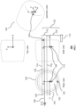
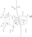
- FIG. 1 there is shown a view 100 of a wave-propelled vehicle 102 comprising a hull 104 adapted to float at the free surface 106 of a body of fluid.
- a hull 104 adapted to float at the free surface 106 of a body of fluid.
- axes X, Y and Z originating at the vehicle's centre of gravity 108.
- the hull 104 has a centre of buoyancy 110 disposed vertically aligned with the centre of gravity 108.
- the figure shows the centre of gravity 108 disposed above the centre of buoyancy 110, but one skilled in the art will appreciate that such a vehicle may have a centre of gravity disposed above, at the same elevation as, or below the centre of buoyancy whilst achieving at least one, or both, of: desirable wave-response characteristic(s) and selfrighting characteristic(s).
- the X-axis coincides with the longitudinal axis of the hull 104.
- the origin of the axis system remains pinned to the centre of gravity 108
- the X-Y plane remains horizontal
- the Z-axis remains vertical
- the projection of the hull's longitudinal axis onto the X-Y plane coincides with the X-axis.
- the hull may oscillate in or about the X, Y and Z axes.
- Waves travelling through the body of fluid may cause the hull 104 to oscillate in or about any of the axes defined above.
- parts of the hull may alternately submerge below or broach the surface 106.
- An upper extent 114 and a lower extent 116 of this "dynamic immersion" of the hull is defined, thus defining an upper hull portion 118 of the hull; a lower hull portion 120 of the hull may be defined as that portion of the hull below the lower extent 116 of dynamic immersion.
- he upper hull portion can be defined as that portion of the hull that periodically plunges through the free surface of the body of fluid under the action of surface waves; the upper hull portion comprising a hydrofoil portion.
- the lower hull portion can be defined as that portion of the hull that remains below the free surface despite the action of the surface waves; the lower hull portion comprising a hydrofoil structure; the hydrofoil structure comprising a hydrofoil portion.
- the surface waves can have a given character describable, by way of example only, according to any of the following taken jointly and severally in any and all permutations: a peak period; a zero-crossing period; a significant wave height; a mean wave height; a non -directional wave spectrum; and a directional wave spectrum.
- the upper hull portion 118 and the lower hull portion 120 of the hull define the operative volume 122 of the hull.
- the upper hull portion 118 has a leading position 124; a leading position of the hull or of a portion of the hull is a prominently positioned forward location of the hull, which would be recognised by one skilled in the art as falling, by way of example only, on the leading edge of a hydrofoil portion of the hull. Projected onto a frontal plane of the vehicle, the set of all the leading positions of the hull, or of a continuous portion of the hull, forms a continuous one-dimensional, two-dimensional, or both one- and two-dimensional figure.
- leading edge of a hydrofoil portion with a rounded or sharp leading edge would form a one-dimensional figure (i.e., a curve) when projected in this way
- leading positions of a longitudinally aligned cylinder would form a circular disc when projected in this way.
- the lower hull portion 120 of the hull has a trailing position 126; a trailing position of the hull or a portion of the hull is a prominently positioned rearward location of the hull, which would be recognised by one skilled in the art as falling, by way of example only, on the trailing edge of a hydrofoil portion of the hull.
- Projected onto a frontal planeof the vehicle the set of all the trailing positions of the hull, or of a continuous portion of the hull, forms a continuous one-dimensional, two-dimensional, or both one- and two-dimensional figure.
- a perfectly sharp trailing edge of a hydrofoil portion would form a one-dimensional figure (i.e., a curve) when projected in this way; the trailing positions of a longitudinally aligned cylinder would forma circular disc when projected in this way.
- the upper hull portion 118 comprises hydrofoil portions 128 and 128' each spanning a horizontal extent as well as a vertical extent.
- the lower hull portion comprises a hydrofoil portion 130 spanning a horizontal extent as well as a vertical extent, hydrofoil portion 130 defining an upwardly directed concavity 132 when viewed from the front or rear.
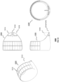
- a view 300 of a wave-propelled vehicle 302 comprising an upper hull portion 304 and a lower hull portion 306.
- the upper hull portion 304 comprises hydrofoil portions 308 and 308', each spanning a vertical extent.
- the lower hull portion comprises a hydrofoil portion 310 spanning a horizontal extent as well as a vertical extent.
- the hydrofoil portion 310 defines a vertically directed concavity 312 when viewed from the front or rear.
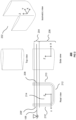
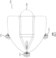
- a view 400 of a wave-propelled vehicle 402 comprising an upper hull portion 404 and a lower hull portion 406.
- the upper hull portion 404 comprises hydrofoil portions 408 and 408', each spanning a vertical extent.
- the lower hull portion comprises hydrofoil portions 410 and 410', each spanning a vertical extent, and a hydrofoil portion 412 spanning a horizontal extent.
- the hydrofoil portions 410, 410' and 412 define a vertically directed concavity 414 when viewed from the front or rear.
- the upper hull portion further comprises a hydrofoil portion 416 spanning a horizontal extent.
- constructing the hull of the vehicle 402 as a substantially rigid body having a longitudinally aligned conduit of closed shape when viewed from the front or rear of the vehicle may have a structural benefit, and may provide a convenient location for the mounting of, for example, photovoltaic cells.
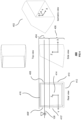
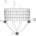
- a view 500 of a wave-propelled vehicle 502 comprising an upper hull portion 504 and a lower hull portion 506.
- the upper hull portion 504 comprises hydrofoil portions 508 and 508' each spanning a horizontal extent as well as a vertical extent.
- the lower hull portion comprises a hydrofoil portion 510 spanning a horizontal extent as well as a vertical extent.
- the hydrofoil portion 510 provides a vertically directed concavity 512 when viewed from the front or rear and, together with the rest of the hull, forms part of an annular hull profile.
- hydrofoil portion of the vehicle may generate thrust.
- a hydrofoil portion may experience a time-varying angle of attack and velocity relative to the surrounding fluid such that, on average, the hydrofoil portion generates thrust in the direction of travel, as one skilled in the art will appreciate from steady-state aerodynamic and hydrodynamic theory.
- thrust production by an oscillating hydrofoil portion may be considered as being due to the creation of a favourable (i.e., thrust-producing) unsteady wake, such as a reverse von Kármán street of shed vortices.
- the lower hull portion comprises a hydrofoil structure comprising one or more than one hydrofoil portion.
- the hydrofoil structure of the lower hull portion is substantially non-planar, providing a vertically directed concavity when viewed from the front or rear of the vehicle.
- a concavity may exist where, if all leading or all trailing positions of the hydrofoil structure of the lower hull portion are projected onto a frontal plane of the vehicle, there exists two points of equal altitude on the projection, such that an area is generally defined by the projection and a horizontal line segment connecting the two points.
- the non-planar arrangement of the hydrofoil structure of the lower hull portion can improve the efficiency with which a given hydrofoil portion produces thrust, reducing drag or damping that might otherwise be present due to the tip losses generally experienced by thrust-producing, low aspect ratio, planar hydrofoils.
- This enables efficient realisation of large hydrofoil chords relative to the length of the vehicle, such that small amplitude rotational oscillations of the vehicle may correspond to relatively large trailing edge motions. Large-amplitude trailing edge motions will be recognised as desirable for flapping foil propulsion under various operating conditions of a vehicle.
- a hydrofoil portion having vertical extent of the lower hull portion of any of the vehicles according to the examples described may be conveniently extended to provide an element of the upper hull (for example, by extending said hydrofoil portion up through the equilibrium free surface). This allows the resulting vertically extending hydrofoil portion of the upper hull portion to provide a hydrodynamic stiffness component of the vehicle's wave response dynamics. It will be appreciated that such a vertically extending hydrofoil portion of the upper hull portion may provide hull volume about the free surface with great hydrodynamic efficiency, i.e., low drag in forward motion. It will be appreciated that extending a hydrofoil portion in this way means that a tip of the hydrofoil portion may be prevented from exposure to the fluid, reducing tip losses where the hydrofoil portion is thrust-producing.
- one or more than one hydrofoil portion, having vertical extent, horizontal extent, or a combination of vertical and horizontal extents, of the upper hull portion may account for all of the volume of the upper hull portion.
- This has the benefit that time-varying hydrodynamic, hydrostatic, or combined hydrodynamic and hydrostatic forces applied to the upper hull portion due to the action of waves may act on the upper hull portion with minimal resistance to forward motion.
- further examples of the invention may be realised wherein simply a substantial proportion of the volume is accounted for by said hydrofoil portion or portions of the upper hull portion, for example, a majority of the volume. Therefore, it will be appreciated that the examples can provide a blended body that simultaneously performs the dual functions of providing a wave-responsive body and thrust-producing hydrofoils.
- the blended body can be a unitary body.
- a hydrofoil portion of any of the vehicles according to the examples described may have an aerofoil cross-section, for example, a NACA symmetrical aerofoil cross-section, such as a NACA0015 aerofoil cross-section.
- a hydrofoil portion of any of the vehicles may have some other fine cross-section, that is, a cross-section that has a low ratio of thickness to chord, such as a thin plate cross-section. Such cross-sections may, for example, have thickness to chord ratios of 2% to 30%.
- a cross-section with a sharp (rather than a rounded) leading edge to minimise wave-making resistance.
- the vehicle may be roughly considered a bandpass filter on the waves, with the effective upper and lower cut-off frequencies dependent, in the example of heave, on: the density of the fluid (D_F); a representative waterplane area (A_W) of the upper hull portion during dynamic immersion; the mass (M_V) of the vehicle; and the added mass (M_A) of the vehicle in heave, taking care to account for the endplate-like effects of the concavity of the lower hull portion; the foregoing being taken jointly and severally in any and all permutations.
- D_F density of the fluid
- A_W representative waterplane area
- M_V mass of the vehicle
- M_A added mass
- an approximate natural frequency such as a method based on numerical analysis
- natural frequencies in other oscillatory modes such as roll and pitch, respectively, may be determined using similar approximate formulae (based on rotational rather than translational stiffness in the numerator term, and the summation of vehicle and added inertias rather than masses in the denominator term, in the case of a rotational oscillatory mode), or using other established methods of the art, and that the observations made above in relation to heave may be applied mutatis mutandis to these other modes of oscillation.
- a vertically directed concavity of the lower hull portion may act to increase added mass and/or inertia, relative to a vehicle without such a concavity.
- the effect of added mass or inertia is to reduce the resonant frequency of the vehicle in a given mode of oscillation, so this property may be desirable when a relatively small vehicle is intended to operate in waves of relatively large wavelength and correspondingly long period.
- One will appreciate that the potential benefits of added mass in this sense may be realised without a large drag penalty in forward motion, as fluid may flow freely through the concavity longitudinally.
- heave oscillation may be coupled to, for example, pitch oscillation (due to the centre of hydrodynamic pressure in heave tending to act behind the centre of gravity).
- Further features may act to synchronise the phases of oscillatory modes.
- the centre of volume of the upper hull portion may be disposed ahead of the centre of gravity, so that restoring forces tend to act forward of the centre of gravity on a downward heave motion, synchronising the downward and nose-down phases of heave and pitch oscillation respectively.
- Enhancing the degree of coupling between, and synchronising the phase of, for example, heave and pitch motions as described will be recognised as desirable for flapping foil propulsion It will be appreciated that other motions could be coupled such as, for example, roll and sway motions or yaw and sway motions in addition to the foregoing heave and pitch motions.
- the centre of gravity may be disposed by a distance above or below the centre of buoyancy in order to tune an oscillatory mode of the vehicle, in particular the roll or pitch mode of the vehicle, to a given wave condition.
- This distance may be predetermined, or it may be configured during operation using, for example, a buoyancy control system or a mass shift system.
- vehicles according to the invention may comprise further features beyond the operative volume of the hull.
- a vehicle may comprise a superstructure that never plunges through the free surface during operation at a design wave condition.
- features will not appreciably influence wave propulsion.
- Such features may, however, be important in eliminating the possibility of capsizing during extreme weather events.
- vehicles according to the examples described are capable of efficiently combining the wave-response and thrust-production functions in a single form, reducing the need for moving parts and providing a hydrodynamically cleaner vehicle better adapted to other modes of locomotion, including sub-surface and above-surface flight, relative to the prior art.
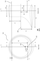
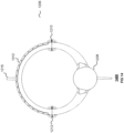
- FIG. 6 there are shown respective rear and median section views 600 of one embodiment of the vehicle 502.
- the embodiment of vehicle 502 has a centre of gravity 602, and an equilibrium centre of buoyancy 604 disposed directly above the centre of gravity 602 by a respective distance BZ.
- the free surface 106 is disposed, at equilibrium, above the X-Y plane by a distance FZ.
- the centre of gravity 602 is disposed behind the front of the vehicle by a distance FX.
- the hull of the embodiment of vehicle 502 comprises a surface of revolution about the axis 606, formed from a symmetrical aerofoil section of chord CU, with a distance between the chord line and the axis 606 of R.
- the hull comprises a lofted surface, commencing with the symmetrical aerofoil section of chord CU in the transverse plane, blending to a symmetrical aerofoil section of chord CL in the median plane, and returning to the symmetrical aerofoil section of chord CU in the transverse plane, with the chord line of the section following a half circle of radius R centred on the axis 606.
- the axis 606 is disposed above the centre of gravity 602 by a distance AZ.
- the aerofoil section used is a NACA0015 section, and the approximate mass of the vehicle is 53.4kg.
- the example makes good headway in regular waves of period 2.0s and amplitude 0.1m.
- the heaving and pitching of, in particular, the lower hull portion 506 of the vehicle 502 generates thrust.
- the thrust is associated with an unsteady wake such as, for example, a reverse von Kármán street of vortices, four of which vortices 710 to 716 are shown in FIG. 7 .
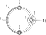
- FIG. 8 there is shown a front and top view 800 of the vehicle 502 in a beam sea, that is, interacting with a beam wave 806.
- the beam wave has a direction of travel that is perpendicular to the longitudinal axis of the vehicle 502 as indicated by the arrow 808.
- the beam wave when interacting with the vehicle 502 causes the vehicle to oscillate about a centre of gravity 810.
- the oscillation illustrated in FIG. 8 is a roll oscillation indicated by the arrow 812.
- the roll oscillation has a respective angular amplitude 814.
- the respective amplitude 814 is related to the incident wave 806.
- the oscillation results in forward thrust being generated.
- the forward thrust is indicated by the arrow 816.
- secondary oscillations (not shown) in or about any of the axes of the vehicle may occur concurrently with the roll oscillation illustrated, and that such secondary oscillations may enhance the thrust produced.
- the thrust is associated with an unsteady wake from at least one hydrofoil portion of the hull, such as, for example a reverse von Kármán street of vortices, two examples 818 and 820 of which are shown in FIG. 8 .
- the vehicle 908 is an example of the above-described vehicle 502.
- the vehicle 908 comprises one or more than one hydrodynamic control surface.
- the one or more than one hydrodynamic control surface is used to steer the vehicle while in motion.
- the vehicle 908 comprises a hydrodynamic control surface 912 that is disposed beneath, or forms part of, the lower hull portion 910 of the vehicle 908.
- a symmetrically disposed hydrodynamic control surface can be included within the cavity.
- Such an internally contained hydrodynamic control surface 914 is illustrated.
- the vehicle 908 may comprise a set of hydrodynamic control surfaces.
- the set of hydrodynamic control surfaces may comprise a pair of control surfaces 916 and 918 positioned on, or at, the trailing edge 920 of the lower hull portion 910 of the vehicle 908.
- control surfaces may be realised to steer the vehicle.
- the vehicle 1010 is an example of the above-described vehicle 502. It can be appreciated that the vehicle comprises a set of solar energy harvesting panels 1012.
- the set of solar energy harvesting panels 1012 can comprise a set of solar panels.
- the set of solar energy harvesting panels are disposed on the upper half of the vehicle 1010.
- the solar energy harvesting panels can comprise, for example, photovoltaic panels or cells.
- the vehicle 1010 may additionally comprise a set of hydrodynamic control surfaces. In the illustrated example, a pair 1014 and 1016 of hydrodynamic control surfaces is provided.
- the pair 1014 and 1016 of hydrodynamic control surfaces are substantially the same as the above-described pair 916 and 918 of hydrodynamic control surfaces.
- the vehicle 1010 can also comprise an internal hydrodynamic control surface 1018 comparable to the above-described hydrodynamic control surface 914.
- the set of solar energy harvesting panels 1012 is arranged to generate and store electricity from sunlight in a battery (not shown).
- the stored energy can be used to drive any onboard electrical or electronic systems of the vehicle 1010.
- the vehicle 1102 is an example of the above-described vehicle 502. It can be appreciated that the vehicle additionally comprises an empennage referred to generally by the reference numeral 1104.
- the empennage 1104 is arranged to allow the vehicle 1102 to be aerially launched from, for example, a large aeroplane.
- the vehicle given the empennage, can glide or fly a number of miles according to the altitude of launch.
- the empennage comprises a number of control surfaces and actuating mechanisms of a kind apparent to one skilled in the art (not shown) to control or otherwise steer the vehicle 1102 towards its destination during flight.
- any vehicle described herein can have such an associated empennage.
- the empennage 1104 may be ejected from the vehicle.
- providing an empennage supports an aerial gliding flight mode of operation.
- This mode of operation is desirable for rapid aerial deployment of one or more than one vehicle to a specific location or locations on the surface, for example, for the purposes of monitoring large scale features in oceanographic applications, or for rapidly assessing large areas in defence and security applications.
- the vehicle 1206 is an example of the above-described vehicle 502.
- the vehicle 1206 additionally comprises at least one, or both, of a pressure hull 1208 and one or more than one supplementary thruster.
- three supplementary thrusters 1210, 1212 and 1214 are provided.
- the one or more than one supplementary thruster represents a set of supplementary thrusters.
- the one or more than one thruster 1210-1214 can be powered by the above-described battery (not shown).
- the vehicle 1206 also comprises the above-described solar energy harvesting panels 1012, and a symmetrically disposed control surface 1218.
- the supplementary thrusters 1210-1214 can be used to at least one of drive, control or steer, taken jointly and severally in any and all permutations, the vehicle 1206, including when the vehicle is fully submerged, especially when sufficiently removed from the surface waves, the influence of which progressively decreases with depth from the surface.
- the thrusters 1210-1214 may be used to steer the direction of the vehicle 1206.
- the control surface 1218 may be used to steer the vehicle.
- hydrofoil portions of the vehicle's hull act as lifting surfaces in underwater powered or gliding flight.
- the control surface 1218 may be used to steer the vehicle.
- the pressurised hull 1208 forms part of a buoyancy control system, described with reference to FIG. 18 , which is used to influence the buoyancy of the vehicle 1206. Buoyancy is controlled to support the vehicle 1206 in diving and returning to the surface following such a dive.
- the vehicle 1206 also comprises an antenna or antennas 1216 to support communication.
- FIGs. 13 to 17 depict respective views of the vehicle 1206 shown in, and described with reference to, FIG. 12 .
- FIG. 13 depicts a side view 1300 of the vehicle 1206.
- FIG. 14 depicts a front view 1400 of the vehicle 1206.
- FIG. 15 depicts a rear view 1500 of the vehicle 1206.
- FIG. 16 depicts a top view 1600 of the vehicle 1206.
- FIG. 17 depicts a bottom view 1700 of the vehicle 1206.
- FIG. 18 there is shown a view 1800 of a buoyancy control system associated with any of the vehicles described herein and/or as shown in the figures.
- the view 1800 is a frontal crosssectional view of the hull of the vehicle 1206. It can be appreciated that the hull has been divided into a number of compartments 1802 to 1812.
- the following description refers to water as the fluid in which the vehicle floats, and air as the fluid above the free surface, but one skilled in the art will appreciate that the description can equally be applied to a range of fluid combinations.
- the upper-most compartment may contain water or air.
- water may be exchanged for air and vice-versa through a simple valve and pump (not shown).
- a pair of middle compartments 1804 and 1806 is provided to give buoyancy to the vehicle 1206.
- the compartments 1804 and 1806 can be filled with a foam such as, for example, a syntactic foam.
- the foam can have a density that is lower than that of water to provide positive buoyancy.
- a pair 1808 and 1810 of further compartments is provided.
- the compartments 1808 and 1810 are free-flooding compartments.
- the free-flooding compartments 1808 and 1810 may contain either water or a buoyancy control working fluid.
- the buoyancy control working fluid can comprise a mineral oil, or other liquid that is substantially incompressible and preferably less dense than water.
- the buoyancy control working fluid may be pumped into or out of a bladder 1814 to populate or evacuate corresponding bladders (not shown) in the compartments 1808 and 1810. When the buoyancy control working fluid is pumped into the bladder within each of the compartments 1808 and 1810, water within the compartments 1808 and 1810 is displaced into the ambient water surrounding the vehicle 1206.
- the lowest compartment 1812 is a pressure hull.
- the pressure hull 1812 is filled with air but for the bladder 1814, which is arranged to store a volume of buoyancy control working fluid.
- the buoyancy control working fluid stored in the bladder 1814 can be pumped into the bladders (not shown) within the compartments 1808 and 1810. Conversely, the buoyancy control working fluid may be evacuated from the bladders (not shown) within the compartments 1808 and 1810 into the storage bladder 1814.
- the upper compartment 1802 When the vehicle is operating at the surface, the upper compartment 1802 is filled with air, and the buoyancy control compartments 1808 and 1810 are filled with water.
- the vehicle 1206 is arranged to be positively buoyant in this condition.
- the upper compartment 1802 When the vehicle 1206 is required to dive, the upper compartment 1802 is filled with water, that is, the air is discharged and the vehicle 1206 becomes negatively buoyant.
- the negative buoyancy allows the vehicle 1206 to dive.
- the direction of travel during the dive can be controlled by the supplementary thrusters and/or hydrodynamic control surfaces.
- the buoyancy control working fluid stored within the storage bladder 1814 is pumped into the bladders within the buoyancy control compartments 1808 and 1810, which displaces any water within those compartments 1808 and 1810 into the surrounding environment.
- the resulting effect is that the vehicle 1206 becomes positively buoyant.
- the upper compartment 1802 can be filled with air by expelling the water it contains into the surrounding environment, which further increases the overall buoyancy of the vehicle 1206.
- the buoyancy control working fluid can then be pumped out of buoyancy control compartments 1808 and 1810 into the storage bladder 1814, which allows the buoyancy control compartments 1808 and 1810 to be filled with water again.
- buoyancy control system such as that described may act to alter at least one, or both, of: the centre of gravity position or mass of the vehicle. It will be appreciated that such an alteration may be used when the vehicle is at the surface to dynamically improve, preferably optimise, the vehicle's wave response dynamics to suit ambient waves, especially through the use of an air compartment such as the upper compartment 1802 in the example provided.
- control of at least one of the following taken jointly and severally in any and all permutations: the vertical position of the centre of gravity of the vehicle relative to the vertical position of the centre of buoyancy of the vehicle, the mass of the vehicle, inertia in the roll direction and inertia in the pitch direction, can be used to effectively tune the response of the vehicle, for example, in at least one, or both, of: pitch and roll.
- the mass and centre of buoyancy are related such that when the mass is increased, the vehicle becomes more submerged and the centre of buoyancy lowers, and vice versa.
- an alteration of the longitudinal or lateral position of the centre of gravity may be used to effect any combination of at least one or more than one of: lateral, longitudinal, and directional control when on the surface or when below the surface taken jointly and severally in any and all permutations.
- a buoyancy control system may be used to effect a centre of gravity alteration, for example, a mass shift system may be used to do so.
- the control system 1902 comprises a processor 1904 for controlling or otherwise orchestrating all of the control and operational functions associated with the vehicle.
- the position of a vehicle is determined using a GPS system 1906.
- the GPS system is arranged to provide position information to a navigation system 1908.
- the navigation system is arranged to make or execute operational actions or decisions according to desired actions of the vehicle. For example, the navigation system can influence a control surface system 1910.
- the control surface system 1910 is arranged to control the hydrodynamic control surfaces described above and/or any thrusters if present.
- the control system 1902 also comprises a sensor system 1912.
- the sensor system is arranged to monitor, for example, the depth or pressure of the environment of a vehicle.
- the sensor system 1912 can also be arranged to carry sensors for taking measurements or readings associated with the environment such as, for example, sonar sensors for performing sonar sensing such as, for example sonar imaging.
- the control system 1902 also comprises a buoyancy/dive control system 1914.
- the buoyancy/dive control system 1914 is arranged to control diving of the vehicle; that is, to control descent, depth maintenance and ascent operations in response to commands from the processor 1904.
- a power management system 1916 is provided to distribute power according to current operational demands of a vehicle and to control charging of a battery 1918 to harvest solar energy using the above-described solar energy harvesting panels.
- a communication system 1920 is also provided to manage communications with a command and control centre (not shown).
- the examples described herein can be deployed and left in theatre or on task for long durations since the movement is wave-powered. Being wave-powered allows the vehicles to autonomously perform a task on site and then drift to a collection point or base under wave-power. Any example vehicle described herein can be arranged to dive and operate beneath the thermocline of a body of fluid.
- Example vehicles described and/or claims herein can provide a single form to efficiently perform both the wave-response and thrust-production functions whilst reducing or eliminating the need for moving parts, increasing simplicity and robustness, and generally improving performance relative to the prior art.
Landscapes
- Engineering & Computer Science (AREA)
- Mechanical Engineering (AREA)
- Physics & Mathematics (AREA)
- Fluid Mechanics (AREA)
- Aviation & Aerospace Engineering (AREA)
- Chemical & Material Sciences (AREA)
- Combustion & Propulsion (AREA)
- Ocean & Marine Engineering (AREA)
- Other Liquid Machine Or Engine Such As Wave Power Use (AREA)
Claims (15)
- Wellenangetriebenes Fahrzeug (102), das konfiguriert ist, um auf der freien Oberfläche (106) eines Fluidkörpers zu schwimmen, das Fahrzeug umfassend einen Rumpf (104); der Rumpf umfassendeinen oberen Rumpfabschnitt (118), umfassend mindestens einen Tragflächenabschnitt (128), wobei der obere Rumpfabschnitt den Abschnitt des Rumpfs umfasst, der durch eine obere Erstreckung 114 und eine untere Erstreckung 116 des "dynamischen Eintauchens" des Rumpfs definiert ist und daher angeordnet ist, um unter der Wirkung von Oberflächenwellen des Fluidkörpers periodisch durch die freie Oberfläche des Fluidkörpers einzutauchen und durch die Ebene der freien Oberfläche (106) des Fluidkörpers im Gleichgewicht geteilt zu werden, undeinen unteren Rumpfabschnitt (120), der als der Abschnitt des Rumpfs unterhalb der unteren Erstreckung 116 eines dynamischen Eintauchens definiert ist, umfassend eine Tragflächenstruktur (130), umfassend mindestens einen Tragflächenabschnitt, wobei die Tragflächenstruktur im Wesentlichen nicht planar ist und betrachtet von der Vorderseite oder der Rückseite des Fahrzeugs aus eine vertikal gerichtete Konkavität bereitstellt;wobei mindestens eines oder beide von Folgenden gilt:a) die Tragflächenstruktur (130) des unteren Rumpfabschnitts (120) ist im Wesentlichen starr; undb) ein oder mehr als ein Tragflächenabschnitt des mindestens einen Tragflächenabschnitts (128) des oberen Rumpfabschnitts bildet einen Großteil des Volumens des oberen Rumpfabschnitts (118).
- Fahrzeug nach einem der vorhergehenden Ansprüche, wobei die Tragflächenstruktur des unteren Rumpfabschnitts in einer im Wesentlichen starren Anordnung in Bezug auf das Fahrzeug gehalten wird, sodass die Gesamtbewegung des Fahrzeugs und die Bewegung der Tragflächenstruktur im Wesentlichen direkt gekoppelt sind.
- Fahrzeug nach einem der vorhergehenden Ansprüche, wobei mindestens ein Tragflächenabschnitt des oberen Rumpfabschnitts mindestens eine vertikale Erstreckung aufweist.
- Fahrzeug nach einem der vorhergehenden Ansprüche, wobei der Längsschwerpunkt des Fahrzeugs näher an der Vorderseite des Fahrzeugs ist als an der Rückseite des Fahrzeugs.
- Fahrzeug nach einem der vorhergehenden Ansprüche, wobei der Volumenschwerpunkt des oberen Rumpfabschnitts vor dem Längsschwerpunkt des Fahrzeugs positioniert ist.
- Fahrzeug nach einem der vorhergehenden Ansprüche, wobei der Schwerpunkt, wenn das Fahrzeug in ruhigem Fluid ist, über der Auftriebsmitte angeordnet ist.
- Fahrzeug nach einem der vorhergehenden Ansprüche, wobei der Rumpf auf ein Leistungsspektrum von Wellen reagiert, umfassend eine Komponente, die im Wesentlichen bei einer oder mehreren von Folgenden ist: der natürlichen Hebe-, Roll- und Nickfrequenz des Fahrzeugs, gemeinsam genommen und einzeln in beliebigen und allen Permutationen betrachtet.
- Fahrzeug nach einem der vorhergehenden Ansprüche, wobei der Rumpf, wenn das Fahrzeug in ruhigem Fluid ist, einen in Längsrichtung ausgerichteten, nach oben weisenden Kanal definiert.
- Fahrzeug nach Anspruch 8, wobei der Kanal im Wesentlichen durch einen oder mehrere Tragflächenabschnitte gebildet ist, die angeordnet sind, um als Begrenzung des Kanals zu wirken.
- Fahrzeug nach Anspruch 9, wobei sich mindestens eine Tragflächenabschnittsbegrenzung des Kanals oberhalb der freien Oberfläche erstreckt.
- Fahrzeug nach einem der vorhergehenden Ansprüche, wobei der Rumpf von der Vorderseite oder der Rückseite des Fahrzeugs aus betrachtet einen im Wesentlichen starren, stromlinienförmigen Körper umfasst, umfassend eine in Längsrichtung ausgerichtete Röhre geschlossener Form.
- Fahrzeug nach Anspruch 11, wobei die geschlossene Form der Röhre teilweise oder vollständig mindestens eines von Folgenden ist: elliptisch oder kreisförmig, optional wobei die geschlossene Form der Röhre teilweise oder vollständig polygonal ist, optional mit abgerundeten Ecken.
- Fahrzeug nach einem der vorhergehenden Ansprüche, umfassend ein parametervariierendes System, um einen Parameter des Fahrzeugs, wie beispielsweise die Masse oder die Schwerpunktposition des Fahrzeugs, zu variieren, während das Fahrzeug in Betrieb ist.
- Fahrzeug nach Anspruch 13, wobei das parametervariierende System ein Auftriebssteuersystem umfasst, optional wobei das Auftriebssteuersystem zu mindestens einem oder beiden von Folgenden angeordnet ist: Ändern des Verhältnisses der Masse des Fahrzeugs zu der Masse des von dem Fahrzeug verdrängten Fluids und Bewirken, dass das Fahrzeug durch die Fluidsäule absteigt bzw. aufsteigt, vorzugsweise wobei eine Tragflächenstruktur des Fahrzeugs als Reaktion auf eine vertikale Bewegung des Fahrzeugs durch die Fluidsäule aufgrund des Betriebs des Auftriebssteuersystems einen Vorwärtsschub erzeugt, was bewirkt, dass das Fahrzeug vorwärts gleitet.
- Fahrzeug nach einem der vorhergehenden Ansprüche, ferner umfassend mindestens eines oder mehr als eines der Folgenden in beliebigen und allen Kombinationen:eine Bedienoberfläche,ein Triebwerk,eine Sonnenenergiegewinnungsvorrichtung,ein Leitwerk, undein Lenksystem, das auf ein Leitsystem reagiert, um das Fahrzeug zu lenken.
Applications Claiming Priority (2)
| Application Number | Priority Date | Filing Date | Title |
|---|---|---|---|
| GB2116187.2A GB2612792B (en) | 2021-11-10 | 2021-11-10 | Wave-propelled vehicles |
| PCT/GB2022/052859 WO2023084228A1 (en) | 2021-11-10 | 2022-11-10 | Wave-propelled vehicles |
Publications (3)
| Publication Number | Publication Date |
|---|---|
| EP4429945A1 EP4429945A1 (de) | 2024-09-18 |
| EP4429945B1 true EP4429945B1 (de) | 2025-05-14 |
| EP4429945C0 EP4429945C0 (de) | 2025-05-14 |
Family
ID=79171178
Family Applications (1)
| Application Number | Title | Priority Date | Filing Date |
|---|---|---|---|
| EP22802700.9A Active EP4429945B1 (de) | 2021-11-10 | 2022-11-10 | Wellenangetriebene fahrzeuge |
Country Status (6)
| Country | Link |
|---|---|
| US (1) | US20250002117A1 (de) |
| EP (1) | EP4429945B1 (de) |
| AU (1) | AU2022384735A1 (de) |
| CA (1) | CA3237970A1 (de) |
| GB (1) | GB2612792B (de) |
| WO (1) | WO2023084228A1 (de) |
Family Cites Families (4)
| Publication number | Priority date | Publication date | Assignee | Title |
|---|---|---|---|---|
| WO1980001674A1 (fr) * | 1979-02-09 | 1980-08-21 | E Hartmann | Dispositif pour l'exploitation de l'energie des vagues des lacs et des mers |
| US7371136B2 (en) | 2006-01-20 | 2008-05-13 | Liquid Robotics Inc. | Wave power |
| GB2503916B (en) | 2012-07-12 | 2014-12-17 | Eco Nomic Ltd | A wave powered water-borne vessel |
| GB201514901D0 (en) * | 2015-08-21 | 2015-10-07 | Cetus Technology Ltd | Device for linear propulsion |
-
2021
- 2021-11-10 GB GB2116187.2A patent/GB2612792B/en active Active
-
2022
- 2022-11-10 WO PCT/GB2022/052859 patent/WO2023084228A1/en not_active Ceased
- 2022-11-10 US US18/709,096 patent/US20250002117A1/en active Pending
- 2022-11-10 EP EP22802700.9A patent/EP4429945B1/de active Active
- 2022-11-10 CA CA3237970A patent/CA3237970A1/en active Pending
- 2022-11-10 AU AU2022384735A patent/AU2022384735A1/en active Pending
Also Published As
| Publication number | Publication date |
|---|---|
| EP4429945A1 (de) | 2024-09-18 |
| GB2612792B (en) | 2024-06-12 |
| GB2612792A (en) | 2023-05-17 |
| CA3237970A1 (en) | 2023-05-19 |
| WO2023084228A1 (en) | 2023-05-19 |
| AU2022384735A1 (en) | 2024-06-27 |
| EP4429945C0 (de) | 2025-05-14 |
| US20250002117A1 (en) | 2025-01-02 |
Similar Documents
| Publication | Publication Date | Title |
|---|---|---|
| CN100532192C (zh) | 混合型水下航行器 | |
| EP2078671B1 (de) | Tauchfahrzeug | |
| JP5504499B2 (ja) | ソーラー水中グライダー及びその潜航方法 | |
| US7029340B2 (en) | Regenerative surfing | |
| KR102168122B1 (ko) | 무인선 에너지 확보를 위한 파력 추진 복합 소출력 발전 시스템 | |
| Jenkins et al. | Autonomous underwater gliders | |
| CN106741584A (zh) | 升力型高速海洋机器人 | |
| US12110085B2 (en) | Underwater glider | |
| CA1048894A (en) | Apparatus for use in the extraction of energy from waves on water | |
| Mannam et al. | Experimental and numerical study of penguin mode flapping foil propulsion system for ships | |
| Patil et al. | Design optimization of an AUV for performing depth control maneuver | |
| CN116872661B (zh) | 一种海洋航行器 | |
| CN114435044A (zh) | 一种可变体的跨介质航行器 | |
| CN117002706A (zh) | 一种水面水下航行器及其航行控制方法 | |
| AU2012203854B2 (en) | Submersible Vehicle | |
| Rozhdestvensky et al. | Recent advances in hydrodynamics of wing propulsive lifting systems for ships and underwater vehicles | |
| Aage et al. | Hydrodynamic manoeuvrability data of a flatfish type AUV | |
| Elkolali et al. | A low-cost wave/solar powered unmanned surface vehicle | |
| Khalin et al. | Performance comparison of different aerodynamic shapes for autonomous underwater vehicles | |
| EP4429945B1 (de) | Wellenangetriebene fahrzeuge | |
| Spino et al. | Development and testing of unmanned semi-submersible vehicle | |
| CN110040230B (zh) | 一种将波浪能转换成低频纵摇运动实现推进的海洋运载器 | |
| US11110995B2 (en) | Surface vessel with motorised mechanical propulsion having a fusiform hull and ballasted keel | |
| Zhi et al. | A hybrid underwater profiler with thrusters used for fixed-point ocean observation | |
| CN219707300U (zh) | 一种利用波浪能的自主水上航行器 |
Legal Events
| Date | Code | Title | Description |
|---|---|---|---|
| STAA | Information on the status of an ep patent application or granted ep patent |
Free format text: STATUS: UNKNOWN |
|
| STAA | Information on the status of an ep patent application or granted ep patent |
Free format text: STATUS: THE INTERNATIONAL PUBLICATION HAS BEEN MADE |
|
| PUAI | Public reference made under article 153(3) epc to a published international application that has entered the european phase |
Free format text: ORIGINAL CODE: 0009012 |
|
| STAA | Information on the status of an ep patent application or granted ep patent |
Free format text: STATUS: REQUEST FOR EXAMINATION WAS MADE |
|
| 17P | Request for examination filed |
Effective date: 20240610 |
|
| AK | Designated contracting states |
Kind code of ref document: A1 Designated state(s): AL AT BE BG CH CY CZ DE DK EE ES FI FR GB GR HR HU IE IS IT LI LT LU LV MC ME MK MT NL NO PL PT RO RS SE SI SK SM TR |
|
| GRAP | Despatch of communication of intention to grant a patent |
Free format text: ORIGINAL CODE: EPIDOSNIGR1 |
|
| STAA | Information on the status of an ep patent application or granted ep patent |
Free format text: STATUS: GRANT OF PATENT IS INTENDED |
|
| DAV | Request for validation of the european patent (deleted) | ||
| DAX | Request for extension of the european patent (deleted) | ||
| INTG | Intention to grant announced |
Effective date: 20241203 |
|
| GRAS | Grant fee paid |
Free format text: ORIGINAL CODE: EPIDOSNIGR3 |
|
| GRAA | (expected) grant |
Free format text: ORIGINAL CODE: 0009210 |
|
| STAA | Information on the status of an ep patent application or granted ep patent |
Free format text: STATUS: THE PATENT HAS BEEN GRANTED |
|
| AK | Designated contracting states |
Kind code of ref document: B1 Designated state(s): AL AT BE BG CH CY CZ DE DK EE ES FI FR GB GR HR HU IE IS IT LI LT LU LV MC ME MK MT NL NO PL PT RO RS SE SI SK SM TR |
|
| REG | Reference to a national code |
Ref country code: GB Ref legal event code: FG4D |
|
| REG | Reference to a national code |
Ref country code: CH Ref legal event code: EP |
|
| REG | Reference to a national code |
Ref country code: DE Ref legal event code: R096 Ref document number: 602022014764 Country of ref document: DE |
|
| REG | Reference to a national code |
Ref country code: IE Ref legal event code: FG4D |
|
| U01 | Request for unitary effect filed |
Effective date: 20250612 |
|
| U07 | Unitary effect registered |
Designated state(s): AT BE BG DE DK EE FI FR IT LT LU LV MT NL PT RO SE SI Effective date: 20250623 |
|
| PG25 | Lapsed in a contracting state [announced via postgrant information from national office to epo] |
Ref country code: ES Free format text: LAPSE BECAUSE OF FAILURE TO SUBMIT A TRANSLATION OF THE DESCRIPTION OR TO PAY THE FEE WITHIN THE PRESCRIBED TIME-LIMIT Effective date: 20250514 |
|
| PG25 | Lapsed in a contracting state [announced via postgrant information from national office to epo] |
Ref country code: GR Free format text: LAPSE BECAUSE OF FAILURE TO SUBMIT A TRANSLATION OF THE DESCRIPTION OR TO PAY THE FEE WITHIN THE PRESCRIBED TIME-LIMIT Effective date: 20250815 |
|
| PG25 | Lapsed in a contracting state [announced via postgrant information from national office to epo] |
Ref country code: PL Free format text: LAPSE BECAUSE OF FAILURE TO SUBMIT A TRANSLATION OF THE DESCRIPTION OR TO PAY THE FEE WITHIN THE PRESCRIBED TIME-LIMIT Effective date: 20250514 |
|
| PG25 | Lapsed in a contracting state [announced via postgrant information from national office to epo] |
Ref country code: HR Free format text: LAPSE BECAUSE OF FAILURE TO SUBMIT A TRANSLATION OF THE DESCRIPTION OR TO PAY THE FEE WITHIN THE PRESCRIBED TIME-LIMIT Effective date: 20250514 |
|
| PG25 | Lapsed in a contracting state [announced via postgrant information from national office to epo] |
Ref country code: RS Free format text: LAPSE BECAUSE OF FAILURE TO SUBMIT A TRANSLATION OF THE DESCRIPTION OR TO PAY THE FEE WITHIN THE PRESCRIBED TIME-LIMIT Effective date: 20250814 |
|
| PG25 | Lapsed in a contracting state [announced via postgrant information from national office to epo] |
Ref country code: IS Free format text: LAPSE BECAUSE OF FAILURE TO SUBMIT A TRANSLATION OF THE DESCRIPTION OR TO PAY THE FEE WITHIN THE PRESCRIBED TIME-LIMIT Effective date: 20250914 |