EP4429601B1 - Orthopädische implantatsysteme mit fixierungselementen - Google Patents
Orthopädische implantatsysteme mit fixierungselementen Download PDFInfo
- Publication number
- EP4429601B1 EP4429601B1 EP23762067.9A EP23762067A EP4429601B1 EP 4429601 B1 EP4429601 B1 EP 4429601B1 EP 23762067 A EP23762067 A EP 23762067A EP 4429601 B1 EP4429601 B1 EP 4429601B1
- Authority
- EP
- European Patent Office
- Prior art keywords
- bore
- face
- mounting
- head
- flange
- Prior art date
- Legal status (The legal status is an assumption and is not a legal conclusion. Google has not performed a legal analysis and makes no representation as to the accuracy of the status listed.)
- Active
Links
Images


Classifications
-
- A—HUMAN NECESSITIES
- A61—MEDICAL OR VETERINARY SCIENCE; HYGIENE
- A61F—FILTERS IMPLANTABLE INTO BLOOD VESSELS; PROSTHESES; DEVICES PROVIDING PATENCY TO, OR PREVENTING COLLAPSING OF, TUBULAR STRUCTURES OF THE BODY, e.g. STENTS; ORTHOPAEDIC, NURSING OR CONTRACEPTIVE DEVICES; FOMENTATION; TREATMENT OR PROTECTION OF EYES OR EARS; BANDAGES, DRESSINGS OR ABSORBENT PADS; FIRST-AID KITS
- A61F2/00—Filters implantable into blood vessels; Prostheses, i.e. artificial substitutes or replacements for parts of the body; Appliances for connecting them with the body; Devices providing patency to, or preventing collapsing of, tubular structures of the body, e.g. stents
- A61F2/02—Prostheses implantable into the body
- A61F2/30—Joints
- A61F2/30721—Accessories
- A61F2/30749—Fixation appliances for connecting prostheses to the body
-
- A—HUMAN NECESSITIES
- A61—MEDICAL OR VETERINARY SCIENCE; HYGIENE
- A61F—FILTERS IMPLANTABLE INTO BLOOD VESSELS; PROSTHESES; DEVICES PROVIDING PATENCY TO, OR PREVENTING COLLAPSING OF, TUBULAR STRUCTURES OF THE BODY, e.g. STENTS; ORTHOPAEDIC, NURSING OR CONTRACEPTIVE DEVICES; FOMENTATION; TREATMENT OR PROTECTION OF EYES OR EARS; BANDAGES, DRESSINGS OR ABSORBENT PADS; FIRST-AID KITS
- A61F2/00—Filters implantable into blood vessels; Prostheses, i.e. artificial substitutes or replacements for parts of the body; Appliances for connecting them with the body; Devices providing patency to, or preventing collapsing of, tubular structures of the body, e.g. stents
- A61F2/02—Prostheses implantable into the body
- A61F2/30—Joints
- A61F2/30721—Accessories
- A61F2/30734—Modular inserts, sleeves or augments, e.g. placed on proximal part of stem for fixation purposes or wedges for bridging a bone defect
-
- A—HUMAN NECESSITIES
- A61—MEDICAL OR VETERINARY SCIENCE; HYGIENE
- A61F—FILTERS IMPLANTABLE INTO BLOOD VESSELS; PROSTHESES; DEVICES PROVIDING PATENCY TO, OR PREVENTING COLLAPSING OF, TUBULAR STRUCTURES OF THE BODY, e.g. STENTS; ORTHOPAEDIC, NURSING OR CONTRACEPTIVE DEVICES; FOMENTATION; TREATMENT OR PROTECTION OF EYES OR EARS; BANDAGES, DRESSINGS OR ABSORBENT PADS; FIRST-AID KITS
- A61F2/00—Filters implantable into blood vessels; Prostheses, i.e. artificial substitutes or replacements for parts of the body; Appliances for connecting them with the body; Devices providing patency to, or preventing collapsing of, tubular structures of the body, e.g. stents
- A61F2/02—Prostheses implantable into the body
- A61F2/30—Joints
- A61F2/40—Joints for shoulders
- A61F2/4014—Humeral heads or necks; Connections of endoprosthetic heads or necks to endoprosthetic humeral shafts
-
- A—HUMAN NECESSITIES
- A61—MEDICAL OR VETERINARY SCIENCE; HYGIENE
- A61B—DIAGNOSIS; SURGERY; IDENTIFICATION
- A61B17/00—Surgical instruments, devices or methods
- A61B17/56—Surgical instruments or methods for treatment of bones or joints; Devices specially adapted therefor
- A61B17/58—Surgical instruments or methods for treatment of bones or joints; Devices specially adapted therefor for osteosynthesis, e.g. bone plates, screws or setting implements
- A61B17/68—Internal fixation devices, including fasteners and spinal fixators, even if a part thereof projects from the skin
- A61B17/72—Intramedullary devices, e.g. pins or nails
-
- A—HUMAN NECESSITIES
- A61—MEDICAL OR VETERINARY SCIENCE; HYGIENE
- A61F—FILTERS IMPLANTABLE INTO BLOOD VESSELS; PROSTHESES; DEVICES PROVIDING PATENCY TO, OR PREVENTING COLLAPSING OF, TUBULAR STRUCTURES OF THE BODY, e.g. STENTS; ORTHOPAEDIC, NURSING OR CONTRACEPTIVE DEVICES; FOMENTATION; TREATMENT OR PROTECTION OF EYES OR EARS; BANDAGES, DRESSINGS OR ABSORBENT PADS; FIRST-AID KITS
- A61F2/00—Filters implantable into blood vessels; Prostheses, i.e. artificial substitutes or replacements for parts of the body; Appliances for connecting them with the body; Devices providing patency to, or preventing collapsing of, tubular structures of the body, e.g. stents
- A61F2/02—Prostheses implantable into the body
- A61F2/30—Joints
- A61F2/40—Joints for shoulders
- A61F2/4059—Humeral shafts
-
- A—HUMAN NECESSITIES
- A61—MEDICAL OR VETERINARY SCIENCE; HYGIENE
- A61F—FILTERS IMPLANTABLE INTO BLOOD VESSELS; PROSTHESES; DEVICES PROVIDING PATENCY TO, OR PREVENTING COLLAPSING OF, TUBULAR STRUCTURES OF THE BODY, e.g. STENTS; ORTHOPAEDIC, NURSING OR CONTRACEPTIVE DEVICES; FOMENTATION; TREATMENT OR PROTECTION OF EYES OR EARS; BANDAGES, DRESSINGS OR ABSORBENT PADS; FIRST-AID KITS
- A61F2/00—Filters implantable into blood vessels; Prostheses, i.e. artificial substitutes or replacements for parts of the body; Appliances for connecting them with the body; Devices providing patency to, or preventing collapsing of, tubular structures of the body, e.g. stents
- A61F2/02—Prostheses implantable into the body
- A61F2/30—Joints
- A61F2002/30001—Additional features of subject-matter classified in A61F2/28, A61F2/30 and subgroups thereof
- A61F2002/30316—The prosthesis having different structural features at different locations within the same prosthesis; Connections between prosthetic parts; Special structural features of bone or joint prostheses not otherwise provided for
- A61F2002/30329—Connections or couplings between prosthetic parts, e.g. between modular parts; Connecting elements
- A61F2002/30331—Connections or couplings between prosthetic parts, e.g. between modular parts; Connecting elements made by longitudinally pushing a protrusion into a complementarily-shaped recess, e.g. held by friction fit
- A61F2002/30332—Conically- or frustoconically-shaped protrusion and recess
-
- A—HUMAN NECESSITIES
- A61—MEDICAL OR VETERINARY SCIENCE; HYGIENE
- A61F—FILTERS IMPLANTABLE INTO BLOOD VESSELS; PROSTHESES; DEVICES PROVIDING PATENCY TO, OR PREVENTING COLLAPSING OF, TUBULAR STRUCTURES OF THE BODY, e.g. STENTS; ORTHOPAEDIC, NURSING OR CONTRACEPTIVE DEVICES; FOMENTATION; TREATMENT OR PROTECTION OF EYES OR EARS; BANDAGES, DRESSINGS OR ABSORBENT PADS; FIRST-AID KITS
- A61F2/00—Filters implantable into blood vessels; Prostheses, i.e. artificial substitutes or replacements for parts of the body; Appliances for connecting them with the body; Devices providing patency to, or preventing collapsing of, tubular structures of the body, e.g. stents
- A61F2/02—Prostheses implantable into the body
- A61F2/30—Joints
- A61F2002/30001—Additional features of subject-matter classified in A61F2/28, A61F2/30 and subgroups thereof
- A61F2002/30316—The prosthesis having different structural features at different locations within the same prosthesis; Connections between prosthetic parts; Special structural features of bone or joint prostheses not otherwise provided for
- A61F2002/30329—Connections or couplings between prosthetic parts, e.g. between modular parts; Connecting elements
- A61F2002/30383—Connections or couplings between prosthetic parts, e.g. between modular parts; Connecting elements made by laterally inserting a protrusion, e.g. a rib into a complementarily-shaped groove
-
- A—HUMAN NECESSITIES
- A61—MEDICAL OR VETERINARY SCIENCE; HYGIENE
- A61F—FILTERS IMPLANTABLE INTO BLOOD VESSELS; PROSTHESES; DEVICES PROVIDING PATENCY TO, OR PREVENTING COLLAPSING OF, TUBULAR STRUCTURES OF THE BODY, e.g. STENTS; ORTHOPAEDIC, NURSING OR CONTRACEPTIVE DEVICES; FOMENTATION; TREATMENT OR PROTECTION OF EYES OR EARS; BANDAGES, DRESSINGS OR ABSORBENT PADS; FIRST-AID KITS
- A61F2/00—Filters implantable into blood vessels; Prostheses, i.e. artificial substitutes or replacements for parts of the body; Appliances for connecting them with the body; Devices providing patency to, or preventing collapsing of, tubular structures of the body, e.g. stents
- A61F2/02—Prostheses implantable into the body
- A61F2/30—Joints
- A61F2002/30001—Additional features of subject-matter classified in A61F2/28, A61F2/30 and subgroups thereof
- A61F2002/30316—The prosthesis having different structural features at different locations within the same prosthesis; Connections between prosthetic parts; Special structural features of bone or joint prostheses not otherwise provided for
- A61F2002/30329—Connections or couplings between prosthetic parts, e.g. between modular parts; Connecting elements
- A61F2002/30433—Connections or couplings between prosthetic parts, e.g. between modular parts; Connecting elements using additional screws, bolts, dowels, rivets or washers e.g. connecting screws
-
- A—HUMAN NECESSITIES
- A61—MEDICAL OR VETERINARY SCIENCE; HYGIENE
- A61F—FILTERS IMPLANTABLE INTO BLOOD VESSELS; PROSTHESES; DEVICES PROVIDING PATENCY TO, OR PREVENTING COLLAPSING OF, TUBULAR STRUCTURES OF THE BODY, e.g. STENTS; ORTHOPAEDIC, NURSING OR CONTRACEPTIVE DEVICES; FOMENTATION; TREATMENT OR PROTECTION OF EYES OR EARS; BANDAGES, DRESSINGS OR ABSORBENT PADS; FIRST-AID KITS
- A61F2/00—Filters implantable into blood vessels; Prostheses, i.e. artificial substitutes or replacements for parts of the body; Appliances for connecting them with the body; Devices providing patency to, or preventing collapsing of, tubular structures of the body, e.g. stents
- A61F2/02—Prostheses implantable into the body
- A61F2/30—Joints
- A61F2002/30001—Additional features of subject-matter classified in A61F2/28, A61F2/30 and subgroups thereof
- A61F2002/30316—The prosthesis having different structural features at different locations within the same prosthesis; Connections between prosthetic parts; Special structural features of bone or joint prostheses not otherwise provided for
- A61F2002/30535—Special structural features of bone or joint prostheses not otherwise provided for
- A61F2002/30604—Special structural features of bone or joint prostheses not otherwise provided for modular
- A61F2002/30616—Sets comprising a plurality of prosthetic parts of different sizes or orientations
-
- A—HUMAN NECESSITIES
- A61—MEDICAL OR VETERINARY SCIENCE; HYGIENE
- A61F—FILTERS IMPLANTABLE INTO BLOOD VESSELS; PROSTHESES; DEVICES PROVIDING PATENCY TO, OR PREVENTING COLLAPSING OF, TUBULAR STRUCTURES OF THE BODY, e.g. STENTS; ORTHOPAEDIC, NURSING OR CONTRACEPTIVE DEVICES; FOMENTATION; TREATMENT OR PROTECTION OF EYES OR EARS; BANDAGES, DRESSINGS OR ABSORBENT PADS; FIRST-AID KITS
- A61F2/00—Filters implantable into blood vessels; Prostheses, i.e. artificial substitutes or replacements for parts of the body; Appliances for connecting them with the body; Devices providing patency to, or preventing collapsing of, tubular structures of the body, e.g. stents
- A61F2/02—Prostheses implantable into the body
- A61F2/30—Joints
- A61F2/40—Joints for shoulders
- A61F2/4014—Humeral heads or necks; Connections of endoprosthetic heads or necks to endoprosthetic humeral shafts
- A61F2002/4029—Necks
-
- A—HUMAN NECESSITIES
- A61—MEDICAL OR VETERINARY SCIENCE; HYGIENE
- A61F—FILTERS IMPLANTABLE INTO BLOOD VESSELS; PROSTHESES; DEVICES PROVIDING PATENCY TO, OR PREVENTING COLLAPSING OF, TUBULAR STRUCTURES OF THE BODY, e.g. STENTS; ORTHOPAEDIC, NURSING OR CONTRACEPTIVE DEVICES; FOMENTATION; TREATMENT OR PROTECTION OF EYES OR EARS; BANDAGES, DRESSINGS OR ABSORBENT PADS; FIRST-AID KITS
- A61F2/00—Filters implantable into blood vessels; Prostheses, i.e. artificial substitutes or replacements for parts of the body; Appliances for connecting them with the body; Devices providing patency to, or preventing collapsing of, tubular structures of the body, e.g. stents
- A61F2/02—Prostheses implantable into the body
- A61F2/30—Joints
- A61F2/40—Joints for shoulders
- A61F2/4014—Humeral heads or necks; Connections of endoprosthetic heads or necks to endoprosthetic humeral shafts
- A61F2002/4037—Connections of heads to necks
-
- A—HUMAN NECESSITIES
- A61—MEDICAL OR VETERINARY SCIENCE; HYGIENE
- A61F—FILTERS IMPLANTABLE INTO BLOOD VESSELS; PROSTHESES; DEVICES PROVIDING PATENCY TO, OR PREVENTING COLLAPSING OF, TUBULAR STRUCTURES OF THE BODY, e.g. STENTS; ORTHOPAEDIC, NURSING OR CONTRACEPTIVE DEVICES; FOMENTATION; TREATMENT OR PROTECTION OF EYES OR EARS; BANDAGES, DRESSINGS OR ABSORBENT PADS; FIRST-AID KITS
- A61F2/00—Filters implantable into blood vessels; Prostheses, i.e. artificial substitutes or replacements for parts of the body; Appliances for connecting them with the body; Devices providing patency to, or preventing collapsing of, tubular structures of the body, e.g. stents
- A61F2/02—Prostheses implantable into the body
- A61F2/30—Joints
- A61F2/40—Joints for shoulders
- A61F2/4014—Humeral heads or necks; Connections of endoprosthetic heads or necks to endoprosthetic humeral shafts
- A61F2002/4044—Connections of necks to shafts
Definitions
- This disclosure relates to orthopaedic procedures and, more particularly, to orthopaedic implant systems and methods for repairing bone defects and restoring functionality to a joint.
- US 6 228 120 B1 discloses surgical equipment for implanting a total shoulder prosthesis, and total shoulder prosthesis constituting same.
- EP 0 679 375 A1 discloses a modular prosthetic assembly for the shoulder joint.
- WO 03/005933 A2 discloses shoulder prosthesis.
- DE 299 18 589 U1 discloses an endoprosthesis for a shoulder joint.
- WO 2015/103313 A1 discloses instruments and techniques for orienting prosthesis components for joint prostheses.
- the implant systems may include one or more fixation features for securing components of the implant systems to each other and/or adjacent tissue of a patient.
- the fixation features may include a taper locking mechanism to limit or otherwise oppose separation between components.
- the fixation features may include one or more flanges adapted to abut an exterior of the bone. The flange may be releasably securable to another component of the implant system and may be securable with one or more flexible constructs.
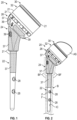
- An orthopaedic implant system of the present disclosure may include a stem portion insertable into bone and a mounting portion extending from the stem portion.
- the mounting portion may include a first mounting bore extending inwardly from a first engagement face and a raised protrusion extending outwardly from the first engagement face.
- the raised protrusion may taper along a declined face toward the first engagement face.
- a head portion may be adapted to mount an articulation member.
- the head portion may include a head bore extending inwardly from a second engagement face and a recess extending inwardly from the second engagement face.
- a periphery of the recess may include an inclined face sloping towards an opening of the recess along the second engagement face.
- a method of installing an orthopaedic implant system of the present disclosure may include inserting a stem portion into bone.
- a mounting portion may be coupled to the stem portion.
- the mounting portion may include a raised protrusion having a declined face.
- the method may include coupling a head portion to the mounting portion, which may include positioning the raised protrusion in a recess of the head portion and may include securing a fastener between the head portion and the mounting portion to cause the head portion to move across the mounting portion to compress an inclined face of the recess against the declined face of the raised protrusion.
- An orthopaedic implant system of the present disclosure may include a head portion adapted to mount an articulation member.
- the articulation member may be configured to mate with an opposed articular surface.
- a stem portion may be insertable into bone.
- a collar portion may be adapted to interconnect the head portion and the stem portion.
- a flange portion may be releasably securable to the collar portion.
- the flange portion may include a flange body and at least one engagement flange that may be dimensioned to abut bone.
- the collar portion may include a channel dimensioned to at least partially receive the flange body.
- the flange portion may be moveable in a direction towards the collar portion to trap a portion of bone between the at least one engagement flange and the stem portion in response to fixing a length of a flexible construct that may couple the collar portion and the flange portion in an installed position.
- a method of installing an orthopaedic implant system of the present disclosure may include inserting a stem portion into an intramedullary canal of a bone.
- the method may include inserting at least one interface flange of a flange portion into a channel of a collar portion.
- the collar portion may interconnect the stem portion and a head portion.
- the head portion may be adapted to mount an articulation member.
- the flange portion may include at least one engagement flange.
- the method may include trapping a wall of the bone between the stem portion and the at least one engagement flange in response to fixing a length of a flexible construct coupling the collar portion and the flange portion.
- the present disclosure may include any one or more of the individual features disclosed above and/or below alone or in any combination thereof.
- the disclosed implant systems described herein may include a modular prosthesis that may be adapted to facilitate reconstruction or repair of a long bone that may be caused by trauma to the patient.
- the long bone may have relatively severe proximal bone loss due to fracturing (e.g., 3 part or 4 part fractures) or shattering of the bone due to trauma, or a tumor in the bone, for example.
- Bone loss may be on the order of approximately one-third of the bone that may indicate a reconstruction procedure.
- the disclosed implant systems and methods may be utilized to restore functionality to a shoulder joint, including anatomical and reverse shoulder procedures.
- the disclosed implant systems described herein may include a taper locking mechanism to secure adjacent portions of the implant system together in an installed position, such as a head portion and mounting portion of the implant system.
- the head portion may be adapted to mount an articulation member for mating with an opposed articular surface of a joint.
- the mounting portion may be coupled to a stem portion insertable into the humerus or other long bone.
- the taper locking mechanism may be adapted to limit or otherwise oppose separation between the head portion and mounting portion, which may improve healing of the patient.
- the disclosed implant systems may include a flange portion securable to a collar portion or another portion of the implant system.
- the flange portion may be adapted to abut an exterior of the bone to promote torsional stability when the implant system is placed under torsional loads.
- the collar portion may be dimensioned to sit on a resected surface or prepared portion of the bone during reconstruction of the bone.
- the collar portion may be fixedly attached or otherwise secured to a stem portion insertable into the bone.
- the stem portion may be secured to the bone with one or more bone fasteners distally of the collar portion.
- One or more flexible constructs may be utilized to secure the flange portion and collar portion to each other at a specified distance to apply a compress force or load on the exterior of the bone, which may promote functionality of the restored joint and healing of the patient. Once a determined compression is achieved, a length or other dimension of the flexible construct and relative position between the collar and flange portions may be fixed.
- the flexible construct may be a length of suture configured into a loop about the collar and flange portions, for example.
- An orthopaedic implant system of the present disclosure may include a stem portion insertable into bone and a mounting portion extending from the stem portion.
- the mounting portion may include a first mounting bore extending inwardly from a first engagement face and a raised protrusion extending outwardly from the first engagement face.
- the raised protrusion may taper along a declined face toward the first engagement face.
- a head portion may be adapted to mount an articulation member.
- the head portion may include a head bore extending inwardly from a second engagement face and a recess extending inwardly from the second engagement face.
- a periphery of the recess may include an inclined face sloping towards an opening of the recess along the second engagement face.
- the raised protrusion may be insertable through the opening and into the recess such that the declined face and the inclined face may abut each other in an installed position.
- the first mounting bore may extend along a first mounting bore axis in a direction away from the raised protrusion such that the inclined face may move towards the first mounting bore axis to compress the inclined face against the declined face in response to securing a common fastener in the head bore and the first mounting bore.
- the articulation member may be adapted to mate with an opposed articular surface of an adjacent implant or an adjacent bone.
- a maximum length of the raised protrusion may be greater than a minimum length of the opening.
- the second engagement face of the head portion may slide across the first engagement face in response to rotation of the common fastener about the first mounting bore axis.
- the first engagement face of the mounting portion may extend along a first reference plane.
- the first mounting bore axis may intersect the first reference plane to establish an acute first bore angle.
- the declined face of the raised protrusion may extend along a second reference plane.
- the second reference plane may intersect the first reference plane to establish an acute ramp angle.
- the ramp angle may be less than the first bore angle.
- the raised protrusion may include a second mounting bore extending along a second mounting bore axis.
- the second mounting bore may be dimensioned to receive a fastener to secure an adapter to the mounting portion.
- the adapter may be adapted to interconnect the head portion and the articulation member.
- the second mounting bore axis may intersect the first reference plane to establish a second bore angle.
- the second bore angle may differ from the first bore angle and may differ from the ramp angle.
- the head portion may include a pair of walls interconnecting the inclined face and an arcuate lip to establish the periphery of the recess.
- the pair of walls may oppose each other on opposite sides of the head bore.
- the arcuate lip may be opposed to the inclined face and may be dimensioned to follow a perimeter of the head bore.
- the mounting portion may include a pair of faces on opposite sides of the raised protrusion.
- the declined face may interconnect the pair of faces.
- the pair of faces may be dimensioned to engage the respective pair of walls to limit relative movement between the head portion and the mounting portion in the installed position.
- a method of installing an orthopaedic implant system of the present disclosure may include inserting a stem portion into bone.
- a mounting portion may be coupled to the stem portion.
- the mounting portion may include a raised protrusion having a declined face.
- the method may include coupling a head portion to the mounting portion, which may include positioning the raised protrusion in a recess of the head portion and may include securing a fastener between the head portion and the mounting portion to cause the head portion to move across the mounting portion to compress an inclined face of the recess against the declined face of the raised protrusion.
- the method may include securing an articulation member to the head portion.
- the articulation member may be adapted to mate with an opposed articular surface of an adjacent implant or an adjacent bone.
- the method may include positioning one or more bone fragments about a periphery of the mounting portion.
- the step of securing the fastener may include positioning the fastener through a head bore of the head portion and then into a first mounting bore of the mounting portion.
- the first mounting bore may extend inwardly from a first engagement face of the mounting portion.
- the raised protrusion may extend outwardly from the first engagement face.
- the head bore may extend inwardly from a second engagement face.
- the step of coupling the head portion to the mounting portion may occur such that the first and second engagement faces abut each other.
- the first engagement face may extend along a first reference plane.
- the declined face of the raised protrusion may extend along a second reference plane intersecting the first reference plane to establish an acute ramp angle.
- the first mounting bore may extend along a first mounting bore axis intersecting the first reference plane to establish an acute first bore angle.
- the ramp angle may be less than the first bore angle.
- the head portion may include an opening to the recess.
- the opening may be dimensioned to receive the raised protrusion.
- a maximum length of the raised protrusion may be greater than a minimum length of the opening.
- the step of coupling the head portion to the mounting portion may include establishing a pivot point between a periphery of the recess and the declined face, and then pivoting the head portion about the pivot point in a direction towards the mounting portion such that the raised protrusion may pass through the opening and may be captured in the recess.
- An orthopaedic implant system of the present disclosure may include a head portion adapted to mount an articulation member.
- the articulation member may be configured to mate with an opposed articular surface.
- a stem portion may be insertable into bone.
- a collar portion may be adapted to interconnect the head portion and the stem portion.
- a flange portion may be releasably securable to the collar portion.
- the flange portion may include a flange body and at least one engagement flange that may be dimensioned to abut bone.
- the collar portion may include a channel dimensioned to at least partially receive the flange body.
- the flange portion may be moveable in a direction towards the collar portion to trap a portion of bone between the at least one engagement flange and the stem portion in response to fixing a length of a flexible construct that may couple the collar portion and the flange portion in an installed position.
- the flexible construct may be dimensioned to loop about a longitudinal axis of the collar portion in the installed position.
- the collar portion may include at least one collar passage dimensioned to receive a respective length of the flexible construct.
- the flange portion may include a third flange passage adjacent a free end of the first interface flange and a fourth flange passage adjacent a free end of the second interface flange.
- the collar passage may be situated along a segment of the securement path between the third flange passage and the fourth flange passage in the installed position.
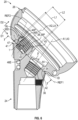
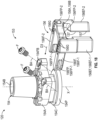
- Securing the mounting portion 24 and head portion 26 with the fastener F1 can cause the head portion 26 to move in the direction D1 across the mounting portion 24 to bind or compress the inclined face 46F of the recess 46 against the declined face 38D of the raised protrusion 38 to lock the mounting portion 24 and head portion 26 to each other in the installed position.
- Securing the fastener F1 can occur such that the inclined face 46F of the head portion 26 applies a compressive force (e.g., load) CF against the declined face 38D of the raised protrusion 38 along the ramped interface RI.
- the compressive force CF may have a major component in a direction that is substantially perpendicular to the longitudinal axis LA of the raised protrusion 38 (see also Figures 5-7 ).
- the compressive force CF may be substantially parallel to the direction D1.
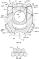
- the components 121 can include one or more Morse taper connections 127 dimensioned to limit relative axial and/or rotational movement between the components 121 (see, e.g., Figures 15-16 ).
- the components 121 can include one or more sets of teeth 133 adapted to interlock or mesh with a set of teeth 133 of an adjacent one of the components 121.
- the interlocking teeth 133 can be dimensioned to limit relative rotation between the respective components 121.
- the components 121 can be fixedly attached or otherwise secured to each other utilizing one or more fasteners.
- Each engagement flange 156EF can include at least one engagement face 157.
- the engagement face 159 can be dimensioned to contact bone or other tissue, such as a cortical wall of a long bone (see, e.g., engagement faces 257 of Figure 27 ).
- One or more surface treatments 137 can be disposed along the engagement flange 156EF to establish the respective engagement face 157 for promoting fixation with adjacent bone or other tissue (see, e.g., surface treatments 237 shown in dashed lines in Figure 27 ).
- the surface treatments 137 can include any of the treatments disclosed herein, such as a porous construct or scaffold established in a thickness of the engagement flange 156EF or one or more porous layers of material disposed on the engagement flange 156EF.
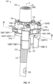
- the channel 154C of the collar portion 154 can be dimensioned to at least partially receive the flange body 156A.
- the flange body 156A can include one or more interface flanges 156IF.
- the flange portion 156 includes a set of (e.g., first and second) interface flanges 156IF-1, 156IF-2.
- the interface flanges 156IF can be dimensioned to be at least partially inserted into respective portions of the channel 154C to secure the flange portion 156 to the collar portion 154 (see also Figure 19 ).
- the support assembly 153 can include one or more features to secure the collar portion 154 and flange portion 156 to each other once a length or other dimension of the flexible construct FC is set.
- Each of the interface flanges 156IF can include a respective set of grooves 156G ( Figure 18 ).
- the collar portion 154 can include one or more fixation bores 154FB.
- Each fixation bore 154FB can extend along a respective bore axis BA.
- the fixation bore 154FB can be dimensioned such that a projection of the bore axis BA intersects the channel 154C, as illustrated in Figure 18 .
- Each of the fixation bores 154FB can be aligned with a selected groove 156G of the set of grooves 156G in the installed position.
- the support assembly 153 can include one or more fasteners F dimensioned to extend through the respective fixation bores 154FB to engage the selected groove 156G to secure the flange portion 156 and the collar portion 154 to each other in the installed
- the support assembly 153 can include one or more features to fix or otherwise set a distance between the flange portion 156 and the longitudinal axis X of the collar portion 154.
- the collar portion 154 and flange portion 156 can be secured or coupled to each other with at least one flexible construct FC (shown in dashed lines for illustrative purposes).
- the support assembly 153 can cooperate with the flexible construct(s) FC to fix or otherwise set the distance between the flange portion 156 and the longitudinal axis X of the collar portion 154.
- the support assembly 153 can cooperate with more than one flexible construct FC to fix or otherwise set the distance between the flange portion 156 and the collar portion 154.
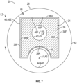
- the securement path SP can be dimensioned to receive at least a portion of the flexible construct FC.
- the flexible construct FC can be situated along at least one or more segments of the securement path SP.
- the flexible construct FC can be situated at least partially, substantially or completely along an entire length of the securement path SP. In other implementations, the flexible construct FC extends along only one or more segments of the securement path SP such that the flexible construct FC may extend along less than the entire length of the securement path SP.
- the securement path SP can be continuous or can include one or more discontinuous segments.
- the flange portion 156 can include one or more flange passages 156FP.
- the flange passages 156FP may establish respective portions of the securement path SP.
- the flange passages 156FP, channel 154C and/or collar passage 154CP can cooperate to establish respective segments of the securement path SP in the installed position.
- the first and second segments 154C-1, 154C-2 of the channel 154C and the respective flange passages 156FP-1 of the interface flanges 156IF can be at least partially aligned with each other in the installed position.
- the segments 154C-1, 154C-2 of the channel 154C, collar passage 154CP and flange passages 156FP can be substantially aligned with respect to each other relative to a reference plane that is perpendicular or otherwise transverse to the longitudinal axis X of the collar portion 154 in the installed position.
- the segments 154C-1, 154C-2 of the channel 154C, collar passage 154CP and first set of flange passages 156FP-1 can be at least partially aligned along an arc path AP in the installed position (shown in dashed lines).
- the arc path AP can extend at least partially about the longitudinal axis X of the collar portion 154.
- the arc path AP can establish a segment of the securement path SP.
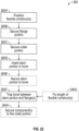
- Figure 22 illustrates a method of installing an orthopedic implant system in a flow chart 260 according to implementation.
- the method 260 can be utilized in an orthopedic procedure to restore functionality to a bone and/or joint, including any of the bones and joints disclosed herein.
- the method 260 can be utilized in repair of a fractured or shattered proximal humerus or other long bone.
- the method 260 may be utilized in an anatomical shoulder or reverse shoulder arthroplasty.
- the method 260 can be utilized with any of the implant systems disclosed herein, including implant systems 20, 120 and/or 220. Reference is made to the implant system 220 for illustrative purposes. Fewer or additional steps than are recited below could be performed within the scope of this disclosure, and the recited order of steps is not intended to limit this disclosure.
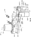
- one or more flexible constructs FC can be positioned relative to the collar portion 254 and/or flange portion 256 at step 260A (see, e.g., Figure 25 ).
- Step 260A may include looping the flexible construct FC about the collar portion 254 and flange portion 256.
- Step 260A can include passing one or more of the flexible constructs FC through the collar passage 254CP ( Figure 23 ) such that the flexible construct FC loops about the longitudinal axis X of the collar portion 254. At least a portion of each flexible construct FC can be positioned along a segment of the channel 254C.
- each flexible construct FC can be positioned through one or more of the flange passages 256FP of the flange portion 256.
- Step 260A can include positioning each flexible construct FC through each of the first set of flange passages 256FP-1 and/or the second set of flanges passage 256FP-2 (shown in dashed lines for illustrative purposes).
- Step 260B the flange portion 256 can be secured to the collar portion 254.
- Step 260B can include moving the flange portion 256 in a third direction D3 towards the longitudinal axis X of the collar portion 254 and into abutment with the collar portion 254 such that each interface flange 256IF is at least partially received along a portion of the channel 254C.
- Step 260B can include at least partially inserting at least one or more interface flanges 254IF of the flange portion 256 into the channel 254C of the collar portion 254 in response to moving the flange portion 256 in the direction D3.
- Positioning the flexible construct FC at step 260A can be performed prior to, during, and/or subsequent to securing the collar portion 254 and flange portion 256 to each other at step 260B.
- Step 260A can include passing each flexible construct FC through at least one collar passage 254CP of the collar portion 254 and through at least one or more of the flange passages 256FP of the flange portion 256 prior to fixing a specified length of the flexible construct FC.
- the collar portion 254 and stem portion 222 can be secured to each other at step 260C utilizing any of the techniques disclosed herein.
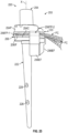
- the stem portion 222 can be inserted into bone B at step 260D (stem portion 222 shown in dashed lines).
- Step 260D can include moving the stem portion in a fourth direction D4 such that at least a portion of the stem portion 222 is inserted into an intramedullary canal IC of the bone B (shown in dashed lines).
- the bone B may be any of the bones disclosed herein, such as a proximal humerus or another long bone of a patient.
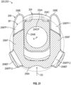
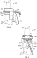
- Step 260D may include removing bone fragments from the surgical site and resecting the bone B to establish a resection surface RS prior to positioning the stem portion 222. Step 260D can occur such that the body 254A of the collar portion 254 sits on the resected surface RS of the bone B, as illustrated in Figure 27 .
- the stem portion 222 can be secured to the bone B at step 260E.
- the stem portion 222 can include one or more fixation bores 228 ( Figure 25 ).
- Step 260E can include positioning bone fasteners through each of the respective fixation bores 228 and into the bone B prior to fixing the length of each flexible construct FC (see, e.g., fasteners F of Figure 2 ).
- Step 260F can include fixing a length of the respective flexible construct FC to secure or couple the collar portion 254 and flange portion 256 to each other at step 260G.
- Step 260A can include looping one or more of the flexible constructs FC around the periphery 254P of the collar portion 254 and through the flange passages 256FP of the flange portion 256 and then tensioning the flexible construct FC at step 260F prior to fixing the length of the flexible construct FC at step 260G.
- Step 260F can include tensioning the flexible construct(s) FC to cause the flange portion 256 to be drawn in the direction D3 towards the collar portion 254 and then tying the flexible construct FC in a knot at step 260G, as illustrated in Figure 27 .
- Other techniques can be utilized to fix the length of flexible construct FC including securing one or more clips or other fasteners onto the flexible construct FC to the establish or set the specified length of the flexible construct FC.
- Step 260G can include fixing the selected position of the flange portion 256 relative to the collar portion 254, such as by inserting fasteners F in respective fixation bores 254FB to engage the respective grooves 256G (see Figure 20 , see also Figures 17-18 ).
- one or more components of the implant system 220 can be secured to the collar portion 254.
- the collar portion 254 can interconnect the stem portion 222, intermediate portions and/or a head portion adapted to mount an articulation member (see, e.g., implant system 120 of Figures 14 and 15 ).
- Method 260 can include one or more additional steps performed prior to, during, or subsequent to steps 260A-260H.
- Method 260 can include positioning one or more bone fragments and/or soft tissue about the implant system 220, and situating the articular portion relative to an opposed articular surface to restore functionality to a joint (see, e.g., implant system 20 of Figure 2 ).
- the novel implant systems and methods of this disclosure may provide versatility in repairing bone defects restoring functionality to bones and/or joints.
- the disclosed implant systems described herein may include a taper locking mechanism to limit or otherwise oppose separation between the components, which may improve fixation and healing of the patient.
- the disclosed implant systems may include one or more flanges adapted to abut an exterior of the bone to promote torsional stability when the implant system is placed under torsional loads.
- One or more flexible constructs may be utilized to secure the flanges to another component of the implant system at a specified distance to apply a compress force or load on the exterior of the bone, which may promote alignment and functionality of the restored joint and healing of the patient.
Landscapes
- Health & Medical Sciences (AREA)
- Orthopedic Medicine & Surgery (AREA)
- Cardiology (AREA)
- Oral & Maxillofacial Surgery (AREA)
- Transplantation (AREA)
- Engineering & Computer Science (AREA)
- Biomedical Technology (AREA)
- Heart & Thoracic Surgery (AREA)
- Vascular Medicine (AREA)
- Life Sciences & Earth Sciences (AREA)
- Animal Behavior & Ethology (AREA)
- General Health & Medical Sciences (AREA)
- Public Health (AREA)
- Veterinary Medicine (AREA)
- Prostheses (AREA)
Claims (8)
- Orthopädisches Implantatsystem, umfassend:einen Schaftabschnitt (22), der in Knochen einführbar ist;einen Befestigungsabschnitt (24), der sich von dem Schaftabschnitt (22) erstreckt, wobei der Befestigungsabschnitt (24) eine erste Befestigungsbohrung (36), die sich von einer ersten Eingriffsfläche (34) nach innen erstreckt, und einen erhabenen Vorsprung (38) beinhaltet, der sich von der ersten Eingriffsfläche (34) nach außen erstreckt, und wobei sich der erhabene Vorsprung (38) entlang einer abfallenden Fläche (38D) zu der ersten Eingriffsfläche (34) hin verjüngt;einen Kopfabschnitt (26), der dazu ausgelegt ist, ein Gelenkelement (30) zu befestigen, wobei der Kopfabschnitt (26) eine Aussparung (46) beinhaltet, die sich von der zweiten Eingriffsfläche (42) nach innen erstreckt, wobei ein Umfang der Aussparung (46) eine ansteigende Fläche (46F) beinhaltet, die zu einer Öffnung (46E) der Aussparung (46) entlang der zweiten Eingriffsfläche (42) hin geneigt ist;wobei der erhabene Vorsprung (38) durch die Öffnung (46E) und in die Aussparung (46) einführbar ist, sodass die abfallende Fläche (38D) und die ansteigende Fläche (46F) in einer installierten Position aneinander anliegen;dadurch gekennzeichnet, dassder Kopfabschnitt (26) eine Kopfbohrung (44) beinhaltet, die sich von einer zweiten Eingriffsfläche (42) nach innen erstreckt,wobei sich die erste Befestigungsbohrung (36) entlang einer ersten Befestigungsbohrungsachse (Al) in einer Richtung weg von dem erhabenen Vorsprung (38) erstreckt, sodass sich die ansteigende Fläche (46F) in Reaktion auf das Befestigen eines gemeinsamen Befestigungselements (F) in der Kopfbohrung (44) und der ersten Befestigungsbohrung in Richtung der ersten Befestigungsbohrungsachse (Al) bewegt, um die ansteigende Fläche (46F) gegen die abfallende Fläche (38D) zu drücken.
- System nach Anspruch 1, wobei das Gelenkelement (30) dazu ausgelegt ist, mit einer gegenüberliegenden Gelenkfläche eines benachbarten Implantats oder eines benachbarten Knochens zusammenzupassen.
- System nach Anspruch 1 oder 2, wobei eine maximale Länge des erhabenen Vorsprungs (38) größer als eine minimale Länge der Öffnung (46E) ist.
- System nach einem der vorhergehenden Ansprüche, wobei die zweite Eingriffsfläche (42) des Kopfabschnitts (26) in Reaktion auf eine Drehung des gemeinsamen Befestigungselements (F) um die erste Befestigungsbohrungsachse (Al) über die erste Eingriffsfläche (34) gleitet.
- System nach einem der vorhergehenden Ansprüche, wobei:die erste Eingriffsfläche (34) des Befestigungsabschnitts (24) sich entlang einer ersten Bezugsebene (REFI) erstreckt und die erste Befestigungsbohrungsachse (Al) die erste Bezugsebene (REFI) schneidet, um einen spitzen ersten Bohrungswinkel (β) zu bilden;die abfallende Fläche (38D) des erhabenen Vorsprungs (38) sich entlang einer zweiten Bezugsebene erstreckt und die zweite Bezugsebene die erste Bezugsebene (REFI) schneidet, um einen spitzen Eintauchwinkel (α) zu bilden; undder Eintauchwinkel (α) kleiner als der erste Bohrungswinkel (β) ist.
- System nach einem der vorhergehenden Ansprüche, wobei der erhabene Vorsprung (38) eine zweite Befestigungsbohrung (40) beinhaltet, die sich entlang einer zweiten Befestigungsbohrungsachse (A2) erstreckt, wobei die zweite Befestigungsbohrung (40) so bemessen ist, dass sie ein Befestigungselement (F) aufnimmt, um einen Adapter an dem Befestigungsabschnitt (24) zu befestigen, und wobei der Adapter dazu ausgelegt ist, den Kopfabschnitt (26) und das Gelenkelement (30) miteinander zu verbinden.
- System nach Anspruch 6, wobei die zweite Befestigungsbohrungsachse (A2) die erste Bezugsebene (REFI) schneidet, um einen zweiten Bohrungswinkel (y) zu bilden, und der zweite Bohrungswinkel (y) sich von dem ersten Bohrungswinkel (β) unterscheidet und sich von dem Eintauchwinkel (α) unterscheidet.
- System nach einem der vorhergehenden Ansprüche, wobei:der Kopfabschnitt (26) ein Paar Wände (46W) beinhaltet, die die ansteigende Fläche (46F) und eine bogenförmige Lippe (46L) miteinander verbinden, um den Umfang der Aussparung (46) zu bilden, wobei das Paar Wände (46W) einander auf gegenüberliegenden Seiten der Kopfbohrung (44) gegenüberliegt, wobei die bogenförmige Lippe (46L) der ansteigenden Fläche (46F) gegenüberliegt und so bemessen ist, dass sie einem Umfang (44P) der Kopfbohrung (44) folgt; undder Befestigungsabschnitt (24) ein Paar Flächen (38F) auf gegenüberliegenden Seiten des erhabenen Vorsprungs (38) beinhaltet, wobei die abfallende Fläche (38D) das Paar Flächen (38F) miteinander verbindet und das Paar Flächen (38F) so bemessen ist, dass es mit dem entsprechenden Paar Wände (46W) in Eingriff kommt, um die relative Bewegung zwischen dem Kopfabschnitt (26) und dem Befestigungsabschnitt (24) in der installierten Position zu begrenzen.
Priority Applications (1)
| Application Number | Priority Date | Filing Date | Title |
|---|---|---|---|
| EP25155689.0A EP4523661A3 (de) | 2022-09-09 | 2023-08-07 | Orthopädische implantatsysteme mit befestigungsmerkmalen |
Applications Claiming Priority (2)
| Application Number | Priority Date | Filing Date | Title |
|---|---|---|---|
| US17/942,046 US12472067B2 (en) | 2022-09-09 | 2022-09-09 | Orthopaedic implant systems including fixation features and methods of repair |
| PCT/US2023/029605 WO2024054324A1 (en) | 2022-09-09 | 2023-08-07 | Orthopaedic implant systems including fixation features |
Related Child Applications (2)
| Application Number | Title | Priority Date | Filing Date |
|---|---|---|---|
| EP25155689.0A Division-Into EP4523661A3 (de) | 2022-09-09 | 2023-08-07 | Orthopädische implantatsysteme mit befestigungsmerkmalen |
| EP25155689.0A Division EP4523661A3 (de) | 2022-09-09 | 2023-08-07 | Orthopädische implantatsysteme mit befestigungsmerkmalen |
Publications (3)
| Publication Number | Publication Date |
|---|---|
| EP4429601A1 EP4429601A1 (de) | 2024-09-18 |
| EP4429601B1 true EP4429601B1 (de) | 2025-03-26 |
| EP4429601C0 EP4429601C0 (de) | 2025-03-26 |
Family
ID=87848129
Family Applications (2)
| Application Number | Title | Priority Date | Filing Date |
|---|---|---|---|
| EP25155689.0A Pending EP4523661A3 (de) | 2022-09-09 | 2023-08-07 | Orthopädische implantatsysteme mit befestigungsmerkmalen |
| EP23762067.9A Active EP4429601B1 (de) | 2022-09-09 | 2023-08-07 | Orthopädische implantatsysteme mit fixierungselementen |
Family Applications Before (1)
| Application Number | Title | Priority Date | Filing Date |
|---|---|---|---|
| EP25155689.0A Pending EP4523661A3 (de) | 2022-09-09 | 2023-08-07 | Orthopädische implantatsysteme mit befestigungsmerkmalen |
Country Status (3)
| Country | Link |
|---|---|
| US (1) | US12472067B2 (de) |
| EP (2) | EP4523661A3 (de) |
| WO (1) | WO2024054324A1 (de) |
Families Citing this family (2)
| Publication number | Priority date | Publication date | Assignee | Title |
|---|---|---|---|---|
| US11039929B2 (en) * | 2009-07-10 | 2021-06-22 | Peter Mats Forsell | Hip joint device and method |
| EP3838224B1 (de) * | 2019-12-16 | 2023-08-09 | Waldemar Link GmbH & Co. KG | Humerusimplantatkomponente |
Family Cites Families (43)
| Publication number | Priority date | Publication date | Assignee | Title |
|---|---|---|---|---|
| US4012796A (en) | 1975-09-24 | 1977-03-22 | Howmedica, Inc. | Interpositioning collar for prosthetic bone insert |
| US5108452A (en) | 1989-02-08 | 1992-04-28 | Smith & Nephew Richards Inc. | Modular hip prosthesis |
| FR2685633B1 (fr) | 1991-12-27 | 1998-02-27 | Tornier Sa | Prothese humerale modulaire. |
| US5961555A (en) * | 1998-03-17 | 1999-10-05 | Huebner; Randall J. | Modular shoulder prosthesis |
| US5507817A (en) | 1994-02-22 | 1996-04-16 | Kirschner Medical Corporation | Modular humeral prosthesis for reconstruction of the humerus |
| FR2718954B1 (fr) | 1994-04-25 | 1996-08-02 | Euros Sa | Ensemble prothétique modulaire pour l'articulation de l'épaule. |
| US5746771A (en) | 1996-09-30 | 1998-05-05 | Wright Medical Technology, Inc. | Calcar collar instrumentation |
| FR2767674B1 (fr) | 1997-08-29 | 1999-12-31 | Vecteur Orthopedic | Prothese de l'extremite superieure de l'humerus |
| FR2773469B1 (fr) | 1998-01-09 | 2000-03-03 | Alain Leonard | Equipement chirurgical pour l'implantation d'une prothese totale d'epaule, et prothese totale d'epaule constitutive |
| DE29918589U1 (de) | 1999-09-24 | 2000-01-27 | Bähler, André, Zürich | Endoprothese für ein Schultergelenk |
| US6436145B1 (en) | 2000-06-02 | 2002-08-20 | Zimmer, Inc. | Plug for a modular orthopaedic implant and method for assembly |
| US6447549B1 (en) | 2000-10-06 | 2002-09-10 | Sulzer Orthopedics Inc. | Modular knee prosthesis system |
| US6942699B2 (en) | 2001-07-11 | 2005-09-13 | Biomet, Inc. | Shoulder prosthesis |
| DE20120703U1 (de) | 2001-12-21 | 2002-03-07 | KERAMED Medizintechnik GmbH, 07646 Mörsdorf | Schulterprothese |
| US7175664B1 (en) | 2002-07-03 | 2007-02-13 | Biomet, Inc. | Prosthetic having a modular soft tissue fixation mechanism |
| US7175663B1 (en) | 2003-10-08 | 2007-02-13 | Biomet Manufacturing Corp. | Shoulder implant assembly |
| US6866683B2 (en) | 2002-12-13 | 2005-03-15 | Medicine Lodge, Inc. | Modular implant for joint reconstruction and method of use |
| US20040167629A1 (en) | 2003-02-03 | 2004-08-26 | Geremakis Perry A. | Modular shoulder prosthesis |
| FR2876899A1 (fr) * | 2004-10-25 | 2006-04-28 | Depuy Ireland Ltd | Prothese humerale modulaire pour prothese d'epaule inversee |
| US7867282B2 (en) | 2004-12-17 | 2011-01-11 | Depuy Products, Inc. | Modular implant system and method with diaphyseal implant and adapter |
| US20060155381A1 (en) | 2005-01-07 | 2006-07-13 | Orthopaedic Development, Llc | Orthopedic system for total hip replacement surgery |
| US20060173415A1 (en) | 2005-01-11 | 2006-08-03 | Christy Cummins | Syringe adaptor |
| TWI434675B (zh) | 2006-02-06 | 2014-04-21 | Conformis Inc | 患者可選擇式關節置換術裝置及外科工具 |
| ITMI20061568A1 (it) | 2006-08-03 | 2008-02-04 | Plustek S R L | Protesi di spalla |
| US8562616B2 (en) | 2007-10-10 | 2013-10-22 | Biomet Manufacturing, Llc | Knee joint prosthesis system and method for implantation |
| US9814583B2 (en) | 2007-05-08 | 2017-11-14 | Zimmer, Inc. | Modular stem extension |
| FR2920963B1 (fr) | 2007-09-19 | 2010-09-10 | Tornier Sa | Composant de prothese articulaire et prothese articulaire comprenant un tel composant |
| DE102008010478A1 (de) | 2008-02-21 | 2009-08-27 | Smith & Nephew Orthopaedics Ag | Schultergelenkprothese, insbesondere inverse Schultergelenkprothese |
| US8454706B2 (en) | 2009-02-25 | 2013-06-04 | Brian C. de Beaubien | Antibiotic delivery system and method for treating an infected synovial joint during re-implantation of an orthopedic prosthesis |
| FR2951633A1 (fr) | 2009-10-23 | 2011-04-29 | Wilko Fockens | Prothese d'epaule a tige universelle avec vis d'osteosynthese verrouillees |
| US8500819B2 (en) | 2010-03-05 | 2013-08-06 | Biomet Manufacturing, Llc | Drug delivery and diagnostic system for orthopedic implants |
| CA2907537C (en) | 2012-08-01 | 2020-08-25 | Exactech, Inc. | Prosthetic devices to improve joint mechanics in arthroplasty |
| US9039778B2 (en) | 2013-04-16 | 2015-05-26 | Brian G. Burnikel | Modular, adjustable, prosthetic, hip/shoulder spacer |
| US9492184B2 (en) | 2013-08-05 | 2016-11-15 | William B. Kurtz | Hip replacement systems and methods |
| US9956083B2 (en) | 2013-12-30 | 2018-05-01 | Deltoid, Llc | Instruments and techniques for orienting prosthesis components for joint prostheses |
| US9597190B2 (en) | 2015-01-15 | 2017-03-21 | DePuy Synthes Products, Inc. | Modular reverse shoulder orthopaedic implant and method of implanting the same |
| US10251752B2 (en) | 2015-12-31 | 2019-04-09 | DePuy Synthes Products, Inc. | Modular femoral prosthesis system for hip arthroplasty |
| US10390972B2 (en) | 2016-01-15 | 2019-08-27 | Howmedica Osteonics Corp. | Humeral trial adaptor |
| US10251744B2 (en) | 2017-01-27 | 2019-04-09 | Onkos Surgical, Inc. | Soft tissue fixation device |
| EP3520738B1 (de) | 2018-01-31 | 2021-01-06 | Tornier | Prothese für einen gebrochenen langen knochen |
| CA3095865A1 (en) | 2018-04-04 | 2019-10-10 | Tornier, Inc. | Modular humeral stem with fine adjustment |
| AU2021202801A1 (en) | 2020-05-07 | 2021-11-25 | Howmedica Osteonics Corp. | Stemless metaphyseal humeral implant |
| MX2023014742A (es) | 2021-06-11 | 2024-04-01 | Encore Medical L P D/B/A/ Djo Surgical | Componentes ortopedicos. |
-
2022
- 2022-09-09 US US17/942,046 patent/US12472067B2/en active Active
-
2023
- 2023-08-07 EP EP25155689.0A patent/EP4523661A3/de active Pending
- 2023-08-07 WO PCT/US2023/029605 patent/WO2024054324A1/en not_active Ceased
- 2023-08-07 EP EP23762067.9A patent/EP4429601B1/de active Active
Also Published As
| Publication number | Publication date |
|---|---|
| EP4429601A1 (de) | 2024-09-18 |
| US12472067B2 (en) | 2025-11-18 |
| WO2024054324A1 (en) | 2024-03-14 |
| EP4429601C0 (de) | 2025-03-26 |
| US20240082005A1 (en) | 2024-03-14 |
| EP4523661A2 (de) | 2025-03-19 |
| EP4523661A3 (de) | 2025-05-14 |
Similar Documents
| Publication | Publication Date | Title |
|---|---|---|
| EP4429601B1 (de) | Orthopädische implantatsysteme mit fixierungselementen | |
| US8574235B2 (en) | Method for trochanteric reattachment | |
| JP5917569B2 (ja) | 関節形成プレート | |
| CA2218598C (en) | Intramedullary bone plug | |
| EP1810643A2 (de) | Hüftgelenkkopf mit starren Befestigungselementen. | |
| CA2643678A1 (en) | Orthopaedic fixation component and method | |
| AU2018203460B2 (en) | Hip joint device and method | |
| McCarthy et al. | The outcome of trochanteric reattachment in revision total hip arthroplasty with a Cable Grip System: mean 6-year follow-up | |
| CA2804978C (en) | Hip joint device and method | |
| CA3043393C (en) | Hip joint device and method | |
| US20240415664A1 (en) | Hip joint and method | |
| US20250345177A1 (en) | Suture hole geometry and methods for attaching tissue to orthopedic implants | |
| KR20010082116A (ko) | 관절 보철물 및 앵커링 수단 | |
| US11504173B2 (en) | Bone-stabilizing device having a pivotable buttress member | |
| WO2003075801A1 (en) | Improved socket prosthesis | |
| US12496192B2 (en) | Hydraulic taper separator for orthopaedic implant systems and methods of disassembly | |
| RU2113831C1 (ru) | Эндопротез сустава пальца кисти |
Legal Events
| Date | Code | Title | Description |
|---|---|---|---|
| STAA | Information on the status of an ep patent application or granted ep patent |
Free format text: STATUS: UNKNOWN |
|
| STAA | Information on the status of an ep patent application or granted ep patent |
Free format text: STATUS: THE INTERNATIONAL PUBLICATION HAS BEEN MADE |
|
| PUAI | Public reference made under article 153(3) epc to a published international application that has entered the european phase |
Free format text: ORIGINAL CODE: 0009012 |
|
| STAA | Information on the status of an ep patent application or granted ep patent |
Free format text: STATUS: REQUEST FOR EXAMINATION WAS MADE |
|
| 17P | Request for examination filed |
Effective date: 20240612 |
|
| AK | Designated contracting states |
Kind code of ref document: A1 Designated state(s): AL AT BE BG CH CY CZ DE DK EE ES FI FR GB GR HR HU IE IS IT LI LT LU LV MC ME MK MT NL NO PL PT RO RS SE SI SK SM TR |
|
| GRAP | Despatch of communication of intention to grant a patent |
Free format text: ORIGINAL CODE: EPIDOSNIGR1 |
|
| STAA | Information on the status of an ep patent application or granted ep patent |
Free format text: STATUS: GRANT OF PATENT IS INTENDED |
|
| DAV | Request for validation of the european patent (deleted) | ||
| INTG | Intention to grant announced |
Effective date: 20241112 |
|
| GRAS | Grant fee paid |
Free format text: ORIGINAL CODE: EPIDOSNIGR3 |
|
| GRAA | (expected) grant |
Free format text: ORIGINAL CODE: 0009210 |
|
| STAA | Information on the status of an ep patent application or granted ep patent |
Free format text: STATUS: THE PATENT HAS BEEN GRANTED |
|
| RAP3 | Party data changed (applicant data changed or rights of an application transferred) |
Owner name: ARTHREX, INC. |
|
| AK | Designated contracting states |
Kind code of ref document: B1 Designated state(s): AL AT BE BG CH CY CZ DE DK EE ES FI FR GB GR HR HU IE IS IT LI LT LU LV MC ME MK MT NL NO PL PT RO RS SE SI SK SM TR |
|
| DAX | Request for extension of the european patent (deleted) | ||
| REG | Reference to a national code |
Ref country code: GB Ref legal event code: FG4D |
|
| REG | Reference to a national code |
Ref country code: CH Ref legal event code: EP |
|
| REG | Reference to a national code |
Ref country code: DE Ref legal event code: R096 Ref document number: 602023002625 Country of ref document: DE |
|
| REG | Reference to a national code |
Ref country code: IE Ref legal event code: FG4D |
|
| U01 | Request for unitary effect filed |
Effective date: 20250423 |
|
| U07 | Unitary effect registered |
Designated state(s): AT BE BG DE DK EE FI FR IT LT LU LV MT NL PT RO SE SI Effective date: 20250429 |
|
| PG25 | Lapsed in a contracting state [announced via postgrant information from national office to epo] |
Ref country code: RS Free format text: LAPSE BECAUSE OF FAILURE TO SUBMIT A TRANSLATION OF THE DESCRIPTION OR TO PAY THE FEE WITHIN THE PRESCRIBED TIME-LIMIT Effective date: 20250626 |
|
| PG25 | Lapsed in a contracting state [announced via postgrant information from national office to epo] |
Ref country code: NO Free format text: LAPSE BECAUSE OF FAILURE TO SUBMIT A TRANSLATION OF THE DESCRIPTION OR TO PAY THE FEE WITHIN THE PRESCRIBED TIME-LIMIT Effective date: 20250626 |
|
| PG25 | Lapsed in a contracting state [announced via postgrant information from national office to epo] |
Ref country code: HR Free format text: LAPSE BECAUSE OF FAILURE TO SUBMIT A TRANSLATION OF THE DESCRIPTION OR TO PAY THE FEE WITHIN THE PRESCRIBED TIME-LIMIT Effective date: 20250326 |
|
| PG25 | Lapsed in a contracting state [announced via postgrant information from national office to epo] |
Ref country code: GR Free format text: LAPSE BECAUSE OF FAILURE TO SUBMIT A TRANSLATION OF THE DESCRIPTION OR TO PAY THE FEE WITHIN THE PRESCRIBED TIME-LIMIT Effective date: 20250627 |
|
| U20 | Renewal fee for the european patent with unitary effect paid |
Year of fee payment: 3 Effective date: 20250709 |
|
| PG25 | Lapsed in a contracting state [announced via postgrant information from national office to epo] |
Ref country code: SM Free format text: LAPSE BECAUSE OF FAILURE TO SUBMIT A TRANSLATION OF THE DESCRIPTION OR TO PAY THE FEE WITHIN THE PRESCRIBED TIME-LIMIT Effective date: 20250326 |
|
| PG25 | Lapsed in a contracting state [announced via postgrant information from national office to epo] |
Ref country code: ES Free format text: LAPSE BECAUSE OF FAILURE TO SUBMIT A TRANSLATION OF THE DESCRIPTION OR TO PAY THE FEE WITHIN THE PRESCRIBED TIME-LIMIT Effective date: 20250326 |
|
| PG25 | Lapsed in a contracting state [announced via postgrant information from national office to epo] |
Ref country code: PL Free format text: LAPSE BECAUSE OF FAILURE TO SUBMIT A TRANSLATION OF THE DESCRIPTION OR TO PAY THE FEE WITHIN THE PRESCRIBED TIME-LIMIT Effective date: 20250326 |
|
| PG25 | Lapsed in a contracting state [announced via postgrant information from national office to epo] |
Ref country code: SK Free format text: LAPSE BECAUSE OF FAILURE TO SUBMIT A TRANSLATION OF THE DESCRIPTION OR TO PAY THE FEE WITHIN THE PRESCRIBED TIME-LIMIT Effective date: 20250326 |
|
| PG25 | Lapsed in a contracting state [announced via postgrant information from national office to epo] |
Ref country code: IS Free format text: LAPSE BECAUSE OF FAILURE TO SUBMIT A TRANSLATION OF THE DESCRIPTION OR TO PAY THE FEE WITHIN THE PRESCRIBED TIME-LIMIT Effective date: 20250726 |