EP4429421A1 - Din rail, electronic component assembly and energy storage system comprising same - Google Patents
Din rail, electronic component assembly and energy storage system comprising same Download PDFInfo
- Publication number
- EP4429421A1 EP4429421A1 EP23846942.3A EP23846942A EP4429421A1 EP 4429421 A1 EP4429421 A1 EP 4429421A1 EP 23846942 A EP23846942 A EP 23846942A EP 4429421 A1 EP4429421 A1 EP 4429421A1
- Authority
- EP
- European Patent Office
- Prior art keywords
- electronic component
- din
- rail
- present disclosure
- collection space
- Prior art date
- Legal status (The legal status is an assumption and is not a legal conclusion. Google has not performed a legal analysis and makes no representation as to the accuracy of the status listed.)
- Granted
Links
Images




Classifications
-
- H—ELECTRICITY
- H05—ELECTRIC TECHNIQUES NOT OTHERWISE PROVIDED FOR
- H05K—PRINTED CIRCUITS; CASINGS OR CONSTRUCTIONAL DETAILS OF ELECTRIC APPARATUS; MANUFACTURE OF ASSEMBLAGES OF ELECTRICAL COMPONENTS
- H05K7/00—Constructional details common to different types of electric apparatus
- H05K7/02—Arrangements of circuit components or wiring on supporting structure
- H05K7/12—Resilient or clamping means for holding component to structure
-
- H—ELECTRICITY
- H01—ELECTRIC ELEMENTS
- H01M—PROCESSES OR MEANS, e.g. BATTERIES, FOR THE DIRECT CONVERSION OF CHEMICAL ENERGY INTO ELECTRICAL ENERGY
- H01M10/00—Secondary cells; Manufacture thereof
- H01M10/60—Heating or cooling; Temperature control
- H01M10/62—Heating or cooling; Temperature control specially adapted for specific applications
- H01M10/627—Stationary installations, e.g. power plant buffering or backup power supplies
-
- H—ELECTRICITY
- H01—ELECTRIC ELEMENTS
- H01M—PROCESSES OR MEANS, e.g. BATTERIES, FOR THE DIRECT CONVERSION OF CHEMICAL ENERGY INTO ELECTRICAL ENERGY
- H01M10/00—Secondary cells; Manufacture thereof
- H01M10/60—Heating or cooling; Temperature control
- H01M10/65—Means for temperature control structurally associated with the cells
- H01M10/655—Solid structures for heat exchange or heat conduction
- H01M10/6551—Surfaces specially adapted for heat dissipation or radiation, e.g. fins or coatings
-
- H—ELECTRICITY
- H01—ELECTRIC ELEMENTS
- H01M—PROCESSES OR MEANS, e.g. BATTERIES, FOR THE DIRECT CONVERSION OF CHEMICAL ENERGY INTO ELECTRICAL ENERGY
- H01M50/00—Constructional details or processes of manufacture of the non-active parts of electrochemical cells other than fuel cells, e.g. hybrid cells
- H01M50/60—Arrangements or processes for filling or topping-up with liquids; Arrangements or processes for draining liquids from casings
- H01M50/691—Arrangements or processes for draining liquids from casings; Cleaning battery or cell casings
-
- H—ELECTRICITY
- H02—GENERATION; CONVERSION OR DISTRIBUTION OF ELECTRIC POWER
- H02B—BOARDS, SUBSTATIONS OR SWITCHING ARRANGEMENTS FOR THE SUPPLY OR DISTRIBUTION OF ELECTRIC POWER
- H02B1/00—Frameworks, boards, panels, desks, casings; Details of substations or switching arrangements
- H02B1/015—Boards, panels, desks; Parts thereof or accessories therefor
- H02B1/04—Mounting thereon of switches or of other devices in general, the switch or device having, or being without, casing
- H02B1/052—Mounting on rails
-
- H—ELECTRICITY
- H05—ELECTRIC TECHNIQUES NOT OTHERWISE PROVIDED FOR
- H05K—PRINTED CIRCUITS; CASINGS OR CONSTRUCTIONAL DETAILS OF ELECTRIC APPARATUS; MANUFACTURE OF ASSEMBLAGES OF ELECTRICAL COMPONENTS
- H05K5/00—Casings, cabinets or drawers for electric apparatus
- H05K5/02—Details
- H05K5/0204—Mounting supporting structures on the outside of casings
-
- H—ELECTRICITY
- H05—ELECTRIC TECHNIQUES NOT OTHERWISE PROVIDED FOR
- H05K—PRINTED CIRCUITS; CASINGS OR CONSTRUCTIONAL DETAILS OF ELECTRIC APPARATUS; MANUFACTURE OF ASSEMBLAGES OF ELECTRICAL COMPONENTS
- H05K5/00—Casings, cabinets or drawers for electric apparatus
- H05K5/02—Details
- H05K5/0213—Venting apertures; Constructional details thereof
- H05K5/0214—Venting apertures; Constructional details thereof with means preventing penetration of rain water or dust
-
- H—ELECTRICITY
- H05—ELECTRIC TECHNIQUES NOT OTHERWISE PROVIDED FOR
- H05K—PRINTED CIRCUITS; CASINGS OR CONSTRUCTIONAL DETAILS OF ELECTRIC APPARATUS; MANUFACTURE OF ASSEMBLAGES OF ELECTRICAL COMPONENTS
- H05K7/00—Constructional details common to different types of electric apparatus
- H05K7/14—Mounting supporting structure in casing or on frame or rack
- H05K7/1422—Printed circuit boards receptacles, e.g. stacked structures, electronic circuit modules or box like frames
- H05K7/1427—Housings
- H05K7/1432—Housings specially adapted for power drive units or power converters
- H05K7/14324—Housings specially adapted for power drive units or power converters comprising modular units, e.g. DIN rail mounted units
-
- H—ELECTRICITY
- H02—GENERATION; CONVERSION OR DISTRIBUTION OF ELECTRIC POWER
- H02B—BOARDS, SUBSTATIONS OR SWITCHING ARRANGEMENTS FOR THE SUPPLY OR DISTRIBUTION OF ELECTRIC POWER
- H02B1/00—Frameworks, boards, panels, desks, casings; Details of substations or switching arrangements
- H02B1/26—Casings; Parts thereof or accessories therefor
- H02B1/28—Casings; Parts thereof or accessories therefor dustproof, splashproof, drip-proof, waterproof or flameproof
-
- Y—GENERAL TAGGING OF NEW TECHNOLOGICAL DEVELOPMENTS; GENERAL TAGGING OF CROSS-SECTIONAL TECHNOLOGIES SPANNING OVER SEVERAL SECTIONS OF THE IPC; TECHNICAL SUBJECTS COVERED BY FORMER USPC CROSS-REFERENCE ART COLLECTIONS [XRACs] AND DIGESTS
- Y02—TECHNOLOGIES OR APPLICATIONS FOR MITIGATION OR ADAPTATION AGAINST CLIMATE CHANGE
- Y02E—REDUCTION OF GREENHOUSE GAS [GHG] EMISSIONS, RELATED TO ENERGY GENERATION, TRANSMISSION OR DISTRIBUTION
- Y02E60/00—Enabling technologies; Technologies with a potential or indirect contribution to GHG emissions mitigation
- Y02E60/10—Energy storage using batteries
Definitions
- the present disclosure relates to a DIN-rail, and an electronic component assembly and an energy storage system including the same. More specifically, the present disclosure relates to a DIN-rail for fixing electronic components, which may prevent deterioration of the insulation performance of electronic components by applying a structure capable of preventing condensation caused by rapid outdoor environmental changes and draining moisture, and an electronic component assembly and an energy storage system including the same.
- an energy storage system for storing generated power has been receiving a lot of attention.
- ESS energy storage system
- it is easy to build a power management system such as a smart grid system, making it possible to easily control power supply in a specific region or city.
- this energy storage system can also be applied to electric charging stations where electric vehicles can be charged.
- the energy storage system may be configured in various forms, but may be typically configured to include one or more battery containers.
- the battery container may include a plurality of battery modules connected to each other in series and/or parallel.
- the plurality of battery modules may be stored inside the battery container through a rack frame or a separate fixing structure. Since the energy storage system including a plurality of battery modules handles a very large amount of power, it essentially includes a circuit breaker that plays a role of protecting circuits and loads by blocking the line when a fault current such as overload, instantaneous current, or phase loss occurs on the electric line, and various electronic components are also included. These electronic components are coupled and fixed to a DIN-rail attached to a switchboard, etc.
- the present disclosure is designed to solve the problems of the related art, and therefore the present disclosure is directed to providing a DIN-rail for fixing electronic components, which may prevent the deterioration of the insulation performance of electronic components by applying a structure capable of preventing moisture from entering the electronic components and effectively draining the moisture even if condensation occurs due to, for example, rapid outdoor environmental changes.
- Another object of the present disclosure is to provide an electronic component assembly that can prevent deterioration of insulation performance by including this DIN-rail, and an energy storage system including the same.
- a DIN-rail for fixing an electronic component comprises a body unit disposed on one side of the electronic component and configured to be coupled with the electronic component; and a protection unit connected to the body unit, configured to cover the upper part of the electronic component, and configured to discharge fluid so that the fluid falling along the direction of gravity does not contact the electronic component.
- the protection unit may include a first portion configured to cover the electronic component and configured to collect the fluid; and a second portion configured to extend from the first portion to the outside of the electronic component and configured to discharge fluid collected by the first portion.
- the area of the first portion may be larger than the area of the electronic component so that the electronic component is not exposed to the outside of the first portion.
- the first portion may have a first collection space with an embedded shape in a direction toward the electronic component.
- the bottom surface of the first collection space may have a downward sloping shape toward the second portion.
- the second portion may have a second collection space configured to communicate with the first collection space, and a discharge hole may be formed in the bottom surface of the second collection space to discharge the fluid.
- the second collection space may be formed deeper than the first collection space.
- the discharge hole may be formed in the area corresponding to the opposite side of the electronic component based on the body unit.
- the DIN-rail may contain a resin material.
- an electronic component assembly according to the present disclosure comprises the DIN-rail according to the present disclosure.
- the electronic component may be a circuit breaker.
- an energy storage system according to the present disclosure comprises the electronic component assembly according to the present disclosure.
- the energy storage system may comprise a battery pack including a plurality of secondary batteries; a heat sink coupled to the battery pack and configured to cool the battery pack; and the electronic component configured to collect and discharge fluid generated from the heat sink.
- the electronic component assembly may be coupled to at least one of the battery pack and the heat sink.
- the electronic component assembly may be located lower than the heat sink along the direction of gravity.
- the electronic components in a DIN-rail that couples electronic components through a body unit, can be protected from external physical factors by providing a protection unit. For example, it is possible to protect electronic components from moisture generated by condensation due to rapid changes in temperature, and prevent deterioration of the insulation performance of the electronic components by discharging moisture so that it does not come into contact with the electronic components.
- the DIN-rail itself also has insulation performance, it is possible to more effectively prevent deterioration of the insulation performance of electronic components.
- electronic components can be more effectively protected from physical external factors, and, for example, moisture resulting from condensation caused by rapid changes in temperature or fluid containing such moisture can be collected and discharged more effectively.
- fluid discharged through the discharge hole may not affect electronic components during and after discharge.
- efficient discharge of fluid is possible by controlling the discharge direction and location of fluid through the discharge hole.
- the present disclosure may have various other effects, and these will be explained in each embodiment, or the explanation will be omitted for effects that can be easily inferred by a person skilled in the art.
- FIG. 1 is a perspective view showing the appearance of a DIN-rail 300 according to an embodiment of the present disclosure.
- the DIN-rail 300 for fixing electronic components includes a body unit 310 and a protection unit 320.
- the body unit 310 may be disposed on one side of the electronic component and configured to be coupled with the electronic component.
- a hook structure is provided on one side of the body unit 310 and the electronic component, so that they can be coupled through the hook structure.
- the present disclosure is not limited to such a method of coupling the body unit 310 and the electronic component, and they may be coupled by, for example, screws or bolts and nuts.
- the protection unit 320 is connected to the body unit 310 and is configured to cover the upper part of the electronic component, and may be configured to discharge fluid so that the fluid falling along the direction of gravity cannot contact the electronic component.
- the fluid refers to a fluid that may cause problems such as a short circuit when coming into contact with an electronic component, and for example, it may be a fluid containing moisture.
- the protection unit 320 may have a substantially plate shape to cover the upper part of the electronic component.
- the protection unit 320 may be configured to cover the entire upper part of the electronic component.
- the protection unit 320 is equipped with an inclined structure or a discharge hole to discharge the fluid so that the fluid falling in the direction of gravity cannot contact the electronic component.
- the present disclosure does not limit the shape of the protection unit 320.
- the electronic components can be protected from external physical factors by providing the protection unit 320.
- the protection unit 320 it is possible to protect electronic components from condensation that occurs due to rapid changes in temperature, and prevent deterioration of the insulation performance of the electronic components by discharging moisture generated by the condensation so that it does not come into contact with the electronic components.
- the DIN-rail 300 may contain a resin material.
- the DIN-rail 300 since the DIN-rail 300 itself also has insulation performance, deterioration of the insulation performance of electronic components can be more effectively prevented.
- the DIN-rail 300 can be made of a resin material.
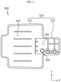
- FIG. 2 is a top view showing the appearance of the DIN-rail 300 according to an embodiment of the present disclosure.
- FIG. 3 is a front view showing the appearance of the DIN-rail 300 according to an embodiment of the present disclosure.
- FIG. 4 is a diagram showing an exemplary shape of a cross section cut along line A-A' in FIG. 1 .
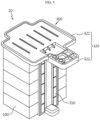
- FIG. 5 is a diagram schematically showing an electronic component assembly 20 including the DIN-rail 300 according to an embodiment of the present disclosure.
- the protection unit 320 may include a first portion 321 and a second portion 322.
- the first portion 321 is configured to cover the electronic component 100 and may be configured to collect fluid.
- the first portion 321 may have a shape that roughly corresponds to the shape of the upper part of the electronic component 100 so as to effectively cover the electronic component 100. In this case, when viewed from above according to the direction of gravity, the area of the first portion 321 may be larger than the area of the electronic component 100 so that the electronic component 100 is not exposed to the outside of the first portion 321.
- the second portion 322 extends from the first portion 321 to the outside of the electronic component 100 and may be configured to discharge the fluid collected by the first portion 321. Referring to FIGS. 2 and 5 , the second portion 322 may be formed to extend integrally with the first portion 321, for example. The second portion 322 may be configured so that the fluid collected in the first portion 321 is discharged in the direction of gravity from an extended end located opposite to the first portion 321 with respect to the body unit 310, for example.
- the electronic component 100 can be more effectively protected from physical external factors, and moisture caused by condensation caused by rapid changes in temperature or fluid containing such moisture can be collected and discharged more effectively.
- the first portion 321 may include a first collection space 330 that is embedded in a direction toward the electronic component 100.
- the first collection space 330 may be configured such that its internal area other than the perimeter of the first portion 321 is embedded.
- At least a portion of the bottom surface B of the first collection space 330 may have a downward sloping shape toward the second portion 322. That is, the bottom surface B of the first collection space 330 may include an inclined portion S that is inclined downward along the direction toward the second portion 322.
- the shape of the inclined portion S in the present disclosure is not limited to this, and the inclined portion S may have, for example, a shape in which the bottom surface B of the first collection space 330 is inclined downward along the direction from both ends of the Y-axis extending direction toward the center and also is simultaneously inclined downward in the direction toward the second portion (the positive direction of the X-axis).
- the second portion 322 may include a second collection space 340 configured to communicate with the first collection space 330.
- the second collection space 340 may be formed deeper than the first collection space 330. Due to the inclined shape of the bottom surface B of the first collection space 330, the fluid is collected, and the fluid may flow to the second collection space 340 by gravity and be collected again.
- a discharge hole 350 configured to discharge fluid may be formed in the bottom of the second collection space 340.
- the discharge hole 350 may be formed in an area corresponding to the opposite side of the electronic component based on the body unit 310.
- the fluid collected again in the second collection space 340 can be discharged through the discharge hole 350.
- the fluid discharged through the discharge hole 350 may not affect the electronic component during and after discharge.
- the fluid can be efficiently discharged by controlling the discharge direction and location of fluid through the discharge hole 350.
- the electronic component assembly 20 may include an electronic component 100 and the DIN-rail 300 according to the present disclosure.
- the electronic component 100 may be a circuit breaker.
- FIG. 6 is a diagram schematically showing an energy storage system 10 including the electronic component assembly 20 according to an embodiment of the present disclosure.
- the energy storage system 10 may include a battery pack including a plurality of secondary batteries, a heat sink 200 coupled to the battery pack and configured to cool the battery pack, and the above-described electronic component assembly 20 according to present disclosure.
- the electronic component assembly 20 included in the energy storage system 10 may be coupled to at least one of the battery pack and the heat sink 200. Additionally, the electronic component assembly 20 may be located lower than the heat sink 200 along the direction of gravity.
- the energy storage system 10 including the electronic component assembly 20 may include various other components included in the energy storage system in addition to the DIN-rail 10 or the electronic component assembly 20.
Landscapes
- Engineering & Computer Science (AREA)
- Chemical & Material Sciences (AREA)
- Chemical Kinetics & Catalysis (AREA)
- Electrochemistry (AREA)
- General Chemical & Material Sciences (AREA)
- Manufacturing & Machinery (AREA)
- Microelectronics & Electronic Packaging (AREA)
- Power Engineering (AREA)
- Casings For Electric Apparatus (AREA)
- Patch Boards (AREA)
- Distribution Board (AREA)
- Mounting Components In General For Electric Apparatus (AREA)
Abstract
Description
- The present disclosure relates to a DIN-rail, and an electronic component assembly and an energy storage system including the same. More specifically, the present disclosure relates to a DIN-rail for fixing electronic components, which may prevent deterioration of the insulation performance of electronic components by applying a structure capable of preventing condensation caused by rapid outdoor environmental changes and draining moisture, and an electronic component assembly and an energy storage system including the same.
- The present application claims priority to
Korean Patent Application No. 10-2022-0091541 filed on July 25, 2022 - Recently, as issues such as power shortage and eco-friendly energy have emerged, an energy storage system (ESS) for storing generated power has been receiving a lot of attention. Typically, using this energy storage system, it is easy to build a power management system such as a smart grid system, making it possible to easily control power supply in a specific region or city. In addition, as the commercialization of electric vehicles begins in earnest, this energy storage system can also be applied to electric charging stations where electric vehicles can be charged.
- The energy storage system may be configured in various forms, but may be typically configured to include one or more battery containers. At this time, the battery container may include a plurality of battery modules connected to each other in series and/or parallel. Here, the plurality of battery modules may be stored inside the battery container through a rack frame or a separate fixing structure. Since the energy storage system including a plurality of battery modules handles a very large amount of power, it essentially includes a circuit breaker that plays a role of protecting circuits and loads by blocking the line when a fault current such as overload, instantaneous current, or phase loss occurs on the electric line, and various electronic components are also included. These electronic components are coupled and fixed to a DIN-rail attached to a switchboard, etc.
- However, in existing energy storage systems, there was concern that the insulation performance of electronic components may be deteriorated due to environmental changes or condensation that occurs during the battery cooling process. Therefore, there is a need for a method that can maintain the insulation performance of electronic components and energy storage systems by preventing the inflow of moisture caused by condensation, etc.
- The present disclosure is designed to solve the problems of the related art, and therefore the present disclosure is directed to providing a DIN-rail for fixing electronic components, which may prevent the deterioration of the insulation performance of electronic components by applying a structure capable of preventing moisture from entering the electronic components and effectively draining the moisture even if condensation occurs due to, for example, rapid outdoor environmental changes.
- Another object of the present disclosure is to provide an electronic component assembly that can prevent deterioration of insulation performance by including this DIN-rail, and an energy storage system including the same.
- In order to accomplish the above object, a DIN-rail for fixing an electronic component according to an aspect of the present disclosure comprises a body unit disposed on one side of the electronic component and configured to be coupled with the electronic component; and a protection unit connected to the body unit, configured to cover the upper part of the electronic component, and configured to discharge fluid so that the fluid falling along the direction of gravity does not contact the electronic component.
- The protection unit may include a first portion configured to cover the electronic component and configured to collect the fluid; and a second portion configured to extend from the first portion to the outside of the electronic component and configured to discharge fluid collected by the first portion.
- When viewed from above along the direction of gravity, the area of the first portion may be larger than the area of the electronic component so that the electronic component is not exposed to the outside of the first portion.
- The first portion may have a first collection space with an embedded shape in a direction toward the electronic component.
- The bottom surface of the first collection space may have a downward sloping shape toward the second portion.
- The second portion may have a second collection space configured to communicate with the first collection space, and a discharge hole may be formed in the bottom surface of the second collection space to discharge the fluid.
- The second collection space may be formed deeper than the first collection space.
- The discharge hole may be formed in the area corresponding to the opposite side of the electronic component based on the body unit.
- The DIN-rail may contain a resin material.
- In order to accomplish another object, an electronic component assembly according to the present disclosure comprises the DIN-rail according to the present disclosure.
- The electronic component may be a circuit breaker.
- In order to accomplish another object, an energy storage system according to the present disclosure comprises the electronic component assembly according to the present disclosure.
- The energy storage system may comprise a battery pack including a plurality of secondary batteries; a heat sink coupled to the battery pack and configured to cool the battery pack; and the electronic component configured to collect and discharge fluid generated from the heat sink.
- The electronic component assembly may be coupled to at least one of the battery pack and the heat sink.
- The electronic component assembly may be located lower than the heat sink along the direction of gravity.
- According to one aspect of the present disclosure, in a DIN-rail that couples electronic components through a body unit, the electronic components can be protected from external physical factors by providing a protection unit. For example, it is possible to protect electronic components from moisture generated by condensation due to rapid changes in temperature, and prevent deterioration of the insulation performance of the electronic components by discharging moisture so that it does not come into contact with the electronic components.
- According to another aspect of the present disclosure, since the DIN-rail itself also has insulation performance, it is possible to more effectively prevent deterioration of the insulation performance of electronic components.
- According to still another aspect of the present disclosure, electronic components can be more effectively protected from physical external factors, and, for example, moisture resulting from condensation caused by rapid changes in temperature or fluid containing such moisture can be collected and discharged more effectively.
- According to still another aspect of the present disclosure, fluid discharged through the discharge hole may not affect electronic components during and after discharge. In other words, according to the present disclosure, efficient discharge of fluid is possible by controlling the discharge direction and location of fluid through the discharge hole.
- In addition, the present disclosure may have various other effects, and these will be explained in each embodiment, or the explanation will be omitted for effects that can be easily inferred by a person skilled in the art.
-
-
FIG. 1 is a perspective view showing the appearance of a DIN-rail according to an embodiment of the present disclosure. -
FIG. 2 is a top view showing the appearance of the DIN-rail according to an embodiment of the present disclosure. -
FIG. 3 is a front view showing the appearance of the DIN-rail according to an embodiment of the present disclosure. -
FIG. 4 is a diagram showing an exemplary shape of a cross section cut along line A-A' inFIG. 1 . -
FIG. 5 is a diagram schematically showing an electronic component assembly including the DIN-rail according to an embodiment of the present disclosure. -
FIG. 6 is a diagram schematically showing an energy storage system including the electronic component assembly according to an embodiment of the present disclosure. - Hereinafter, preferred embodiments of the present disclosure will be described in detail with reference to the accompanying drawings. The accompanying drawings illustrate a preferred embodiment of the present disclosure and together with the foregoing disclosure, serve to provide further understanding of the technical features of the present disclosure, and thus, the present disclosure is not construed as being limited to the drawings. Like reference numerals refer to like elements. Additionally, in the drawings, the thickness, proportions and dimensions of components are exaggerated for effective explanation of technical content.
- It should be understood that the terms used in the specification and the appended claims should not be construed as limited to general and dictionary meanings, but interpreted based on the meanings and concepts corresponding to technical aspects of the present disclosure on the basis of the principle that the inventor is allowed to define terms appropriately for the best explanation.
- In this specification, terms indicating directions such as up, down, left, right, front, and back are used, but it is obvious to those skilled in the art of the present disclosure that these terms are only for convenience of explanation and they may vary depending on the location of the target object or the location of the observer.
- Accordingly, the embodiments described in this specification and the configurations shown in the drawings are only one of the most preferred embodiments of the present disclosure and do not represent all technical details of the present disclosure, so it should be understood that there may be various equivalents and variations that can be replaced at the time of filing this application.
-
FIG. 1 is a perspective view showing the appearance of a DIN-rail 300 according to an embodiment of the present disclosure. - Referring to
FIG. 1 , the DIN-rail 300 for fixing electronic components according to an embodiment of the present disclosure includes abody unit 310 and aprotection unit 320. - The
body unit 310 may be disposed on one side of the electronic component and configured to be coupled with the electronic component. Although not shown in the drawing, a hook structure is provided on one side of thebody unit 310 and the electronic component, so that they can be coupled through the hook structure. However, the present disclosure is not limited to such a method of coupling thebody unit 310 and the electronic component, and they may be coupled by, for example, screws or bolts and nuts. - The
protection unit 320 is connected to thebody unit 310 and is configured to cover the upper part of the electronic component, and may be configured to discharge fluid so that the fluid falling along the direction of gravity cannot contact the electronic component. The fluid refers to a fluid that may cause problems such as a short circuit when coming into contact with an electronic component, and for example, it may be a fluid containing moisture. Theprotection unit 320 may have a substantially plate shape to cover the upper part of the electronic component. Theprotection unit 320 may be configured to cover the entire upper part of the electronic component. Theprotection unit 320 is equipped with an inclined structure or a discharge hole to discharge the fluid so that the fluid falling in the direction of gravity cannot contact the electronic component. However, the present disclosure does not limit the shape of theprotection unit 320. - According to this configuration in the present disclosure, in the DIN-
rail 300, which couples electronic components through thebody unit 310, the electronic components can be protected from external physical factors by providing theprotection unit 320. For example, it is possible to protect electronic components from condensation that occurs due to rapid changes in temperature, and prevent deterioration of the insulation performance of the electronic components by discharging moisture generated by the condensation so that it does not come into contact with the electronic components. - The DIN-
rail 300 may contain a resin material. In this case, since the DIN-rail 300 itself also has insulation performance, deterioration of the insulation performance of electronic components can be more effectively prevented. To maximize this effect, the DIN-rail 300 can be made of a resin material. -
FIG. 2 is a top view showing the appearance of the DIN-rail 300 according to an embodiment of the present disclosure.FIG. 3 is a front view showing the appearance of the DIN-rail 300 according to an embodiment of the present disclosure.FIG. 4 is a diagram showing an exemplary shape of a cross section cut along line A-A' inFIG. 1 .FIG. 5 is a diagram schematically showing anelectronic component assembly 20 including the DIN-rail 300 according to an embodiment of the present disclosure. - Referring to
FIG. 2 , theprotection unit 320 may include afirst portion 321 and asecond portion 322. - Referring to
FIGS. 2 and5 , thefirst portion 321 is configured to cover theelectronic component 100 and may be configured to collect fluid. Thefirst portion 321 may have a shape that roughly corresponds to the shape of the upper part of theelectronic component 100 so as to effectively cover theelectronic component 100. In this case, when viewed from above according to the direction of gravity, the area of thefirst portion 321 may be larger than the area of theelectronic component 100 so that theelectronic component 100 is not exposed to the outside of thefirst portion 321. - The
second portion 322 extends from thefirst portion 321 to the outside of theelectronic component 100 and may be configured to discharge the fluid collected by thefirst portion 321. Referring toFIGS. 2 and5 , thesecond portion 322 may be formed to extend integrally with thefirst portion 321, for example. Thesecond portion 322 may be configured so that the fluid collected in thefirst portion 321 is discharged in the direction of gravity from an extended end located opposite to thefirst portion 321 with respect to thebody unit 310, for example. - According to this configuration of the present disclosure, the
electronic component 100 can be more effectively protected from physical external factors, and moisture caused by condensation caused by rapid changes in temperature or fluid containing such moisture can be collected and discharged more effectively. - Referring to
FIGS. 2 to 5 , thefirst portion 321 may include afirst collection space 330 that is embedded in a direction toward theelectronic component 100. Thefirst collection space 330 may be configured such that its internal area other than the perimeter of thefirst portion 321 is embedded. At least a portion of the bottom surface B of thefirst collection space 330 may have a downward sloping shape toward thesecond portion 322. That is, the bottom surface B of thefirst collection space 330 may include an inclined portion S that is inclined downward along the direction toward thesecond portion 322. However, the shape of the inclined portion S in the present disclosure is not limited to this, and the inclined portion S may have, for example, a shape in which the bottom surface B of thefirst collection space 330 is inclined downward along the direction from both ends of the Y-axis extending direction toward the center and also is simultaneously inclined downward in the direction toward the second portion (the positive direction of the X-axis). - Referring to
FIGS. 2 to 4 , thesecond portion 322 may include asecond collection space 340 configured to communicate with thefirst collection space 330. Thesecond collection space 340 may be formed deeper than thefirst collection space 330. Due to the inclined shape of the bottom surface B of thefirst collection space 330, the fluid is collected, and the fluid may flow to thesecond collection space 340 by gravity and be collected again. - A
discharge hole 350 configured to discharge fluid may be formed in the bottom of thesecond collection space 340. Thedischarge hole 350 may be formed in an area corresponding to the opposite side of the electronic component based on thebody unit 310. The fluid collected again in thesecond collection space 340 can be discharged through thedischarge hole 350. - According to this configuration of the present disclosure, the fluid discharged through the
discharge hole 350 may not affect the electronic component during and after discharge. The fluid can be efficiently discharged by controlling the discharge direction and location of fluid through thedischarge hole 350. - Referring to
FIG. 5 , theelectronic component assembly 20 according to an embodiment of the present disclosure may include anelectronic component 100 and the DIN-rail 300 according to the present disclosure. In particular, theelectronic component 100 may be a circuit breaker. -
FIG. 6 is a diagram schematically showing anenergy storage system 10 including theelectronic component assembly 20 according to an embodiment of the present disclosure. - Referring to
FIG. 6 , theenergy storage system 10 according to an embodiment of the present disclosure may include a battery pack including a plurality of secondary batteries, aheat sink 200 coupled to the battery pack and configured to cool the battery pack, and the above-describedelectronic component assembly 20 according to present disclosure. - The
electronic component assembly 20 included in theenergy storage system 10 according to an embodiment of the present disclosure may be coupled to at least one of the battery pack and theheat sink 200. Additionally, theelectronic component assembly 20 may be located lower than theheat sink 200 along the direction of gravity. - As such, the
energy storage system 10 including theelectronic component assembly 20 according to this embodiment may include various other components included in the energy storage system in addition to the DIN-rail 10 or theelectronic component assembly 20. - As described above, the present disclosure has been described with a focus on preferred embodiments with reference to the accompanying drawings, but it is clear to those skilled in the art that many various obvious modifications can be made from this description without departing from the scope of the present disclosure. Accordingly, the scope of the present disclosure should be construed in terms of the appended claims to include such many modified examples.
-
- 10: energy storage system
- 20: electronic component assembly
- 100: electronic component
- 200: heat sink
- 300: DIN-rail
- 310: body unit
- 320: protection unit
- 321: first portion
- 322: second portion
- 330: first collection space
- 340: second collection space
- 350: discharge hole
- B: bottom surface
- S: inclined portion
Claims (14)
- A DIN-rail for fixing an electronic component, comprising:a body unit disposed on one side of the electronic component and configured to be coupled with the electronic component; anda protection unit connected to the body unit, configured to cover the upper part of the electronic component, and configured to discharge fluid so that the fluid falling along the direction of gravity does not contact the electronic component.
- The DIN-rail according to claim 1, wherein the protection unit includes:a first portion configured to cover the electronic component and configured to collect the fluid; anda second portion configured to extend from the first portion to the outside of the electronic component and configured to discharge fluid collected by the first portion.
- The DIN-rail according to claim 2, wherein when viewed from above along the direction of gravity, the area of the first portion is larger than the area of the electronic component so that the electronic component is not exposed to the outside of the first portion.
- The DIN-rail according to claim 2, wherein the first portion has a first collection space with an embedded shape in a direction toward the electronic component.
- The DIN-rail according to claim 4, wherein the bottom surface of the first collection space has a downward sloping shape toward the second portion.
- The DIN-rail according to claim 4, wherein the second portion has a second collection space configured to communicate with the first collection space, and
wherein a discharge hole is formed in the bottom surface of the second collection space to discharge the fluid. - The DIN-rail according to claim 6, wherein the second collection space is formed deeper than the first collection space.
- The DIN-rail according to claim 6, wherein the discharge hole is formed in the area corresponding to the opposite side of the electronic component based on the body unit.
- The DIN-rail according to claim 1, wherein the DIN-rail contains a resin material.
- An electronic component assembly, comprising:an electronic component; andthe DIN-rail according to any one of claims 1 to 9, which is coupled to the electronic component.
- The electronic component assembly according to claim 10, wherein the electronic component is a circuit breaker.
- An energy storage system, comprising:a battery pack including a plurality of secondary batteries;a heat sink coupled to the battery pack and configured to cool the battery pack; andthe electronic component assembly according to claim 10, which is configured to collect and discharge fluid generated from the heat sink.
- The energy storage system according to claim 12, wherein the electronic component assembly is coupled to at least one of the battery pack and the heat sink.
- The energy storage system according to claim 12, wherein the electronic component assembly is located lower than the heat sink along the direction of gravity.
Applications Claiming Priority (2)
| Application Number | Priority Date | Filing Date | Title |
|---|---|---|---|
| KR1020220091541A KR102941557B1 (en) | 2022-07-25 | 2022-07-25 | DIN rail, electronic components assembly and energy storage system comprising the same |
| PCT/KR2023/010681 WO2024025283A1 (en) | 2022-07-25 | 2023-07-24 | Din rail, electronic component assembly and energy storage system comprising same |
Publications (3)
| Publication Number | Publication Date |
|---|---|
| EP4429421A1 true EP4429421A1 (en) | 2024-09-11 |
| EP4429421A4 EP4429421A4 (en) | 2025-03-26 |
| EP4429421B1 EP4429421B1 (en) | 2025-12-17 |
Family
ID=89706867
Family Applications (1)
| Application Number | Title | Priority Date | Filing Date |
|---|---|---|---|
| EP23846942.3A Active EP4429421B1 (en) | 2022-07-25 | 2023-07-24 | Din-rail, and electronic component assembly and energy storage system including the same |
Country Status (9)
| Country | Link |
|---|---|
| US (1) | US20250329814A1 (en) |
| EP (1) | EP4429421B1 (en) |
| JP (1) | JP2025524117A (en) |
| KR (1) | KR102941557B1 (en) |
| CN (1) | CN118104406A (en) |
| AU (1) | AU2023313554A1 (en) |
| ES (1) | ES3058510T3 (en) |
| PL (1) | PL4429421T3 (en) |
| WO (1) | WO2024025283A1 (en) |
Family Cites Families (14)
| Publication number | Priority date | Publication date | Assignee | Title |
|---|---|---|---|---|
| FR2711858B1 (en) * | 1993-10-27 | 1995-12-15 | Merlin Gerin | Device for quick fixing of a support in an electrical equipment box. |
| DE29919130U1 (en) * | 1999-11-03 | 2001-03-08 | Weidmüller Interface GmbH & Co., 32760 Detmold | Termination device for modules that can be placed on a mounting rail |
| ITMI20070024A1 (en) * | 2007-01-10 | 2008-07-11 | Gewiss Spa | RAPID FIXING CONSTRUCTION SYSTEM WITH ELECTRIC PANEL OF ELECTRIC APPLIANCES |
| US9635783B2 (en) * | 2012-03-30 | 2017-04-25 | Sunpower Corporation | Electronic component housing with heat sink |
| KR102088974B1 (en) * | 2016-06-07 | 2020-03-13 | 주식회사 엘지화학 | Battery module, battery pack comprising the battery module and energy storage system comprising the battery pack |
| JP6691073B2 (en) * | 2017-04-25 | 2020-04-28 | 矢崎総業株式会社 | Electrical connection box and wire harness |
| JP6280274B1 (en) * | 2017-08-02 | 2018-02-14 | 東洋技研株式会社 | End protection cap |
| DE102017119466B4 (en) * | 2017-08-25 | 2022-06-09 | Dr. Ing. H.C. F. Porsche Aktiengesellschaft | Device for storing electrical energy for a motor vehicle |
| KR101987324B1 (en) * | 2017-09-28 | 2019-06-11 | 주식회사 케이디파워 | Inverter for solar power generation with heat dissipation and grounding function, distribution board, panel board, motor control panel, solar connection panel, ESS with heat dissipation and grounding function |
| JP6743098B2 (en) * | 2018-08-31 | 2020-08-19 | 本田技研工業株式会社 | Battery pack for electric vehicle |
| KR101976347B1 (en) * | 2018-10-10 | 2019-05-08 | 주식회사 삼신기전 | Integrated ESS enclosure |
| CN111916723B (en) | 2020-07-14 | 2021-08-17 | 蜂巢能源科技有限公司 | Gradient doped cobalt-free cathode material and preparation method thereof, as well as cathode for lithium ion battery and lithium battery |
| CN112186516A (en) * | 2020-08-24 | 2021-01-05 | 国网山东省电力公司惠民县供电公司 | Power cabinet for power engineering |
| CN213936898U (en) * | 2020-10-30 | 2021-08-10 | 南京协澳智能控制系统有限公司 | Compact installation module of electrical cabinet |
-
2022
- 2022-07-25 KR KR1020220091541A patent/KR102941557B1/en active Active
-
2023
- 2023-07-24 JP JP2025504353A patent/JP2025524117A/en active Pending
- 2023-07-24 PL PL23846942.3T patent/PL4429421T3/en unknown
- 2023-07-24 US US18/718,732 patent/US20250329814A1/en active Pending
- 2023-07-24 ES ES23846942T patent/ES3058510T3/en active Active
- 2023-07-24 WO PCT/KR2023/010681 patent/WO2024025283A1/en not_active Ceased
- 2023-07-24 EP EP23846942.3A patent/EP4429421B1/en active Active
- 2023-07-24 CN CN202380014228.3A patent/CN118104406A/en active Pending
- 2023-07-24 AU AU2023313554A patent/AU2023313554A1/en active Pending
Also Published As
| Publication number | Publication date |
|---|---|
| CN118104406A (en) | 2024-05-28 |
| PL4429421T3 (en) | 2026-03-16 |
| EP4429421B1 (en) | 2025-12-17 |
| ES3058510T3 (en) | 2026-03-11 |
| WO2024025283A1 (en) | 2024-02-01 |
| JP2025524117A (en) | 2025-07-25 |
| AU2023313554A1 (en) | 2024-08-01 |
| KR102941557B1 (en) | 2026-03-18 |
| US20250329814A1 (en) | 2025-10-23 |
| KR20240014165A (en) | 2024-02-01 |
| EP4429421A4 (en) | 2025-03-26 |
Similar Documents
| Publication | Publication Date | Title |
|---|---|---|
| EP3301738B1 (en) | Cell cover for secondary battery, and battery module comprising same | |
| EP3866252A1 (en) | Battery module and battery pack comprising same | |
| EP3331058B1 (en) | Electrical box for battery pack and battery pack structure using same | |
| EP3435440B1 (en) | Storage module for providing electrical energy comprising bordering module, arrangement and transport vehicle comprising the storage module | |
| US12548833B2 (en) | Battery module and battery pack comprising same | |
| EP4040565A1 (en) | Battery module, and electric vehicle and power storage device comprising battery module | |
| EP3920314B1 (en) | Battery pack and vehicle including same | |
| CN113875078A (en) | Battery module and battery pack including the same | |
| KR20170108970A (en) | Fully integrated portable power system based on photovoltaic cells | |
| WO2011084937A2 (en) | System and method for controlling voltage of individual battery cells within a battery pack | |
| US20250079548A1 (en) | Battery Module, and Battery Pack and Vehicle Comprising Same | |
| CN220627941U (en) | Condensed water protection device and battery pack | |
| EP4109649A1 (en) | Battery module and battery pack including same | |
| US20250329814A1 (en) | Din-rail, and electronic component assembly and energy storage system including the same | |
| EP4099488B1 (en) | Battery module and battery pack including the same | |
| CN213546443U (en) | A bracket for stacking and fixing of standard battery modules | |
| CN209913825U (en) | Highly integrated radio frequency spectrum monitoring device | |
| KR102711079B1 (en) | A component for a secondary battery with improved safty, and A battery module and battery pack comprising the same | |
| US20260106103A1 (en) | Circuit breaker and battery control system including the circuit breaker | |
| CN217158576U (en) | Soft package battery pack | |
| KR102963835B1 (en) | Battery module and battery pack including the same | |
| CN222233699U (en) | Battery and battery system | |
| US20230043832A1 (en) | Battery module and battery pack including the same | |
| CN221783349U (en) | A layered battery pack system | |
| KR20260006774A (en) | Protective switchboards in energy storage systems |
Legal Events
| Date | Code | Title | Description |
|---|---|---|---|
| STAA | Information on the status of an ep patent application or granted ep patent |
Free format text: STATUS: THE INTERNATIONAL PUBLICATION HAS BEEN MADE |
|
| PUAI | Public reference made under article 153(3) epc to a published international application that has entered the european phase |
Free format text: ORIGINAL CODE: 0009012 |
|
| STAA | Information on the status of an ep patent application or granted ep patent |
Free format text: STATUS: REQUEST FOR EXAMINATION WAS MADE |
|
| 17P | Request for examination filed |
Effective date: 20240607 |
|
| AK | Designated contracting states |
Kind code of ref document: A1 Designated state(s): AL AT BE BG CH CY CZ DE DK EE ES FI FR GB GR HR HU IE IS IT LI LT LU LV MC ME MK MT NL NO PL PT RO RS SE SI SK SM TR |
|
| A4 | Supplementary search report drawn up and despatched |
Effective date: 20250225 |
|
| RIC1 | Information provided on ipc code assigned before grant |
Ipc: H02B 1/28 20060101ALN20250219BHEP Ipc: H02B 1/052 20060101ALI20250219BHEP Ipc: H01M 10/627 20140101ALI20250219BHEP Ipc: H01M 10/6551 20140101ALI20250219BHEP Ipc: H01M 50/691 20210101ALI20250219BHEP Ipc: H05K 5/02 20060101ALI20250219BHEP Ipc: H05K 7/12 20060101AFI20250219BHEP |
|
| REG | Reference to a national code |
Ref country code: DE Ref legal event code: R079 Ipc: H05K0005020000 Ref country code: DE Ref legal event code: R079 Ref document number: 602023009924 Country of ref document: DE Free format text: PREVIOUS MAIN CLASS: H05K0007120000 Ipc: H05K0005020000 |
|
| GRAP | Despatch of communication of intention to grant a patent |
Free format text: ORIGINAL CODE: EPIDOSNIGR1 |
|
| STAA | Information on the status of an ep patent application or granted ep patent |
Free format text: STATUS: GRANT OF PATENT IS INTENDED |
|
| RIC1 | Information provided on ipc code assigned before grant |
Ipc: H05K 5/02 20060101AFI20250801BHEP Ipc: H01M 50/691 20210101ALI20250801BHEP Ipc: H01M 10/6551 20140101ALI20250801BHEP Ipc: H01M 10/627 20140101ALI20250801BHEP Ipc: H02B 1/052 20060101ALI20250801BHEP Ipc: H02B 1/28 20060101ALN20250801BHEP |
|
| DAV | Request for validation of the european patent (deleted) | ||
| DAX | Request for extension of the european patent (deleted) | ||
| INTG | Intention to grant announced |
Effective date: 20250820 |
|
| P01 | Opt-out of the competence of the unified patent court (upc) registered |
Free format text: CASE NUMBER: UPC_APP_6783_4429421/2025 Effective date: 20250911 |
|
| GRAS | Grant fee paid |
Free format text: ORIGINAL CODE: EPIDOSNIGR3 |
|
| GRAA | (expected) grant |
Free format text: ORIGINAL CODE: 0009210 |
|
| STAA | Information on the status of an ep patent application or granted ep patent |
Free format text: STATUS: THE PATENT HAS BEEN GRANTED |
|
| AK | Designated contracting states |
Kind code of ref document: B1 Designated state(s): AL AT BE BG CH CY CZ DE DK EE ES FI FR GB GR HR HU IE IS IT LI LT LU LV MC ME MK MT NL NO PL PT RO RS SE SI SK SM TR |
|
| REG | Reference to a national code |
Ref country code: CH Ref legal event code: F10 Free format text: ST27 STATUS EVENT CODE: U-0-0-F10-F00 (AS PROVIDED BY THE NATIONAL OFFICE) Effective date: 20251217 Ref country code: GB Ref legal event code: FG4D |
|
| REG | Reference to a national code |
Ref country code: DE Ref legal event code: R096 Ref document number: 602023009924 Country of ref document: DE |
|
| REG | Reference to a national code |
Ref country code: SE Ref legal event code: TRGR |
|
| REG | Reference to a national code |
Ref country code: ES Ref legal event code: FG2A Ref document number: 3058510 Country of ref document: ES Kind code of ref document: T3 Effective date: 20260311 |
|
| REG | Reference to a national code |
Ref country code: LT Ref legal event code: MG9D |
|
| PG25 | Lapsed in a contracting state [announced via postgrant information from national office to epo] |
Ref country code: NO Free format text: LAPSE BECAUSE OF FAILURE TO SUBMIT A TRANSLATION OF THE DESCRIPTION OR TO PAY THE FEE WITHIN THE PRESCRIBED TIME-LIMIT Effective date: 20260317 |
|
| PG25 | Lapsed in a contracting state [announced via postgrant information from national office to epo] |
Ref country code: FI Free format text: LAPSE BECAUSE OF FAILURE TO SUBMIT A TRANSLATION OF THE DESCRIPTION OR TO PAY THE FEE WITHIN THE PRESCRIBED TIME-LIMIT Effective date: 20251217 Ref country code: HR Free format text: LAPSE BECAUSE OF FAILURE TO SUBMIT A TRANSLATION OF THE DESCRIPTION OR TO PAY THE FEE WITHIN THE PRESCRIBED TIME-LIMIT Effective date: 20251217 |
|
| PG25 | Lapsed in a contracting state [announced via postgrant information from national office to epo] |
Ref country code: RS Free format text: LAPSE BECAUSE OF FAILURE TO SUBMIT A TRANSLATION OF THE DESCRIPTION OR TO PAY THE FEE WITHIN THE PRESCRIBED TIME-LIMIT Effective date: 20260317 |
|
| REG | Reference to a national code |
Ref country code: NL Ref legal event code: MP Effective date: 20251217 |
|
| PG25 | Lapsed in a contracting state [announced via postgrant information from national office to epo] |
Ref country code: LV Free format text: LAPSE BECAUSE OF FAILURE TO SUBMIT A TRANSLATION OF THE DESCRIPTION OR TO PAY THE FEE WITHIN THE PRESCRIBED TIME-LIMIT Effective date: 20251217 |
|
| PG25 | Lapsed in a contracting state [announced via postgrant information from national office to epo] |
Ref country code: BG Free format text: LAPSE BECAUSE OF FAILURE TO SUBMIT A TRANSLATION OF THE DESCRIPTION OR TO PAY THE FEE WITHIN THE PRESCRIBED TIME-LIMIT Effective date: 20251217 |