EP3301738B1 - Cell cover for secondary battery, and battery module comprising same - Google Patents
Cell cover for secondary battery, and battery module comprising same Download PDFInfo
- Publication number
- EP3301738B1 EP3301738B1 EP16811902.2A EP16811902A EP3301738B1 EP 3301738 B1 EP3301738 B1 EP 3301738B1 EP 16811902 A EP16811902 A EP 16811902A EP 3301738 B1 EP3301738 B1 EP 3301738B1
- Authority
- EP
- European Patent Office
- Prior art keywords
- plate
- bottom plate
- cell cover
- side plate
- support member
- Prior art date
- Legal status (The legal status is an assumption and is not a legal conclusion. Google has not performed a legal analysis and makes no representation as to the accuracy of the status listed.)
- Active
Links
Images


Classifications
-
- H—ELECTRICITY
- H01—ELECTRIC ELEMENTS
- H01M—PROCESSES OR MEANS, e.g. BATTERIES, FOR THE DIRECT CONVERSION OF CHEMICAL ENERGY INTO ELECTRICAL ENERGY
- H01M10/00—Secondary cells; Manufacture thereof
- H01M10/60—Heating or cooling; Temperature control
- H01M10/65—Means for temperature control structurally associated with the cells
- H01M10/655—Solid structures for heat exchange or heat conduction
- H01M10/6556—Solid parts with flow channel passages or pipes for heat exchange
-
- H—ELECTRICITY
- H01—ELECTRIC ELEMENTS
- H01M—PROCESSES OR MEANS, e.g. BATTERIES, FOR THE DIRECT CONVERSION OF CHEMICAL ENERGY INTO ELECTRICAL ENERGY
- H01M10/00—Secondary cells; Manufacture thereof
- H01M10/60—Heating or cooling; Temperature control
- H01M10/61—Types of temperature control
- H01M10/613—Cooling or keeping cold
-
- H—ELECTRICITY
- H01—ELECTRIC ELEMENTS
- H01M—PROCESSES OR MEANS, e.g. BATTERIES, FOR THE DIRECT CONVERSION OF CHEMICAL ENERGY INTO ELECTRICAL ENERGY
- H01M10/00—Secondary cells; Manufacture thereof
- H01M10/60—Heating or cooling; Temperature control
- H01M10/62—Heating or cooling; Temperature control specially adapted for specific applications
- H01M10/625—Vehicles
-
- H—ELECTRICITY
- H01—ELECTRIC ELEMENTS
- H01M—PROCESSES OR MEANS, e.g. BATTERIES, FOR THE DIRECT CONVERSION OF CHEMICAL ENERGY INTO ELECTRICAL ENERGY
- H01M10/00—Secondary cells; Manufacture thereof
- H01M10/60—Heating or cooling; Temperature control
- H01M10/64—Heating or cooling; Temperature control characterised by the shape of the cells
- H01M10/647—Prismatic or flat cells, e.g. pouch cells
-
- H—ELECTRICITY
- H01—ELECTRIC ELEMENTS
- H01M—PROCESSES OR MEANS, e.g. BATTERIES, FOR THE DIRECT CONVERSION OF CHEMICAL ENERGY INTO ELECTRICAL ENERGY
- H01M10/00—Secondary cells; Manufacture thereof
- H01M10/60—Heating or cooling; Temperature control
- H01M10/65—Means for temperature control structurally associated with the cells
- H01M10/655—Solid structures for heat exchange or heat conduction
- H01M10/6551—Surfaces specially adapted for heat dissipation or radiation, e.g. fins or coatings
-
- H—ELECTRICITY
- H01—ELECTRIC ELEMENTS
- H01M—PROCESSES OR MEANS, e.g. BATTERIES, FOR THE DIRECT CONVERSION OF CHEMICAL ENERGY INTO ELECTRICAL ENERGY
- H01M10/00—Secondary cells; Manufacture thereof
- H01M10/60—Heating or cooling; Temperature control
- H01M10/65—Means for temperature control structurally associated with the cells
- H01M10/655—Solid structures for heat exchange or heat conduction
- H01M10/6554—Rods or plates
- H01M10/6555—Rods or plates arranged between the cells
-
- H—ELECTRICITY
- H01—ELECTRIC ELEMENTS
- H01M—PROCESSES OR MEANS, e.g. BATTERIES, FOR THE DIRECT CONVERSION OF CHEMICAL ENERGY INTO ELECTRICAL ENERGY
- H01M50/00—Constructional details or processes of manufacture of the non-active parts of electrochemical cells other than fuel cells, e.g. hybrid cells
- H01M50/20—Mountings; Secondary casings or frames; Racks, modules or packs; Suspension devices; Shock absorbers; Transport or carrying devices; Holders
- H01M50/204—Racks, modules or packs for multiple batteries or multiple cells
- H01M50/207—Racks, modules or packs for multiple batteries or multiple cells characterised by their shape
- H01M50/211—Racks, modules or packs for multiple batteries or multiple cells characterised by their shape adapted for pouch cells
-
- H—ELECTRICITY
- H01—ELECTRIC ELEMENTS
- H01M—PROCESSES OR MEANS, e.g. BATTERIES, FOR THE DIRECT CONVERSION OF CHEMICAL ENERGY INTO ELECTRICAL ENERGY
- H01M50/00—Constructional details or processes of manufacture of the non-active parts of electrochemical cells other than fuel cells, e.g. hybrid cells
- H01M50/20—Mountings; Secondary casings or frames; Racks, modules or packs; Suspension devices; Shock absorbers; Transport or carrying devices; Holders
- H01M50/218—Mountings; Secondary casings or frames; Racks, modules or packs; Suspension devices; Shock absorbers; Transport or carrying devices; Holders characterised by the material
- H01M50/22—Mountings; Secondary casings or frames; Racks, modules or packs; Suspension devices; Shock absorbers; Transport or carrying devices; Holders characterised by the material of the casings or racks
- H01M50/222—Inorganic material
- H01M50/224—Metals
-
- H—ELECTRICITY
- H01—ELECTRIC ELEMENTS
- H01M—PROCESSES OR MEANS, e.g. BATTERIES, FOR THE DIRECT CONVERSION OF CHEMICAL ENERGY INTO ELECTRICAL ENERGY
- H01M50/00—Constructional details or processes of manufacture of the non-active parts of electrochemical cells other than fuel cells, e.g. hybrid cells
- H01M50/20—Mountings; Secondary casings or frames; Racks, modules or packs; Suspension devices; Shock absorbers; Transport or carrying devices; Holders
- H01M50/271—Lids or covers for the racks or secondary casings
- H01M50/273—Lids or covers for the racks or secondary casings characterised by the material
- H01M50/276—Inorganic material
-
- H—ELECTRICITY
- H01—ELECTRIC ELEMENTS
- H01M—PROCESSES OR MEANS, e.g. BATTERIES, FOR THE DIRECT CONVERSION OF CHEMICAL ENERGY INTO ELECTRICAL ENERGY
- H01M2220/00—Batteries for particular applications
- H01M2220/20—Batteries in motive systems, e.g. vehicle, ship, plane
-
- Y—GENERAL TAGGING OF NEW TECHNOLOGICAL DEVELOPMENTS; GENERAL TAGGING OF CROSS-SECTIONAL TECHNOLOGIES SPANNING OVER SEVERAL SECTIONS OF THE IPC; TECHNICAL SUBJECTS COVERED BY FORMER USPC CROSS-REFERENCE ART COLLECTIONS [XRACs] AND DIGESTS
- Y02—TECHNOLOGIES OR APPLICATIONS FOR MITIGATION OR ADAPTATION AGAINST CLIMATE CHANGE
- Y02E—REDUCTION OF GREENHOUSE GAS [GHG] EMISSIONS, RELATED TO ENERGY GENERATION, TRANSMISSION OR DISTRIBUTION
- Y02E60/00—Enabling technologies; Technologies with a potential or indirect contribution to GHG emissions mitigation
- Y02E60/10—Energy storage using batteries
Definitions
- the present disclosure relates to a cell cover for a secondary battery, and more particularly, to a cell cover for a secondary battery, which accommodates a secondary battery therein to protect the secondary battery and guides stacking of secondary batteries, and a battery module including the cell cover.
- Secondary batteries commercially used at the present include nickel-cadmium batteries, nickel-hydrogen batteries, nickel-zinc batteries, lithium secondary batteries or the like, among which the lithium secondary batteries are in the limelight due to their very low self-discharge rate, high energy density, and free charging/discharging since a memory effect does not substantially occur in comparison to nickel-based secondary batteries.
- Such a lithium secondary battery mainly uses lithium-based oxide and a carbon material as a cathode active material and an anode active material, respectively.
- the lithium secondary battery includes an electrode assembly, which includes a cathode plate coated with the cathode active material, an anode plate coated with the anode active material, and a separator interposed therebetween, and an outer casing, i.e., a battery case, to accommodate with a hermetic seal the electrode assembly therein along with an electrolyte solution.
- lithium secondary batteries may be classified, depending on a shape of a battery casing, into can shaped secondary batteries in which an electrode assembly is embedded in a metal casing and pouch-type secondary batteries in which an electrode assembly is embedded in a pouch of an aluminum laminate sheet.
- the electric vehicles include a hybrid vehicle, a plug-in hybrid vehicle, a purely electric vehicle powered by only an electric motor and a battery without an internal combustion engine, and so forth.
- a number of secondary batteries are electrically connected to increase capacity and output.
- a pouch-type secondary battery is mostly used due to its easy stacking.
- the pouch-type secondary battery does not have high mechanical strength because it is generally packed with a battery case including a laminate sheet of aluminum and polymer resin.
- a cell cover is used to protect the secondary batteries from an external shock, etc., to prevent movement of the secondary batteries, and to facilitate stacking of the secondary batteries. Examples of battery cases can be found for instance in EP 1278263 , WO 2014/035160 , DE 10 2012 101141 and DE 10 2011 004033 .
- the secondary battery may undergo performance deterioration, and in the worst case, may explode or catch fire.
- the temperature of the battery module may rise more quickly and drastically due to buildup of heat produced from the multiple secondary batteries in a small space.
- a battery module included in a vehicle battery pack is likely to be often exposed to direct sunlight and to be in a high-temperature condition such as the summer season, a desert region, or the like.
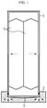
- FIG. 1 illustrates a contact structure between a cell cover and a cooling plate and a heat transfer path according to a related art.
- a conventional battery module accommodates a secondary battery B and includes a cell cover 1 and a cooling plate 2 supporting the cell cover 1.
- the cooling plate 2 in the shape of an uneven plate includes a groove 3 on a top surface thereof, and the cell cover 1 is mounted in the groove 3.
- a heat sink may be positioned under the cooling plate 2. Heat generated in the secondary battery B is transferred to the cooling plate 2 along a plate surface of the cell cover 1, and heat absorbed by the cooling plate 2 is transferred to the heat sink.
- the heat sink may be cooled by a coolant flowing along an internal flow path.
- the present disclosure is designed to solve the problems of the related art, and therefore the present disclosure is directed to providing a cell cover capable of closely contacting a cooling plate having a tolerance.
- a battery module comprising a cell cover for a secondary battery, which accommodates at least one secondary battery in an internal space thereof and is mounted in a groove formed on a top surface of a cooling plate having an uneven plate shape, the cell cover including a first side plate and a second side plate facing each other to form opposite side surfaces of the internal space, a top plate forming a top surface of the internal space and connecting upper edges of the first side plate and the second side plate, wherein the top plate of the cell cover comprises a first top plate extending from an upper edge of the first side plate and a second top plate extending from an upper edge of the second side plate to face the first top plate, and the first top plate and the second top plate are detachably coupled to each other, wherein the first top plate and the second top plate include hooks and hook engagement holes, respectively, configured to be engaged with each other in a hooking manner, and a first bottom plate extending from a lower edge of the first side plate and a second bottom plate extending from a
- the first bottom plate and the second bottom plate are in an inclined shape, an end portion of the first bottom plate and an end portion of the second bottom plate is spaced apart from each other.
- the first bottom plate and the second bottom plate may include a flexible material to be changed in shape according to a shape of the groove when the first bottom plate and the second bottom plate are mounted in the groove.
- At least one of the first bottom plate and the second bottom plate may include at least one cut portion that is cut in parallel with a widthwise direction of the groove.
- the cell cover may further include a support member placed in the internal space to support the first side plate and the second side plate to maintain an interval between the first side plate and the second side plate.
- the support member may include an upper support member placed to contact a bottom surface of the top plate and a lower support member placed above the first bottom plate and the second bottom plate to face the upper support member.
- a vehicle including the above-described battery module.
- the vehicle may be any one of an electric vehicle, a hybrid electric vehicle, and a plug-in hybrid electric vehicle.
- a cell cover capable of closely contacting a cooling plate having a tolerance is provided. Therefore, heat transfer between the cell cover and the cooling plate is facilitated, thereby improving the cooling efficiency of the battery cell.
- a contact area between the cell cover and the cooling plate is sufficiently secured, thus removing a need to use an additional component such as a thermal interface material (TIM) and thus reducing a unit cost of production of a product.
- TIM thermal interface material
- a cell cover for a secondary battery is used when a battery module is configured by stacking and packing one or more secondary batteries, and refers to a component that prevents movement of a secondary battery by holding the secondary battery and is stacked with another cell cover to guide assembly of secondary batteries.
- a secondary battery cell cover 10 includes a metal material such as aluminum, etc., and has an internal space in the shape of a box that is approximately rectangular parallelepiped to accommodate a secondary battery B therein.
- the secondary battery B may be a pouch-type secondary battery.
- the pouch-type secondary battery has low mechanical strength because an outer casing thereof includes a metal layer and a resin layer, whereas the cell cover 10 makes up for such a mechanical strength of the pouch-type secondary battery.
- the secondary battery cell cover 10 absorbs heat produced from the secondary battery B and radiates the heat to outside.
- the secondary battery cell cover 10 according to the present disclosure is designed to minimize thermal contact resistance with respect to a cooling plate 20 having an uneven surface due to tolerance. This will be described in detail with reference to FIGS. 2 through 4 .
- FIG. 2 is a perspective view of a cell cover according to an embodiment of the present disclosure
- FIG. 3 is an exploded perspective view of FIG. 2
- FIG. 4 is a perspective view of a cell cover of FIG. 2 , when viewed from the bottom.
- the secondary battery cell cover 10 has an approximately rectangular parallelepiped shape in which a front surface and a back surface are open and an internal space is provided. That is, the secondary battery cell cover 10 includes a first side plate 110 and a second side plate 210 that face each other to form opposite side surfaces of the internal space, top plates 120 and 220 that form a top surface of the internal space and connect upper edges of the first side plate 110 and the second side plate 210, respectively, and bottom plates 130 and 230 that form a bottom surface of the internal space.
- the top plates 120 and 220 includes a first top plate 120 and a second top plate 220.
- the first top plate 120 and the second top plate 220 includes hooks 121 and hook engagement holes 221, respectively, which are engaged with each other in a hooking manner.
- the bottom plates 130 and 230 include a first bottom plate 130 and a second bottom plate 230.
- the first bottom plate 130 extends from lower edges of the first side plate 110
- the second bottom plate 230 extends from lower edges of the second side plate 210 to face the first bottom plate 130.
- the first bottom plate 130 and the second bottom plate 230 are inclined downwardly at an angle with respect to a horizontal plane, respectively, and end portions thereof are spaced apart from each other.
- the first bottom plate 130 and the second bottom plate 230 will be described in more detail later for convenience.
- the first side plate 110, the second side plate 210, the top plates 120 and 220, and the bottom plates 130 and 230 are conceptually divided elements, and all or some of them may be mutually assembled or integrally molded.
- the secondary battery cell cover 10 includes a first unit cell cover 100 and a second unit cell cover 200 as shown in FIG. 3 .
- the first unit cell cover 100 and the second unit cell cover 200 are integrally formed.
- the first unit cell cover 100 includes the first top plate 120, the first side plate 110, and the first bottom plate 130, which are integrated thereinto
- the second unit cell cover 200 includes the second top plate 220, the second side plate 210, and the second bottom plate 230, which are integrated thereinto.
- the first unit cell cover 100 and the second unit cell cover 200 are detachably coupled to each other by engaging the first top plate 120 and the second top plate 220 with each other in the hooking manner.
- the secondary battery B may be densely disposed in the internal space of the secondary battery cell cover 10. That is, the secondary battery B may be disposed and fixed such that a surface of an outer casing contacts the first side plate 110 or the second side plate 210. An electrode lead portion may be exposed to outside through the open front surface or back surface of the cell cover 10. By interconnecting electrode leads exposed to outside through a bus bar (not shown), secondary battery B cells may be connected in series or in parallel.
- secondary batteries B are settled such that they are overlapped on each other one by one in the first unit cell cover 100, and then the second unit cell cover 200 is covered with the first unit cell cover 100, and the hooks 121 of the first top plate 120 and the second top plate 220 are engaged with each other, thus accommodating two secondary batteries B in the internal space of the cell cover 10.
- FIG. 5 is a perspective view schematically showing that the cell cover 10 according to an embodiment of the present disclosure is mounted on the cooling plate 20, and FIG. 6 illustrates a contact structure between a cell cover and a cooling plate and a heat transfer path according an embodiment of the present disclosure, and FIG. 6 illustrates a contact structure between the cell cover 10 and the cooling plate 20 and a heat transfer path according an embodiment of the present disclosure.
- the secondary battery cell cover 10 is mounted on the cooling plate 20.
- the cooling plate 20 includes a plurality of grooves 21 on a top surface thereof in the shape of an uneven plate to support a plurality of cell covers 10 on an upper portion thereof.
- the cooling plate 20 includes a thermally conductive metal plate to absorb heat of the cell covers 10.
- a heat sink (not shown) may be positioned under the cooling plate 20. The heat sink means an object that absorbs and radiates heat from another object by thermal contact.
- the heat sink may include a hollow structure having an internal flow path through which a refrigerant such as a coolant, cooling gas, air, etc.
- a refrigerant such as a coolant, cooling gas, air, etc.
- the secondary battery cell cover 10 is provided such that the first bottom plate 130 and the second bottom plate 230 are inclined downwardly at an angle with respect to the horizontal plane, as shown in FIGS. 2 , 4 , and 6 .
- the angle may be determined based on an average shape of the groove 21 due to tolerance in manufacturing of the cooling plate 20.
- the first bottom plate 130 and the second bottom plate 230 unlike the top plates 120 and 220, are separated from each other such that an end portion E1 of the first bottom plate 130 and an end portion E2 of the second bottom plate 230 are spaced apart from each other.
- the cell cover 10 including the first bottom plate 130 and the second bottom plate 230 may include an aluminum material that has high heat conductivity and is flexible.
- the first bottom plate 130 and the second bottom plate 230 may be changed in shape according to the shape of the groove 21.
- the first bottom plate 130 and the second bottom plate 230 may closely contact the surface of the groove 21 due to their flexibility. That is, as the first bottom plate 130 and the second bottom plate 230 are hit against the flat surface of the groove 21 and are folded, the inclined shape of the first bottom plate 130 and the second bottom plate 230 may be changed to a flat shape.
- first bottom plate 130 may be folded in a counterclockwise direction axially along the lower edge of the first side plate 110 and the second bottom plate 230 is folded in a clockwise direction axially along the lower edge of the second side plate 210, such that the first bottom plate 130 and the second bottom plate 230 closely contact the surface of the groove 21.
- heat may be transferred without a gap on the bottom surface of the cell cover 10.
- the groove 21 of the cooling plate 20 may have an uneven surface that is gently concave or convex due to tolerance.
- the cell cover 10 according to the current embodiment is mounted such that the bottom surface of the cell cover 10 is in closely contact with the groove 21 of the cooling plate 20 having such tolerance. That is, referring to (b) of FIG. 6 , in spite of the groove 21 of the slightly concave surface, when the cell cover 10 is completely inserted into the groove 21, the inclined shape of the first bottom plate 130 and the second bottom plate 230 are not changed to the extent more than the first bottom plate 130 and the second bottom plate 230 contact the concave surface of the groove 21. Thus, the bottom plates 130 and 230 of the cell cover 10 contacts the groove 21 of the cooling plate 20 as closely as possible.
- the first bottom plate 130 and the second bottom plate 230 is changed in shape to closely contact the convex surface of the groove 21, and thus, also in this case, the bottom plates 130 and 230 of the cell cover 10 closely contacts the surface of the groove 21.
- the bottom plates 130 and 230 are inclined downwardly at an angle with respect to the horizontal plane, such that the bottom plates 130 and 230, even when assembled with the cooling plate 20 including the groove 21 having an uneven surface due to tolerance, may be flexibly changed in shape.
- a contact resistance between the cell cover 10 and the cooling plate 20 is significantly reduced.
- a thermal contact resistance enhancement member such as a thermal interface material (TIM), etc.
- TIM thermal interface material
- the secondary battery cell cover 10 may further include a support member 300 in the internal space to support the first side plate 110 and the second side plate 210 such that an interval between the first side plate 110 and the second side plate 210 is maintained constant.
- the support member 300 may be a plate of a plastic material having high mechanical strength.
- the scope of the present disclosure is not limited to the foregoing example. That is, the support member 300 is not specially limited in shape or material as long as the support member 300 maintains the shape of the cell cover 10.
- the support member 310 and 320 reinforces the mechanical strength of the first unit cell cover 100 and the second unit cell cover 200 of an aluminum material and absorbs an external shock, thus preventing the interval between the first side plate 110 and the second side plate 210 from being narrowed.
- the support member 300 may also support the first side plate 110 and the second side plate 210 to prevent the cell cover 10 absorbing heat from being easily changed in shape. As the internal space of the cell cover 10 is maintained constant, the secondary batteries B may be stably protected.
- the support member 300 may include an upper support member 310 placed to contact the bottom surfaces of the top plates 120 and 220 and a lower support member 320 placed above the first bottom plate 130 and the second bottom plate 230.
- the upper support member 310 is placed to contact three surfaces of the first and second side plates 110 and 210 and the top plates 120 and 220 to support the top plates 120 and 220 as well as to maintain the interval between the first and second side plates 110 and 210.
- the lower support member 320 is placed under the upper support member 310 having the secondary batteries B therebetween.
- the lower support member 320 is placed on lower edge regions of the first and second side plates 110 and 210.
- the lower support member 320 may guide horizontal folding of the first bottom plate 130 and the second bottom plate 230 when the cell cover 10 is inserted into the flat surface of the groove 21. That is, in the current embodiment, a folding angle of the first bottom plate 130 and the second bottom plate 230 is limited by the lower support member 320.
- a position of the lower support member 320 may be changed not to limit the folding angle of the first bottom plate 130 and the second bottom plate 230.
- the lower support member 320 may be placed higher than shown in FIG. 6 considering the folding angle of the first bottom plate 130 and the second bottom plate 230.
- FIG. 4 Another embodiment of the present disclosure to be described below corresponds to FIG. 4 when compared to the previous embodiment.
- Like reference numerals refer to like members, and a repeated description of identical members will not be avoided.
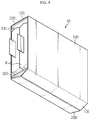
- FIG. 7 is a perspective view of a cell cover 10' according to another embodiment of the present disclosure, when viewed from the bottom.
- the current embodiment is similar to the previous embodiment except for a bottom plate, and thus the following description will focus on a difference from the previous embodiment.
- bottom plates 130' and 230' of the cell cover 10' are structured, like in the previous embodiment, such that the first bottom plate 130' and the second bottom plate 230' are separated from each other and inclined, but the first bottom plate 130' and the second bottom plate 230' further include at least one cut portions S being cut in parallel with the widthwise direction of the groove 21 of the cooling plate 20.
- the first bottom plate 130' and the second bottom plate 230' are cut into several regions, such that when the cell cover 10' is mounted in the groove 21, the first bottom plate 130' and the second bottom plate 230' may be separately changed in shape from cut unit region to cut unit region according to an undulating or uneven shape of the groove 21.
- the groove 21 of the cooling plate 20 may have a longitudinally undulating surface due to tolerance.
- the cell cover 10' according to the current embodiment may effectively contact, especially, the undulating groove 21.
- a gap between the bottom plates 130' and 230' and the surface of the groove 21 may be reduced and a contact area therebetween may increase when compared to a case where the first bottom plate 130' and the second bottom plate 230' are changed in shape together.
- the contact area between the cell cover 10' and the cooling plate 20 may be sufficiently secured, increasing a heat transfer rate and thus improving cooling efficiency.
- the battery module according to the present disclosure includes the above-described secondary battery cell cover and cooling plate according to the present disclosure.
- the battery module may further include not only the secondary battery cell cover and the cooling plate, but a case for covering them and various devices for controlling charging/discharging secondary batteries, such as a battery management system (BMS), an electric current sensor, a fuse, etc.
- BMS battery management system
- the battery module according to the present disclosure is applied to a vehicle such as an electric vehicle or a hybrid vehicle. That is, a vehicle according to the present disclosure includes the battery module according to the present disclosure.
Description
- The present disclosure relates to a cell cover for a secondary battery, and more particularly, to a cell cover for a secondary battery, which accommodates a secondary battery therein to protect the secondary battery and guides stacking of secondary batteries, and a battery module including the cell cover.
- Secondary batteries commercially used at the present include nickel-cadmium batteries, nickel-hydrogen batteries, nickel-zinc batteries, lithium secondary batteries or the like, among which the lithium secondary batteries are in the limelight due to their very low self-discharge rate, high energy density, and free charging/discharging since a memory effect does not substantially occur in comparison to nickel-based secondary batteries.
- Such a lithium secondary battery mainly uses lithium-based oxide and a carbon material as a cathode active material and an anode active material, respectively. The lithium secondary battery includes an electrode assembly, which includes a cathode plate coated with the cathode active material, an anode plate coated with the anode active material, and a separator interposed therebetween, and an outer casing, i.e., a battery case, to accommodate with a hermetic seal the electrode assembly therein along with an electrolyte solution.
- Generally, lithium secondary batteries may be classified, depending on a shape of a battery casing, into can shaped secondary batteries in which an electrode assembly is embedded in a metal casing and pouch-type secondary batteries in which an electrode assembly is embedded in a pouch of an aluminum laminate sheet.
- Recently, secondary batteries have been extensively used in electric vehicles securing power using an internal combustion engine and/or an electric motor as well as in small devices such as portable electronic devices. The electric vehicles include a hybrid vehicle, a plug-in hybrid vehicle, a purely electric vehicle powered by only an electric motor and a battery without an internal combustion engine, and so forth.
- For use in the electric vehicle, a number of secondary batteries are electrically connected to increase capacity and output. Especially for medium and large devices, a pouch-type secondary battery is mostly used due to its easy stacking.
- However, the pouch-type secondary battery does not have high mechanical strength because it is generally packed with a battery case including a laminate sheet of aluminum and polymer resin. Thus, when a battery module includes multiple pouch-type secondary batteries, a cell cover is used to protect the secondary batteries from an external shock, etc., to prevent movement of the secondary batteries, and to facilitate stacking of the secondary batteries. Examples of battery cases can be found for instance in
EP 1278263 ,WO 2014/035160 ,DE 10 2012 101141DE 10 2011 004033 . - Meanwhile, if the temperature of a secondary battery rises higher than a proper temperature, the secondary battery may undergo performance deterioration, and in the worst case, may explode or catch fire. In particular, when a battery module is made by stacking multiple pouch-type secondary batteries, the temperature of the battery module may rise more quickly and drastically due to buildup of heat produced from the multiple secondary batteries in a small space. Moreover, a battery module included in a vehicle battery pack is likely to be often exposed to direct sunlight and to be in a high-temperature condition such as the summer season, a desert region, or the like.
- Therefore, when a battery module includes multiple secondary batteries, it is very important to stably and effectively cool the secondary batteries.
FIG. 1 illustrates a contact structure between a cell cover and a cooling plate and a heat transfer path according to a related art. - As illustrated in
FIG. 1 , a conventional battery module accommodates a secondary battery B and includes a cell cover 1 and acooling plate 2 supporting the cell cover 1. Thecooling plate 2 in the shape of an uneven plate includes agroove 3 on a top surface thereof, and the cell cover 1 is mounted in thegroove 3. - Although not shown, a heat sink may be positioned under the
cooling plate 2. Heat generated in the secondary battery B is transferred to thecooling plate 2 along a plate surface of the cell cover 1, and heat absorbed by thecooling plate 2 is transferred to the heat sink. The heat sink may be cooled by a coolant flowing along an internal flow path. - Meanwhile, in such a battery module, to improve cooling efficiency, it is necessary to secure a sufficient contact area between the cell cover 1 and the
cooling plate 2, and a cell cover may not be closely mounted on a conventional cooling plate due to a manufacturing tolerance of the cooling plate. Especially when a surface of thegroove 3 of thecooling plate 2 is not flat or even, a bottom of the cell cover 1 and the surface of thegroove 3 may not completely contact each other. As a result, a gap is generated between the bottom of the cell cover 1 and the surface of thegroove 3, increasing thermal contact resistance and thus lowering cooling efficiency. - The present disclosure is designed to solve the problems of the related art, and therefore the present disclosure is directed to providing a cell cover capable of closely contacting a cooling plate having a tolerance.
- These and other objects and advantages of the present disclosure may be understood from the following detailed description and will become more fully apparent from the exemplary embodiments of the present disclosure. Also, it will be easily understood that the objects and advantages of the present disclosure may be realized by the means shown in the appended claims and combinations thereof.
- In one aspect of the present disclosure, there is provided a battery module comprising a cell cover for a secondary battery, which accommodates at least one secondary battery in an internal space thereof and is mounted in a groove formed on a top surface of a cooling plate having an uneven plate shape, the cell cover including a first side plate and a second side plate facing each other to form opposite side surfaces of the internal space, a top plate forming a top surface of the internal space and connecting upper edges of the first side plate and the second side plate, wherein the top plate of the cell cover comprises a first top plate extending from an upper edge of the first side plate and a second top plate extending from an upper edge of the second side plate to face the first top plate, and the first top plate and the second top plate are detachably coupled to each other, wherein the first top plate and the second top plate include hooks and hook engagement holes, respectively, configured to be engaged with each other in a hooking manner, and a first bottom plate extending from a lower edge of the first side plate and a second bottom plate extending from a lower edge of the second side plate to face the first bottom plate, the first bottom plate and the second bottom plate forming a bottom surface of the internal space, in which the first bottom plate and the second bottom plate are inclined downwardly at an angle with respect to a horizontal plane, respectively.
- The first bottom plate and the second bottom plate are in an inclined shape, an end portion of the first bottom plate and an end portion of the second bottom plate is spaced apart from each other.
- The first bottom plate and the second bottom plate may include a flexible material to be changed in shape according to a shape of the groove when the first bottom plate and the second bottom plate are mounted in the groove.
- At least one of the first bottom plate and the second bottom plate may include at least one cut portion that is cut in parallel with a widthwise direction of the groove.
- The cell cover may further include a support member placed in the internal space to support the first side plate and the second side plate to maintain an interval between the first side plate and the second side plate.
- The support member may include an upper support member placed to contact a bottom surface of the top plate and a lower support member placed above the first bottom plate and the second bottom plate to face the upper support member.
- In another aspect of the present disclosure, there is also provided a vehicle including the above-described battery module. The vehicle may be any one of an electric vehicle, a hybrid electric vehicle, and a plug-in hybrid electric vehicle.
- According to an aspect of the present disclosure, a cell cover capable of closely contacting a cooling plate having a tolerance is provided. Therefore, heat transfer between the cell cover and the cooling plate is facilitated, thereby improving the cooling efficiency of the battery cell.
- According to another aspect of the present disclosure, a contact area between the cell cover and the cooling plate is sufficiently secured, thus removing a need to use an additional component such as a thermal interface material (TIM) and thus reducing a unit cost of production of a product.
- The accompanying drawings illustrate a preferred embodiment of the present disclosure and together with the foregoing disclosure, serve to provide further understanding of the technical features of the present disclosure, and thus, the present disclosure is not construed as being limited to the drawing.
-
FIG. 1 illustrates a contact structure between a cell cover and a cooling plate and a heat transfer path according to a related art; -
FIG. 2 is a perspective view of a cell cover according to an embodiment of the present disclosure; -
FIG. 3 is an exploded perspective view ofFIG. 2 ; -
FIG. 4 is a perspective view of a cell cover ofFIG. 2 , when viewed from the bottom; -
FIG. 5 is a perspective view schematically showing that a cell cover according to an embodiment of the present disclosure is mounted on a cooling plate; -
FIG. 6 illustrates a contact structure between a cell cover and a cooling plate and a heat transfer path according an embodiment of the present disclosure; and -
FIG. 7 is a perspective view of a cell cover according to another embodiment of the present disclosure, when viewed from the bottom. - Hereinafter, preferred embodiments of the present disclosure will be described in detail with reference to the accompanying drawings. Prior to the description, it should be understood that the terms used in the specification and the appended claims should not be construed as limited to general and dictionary meanings, but interpreted based on the meanings and concepts corresponding to technical aspects of the present disclosure on the basis of the principle that the inventor is allowed to define terms appropriately for the best explanation.
- Therefore, the description proposed herein is just a preferable example for the purpose of illustrations only, not intended to limit the scope of the invention defined by the appended claims.
- Hereinafter, embodiments will be described with reference to the accompanying drawings.
- Moreover, a detailed description of well-known functions or elements associated with the present disclosure will be omitted if it obscures the subject matter of the present disclosure.
- The embodiments of the present disclosure are provided to those of ordinary skill in the art to describe the present disclosure more completely, and therefore, shapes and sizes of elements shown in the drawings may be exaggerated, omitted, or schematically shown for clear description. Thus, the size or rate of each element does not entirely reflect the actual size or rate of the element.
- A cell cover for a secondary battery is used when a battery module is configured by stacking and packing one or more secondary batteries, and refers to a component that prevents movement of a secondary battery by holding the secondary battery and is stacked with another cell cover to guide assembly of secondary batteries.
- A secondary
battery cell cover 10 according to an embodiment of the present disclosure includes a metal material such as aluminum, etc., and has an internal space in the shape of a box that is approximately rectangular parallelepiped to accommodate a secondary battery B therein. Herein, the secondary battery B may be a pouch-type secondary battery. The pouch-type secondary battery has low mechanical strength because an outer casing thereof includes a metal layer and a resin layer, whereas thecell cover 10 makes up for such a mechanical strength of the pouch-type secondary battery. The secondarybattery cell cover 10 absorbs heat produced from the secondary battery B and radiates the heat to outside. In particular, the secondarybattery cell cover 10 according to the present disclosure is designed to minimize thermal contact resistance with respect to acooling plate 20 having an uneven surface due to tolerance. This will be described in detail with reference toFIGS. 2 through 4 . -
FIG. 2 is a perspective view of a cell cover according to an embodiment of the present disclosure,FIG. 3 is an exploded perspective view ofFIG. 2 , andFIG. 4 is a perspective view of a cell cover ofFIG. 2 , when viewed from the bottom. - Referring to these drawings, the secondary
battery cell cover 10 according to the present disclosure has an approximately rectangular parallelepiped shape in which a front surface and a back surface are open and an internal space is provided. That is, the secondarybattery cell cover 10 includes afirst side plate 110 and asecond side plate 210 that face each other to form opposite side surfaces of the internal space,top plates first side plate 110 and thesecond side plate 210, respectively, andbottom plates - The
top plates top plate 120 and a secondtop plate 220. The firsttop plate 120 and the secondtop plate 220 includeshooks 121 and hook engagement holes 221, respectively, which are engaged with each other in a hooking manner. - The
bottom plates first bottom plate 130 and asecond bottom plate 230. Thefirst bottom plate 130 extends from lower edges of thefirst side plate 110, and thesecond bottom plate 230 extends from lower edges of thesecond side plate 210 to face thefirst bottom plate 130. In particular, as shown inFIGS. 2 through 4 , thefirst bottom plate 130 and thesecond bottom plate 230 are inclined downwardly at an angle with respect to a horizontal plane, respectively, and end portions thereof are spaced apart from each other. Thefirst bottom plate 130 and thesecond bottom plate 230 will be described in more detail later for convenience. - The
first side plate 110, thesecond side plate 210, thetop plates bottom plates - For example, in the current embodiment, the secondary
battery cell cover 10 includes a firstunit cell cover 100 and a secondunit cell cover 200 as shown inFIG. 3 . The firstunit cell cover 100 and the secondunit cell cover 200 are integrally formed. Herein, the firstunit cell cover 100 includes the firsttop plate 120, thefirst side plate 110, and thefirst bottom plate 130, which are integrated thereinto, and the secondunit cell cover 200 includes the secondtop plate 220, thesecond side plate 210, and thesecond bottom plate 230, which are integrated thereinto. The firstunit cell cover 100 and the secondunit cell cover 200 are detachably coupled to each other by engaging the firsttop plate 120 and the secondtop plate 220 with each other in the hooking manner. - The secondary battery B may be densely disposed in the internal space of the secondary
battery cell cover 10. That is, the secondary battery B may be disposed and fixed such that a surface of an outer casing contacts thefirst side plate 110 or thesecond side plate 210. An electrode lead portion may be exposed to outside through the open front surface or back surface of thecell cover 10. By interconnecting electrode leads exposed to outside through a bus bar (not shown), secondary battery B cells may be connected in series or in parallel. - Describing reception of the secondary battery B in brief, for example, secondary batteries B are settled such that they are overlapped on each other one by one in the first
unit cell cover 100, and then the secondunit cell cover 200 is covered with the firstunit cell cover 100, and thehooks 121 of the firsttop plate 120 and the secondtop plate 220 are engaged with each other, thus accommodating two secondary batteries B in the internal space of thecell cover 10. -
FIG. 5 is a perspective view schematically showing that thecell cover 10 according to an embodiment of the present disclosure is mounted on thecooling plate 20, andFIG. 6 illustrates a contact structure between a cell cover and a cooling plate and a heat transfer path according an embodiment of the present disclosure, andFIG. 6 illustrates a contact structure between thecell cover 10 and the coolingplate 20 and a heat transfer path according an embodiment of the present disclosure. - Referring to
FIG. 5 , the secondarybattery cell cover 10 is mounted on thecooling plate 20. The coolingplate 20 includes a plurality ofgrooves 21 on a top surface thereof in the shape of an uneven plate to support a plurality of cell covers 10 on an upper portion thereof. In the battery module, the plurality of secondary battery cell covers 10 are inserted into thegrooves 21, respectively, to stand up on the upper portion of the coolingplate 20. Herein, the coolingplate 20 includes a thermally conductive metal plate to absorb heat of the cell covers 10. Although not shown, a heat sink (not shown) may be positioned under the coolingplate 20. The heat sink means an object that absorbs and radiates heat from another object by thermal contact. For example, the heat sink may include a hollow structure having an internal flow path through which a refrigerant such as a coolant, cooling gas, air, etc. With this structure, referring to a flow line of heat shown inFIG. 6 , heat generated in the secondary batteries B is absorbed by thefirst side plate 110 and thesecond side plate 210 of thecell cover 10, then is conducted to thefirst bottom plate 130 and thesecond bottom plate 230, and then is transferred to thecooling plate 20 contacting thefirst bottom plate 130 and thesecond bottom plate 230. The coolingplate 20 is cooled by the heat sink. Thus, the cooling performance of the battery module largely depends on a heat transfer rate between thecell cover 10 and the coolingplate 20, and to increase the heat transfer rate, a contact area between thecell cover 10 and the coolingplate 20 needs to be sufficiently secured. - To this end, the secondary
battery cell cover 10 according to an embodiment of the present disclosure is provided such that thefirst bottom plate 130 and thesecond bottom plate 230 are inclined downwardly at an angle with respect to the horizontal plane, as shown inFIGS. 2 ,4 , and6 . Herein, the angle may be determined based on an average shape of thegroove 21 due to tolerance in manufacturing of the coolingplate 20. Thefirst bottom plate 130 and thesecond bottom plate 230, unlike thetop plates first bottom plate 130 and an end portion E2 of thesecond bottom plate 230 are spaced apart from each other. Thecell cover 10 including thefirst bottom plate 130 and thesecond bottom plate 230 may include an aluminum material that has high heat conductivity and is flexible. Thus, once thecell cover 10 is inserted into thegroove 21 such that thebottom plates cell cover 10, that is, thefirst bottom plate 130 and thesecond bottom plate 230 are directed toward thegroove 21 of the coolingplate 20, thefirst bottom plate 130 and thesecond bottom plate 230 may be changed in shape according to the shape of thegroove 21. - For illustration purposes only, not according to the invention, referring to (a) of
FIG. 6 , if thecell cover 10 is inserted into thegroove 21 of the coolingplate 20 having no tolerance, thefirst bottom plate 130 and thesecond bottom plate 230 may closely contact the surface of thegroove 21 due to their flexibility. That is, as thefirst bottom plate 130 and thesecond bottom plate 230 are hit against the flat surface of thegroove 21 and are folded, the inclined shape of thefirst bottom plate 130 and thesecond bottom plate 230 may be changed to a flat shape. In other words, thefirst bottom plate 130 may be folded in a counterclockwise direction axially along the lower edge of thefirst side plate 110 and thesecond bottom plate 230 is folded in a clockwise direction axially along the lower edge of thesecond side plate 210, such that thefirst bottom plate 130 and thesecond bottom plate 230 closely contact the surface of thegroove 21. By allowing the end portion E1 of the folded firstbottom plate 130 and the end portion E2 of the folded secondbottom plate 230 to contact each other, heat may be transferred without a gap on the bottom surface of thecell cover 10. - Meanwhile, the
groove 21 of the coolingplate 20 may have an uneven surface that is gently concave or convex due to tolerance. Thecell cover 10 according to the current embodiment is mounted such that the bottom surface of thecell cover 10 is in closely contact with thegroove 21 of the coolingplate 20 having such tolerance. That is, referring to (b) ofFIG. 6 , in spite of thegroove 21 of the slightly concave surface, when thecell cover 10 is completely inserted into thegroove 21, the inclined shape of thefirst bottom plate 130 and thesecond bottom plate 230 are not changed to the extent more than thefirst bottom plate 130 and thesecond bottom plate 230 contact the concave surface of thegroove 21. Thus, thebottom plates cell cover 10 contacts thegroove 21 of the coolingplate 20 as closely as possible. For reference, although not shown, for thegroove 21 of the convex surface, when thecell cover 10 is mounted, thefirst bottom plate 130 and thesecond bottom plate 230 is changed in shape to closely contact the convex surface of thegroove 21, and thus, also in this case, thebottom plates cell cover 10 closely contacts the surface of thegroove 21. - In this way, in the secondary
battery cell cover 10 according to the present disclosure, thebottom plates bottom plates plate 20 including thegroove 21 having an uneven surface due to tolerance, may be flexibly changed in shape. Thus, a contact resistance between thecell cover 10 and the coolingplate 20 is significantly reduced. In addition, according to the current embodiment, without a thermal contact resistance enhancement member such as a thermal interface material (TIM), etc., an empty gap space between thecell cover 10 and the coolingplate 20 is removed and a heat transfer area is sufficiently secured. - Referring to
FIGS. 2 and3 , the secondarybattery cell cover 10 according to an embodiment of the present disclosure may further include a support member 300 in the internal space to support thefirst side plate 110 and thesecond side plate 210 such that an interval between thefirst side plate 110 and thesecond side plate 210 is maintained constant. - The support member 300 may be a plate of a plastic material having high mechanical strength. However, the scope of the present disclosure is not limited to the foregoing example. That is, the support member 300 is not specially limited in shape or material as long as the support member 300 maintains the shape of the
cell cover 10. - The
support member unit cell cover 100 and the secondunit cell cover 200 of an aluminum material and absorbs an external shock, thus preventing the interval between thefirst side plate 110 and thesecond side plate 210 from being narrowed. The support member 300 may also support thefirst side plate 110 and thesecond side plate 210 to prevent thecell cover 10 absorbing heat from being easily changed in shape. As the internal space of thecell cover 10 is maintained constant, the secondary batteries B may be stably protected. - In the current embodiment, the support member 300 may include an
upper support member 310 placed to contact the bottom surfaces of thetop plates lower support member 320 placed above thefirst bottom plate 130 and thesecond bottom plate 230. - That is, the
upper support member 310 is placed to contact three surfaces of the first andsecond side plates top plates top plates second side plates - The
lower support member 320 is placed under theupper support member 310 having the secondary batteries B therebetween. In the current embodiment, thelower support member 320 is placed on lower edge regions of the first andsecond side plates lower support member 320 may guide horizontal folding of thefirst bottom plate 130 and thesecond bottom plate 230 when thecell cover 10 is inserted into the flat surface of thegroove 21. That is, in the current embodiment, a folding angle of thefirst bottom plate 130 and thesecond bottom plate 230 is limited by thelower support member 320. Unlike in the current embodiment, a position of thelower support member 320 may be changed not to limit the folding angle of thefirst bottom plate 130 and thesecond bottom plate 230. For example, for thegroove 21 of the convex surface, thelower support member 320 may be placed higher than shown inFIG. 6 considering the folding angle of thefirst bottom plate 130 and thesecond bottom plate 230. - Another embodiment of the present disclosure to be described below corresponds to
FIG. 4 when compared to the previous embodiment. Like reference numerals refer to like members, and a repeated description of identical members will not be avoided. -
FIG. 7 is a perspective view of a cell cover 10' according to another embodiment of the present disclosure, when viewed from the bottom. - The current embodiment is similar to the previous embodiment except for a bottom plate, and thus the following description will focus on a difference from the previous embodiment.
- As shown in
FIG. 7 , bottom plates 130' and 230' of the cell cover 10' according to the current embodiment are structured, like in the previous embodiment, such that the first bottom plate 130' and the second bottom plate 230' are separated from each other and inclined, but the first bottom plate 130' and the second bottom plate 230' further include at least one cut portions S being cut in parallel with the widthwise direction of thegroove 21 of the coolingplate 20. - That is, in the current embodiment, the first bottom plate 130' and the second bottom plate 230' are cut into several regions, such that when the cell cover 10' is mounted in the
groove 21, the first bottom plate 130' and the second bottom plate 230' may be separately changed in shape from cut unit region to cut unit region according to an undulating or uneven shape of thegroove 21. For example, thegroove 21 of the coolingplate 20 may have a longitudinally undulating surface due to tolerance. The cell cover 10' according to the current embodiment may effectively contact, especially, the undulatinggroove 21. That is, since the bottom plates 130' and 230' are folded to different extents from unit region to unit region according to the undulating surface of thegroove 21, a gap between the bottom plates 130' and 230' and the surface of thegroove 21 may be reduced and a contact area therebetween may increase when compared to a case where the first bottom plate 130' and the second bottom plate 230' are changed in shape together. As a result, the contact area between the cell cover 10' and the coolingplate 20 may be sufficiently secured, increasing a heat transfer rate and thus improving cooling efficiency. - The battery module according to the present disclosure includes the above-described secondary battery cell cover and cooling plate according to the present disclosure. The battery module may further include not only the secondary battery cell cover and the cooling plate, but a case for covering them and various devices for controlling charging/discharging secondary batteries, such as a battery management system (BMS), an electric current sensor, a fuse, etc.
- The battery module according to the present disclosure is applied to a vehicle such as an electric vehicle or a hybrid vehicle. That is, a vehicle according to the present disclosure includes the battery module according to the present disclosure.
- Meanwhile, in the present specification, a term indicating a direction such as up, down, left, right, etc., has been used, but the term is merely for convenience of description and it would be obvious to those of ordinary skill in the art that the term may be expressed differently depending on a viewing position of a viewer, a position where a target is placed, or the like.
Claims (6)
- A battery module comprising:a one or more of secondary batteries (B);a cooling plate (20) having an uneven plate shape and including a one or more of grooves (21) formed on a top surface thereof;a one or more cell covers (10), wherein each of the one or more cell covers accommodates at least one secondary battery (B) in an internal space and is inserted in one of the grooves (21), to stand up on the upper portion of the cooling plate (20), wherein each of the one or more cell covers comprising:a first side plate (110) and a second side plate (120) facing each other to form opposite side surfaces of the internal space;a top plate forming a top surface of the internal space and connecting upper edges of the first side plate (110) and the second side plate (210), wherein the top plate of the cell cover (10) comprises a first top plate (120) extending from an upper edge of the first side plate and a second top plate (220) extending from an upper edge of the second side plate to face the first top plate, and the first top plate and the second top plate are detachably coupled to each other, wherein the first top plate (120) and the second top plate (220) include hooks (121) and hook engagement holes (221), respectively, configured to be engaged with each other in a hooking manner; anda first bottom plate (130) extending from a lower edge of the first side plate and a second bottom plate (230) extending from a lower edge of the second side plate to face the first bottom plate (130), the first bottom plate and the second bottom (230) plate forming a bottom surface of the internal space, wherein the first bottom plate (130) and the second bottom plate (230) are inclined downwardly at an angle with respect to a horizontal plane, respectively and end portion (E1) of the first bottom plate (130) and an end portion (E2) of the second bottom plate (230) are spaced apart from each other.
- The battery module of claim 1, wherein the first bottom plate (130) and the second bottom plate (230) comprise a flexible material to be changed in shape according to a shape of the groove (21) when the first bottom plate and the second bottom plate are mounted in the groove.
- The battery module of claim 1, wherein at least one of the first bottom plate (130) and the second bottom plate (230) comprises at least one cut portion (S) that is cut in parallel with a widthwise direction of the groove (21).
- The battery module of claim 1, further comprising a support member (300) placed in the internal space to support the first side plate (110) and the second side plate (120) to maintain an interval between the first side plate and the second side plate.
- The battery module of claim 4, wherein the support member (300) is provided in a plate shape, and
the support member (300) comprises an upper support member (310) placed to contact a bottom surface of the top plate and a lower support member (320) placed above the first bottom plate (130) and the second bottom plate (230) to face the upper support member (310). - A vehicle comprising the battery module of any of claims 1-5.
Priority Applications (1)
| Application Number | Priority Date | Filing Date | Title |
|---|---|---|---|
| PL16811902T PL3301738T3 (en) | 2015-06-16 | 2016-06-14 | Cell cover for secondary battery, and battery module comprising same |
Applications Claiming Priority (2)
| Application Number | Priority Date | Filing Date | Title |
|---|---|---|---|
| KR1020150085423A KR102005488B1 (en) | 2015-06-16 | 2015-06-16 | Cell Cover for secondary battery and battery module including the same |
| PCT/KR2016/006308 WO2016204489A1 (en) | 2015-06-16 | 2016-06-14 | Cell cover for secondary battery, and battery module comprising same |
Publications (3)
| Publication Number | Publication Date |
|---|---|
| EP3301738A1 EP3301738A1 (en) | 2018-04-04 |
| EP3301738A4 EP3301738A4 (en) | 2018-06-06 |
| EP3301738B1 true EP3301738B1 (en) | 2020-04-01 |
Family
ID=57545478
Family Applications (1)
| Application Number | Title | Priority Date | Filing Date |
|---|---|---|---|
| EP16811902.2A Active EP3301738B1 (en) | 2015-06-16 | 2016-06-14 | Cell cover for secondary battery, and battery module comprising same |
Country Status (6)
| Country | Link |
|---|---|
| US (1) | US10510999B2 (en) |
| EP (1) | EP3301738B1 (en) |
| KR (1) | KR102005488B1 (en) |
| CN (1) | CN107408650B (en) |
| PL (1) | PL3301738T3 (en) |
| WO (1) | WO2016204489A1 (en) |
Cited By (2)
| Publication number | Priority date | Publication date | Assignee | Title |
|---|---|---|---|---|
| EP4095968A1 (en) * | 2021-05-25 | 2022-11-30 | Lisa Dräxlmaier GmbH | Battery module for a traction battery of an electric vehicle, traction battery for an electric vehicle and method for manufacturing a traction battery |
| WO2024019414A1 (en) * | 2022-07-20 | 2024-01-25 | 주식회사 엘지에너지솔루션 | Battery pack and device including same |
Families Citing this family (23)
| Publication number | Priority date | Publication date | Assignee | Title |
|---|---|---|---|---|
| KR102036085B1 (en) | 2016-12-23 | 2019-10-24 | 에스케이이노베이션 주식회사 | Secondary battery module |
| JP6928826B2 (en) * | 2017-04-12 | 2021-09-01 | パナソニックIpマネジメント株式会社 | Battery module and power storage unit |
| KR102302274B1 (en) | 2017-07-13 | 2021-09-14 | 주식회사 엘지에너지솔루션 | Battery module and battery pack including the same |
| KR102267606B1 (en) * | 2017-11-30 | 2021-06-21 | 주식회사 엘지에너지솔루션 | Battery module an initial pressing force reinforcing structure for a battery cell assembly and Method for manufacturing the same |
| KR102378539B1 (en) | 2017-12-06 | 2022-03-23 | 주식회사 엘지에너지솔루션 | Cell edge direct cooling type Battery module and Battery pack including the same |
| KR102328729B1 (en) * | 2018-05-03 | 2021-11-17 | 주식회사 엘지에너지솔루션 | Battery module and battery pack including the same |
| KR102361272B1 (en) * | 2018-07-26 | 2022-02-09 | 주식회사 엘지에너지솔루션 | Battery module with improved cooling efficiency and Battery pack comprising the same |
| DE102019203302B4 (en) * | 2019-03-12 | 2023-06-29 | Volkswagen Aktiengesellschaft | Cover part and housing with such a cover part |
| CN112310525A (en) * | 2019-08-14 | 2021-02-02 | 宁德时代新能源科技股份有限公司 | Battery box |
| KR20210077971A (en) * | 2019-12-18 | 2021-06-28 | 주식회사 엘지에너지솔루션 | Battery module |
| KR20210130550A (en) * | 2020-04-22 | 2021-11-01 | 주식회사 엘지에너지솔루션 | Battery module and manufacturing method thereof |
| JP2022152269A (en) * | 2021-03-29 | 2022-10-12 | 盟和産業株式会社 | Vehicular battery cover |
| JPWO2022224461A1 (en) * | 2021-04-23 | 2022-10-27 | ||
| US11799162B2 (en) * | 2021-08-18 | 2023-10-24 | Rolls-Royce Singapore Pte. Ltd. | Light weight thermal runaway and explosion resistant aerospace battery |
| WO2024019403A1 (en) * | 2022-07-20 | 2024-01-25 | 주식회사 엘지에너지솔루션 | Battery pack, and vehicle including same |
| WO2024019413A1 (en) * | 2022-07-20 | 2024-01-25 | 주식회사 엘지에너지솔루션 | Battery pack and device comprising same |
| KR102640332B1 (en) * | 2022-07-20 | 2024-02-23 | 주식회사 엘지에너지솔루션 | Battery pack and vehicle including the same |
| WO2024019415A1 (en) * | 2022-07-20 | 2024-01-25 | 주식회사 엘지에너지솔루션 | Battery pack and device comprising same |
| WO2024019514A1 (en) * | 2022-07-20 | 2024-01-25 | 주식회사 엘지에너지솔루션 | Battery pack and device comprising same |
| WO2024019402A1 (en) * | 2022-07-20 | 2024-01-25 | 주식회사 엘지에너지솔루션 | Battery pack and vehicle including same |
| WO2024019416A1 (en) * | 2022-07-20 | 2024-01-25 | 주식회사 엘지에너지솔루션 | Battery pack and vehicle comprising same |
| KR20240012314A (en) * | 2022-07-20 | 2024-01-29 | 주식회사 엘지에너지솔루션 | Battery pack and vehicle including same |
| WO2024019399A1 (en) * | 2022-07-20 | 2024-01-25 | 주식회사 엘지에너지솔루션 | Battery pack, battery module and vehicle including same |
Family Cites Families (21)
| Publication number | Priority date | Publication date | Assignee | Title |
|---|---|---|---|---|
| US4323156A (en) * | 1981-06-15 | 1982-04-06 | Pioneer Container Corp. | Battery container |
| US5927502A (en) * | 1995-11-13 | 1999-07-27 | Hunter; Anthony L. | Food and beverage container carrier and advertising/promotional vehicle |
| US5836478A (en) * | 1997-02-28 | 1998-11-17 | Atico International Usa, Inc. | Battery dispenser |
| JP3727045B2 (en) * | 1999-04-14 | 2005-12-14 | 松下電器産業株式会社 | Storage box |
| US6557706B2 (en) * | 2001-04-26 | 2003-05-06 | Interstate Container Llc | Bottomless battery container |
| JP3850688B2 (en) * | 2001-07-19 | 2006-11-29 | 松下電器産業株式会社 | Cooling device for prismatic battery and battery pack |
| JP4404300B2 (en) * | 2003-09-30 | 2010-01-27 | 日立マクセル株式会社 | Sealed prismatic battery |
| JP2011171158A (en) * | 2010-02-19 | 2011-09-01 | Panasonic Corp | Alkaline battery |
| JP2013062023A (en) | 2010-02-23 | 2013-04-04 | Bosch Corp | Battery pack |
| KR101252981B1 (en) * | 2010-08-05 | 2013-04-15 | 주식회사 엘지화학 | Pouch of improved safety for secondary battery and secondary battery, battery pack using the same |
| WO2012042743A1 (en) * | 2010-09-30 | 2012-04-05 | パナソニック株式会社 | Alkaline secondary battery |
| DE102011004033A1 (en) | 2011-02-14 | 2012-08-16 | Robert Bosch Gmbh | battery cell |
| KR20130021794A (en) * | 2011-08-24 | 2013-03-06 | 에스케이이노베이션 주식회사 | Storage battery with a stack of battery cells |
| DE102012101141A1 (en) | 2012-02-14 | 2013-08-14 | Elringklinger Ag | Cooling fin module for lithium ion battery that is utilized for driving motor car, has cooling fin metal plate comprising heat-collection and release regions that are integrally connected with one another at bent section |
| DE102012208239A1 (en) | 2012-05-16 | 2013-11-21 | Robert Bosch Gmbh | battery assembly |
| KR20150127863A (en) * | 2012-08-30 | 2015-11-18 | 에스케이이노베이션 주식회사 | Battery module |
| KR20140105077A (en) * | 2013-02-21 | 2014-09-01 | 삼성에스디아이 주식회사 | Battery module |
| KR101615928B1 (en) * | 2013-06-04 | 2016-04-27 | 주식회사 엘지화학 | Middle or Large-sized Battery Pack Having Efficient Cooling Structure |
| JP6015600B2 (en) | 2013-09-02 | 2016-10-26 | 株式会社豊田自動織機 | Battery module |
| FR3010834B1 (en) * | 2013-09-18 | 2017-01-27 | Valeo Systemes Thermiques | DEVICE FOR THERMALLY REGULATING A BATTERY PACK |
| JP6399741B2 (en) * | 2013-11-06 | 2018-10-03 | ヤマハ発動機株式会社 | Straddle-type electric vehicle |
-
2015
- 2015-06-16 KR KR1020150085423A patent/KR102005488B1/en active IP Right Grant
-
2016
- 2016-06-14 CN CN201680016963.8A patent/CN107408650B/en active Active
- 2016-06-14 US US15/553,644 patent/US10510999B2/en active Active
- 2016-06-14 PL PL16811902T patent/PL3301738T3/en unknown
- 2016-06-14 EP EP16811902.2A patent/EP3301738B1/en active Active
- 2016-06-14 WO PCT/KR2016/006308 patent/WO2016204489A1/en active Application Filing
Non-Patent Citations (1)
| Title |
|---|
| None * |
Cited By (2)
| Publication number | Priority date | Publication date | Assignee | Title |
|---|---|---|---|---|
| EP4095968A1 (en) * | 2021-05-25 | 2022-11-30 | Lisa Dräxlmaier GmbH | Battery module for a traction battery of an electric vehicle, traction battery for an electric vehicle and method for manufacturing a traction battery |
| WO2024019414A1 (en) * | 2022-07-20 | 2024-01-25 | 주식회사 엘지에너지솔루션 | Battery pack and device including same |
Also Published As
| Publication number | Publication date |
|---|---|
| KR20160148398A (en) | 2016-12-26 |
| CN107408650A (en) | 2017-11-28 |
| US20180047954A1 (en) | 2018-02-15 |
| PL3301738T3 (en) | 2020-12-28 |
| EP3301738A4 (en) | 2018-06-06 |
| WO2016204489A1 (en) | 2016-12-22 |
| KR102005488B1 (en) | 2019-10-01 |
| EP3301738A1 (en) | 2018-04-04 |
| CN107408650B (en) | 2020-08-04 |
| US10510999B2 (en) | 2019-12-17 |
Similar Documents
| Publication | Publication Date | Title |
|---|---|---|
| EP3301738B1 (en) | Cell cover for secondary battery, and battery module comprising same | |
| KR101806997B1 (en) | Battery module | |
| US10476116B2 (en) | Battery module | |
| US10978759B2 (en) | Battery module having improved cooling performance | |
| KR102120118B1 (en) | Battery module | |
| EP3136497B1 (en) | Battery module including water cooling structure | |
| US10074835B2 (en) | Battery pack | |
| KR101205180B1 (en) | Cooling Member of Compact Structure and Excellent Stability and Battery Module Employed with the Same | |
| KR101658594B1 (en) | Frame for secondary battery and battery module including the same | |
| KR101447057B1 (en) | Battery Module Having Heat Dissipation Mounting Member for Dissipating Heat And Mounting Battery cell | |
| KR101610876B1 (en) | Frame for secondary battery and battery module including the same | |
| US9722287B2 (en) | Frame for secondary battery including cooling plate and main frame having unit frame horizontally spaced apart and battery module including the same | |
| KR101960922B1 (en) | Battery module | |
| TW201304248A (en) | Assembled cell | |
| KR101543477B1 (en) | Battery module and lithium secondary battery pack comprising the same | |
| KR20150146259A (en) | Cartridge for secondary battery and battery module including the same | |
| KR20170052059A (en) | Battery module | |
| KR102193166B1 (en) | Battery module | |
| KR102320263B1 (en) | Battery module assembly comprising battery module with heat radiating member | |
| KR102464824B1 (en) | Battery module and battery pack including the same | |
| KR102016122B1 (en) | Pouch Type Secondary Battery | |
| KR20220144715A (en) | Battery module and battery pack including the same |
Legal Events
| Date | Code | Title | Description |
|---|---|---|---|
| STAA | Information on the status of an ep patent application or granted ep patent |
Free format text: STATUS: THE INTERNATIONAL PUBLICATION HAS BEEN MADE |
|
| PUAI | Public reference made under article 153(3) epc to a published international application that has entered the european phase |
Free format text: ORIGINAL CODE: 0009012 |
|
| STAA | Information on the status of an ep patent application or granted ep patent |
Free format text: STATUS: REQUEST FOR EXAMINATION WAS MADE |
|
| 17P | Request for examination filed |
Effective date: 20170906 |
|
| AK | Designated contracting states |
Kind code of ref document: A1 Designated state(s): AL AT BE BG CH CY CZ DE DK EE ES FI FR GB GR HR HU IE IS IT LI LT LU LV MC MK MT NL NO PL PT RO RS SE SI SK SM TR |
|
| AX | Request for extension of the european patent |
Extension state: BA ME |
|
| A4 | Supplementary search report drawn up and despatched |
Effective date: 20180509 |
|
| RIC1 | Information provided on ipc code assigned before grant |
Ipc: H01M 10/647 20140101ALI20180503BHEP Ipc: H01M 10/625 20140101ALI20180503BHEP Ipc: H01M 2/10 20060101AFI20180503BHEP Ipc: H01M 10/6554 20140101ALI20180503BHEP Ipc: H01M 10/6555 20140101ALI20180503BHEP Ipc: H01M 10/6551 20140101ALI20180503BHEP Ipc: H01M 10/613 20140101ALI20180503BHEP |
|
| DAV | Request for validation of the european patent (deleted) | ||
| DAX | Request for extension of the european patent (deleted) | ||
| GRAP | Despatch of communication of intention to grant a patent |
Free format text: ORIGINAL CODE: EPIDOSNIGR1 |
|
| STAA | Information on the status of an ep patent application or granted ep patent |
Free format text: STATUS: GRANT OF PATENT IS INTENDED |
|
| RIC1 | Information provided on ipc code assigned before grant |
Ipc: H01M 2/10 20060101AFI20191112BHEP Ipc: H01M 10/6551 20140101ALI20191112BHEP Ipc: H01M 10/647 20140101ALI20191112BHEP Ipc: H01M 10/6555 20140101ALI20191112BHEP Ipc: H01M 10/613 20140101ALI20191112BHEP Ipc: H01M 10/625 20140101ALI20191112BHEP |
|
| INTG | Intention to grant announced |
Effective date: 20191216 |
|
| GRAS | Grant fee paid |
Free format text: ORIGINAL CODE: EPIDOSNIGR3 |
|
| GRAA | (expected) grant |
Free format text: ORIGINAL CODE: 0009210 |
|
| STAA | Information on the status of an ep patent application or granted ep patent |
Free format text: STATUS: THE PATENT HAS BEEN GRANTED |
|
| AK | Designated contracting states |
Kind code of ref document: B1 Designated state(s): AL AT BE BG CH CY CZ DE DK EE ES FI FR GB GR HR HU IE IS IT LI LT LU LV MC MK MT NL NO PL PT RO RS SE SI SK SM TR |
|
| RAP1 | Party data changed (applicant data changed or rights of an application transferred) |
Owner name: LG CHEM, LTD. |
|
| REG | Reference to a national code |
Ref country code: GB Ref legal event code: FG4D |
|
| REG | Reference to a national code |
Ref country code: CH Ref legal event code: EP Ref country code: AT Ref legal event code: REF Ref document number: 1252526 Country of ref document: AT Kind code of ref document: T Effective date: 20200415 |
|
| REG | Reference to a national code |
Ref country code: DE Ref legal event code: R096 Ref document number: 602016033202 Country of ref document: DE |
|
| REG | Reference to a national code |
Ref country code: IE Ref legal event code: FG4D |
|
| PG25 | Lapsed in a contracting state [announced via postgrant information from national office to epo] |
Ref country code: BG Free format text: LAPSE BECAUSE OF FAILURE TO SUBMIT A TRANSLATION OF THE DESCRIPTION OR TO PAY THE FEE WITHIN THE PRESCRIBED TIME-LIMIT Effective date: 20200701 |
|
| REG | Reference to a national code |
Ref country code: NL Ref legal event code: MP Effective date: 20200401 |
|
| REG | Reference to a national code |
Ref country code: LT Ref legal event code: MG4D |
|
| PG25 | Lapsed in a contracting state [announced via postgrant information from national office to epo] |
Ref country code: GR Free format text: LAPSE BECAUSE OF FAILURE TO SUBMIT A TRANSLATION OF THE DESCRIPTION OR TO PAY THE FEE WITHIN THE PRESCRIBED TIME-LIMIT Effective date: 20200702 Ref country code: NO Free format text: LAPSE BECAUSE OF FAILURE TO SUBMIT A TRANSLATION OF THE DESCRIPTION OR TO PAY THE FEE WITHIN THE PRESCRIBED TIME-LIMIT Effective date: 20200701 Ref country code: LT Free format text: LAPSE BECAUSE OF FAILURE TO SUBMIT A TRANSLATION OF THE DESCRIPTION OR TO PAY THE FEE WITHIN THE PRESCRIBED TIME-LIMIT Effective date: 20200401 Ref country code: FI Free format text: LAPSE BECAUSE OF FAILURE TO SUBMIT A TRANSLATION OF THE DESCRIPTION OR TO PAY THE FEE WITHIN THE PRESCRIBED TIME-LIMIT Effective date: 20200401 Ref country code: PT Free format text: LAPSE BECAUSE OF FAILURE TO SUBMIT A TRANSLATION OF THE DESCRIPTION OR TO PAY THE FEE WITHIN THE PRESCRIBED TIME-LIMIT Effective date: 20200817 Ref country code: NL Free format text: LAPSE BECAUSE OF FAILURE TO SUBMIT A TRANSLATION OF THE DESCRIPTION OR TO PAY THE FEE WITHIN THE PRESCRIBED TIME-LIMIT Effective date: 20200401 Ref country code: CZ Free format text: LAPSE BECAUSE OF FAILURE TO SUBMIT A TRANSLATION OF THE DESCRIPTION OR TO PAY THE FEE WITHIN THE PRESCRIBED TIME-LIMIT Effective date: 20200401 Ref country code: IS Free format text: LAPSE BECAUSE OF FAILURE TO SUBMIT A TRANSLATION OF THE DESCRIPTION OR TO PAY THE FEE WITHIN THE PRESCRIBED TIME-LIMIT Effective date: 20200801 Ref country code: SE Free format text: LAPSE BECAUSE OF FAILURE TO SUBMIT A TRANSLATION OF THE DESCRIPTION OR TO PAY THE FEE WITHIN THE PRESCRIBED TIME-LIMIT Effective date: 20200401 |
|
| REG | Reference to a national code |
Ref country code: AT Ref legal event code: MK05 Ref document number: 1252526 Country of ref document: AT Kind code of ref document: T Effective date: 20200401 |
|
| REG | Reference to a national code |
Ref country code: DE Ref legal event code: R079 Ref document number: 602016033202 Country of ref document: DE Free format text: PREVIOUS MAIN CLASS: H01M0002100000 Ipc: H01M0050200000 |
|
| PG25 | Lapsed in a contracting state [announced via postgrant information from national office to epo] |
Ref country code: RS Free format text: LAPSE BECAUSE OF FAILURE TO SUBMIT A TRANSLATION OF THE DESCRIPTION OR TO PAY THE FEE WITHIN THE PRESCRIBED TIME-LIMIT Effective date: 20200401 Ref country code: LV Free format text: LAPSE BECAUSE OF FAILURE TO SUBMIT A TRANSLATION OF THE DESCRIPTION OR TO PAY THE FEE WITHIN THE PRESCRIBED TIME-LIMIT Effective date: 20200401 Ref country code: HR Free format text: LAPSE BECAUSE OF FAILURE TO SUBMIT A TRANSLATION OF THE DESCRIPTION OR TO PAY THE FEE WITHIN THE PRESCRIBED TIME-LIMIT Effective date: 20200401 |
|
| PG25 | Lapsed in a contracting state [announced via postgrant information from national office to epo] |
Ref country code: AL Free format text: LAPSE BECAUSE OF FAILURE TO SUBMIT A TRANSLATION OF THE DESCRIPTION OR TO PAY THE FEE WITHIN THE PRESCRIBED TIME-LIMIT Effective date: 20200401 |
|
| REG | Reference to a national code |
Ref country code: DE Ref legal event code: R097 Ref document number: 602016033202 Country of ref document: DE |
|
| PG25 | Lapsed in a contracting state [announced via postgrant information from national office to epo] |
Ref country code: MC Free format text: LAPSE BECAUSE OF FAILURE TO SUBMIT A TRANSLATION OF THE DESCRIPTION OR TO PAY THE FEE WITHIN THE PRESCRIBED TIME-LIMIT Effective date: 20200401 Ref country code: ES Free format text: LAPSE BECAUSE OF FAILURE TO SUBMIT A TRANSLATION OF THE DESCRIPTION OR TO PAY THE FEE WITHIN THE PRESCRIBED TIME-LIMIT Effective date: 20200401 Ref country code: AT Free format text: LAPSE BECAUSE OF FAILURE TO SUBMIT A TRANSLATION OF THE DESCRIPTION OR TO PAY THE FEE WITHIN THE PRESCRIBED TIME-LIMIT Effective date: 20200401 Ref country code: DK Free format text: LAPSE BECAUSE OF FAILURE TO SUBMIT A TRANSLATION OF THE DESCRIPTION OR TO PAY THE FEE WITHIN THE PRESCRIBED TIME-LIMIT Effective date: 20200401 Ref country code: IT Free format text: LAPSE BECAUSE OF FAILURE TO SUBMIT A TRANSLATION OF THE DESCRIPTION OR TO PAY THE FEE WITHIN THE PRESCRIBED TIME-LIMIT Effective date: 20200401 Ref country code: RO Free format text: LAPSE BECAUSE OF FAILURE TO SUBMIT A TRANSLATION OF THE DESCRIPTION OR TO PAY THE FEE WITHIN THE PRESCRIBED TIME-LIMIT Effective date: 20200401 Ref country code: EE Free format text: LAPSE BECAUSE OF FAILURE TO SUBMIT A TRANSLATION OF THE DESCRIPTION OR TO PAY THE FEE WITHIN THE PRESCRIBED TIME-LIMIT Effective date: 20200401 Ref country code: SM Free format text: LAPSE BECAUSE OF FAILURE TO SUBMIT A TRANSLATION OF THE DESCRIPTION OR TO PAY THE FEE WITHIN THE PRESCRIBED TIME-LIMIT Effective date: 20200401 |
|
| REG | Reference to a national code |
Ref country code: CH Ref legal event code: PL |
|
| PLBE | No opposition filed within time limit |
Free format text: ORIGINAL CODE: 0009261 |
|
| STAA | Information on the status of an ep patent application or granted ep patent |
Free format text: STATUS: NO OPPOSITION FILED WITHIN TIME LIMIT |
|
| PG25 | Lapsed in a contracting state [announced via postgrant information from national office to epo] |
Ref country code: SK Free format text: LAPSE BECAUSE OF FAILURE TO SUBMIT A TRANSLATION OF THE DESCRIPTION OR TO PAY THE FEE WITHIN THE PRESCRIBED TIME-LIMIT Effective date: 20200401 |
|
| 26N | No opposition filed |
Effective date: 20210112 |
|
| PG25 | Lapsed in a contracting state [announced via postgrant information from national office to epo] |
Ref country code: LU Free format text: LAPSE BECAUSE OF NON-PAYMENT OF DUE FEES Effective date: 20200614 |
|
| REG | Reference to a national code |
Ref country code: BE Ref legal event code: MM Effective date: 20200630 |
|
| PG25 | Lapsed in a contracting state [announced via postgrant information from national office to epo] |
Ref country code: IE Free format text: LAPSE BECAUSE OF NON-PAYMENT OF DUE FEES Effective date: 20200614 Ref country code: CH Free format text: LAPSE BECAUSE OF NON-PAYMENT OF DUE FEES Effective date: 20200630 Ref country code: LI Free format text: LAPSE BECAUSE OF NON-PAYMENT OF DUE FEES Effective date: 20200630 |
|
| PG25 | Lapsed in a contracting state [announced via postgrant information from national office to epo] |
Ref country code: BE Free format text: LAPSE BECAUSE OF NON-PAYMENT OF DUE FEES Effective date: 20200630 Ref country code: SI Free format text: LAPSE BECAUSE OF FAILURE TO SUBMIT A TRANSLATION OF THE DESCRIPTION OR TO PAY THE FEE WITHIN THE PRESCRIBED TIME-LIMIT Effective date: 20200401 |
|
| PG25 | Lapsed in a contracting state [announced via postgrant information from national office to epo] |
Ref country code: TR Free format text: LAPSE BECAUSE OF FAILURE TO SUBMIT A TRANSLATION OF THE DESCRIPTION OR TO PAY THE FEE WITHIN THE PRESCRIBED TIME-LIMIT Effective date: 20200401 Ref country code: MT Free format text: LAPSE BECAUSE OF FAILURE TO SUBMIT A TRANSLATION OF THE DESCRIPTION OR TO PAY THE FEE WITHIN THE PRESCRIBED TIME-LIMIT Effective date: 20200401 Ref country code: CY Free format text: LAPSE BECAUSE OF FAILURE TO SUBMIT A TRANSLATION OF THE DESCRIPTION OR TO PAY THE FEE WITHIN THE PRESCRIBED TIME-LIMIT Effective date: 20200401 |
|
| PG25 | Lapsed in a contracting state [announced via postgrant information from national office to epo] |
Ref country code: MK Free format text: LAPSE BECAUSE OF FAILURE TO SUBMIT A TRANSLATION OF THE DESCRIPTION OR TO PAY THE FEE WITHIN THE PRESCRIBED TIME-LIMIT Effective date: 20200401 |
|
| REG | Reference to a national code |
Ref country code: DE Ref legal event code: R081 Ref document number: 602016033202 Country of ref document: DE Owner name: LG ENERGY SOLUTION, LTD., KR Free format text: FORMER OWNER: LG CHEM. LTD., SEOUL, KR |
|
| P01 | Opt-out of the competence of the unified patent court (upc) registered |
Effective date: 20230512 |
|
| PGFP | Annual fee paid to national office [announced via postgrant information from national office to epo] |
Ref country code: FR Payment date: 20230522 Year of fee payment: 8 Ref country code: DE Payment date: 20230522 Year of fee payment: 8 |
|
| PGFP | Annual fee paid to national office [announced via postgrant information from national office to epo] |
Ref country code: PL Payment date: 20230523 Year of fee payment: 8 |
|
| REG | Reference to a national code |
Ref country code: GB Ref legal event code: 732E Free format text: REGISTERED BETWEEN 20230824 AND 20230831 |
|
| PGFP | Annual fee paid to national office [announced via postgrant information from national office to epo] |
Ref country code: GB Payment date: 20230523 Year of fee payment: 8 |