EP4429403A1 - Heater and heating unit - Google Patents
Heater and heating unit Download PDFInfo
- Publication number
- EP4429403A1 EP4429403A1 EP24161119.3A EP24161119A EP4429403A1 EP 4429403 A1 EP4429403 A1 EP 4429403A1 EP 24161119 A EP24161119 A EP 24161119A EP 4429403 A1 EP4429403 A1 EP 4429403A1
- Authority
- EP
- European Patent Office
- Prior art keywords
- housing
- heater
- heating
- pair
- heating tubes
- Prior art date
- Legal status (The legal status is an assumption and is not a legal conclusion. Google has not performed a legal analysis and makes no representation as to the accuracy of the status listed.)
- Granted
Links
Images




Classifications
-
- H—ELECTRICITY
- H05—ELECTRIC TECHNIQUES NOT OTHERWISE PROVIDED FOR
- H05B—ELECTRIC HEATING; ELECTRIC LIGHT SOURCES NOT OTHERWISE PROVIDED FOR; CIRCUIT ARRANGEMENTS FOR ELECTRIC LIGHT SOURCES, IN GENERAL
- H05B3/00—Ohmic-resistance heating
- H05B3/20—Heating elements having extended surface area substantially in a two-dimensional [2D] plane, e.g. plate-heater
- H05B3/22—Heating elements having extended surface area substantially in a two-dimensional [2D] plane, e.g. plate-heater non-flexible
-
- H—ELECTRICITY
- H05—ELECTRIC TECHNIQUES NOT OTHERWISE PROVIDED FOR
- H05B—ELECTRIC HEATING; ELECTRIC LIGHT SOURCES NOT OTHERWISE PROVIDED FOR; CIRCUIT ARRANGEMENTS FOR ELECTRIC LIGHT SOURCES, IN GENERAL
- H05B3/00—Ohmic-resistance heating
- H05B3/40—Heating elements having the shape of rods or tubes
- H05B3/42—Heating elements having the shape of rods or tubes non-flexible
- H05B3/44—Heating elements having the shape of rods or tubes non-flexible heating conductor arranged within rods or tubes of insulating material
-
- H—ELECTRICITY
- H05—ELECTRIC TECHNIQUES NOT OTHERWISE PROVIDED FOR
- H05B—ELECTRIC HEATING; ELECTRIC LIGHT SOURCES NOT OTHERWISE PROVIDED FOR; CIRCUIT ARRANGEMENTS FOR ELECTRIC LIGHT SOURCES, IN GENERAL
- H05B3/00—Ohmic-resistance heating
- H05B3/02—Details
- H05B3/06—Heater elements structurally combined with coupling elements or holders
-
- H—ELECTRICITY
- H05—ELECTRIC TECHNIQUES NOT OTHERWISE PROVIDED FOR
- H05B—ELECTRIC HEATING; ELECTRIC LIGHT SOURCES NOT OTHERWISE PROVIDED FOR; CIRCUIT ARRANGEMENTS FOR ELECTRIC LIGHT SOURCES, IN GENERAL
- H05B2203/00—Aspects relating to Ohmic resistive heating covered by group H05B3/00
- H05B2203/014—Heaters using resistive wires or cables not provided for in H05B3/54
-
- H—ELECTRICITY
- H05—ELECTRIC TECHNIQUES NOT OTHERWISE PROVIDED FOR
- H05B—ELECTRIC HEATING; ELECTRIC LIGHT SOURCES NOT OTHERWISE PROVIDED FOR; CIRCUIT ARRANGEMENTS FOR ELECTRIC LIGHT SOURCES, IN GENERAL
- H05B2203/00—Aspects relating to Ohmic resistive heating covered by group H05B3/00
- H05B2203/037—Heaters with zones of different power density
Definitions
- the present invention relates to a heater and a heating unit comprising the heater, in particular to a heater and a heating unit for heating a heat shrink tube on a cable.
- the heating unit of a heat shrink machine typically includes two plate shaped heaters, upper and lower.
- the heating region with uniform temperature in the heating unit is limited to the middle region of the heating unit, resulting in its two ends being unable to be used for heating the heat shrink tube, which not only reduces production efficiency but also wastes some energy consumption.
- the density of the heating wire at both ends of the heater cannot be increased. This results in the temperature at both ends of the heating unit always being lower than the middle temperature, which in turn prevents its two ends from being used for heating the heat shrink tube, affecting the improvement of production efficiency.
- the normal operating temperature of the heater of the heat shrink machine is between 500-600°C, and the temperature difference with the external environment is too large. Therefore, during heating, heat will be lost through the openings at both ends of the upper and lower heaters, resulting in lower temperatures at the edges of the two ends of the heater, which further leads to uneven heating.
- the heater structure is relatively simple, making it difficult to achieve differentiated arrangement of heating wires, and the processing cost is high.
- a piece of quartz glass is used to cover the heating wire;
- the heating wire is in sheet shape and requires precision machining to ensure consistent width. Once the heating wire is processed and formed, it is difficult to adjust it as needed. It is difficult to ensure the uniformity of the heating wire during installation.
- the present invention has been made to overcome or alleviate at least one aspect of the above mentioned disadvantages.
- a heater comprising of a housing having two opposite ends in its longitudinal direction; multiple heating tubes provided in the housing and arranged in a row along the longitudinal direction of the housing; a pair of retaining members installed in the housing; and a single heating wire passing through the multiple heating tubes in sequence.
- the retaining member is in a strip shape, one of the pair of retaining members is configured to holding one ends of the row of heating tubes, the other of the pair of retaining members is configured to holding the other ends of the row of heating tubes.
- the housing has two opposite side walls in its transverse direction, and the pair of retaining members are respectively fixed to the inner sides of the two side walls of the housing; the retaining member extends in the longitudinal direction of the housing, a row of positioning grooves corresponding to the row of heating tubes are formed on the retaining member, and the two ends of the heating tubes are respectively held in the positioning grooves of the pair of retaining members.
- a window is formed on the top wall of the housing, and the heat of the heating tube radiates outward through the window to heat an object to be heated.
- a positioning tongue is formed on the edge of the window of the housing, and the positioning tongue is pressed against the top surface of the retaining member to limit the position of the retaining member in a height direction of the housing.
- the housing comprises a lower housing and an upper housing assembled together, and the window and the positioning tongue are formed on the top wall of the upper housing.
- the heater further comprises a pair of mounting members which are respectively fixed to both sides of one end of the housing, for installing the heater onto an installation bracket.
- a socket is formed on the mounting member for matching with a plug on the installation bracket, allowing the heater to be quickly installed on the installation bracket in a plug-in manner.
- the heater further comprises a heat insulation pad which is provided between the housing and the heating tube to prevent heat from being transferred from the heating tube to the housing.
- the heat insulation pad comprises of a first heat insulation pad which is provided between the bottom wall of the housing and the row of heating tubes; and a second heat insulation pad which is provided between the end wall of the housing and the heating tube at the end of the housing.
- the heater further comprises a temperature sensor which is installed on the bottom wall of the housing and extends into the housing to detect the temperature of the heating tube.
- an arrangement density of the heating tubes in two end regions near the two ends of the housing is greater than an arrangement density of the heating tubes in a middle region between the two end regions of the housing.
- At least one of the pairs of heaters is movably mounted on the installation bracket, so that the spacing between the pairs of heaters can be adjusted to fit the size of an object to be heated.
- the installation bracket comprises of a mounting plate that extends along the transverse direction and a height direction of the housing; a guide rail which extends in a straight line along the height direction and is fixed to the mounting plate; a slider which is slidably installed on the guide rail; and a plug which extends along the longitudinal direction of the housing and is fixed to the slider. The plug is inserted into the socket of the mounting member of the heater, so that the heater is capable of being moved with the slider along the guide rail.
- the heating unit further comprises a heat reflection plate which is provided on an opening at one ends of the pair of heaters and fixed to the installation bracket, the heat reflection plate is used to reflect heat into a heating region between the pair of heaters, to prevent heat from flowing from the opening at one ends of the pair of heaters to the outside of the heating region.
- the structure of the heater is simple and easy to assemble.
- the installation of heating wire and heating tubes can be achieved by sequentially passing a single heating wire through multiple heating tubes and positioning the two ends of the multiple heating tubes on the pair of retaining members, which saves time and effort.
- the arrangement density of the heating tubes in the end region of the heater is greater than that in the middle region of the heater, which makes the heating temperature in the end region of the heater basically consistent with the heating temperature in the middle region of the heater, thereby improving the heating uniformity of the heater.
- a heater comprising of a housing having two opposite ends in its longitudinal direction; multiple heating tubes provided in the housing and arranged in a row along the longitudinal direction of the housing; a pair of retaining members installed in the housing; and a single heating wire passing through the multiple heating tubes in sequence.
- the retaining member is in a strip shape, one of the pair of retaining members is configured to holding one ends of the row of heating tubes, the other of the pair of retaining members is configured to holding the other ends of the row of heating tubes.
- a heater comprising of: a housing having two opposite ends in its longitudinal direction; multiple heating tubes provided in the housing; and a single heating wire passing through the multiple heating tubes in sequence.
- the heating tubes extend along a horizontal direction of the housing, and multiple heating tubes are arranged in a row along the longitudinal direction of the housing.
- An arrangement density of the heating tubes in two end regions near the two ends of the housing is greater than an arrangement density of the heating tubes in a middle region between the two end regions of the housing.
- a heating unit comprises of: an installation bracket; and a pair of heaters which are installed on the installation bracket.
- the pair of heaters are spaced from each other and parallel to each other in a height direction perpendicular to a transverse direction and a longitudinal direction of the heater.
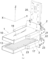
- Figure 1 shows an illustrative perspective view of a heating unit according to an exemplary embodiment of the present invention
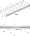
- Figure 2 shows an illustrative perspective view of heater 1 according to an exemplary embodiment of the present invention
- Figure 3 shows an illustrative exploded view of heater 1 according to an exemplary embodiment of the present invention
- Figure 4 shows a vertical cross-sectional view of heater 1 according to an exemplary embodiment of the present invention
- Figure 5 shows a vertical cross-sectional view of heater 1 according to an exemplary embodiment of the present invention
- Figure 6 shows a horizontal cross-sectional view of heater 1 according to an exemplary embodiment of the present invention, wherein the heating wire 15 is not shown
- Figure 7 shows a horizontal cross-sectional view of heater 1 according to an exemplary embodiment of the present invention, wherein the heating wire 15 is shown.
- the heater mainly comprises a housing 10, multiple heating tubes 13, and a single heating wire 15.
- the housing 10 has two opposite ends in its longitudinal direction Y.
- Multiple heating tubes 13 are arranged in the housing 10.
- the single heating wire 15 passes through multiple heating tubes 13 in sequence.
- the heating tube 13 extends along a horizontal direction X of the housing 10, and multiple heating tubes 13 are arranged in a row along the longitudinal direction Y of the housing 10.
- the arrangement density of heating tubes 13 in two end regions Z1 and Z2 near two ends of housing 10 is higher than that of the heating tubes 13 in a middle region Z3 between the two end regions Z1 and Z2 of housing 10.
- the length of the heating wire 15 set in the heating tube 13 in the end regions Z1 and Z2 is greater than the length of the heating wire 15 set in the heating tube 13 in the middle region Z3.
- the heating wire 15 can be in the shape of a spiral spring, and the pitch of the heating wire 15 in the heating tubes 13 in the end regions Z1 and Z2 is smaller than that in the heating tubes 13 in the middle region Z3, so that the length of the heating wire 15 in the heating tubes 13 in the end regions Z1 and Z2 is greater than the length of the heating wire 15 in the heating tubes 13 in the middle region Z3.
- one end of the housing 10 is used for installation on an installation bracket 20, and the two end regions Z1 and Z2 include a first end region Z1 near one end of the housing 10 and a second end region Z2 near the other end of the housing 10.
- the arrangement density of heating tubes 13 in the first end region Z1 is less than or equal to the arrangement density of the heating tubes 13 in the second end region Z2.
- the length of the heating wire 15 set in the heating tube 13 in the first end region Z1 is less than or equal to the length of the heating wire 15 set in the heating tube 13 in the second end region Z2.
- the heater 1 further comprises a pair of retaining members 14, which are arranged in the housing 10 to maintain the two ends of the row of heating tubes 13.
- the retaining member 14 is in a strip shape.
- One of the pair of retaining members 14 is configured to holding one ends of the row of heating tubes 13, the other of the pair of retaining members 14 is configured to holding the other ends of the row of heating tubes 13.
- the housing 10 has two opposite side walls in its transverse direction X, and the pair of retaining members 14 are respectively fixed to the inner sides of the two side walls of the housing 10.
- the retaining member 14 extends along the longitudinal direction Y of the housing 10, a row of positioning grooves 14a corresponding to the row of heating tubes 13 are formed on the retaining member 14.
- the two ends of heating tubes 13 are respectively held in the pair of positioning grooves 14a of the pair of retaining members 14.
- the heater 1 further includes a heat insulation pad 16, which is provided between the housing 10 and the heating tubes 13 to prevent heat from being transferred from the heating tubes 13 to the housing 10.
- the heat insulation pad 16 comprises: a first heat insulation pad 16a and a second heat insulation pad 16b.
- the first heat insulation pad 16a is set between the bottom wall of the housing 10 and the row of heating tubes 13.
- the second heat insulation pad 16b is set between the end wall of the housing 10 and the heating tube 13 at the end of the housing 10.
- a window 120 is formed on the top wall of the housing 10, and the heat of the heating tubes 13 radiates outward through the window 120 to heat an object to be heated.
- a plurality of positioning tongues 12a are formed on the edge of the window 120 of the housing 10, and the positioning tongues 12a are pressed against the top surface of the retaining member 14 to limit the position of the retaining member 14 in the height direction Z.
- the housing 10 comprises a lower housing 11 and an upper housing 12 assembled together.
- the window 120 and the positioning tongues 12a are formed on the top wall of the upper housing 12.
- the heater 1 further includes a temperature sensor 19, which is installed on the bottom wall of the housing 10 and extends into the housing 10 to detect the temperature of the heating tube 13.
- the temperature sensor 19 can be a thermocouple.
- the heater 1 further comprises a pair of mounting members 17, which are respectively fixed to both sides of one end of housing 10, for installing the heater 1 onto the installation bracket 2.
- a socket 171 is formed in the mounting member 17 for matching with a plug 23 on the installation bracket 2, allowing the heater 1 to be quickly installed on the installation bracket 2 in a plug-in manner.
- a heating unit is also disclosed.
- the heating unit mainly includes: an installation bracket 2 and a pair of heaters 1.
- the pair of heaters 1 are installed on installation bracket 2.
- the pair of heaters 1 are spaced from each other and parallel to each other in the height direction Z perpendicular to the transverse direction X and the longitudinal direction Y of the heater 1.
- At least one of the pair of heaters 1 is movably installed on the installation bracket 2, so that the spacing between the pair of heaters 1 can be adjusted to fit the size of the object (not shown) to be heated.
- the installation bracket 2 mainly includes: a mounting plate 20, a guide rail 21, a slider 22, and a plug 23.
- the installation plate 20 extends along the transverse direction X and the height direction Z of the housing 10.
- the guide rail 21 extends in a straight line along the height direction Z and is fixed to the mounting plate 20.
- the slider 22 is slidably installed on the guide rail 21.
- the plug 23 extends along the longitudinal direction Y of the housing 10 and is fixed to the slider 22. The plug 23 is inserted into the socket 171 of mounting member 17 of the heater 1, so that the heater 1 can be moved along guide rail 21 with the slider 22.
- the heating unit further comprises a heat reflection plate 3.
- the heat reflection plate 3 is set on an opening at one ends of the pair of heaters 1 and fixed to the installation bracket 2.
- the heat reflection plate 3 is used to reflect heat into the heating region between the pair of heaters 1, in order to prevent heat from flowing from the opening at one ends of the pair of heaters 1 to the outside of the heating region.
- the installation of the heating wire and heating tube can be achieved by sequentially passing a single heating wire through multiple heating tubes and positioning the two ends of the multiple heating tubes on the pair of retaining members, which is very convenient.
Landscapes
- Resistance Heating (AREA)
Abstract
Description
- This application claims the benefit of Chinese Patent Application No.
CN202320423811.7 filed on March 7, 2023 - The present invention relates to a heater and a heating unit comprising the heater, in particular to a heater and a heating unit for heating a heat shrink tube on a cable.
- In the prior art, the heating unit of a heat shrink machine typically includes two plate shaped heaters, upper and lower. In the prior art, the heating region with uniform temperature in the heating unit is limited to the middle region of the heating unit, resulting in its two ends being unable to be used for heating the heat shrink tube, which not only reduces production efficiency but also wastes some energy consumption. In addition, in the prior art, due to structural limitations, the density of the heating wire at both ends of the heater cannot be increased. This results in the temperature at both ends of the heating unit always being lower than the middle temperature, which in turn prevents its two ends from being used for heating the heat shrink tube, affecting the improvement of production efficiency.
- In the prior art, the normal operating temperature of the heater of the heat shrink machine is between 500-600°C, and the temperature difference with the external environment is too large. Therefore, during heating, heat will be lost through the openings at both ends of the upper and lower heaters, resulting in lower temperatures at the edges of the two ends of the heater, which further leads to uneven heating.
- In current technology, the heater structure is relatively simple, making it difficult to achieve differentiated arrangement of heating wires, and the processing cost is high. For example, in the prior art, only a piece of quartz glass is used to cover the heating wire; The heating wire is in sheet shape and requires precision machining to ensure consistent width. Once the heating wire is processed and formed, it is difficult to adjust it as needed. It is difficult to ensure the uniformity of the heating wire during installation.
- The present invention has been made to overcome or alleviate at least one aspect of the above mentioned disadvantages.
- According to an aspect of the present invention, there is provided a heater. The heater comprises of a housing having two opposite ends in its longitudinal direction; multiple heating tubes provided in the housing and arranged in a row along the longitudinal direction of the housing; a pair of retaining members installed in the housing; and a single heating wire passing through the multiple heating tubes in sequence. The retaining member is in a strip shape, one of the pair of retaining members is configured to holding one ends of the row of heating tubes, the other of the pair of retaining members is configured to holding the other ends of the row of heating tubes.
- According to an exemplary embodiment of the present invention, the housing has two opposite side walls in its transverse direction, and the pair of retaining members are respectively fixed to the inner sides of the two side walls of the housing; the retaining member extends in the longitudinal direction of the housing, a row of positioning grooves corresponding to the row of heating tubes are formed on the retaining member, and the two ends of the heating tubes are respectively held in the positioning grooves of the pair of retaining members.
- According to another exemplary embodiment of the present invention, a window is formed on the top wall of the housing, and the heat of the heating tube radiates outward through the window to heat an object to be heated.
- According to another exemplary embodiment of the present invention, a positioning tongue is formed on the edge of the window of the housing, and the positioning tongue is pressed against the top surface of the retaining member to limit the position of the retaining member in a height direction of the housing.
- According to another exemplary embodiment of the present invention, the housing comprises a lower housing and an upper housing assembled together, and the window and the positioning tongue are formed on the top wall of the upper housing.
- According to another exemplary embodiment of the present invention, the heater further comprises a pair of mounting members which are respectively fixed to both sides of one end of the housing, for installing the heater onto an installation bracket.
- According to another exemplary embodiment of the present invention, a socket is formed on the mounting member for matching with a plug on the installation bracket, allowing the heater to be quickly installed on the installation bracket in a plug-in manner.
- According to another exemplary embodiment of the present invention, the heater further comprises a heat insulation pad which is provided between the housing and the heating tube to prevent heat from being transferred from the heating tube to the housing.
- According to another exemplary embodiment of the present invention, the heat insulation pad comprises of a first heat insulation pad which is provided between the bottom wall of the housing and the row of heating tubes; and a second heat insulation pad which is provided between the end wall of the housing and the heating tube at the end of the housing.
- According to another exemplary embodiment of the present invention, the heater further comprises a temperature sensor which is installed on the bottom wall of the housing and extends into the housing to detect the temperature of the heating tube.
- According to another exemplary embodiment of the present invention, an arrangement density of the heating tubes in two end regions near the two ends of the housing is greater than an arrangement density of the heating tubes in a middle region between the two end regions of the housing.
- According to another aspect of the present invention, there is provided a heating unit. The heating unit comprises of an installation bracket; and a pair of heaters which are installed on the installation bracket. The pair of heaters are spaced from each other and parallel to each other in a height direction perpendicular to a transverse direction and a longitudinal direction of the heater.
- According to an exemplary embodiment of the present invention, at least one of the pairs of heaters is movably mounted on the installation bracket, so that the spacing between the pairs of heaters can be adjusted to fit the size of an object to be heated.
- According to another exemplary embodiment of the present invention, the installation bracket comprises of a mounting plate that extends along the transverse direction and a height direction of the housing; a guide rail which extends in a straight line along the height direction and is fixed to the mounting plate; a slider which is slidably installed on the guide rail; and a plug which extends along the longitudinal direction of the housing and is fixed to the slider. The plug is inserted into the socket of the mounting member of the heater, so that the heater is capable of being moved with the slider along the guide rail.
- According to another exemplary embodiment of the present invention, the heating unit further comprises a heat reflection plate which is provided on an opening at one ends of the pair of heaters and fixed to the installation bracket, the heat reflection plate is used to reflect heat into a heating region between the pair of heaters, to prevent heat from flowing from the opening at one ends of the pair of heaters to the outside of the heating region.
- In the aforementioned exemplary embodiments of the present invention, the structure of the heater is simple and easy to assemble. In the present invention, the installation of heating wire and heating tubes can be achieved by sequentially passing a single heating wire through multiple heating tubes and positioning the two ends of the multiple heating tubes on the pair of retaining members, which saves time and effort.
- In addition, in some exemplary embodiments according to the present invention, the arrangement density of the heating tubes in the end region of the heater is greater than that in the middle region of the heater, which makes the heating temperature in the end region of the heater basically consistent with the heating temperature in the middle region of the heater, thereby improving the heating uniformity of the heater.
- The above and other features of the present invention will become more apparent by describing in detail exemplary embodiments thereof with reference to the accompanying drawings, in which:
-
Figure 1 shows an illustrative perspective view of a heating unit according to an exemplary embodiment of the present invention; -
Figure 2 shows an illustrative perspective view of a heater according to an exemplary embodiment of the present invention; -
Figure 3 shows an illustrative exploded view of a heater according to an exemplary embodiment of the present invention; -
Figure 4 shows a vertical cross-sectional view of a heater according to an exemplary embodiment of the present invention; -
Figure 5 shows a vertical cross-sectional view of a heater according to an exemplary embodiment of the present invention; -
Figure 6 shows a horizontal cross-sectional view of a heater according to an exemplary embodiment of the present invention, wherein the heating wire is not shown; and -
Figure 7 shows a horizontal cross-sectional view of a heater according to an exemplary embodiment of the present invention, wherein the heating wire is shown. - Exemplary embodiments of the present disclosure will be described hereinafter in detail with reference to the attached drawings, wherein the like reference numerals refer to the like elements. The present disclosure may, however, be embodied in many different forms and should not be construed as being limited to the embodiment set forth herein; rather, these embodiments are provided so that the present disclosure will be thorough and complete, and will fully convey the concept of the disclosure to those skilled in the art.
- In the following detailed description, for purposes of explanation, numerous specific details are set forth in order to provide a thorough understanding of the disclosed embodiments. It will be apparent, however, that one or more embodiments may be practiced without these specific details. In other instances, well-known structures and devices are schematically shown in order to simplify the drawing.
- According to a general concept of the present invention, there is provided a heater. The heater comprises of a housing having two opposite ends in its longitudinal direction; multiple heating tubes provided in the housing and arranged in a row along the longitudinal direction of the housing; a pair of retaining members installed in the housing; and a single heating wire passing through the multiple heating tubes in sequence. The retaining member is in a strip shape, one of the pair of retaining members is configured to holding one ends of the row of heating tubes, the other of the pair of retaining members is configured to holding the other ends of the row of heating tubes.
- According to another general concept of the present invention, there is provided a heater. The heater comprises of: a housing having two opposite ends in its longitudinal direction; multiple heating tubes provided in the housing; and a single heating wire passing through the multiple heating tubes in sequence. The heating tubes extend along a horizontal direction of the housing, and multiple heating tubes are arranged in a row along the longitudinal direction of the housing. An arrangement density of the heating tubes in two end regions near the two ends of the housing is greater than an arrangement density of the heating tubes in a middle region between the two end regions of the housing.
- According to another general concept of the present invention, there is provided a heating unit. The heating unit comprises of: an installation bracket; and a pair of heaters which are installed on the installation bracket. The pair of heaters are spaced from each other and parallel to each other in a height direction perpendicular to a transverse direction and a longitudinal direction of the heater.
-
Figure 1 shows an illustrative perspective view of a heating unit according to an exemplary embodiment of the present invention;Figure 2 shows an illustrative perspective view ofheater 1 according to an exemplary embodiment of the present invention;Figure 3 shows an illustrative exploded view ofheater 1 according to an exemplary embodiment of the present invention;Figure 4 shows a vertical cross-sectional view ofheater 1 according to an exemplary embodiment of the present invention;Figure 5 shows a vertical cross-sectional view ofheater 1 according to an exemplary embodiment of the present invention;Figure 6 shows a horizontal cross-sectional view ofheater 1 according to an exemplary embodiment of the present invention, wherein theheating wire 15 is not shown;Figure 7 shows a horizontal cross-sectional view ofheater 1 according to an exemplary embodiment of the present invention, wherein theheating wire 15 is shown. - As shown in
Figures 1 to 7 , in the illustrated embodiments, the heater mainly comprises ahousing 10,multiple heating tubes 13, and asingle heating wire 15. Thehousing 10 has two opposite ends in its longitudinal direction Y.Multiple heating tubes 13 are arranged in thehousing 10. Thesingle heating wire 15 passes throughmultiple heating tubes 13 in sequence. Theheating tube 13 extends along a horizontal direction X of thehousing 10, andmultiple heating tubes 13 are arranged in a row along the longitudinal direction Y of thehousing 10. The arrangement density ofheating tubes 13 in two end regions Z1 and Z2 near two ends ofhousing 10 is higher than that of theheating tubes 13 in a middle region Z3 between the two end regions Z1 and Z2 ofhousing 10. - As shown in
Figures 1 to 7 , in the illustrated embodiments, the length of theheating wire 15 set in theheating tube 13 in the end regions Z1 and Z2 is greater than the length of theheating wire 15 set in theheating tube 13 in the middle region Z3. In the illustrated embodiment, theheating wire 15 can be in the shape of a spiral spring, and the pitch of theheating wire 15 in theheating tubes 13 in the end regions Z1 and Z2 is smaller than that in theheating tubes 13 in the middle region Z3, so that the length of theheating wire 15 in theheating tubes 13 in the end regions Z1 and Z2 is greater than the length of theheating wire 15 in theheating tubes 13 in the middle region Z3. - As shown in
Figures 1 to 7 , in the illustrated embodiments, one end of thehousing 10 is used for installation on aninstallation bracket 20, and the two end regions Z1 and Z2 include a first end region Z1 near one end of thehousing 10 and a second end region Z2 near the other end of thehousing 10. The arrangement density ofheating tubes 13 in the first end region Z1 is less than or equal to the arrangement density of theheating tubes 13 in the second end region Z2. - As shown in
Figures 1 to 7 , in the illustrated embodiments, the length of theheating wire 15 set in theheating tube 13 in the first end region Z1 is less than or equal to the length of theheating wire 15 set in theheating tube 13 in the second end region Z2. - As shown in
Figures 1 to 7 , in the illustrated embodiments, theheater 1 further comprises a pair of retainingmembers 14, which are arranged in thehousing 10 to maintain the two ends of the row ofheating tubes 13. The retainingmember 14 is in a strip shape. One of the pair of retainingmembers 14 is configured to holding one ends of the row ofheating tubes 13, the other of the pair of retainingmembers 14 is configured to holding the other ends of the row ofheating tubes 13. - As shown in
Figures 1 to 7 , in the illustrated embodiments, thehousing 10 has two opposite side walls in its transverse direction X, and the pair of retainingmembers 14 are respectively fixed to the inner sides of the two side walls of thehousing 10. The retainingmember 14 extends along the longitudinal direction Y of thehousing 10, a row ofpositioning grooves 14a corresponding to the row ofheating tubes 13 are formed on the retainingmember 14. The two ends ofheating tubes 13 are respectively held in the pair ofpositioning grooves 14a of the pair of retainingmembers 14. - As shown in
Figures 1 to 7 , in the illustrated embodiments, theheater 1 further includes aheat insulation pad 16, which is provided between thehousing 10 and theheating tubes 13 to prevent heat from being transferred from theheating tubes 13 to thehousing 10. - As shown in
Figures 1 to 7 , in the illustrated embodiments, theheat insulation pad 16 comprises: a firstheat insulation pad 16a and a secondheat insulation pad 16b. The firstheat insulation pad 16a is set between the bottom wall of thehousing 10 and the row ofheating tubes 13. The secondheat insulation pad 16b is set between the end wall of thehousing 10 and theheating tube 13 at the end of thehousing 10. - As shown in
Figures 1 to 7 , in the illustrated embodiments, awindow 120 is formed on the top wall of thehousing 10, and the heat of theheating tubes 13 radiates outward through thewindow 120 to heat an object to be heated. - As shown in
Figures 1 to 7 , in the illustrated embodiments, a plurality ofpositioning tongues 12a are formed on the edge of thewindow 120 of thehousing 10, and thepositioning tongues 12a are pressed against the top surface of the retainingmember 14 to limit the position of the retainingmember 14 in the height direction Z. - As shown in
Figures 1 to 7 , in the illustrated embodiments, thehousing 10 comprises alower housing 11 and anupper housing 12 assembled together. Thewindow 120 and thepositioning tongues 12a are formed on the top wall of theupper housing 12. - As shown in
Figures 1 to 7 , in the illustrated embodiments, theheater 1 further includes atemperature sensor 19, which is installed on the bottom wall of thehousing 10 and extends into thehousing 10 to detect the temperature of theheating tube 13. In an embodiment, thetemperature sensor 19 can be a thermocouple. - As shown in
Figures 1 to 7 , in the illustrated embodiments, theheater 1 further comprises a pair of mountingmembers 17, which are respectively fixed to both sides of one end ofhousing 10, for installing theheater 1 onto theinstallation bracket 2. - As shown in
Figures 1 to 7 , in the illustrated embodiments, asocket 171 is formed in the mountingmember 17 for matching with aplug 23 on theinstallation bracket 2, allowing theheater 1 to be quickly installed on theinstallation bracket 2 in a plug-in manner. - As shown in
Figures 1 to 7 , in another exemplary embodiment of the present invention, a heating unit is also disclosed. The heating unit mainly includes: aninstallation bracket 2 and a pair ofheaters 1. The pair ofheaters 1 are installed oninstallation bracket 2. The pair ofheaters 1 are spaced from each other and parallel to each other in the height direction Z perpendicular to the transverse direction X and the longitudinal direction Y of theheater 1. - As shown in
Figures 1 to 7 , in the illustrated embodiments, at least one of the pair ofheaters 1 is movably installed on theinstallation bracket 2, so that the spacing between the pair ofheaters 1 can be adjusted to fit the size of the object (not shown) to be heated. - As shown in
Figures 1 to 7 , in the illustrated embodiments, theinstallation bracket 2 mainly includes: a mountingplate 20, aguide rail 21, aslider 22, and aplug 23. Theinstallation plate 20 extends along the transverse direction X and the height direction Z of thehousing 10. Theguide rail 21 extends in a straight line along the height direction Z and is fixed to the mountingplate 20. Theslider 22 is slidably installed on theguide rail 21. Theplug 23 extends along the longitudinal direction Y of thehousing 10 and is fixed to theslider 22. Theplug 23 is inserted into thesocket 171 of mountingmember 17 of theheater 1, so that theheater 1 can be moved alongguide rail 21 with theslider 22. - As shown in
Figures 1 to 7 , in the illustrated embodiments, the heating unit further comprises aheat reflection plate 3. Theheat reflection plate 3 is set on an opening at one ends of the pair ofheaters 1 and fixed to theinstallation bracket 2. Theheat reflection plate 3 is used to reflect heat into the heating region between the pair ofheaters 1, in order to prevent heat from flowing from the opening at one ends of the pair ofheaters 1 to the outside of the heating region. - In the aforementioned exemplary embodiments of the present invention, the installation of the heating wire and heating tube can be achieved by sequentially passing a single heating wire through multiple heating tubes and positioning the two ends of the multiple heating tubes on the pair of retaining members, which is very convenient.
- It should be appreciated for those skilled in this art that the above embodiments are intended to be illustrated, and not restrictive. For example, many modifications may be made to the above embodiments by those skilled in this art, and various features described in different embodiments may be freely combined with each other without conflicting in configuration or principle.
- Although several exemplary embodiments have been shown and described, it would be appreciated by those skilled in the art that various changes or modifications may be made in these embodiments without departing from the principles and spirit of the disclosure, the scope of which is defined in the claims and their equivalents.
- As used herein, an element recited in the singular and proceeded with the word "a" or "an" should be understood as not excluding plural of said elements or steps, unless such exclusion is explicitly stated. Furthermore, references to "one embodiment" of the present invention are not intended to be interpreted as excluding the existence of additional embodiments that also incorporate the recited features. Moreover, unless explicitly stated to the contrary, embodiments "comprising" or "having" an element or a plurality of elements having a particular property may include additional such elements not having that property.
Claims (15)
- A heater, comprising:a housing (10) having two opposite ends in its longitudinal direction (Y);multiple heating tubes (13) provided in the housing (10) and arranged in a row along the longitudinal direction (Y) of the housing (10);a pair of retaining members (14) installed in the housing (10); anda single heating wire (15) passing through the multiple heating tubes (13) in sequence,wherein the retaining member is in a strip shape, one of the pair of retaining members (14) is configured to holding one ends of the row of heating tubes (13), the other of the pair of retaining members (14) is configured to holding the other ends of the row of heating tubes (13).
- The heater according to claim 1,wherein the housing (10) has two opposite side walls in its transverse direction (X), and the pair of retaining members (14) are respectively fixed to the inner sides of the two side walls of the housing (10);wherein the retaining member (14) extends in the longitudinal direction (Y) of the housing (10), a row of positioning grooves (14a) corresponding to the row of heating tubes (13) are formed on the retaining member (14), and the two ends of the heating tubes (13) are respectively held in the positioning grooves (14a) of the pair of retaining members (14).
- The heater according to claim 2,
wherein a window (120) is formed on the top wall of the housing (10), and the heat of the heating tube (13) radiates outward through the window (120) to heat an object to be heated. - The heater according to claim 3,
wherein a positioning tongue (12a) is formed on the edge of the window (120) of the housing (10), and the positioning tongue (12a) is pressed against the top surface of the retaining member (14) to limit the position of the retaining member (14) in a height direction (Z) of the housing (10). - The heater according to claim 4,
wherein the housing (10) comprises a lower housing (11) and an upper housing (12) assembled together, and the window (120) and the positioning tongue (12a) are formed on the top wall of the upper housing (12). - The heater according to claim 1, further comprising:
a pair of mounting members (17) which are respectively fixed to both sides of one end of the housing (10), for installing the heater (1) onto an installation bracket (2). - The heater according to claim 6,
wherein a socket (171) is formed on the mounting member (17) for matching with a plug (23) on the installation bracket (2), allowing the heater (1) to be quickly installed on the installation bracket (2) in a plug-in manner. - The heater according to claim 1, further comprising:
a heat insulation pad (16) which is provided between the housing (10) and the heating tube (13) to prevent heat from being transferred from the heating tube (13) to the housing (10). - The heater according to claim 8,
wherein the heat insulation pad (16) comprises ofa first heat insulation pad (16a) which is provided between the bottom wall of the housing (10) and the row of heating tubes (13); anda second heat insulation pad (16b) which is provided between the end wall of the housing (10) and the heating tube (13) at the end of the housing (10). - The heater according to claim 1, further comprising:
a temperature sensor (19) which is installed on the bottom wall of the housing (10) and extends into the housing (10) to detect the temperature of the heating tube (13). - The heater according to any one of claims 1-10,
wherein an arrangement density of the heating tubes (13) in two end regions (Z1, Z2) near the two ends of the housing (10) is greater than an arrangement density of the heating tubes (13) in a middle region (Z3) between the two end regions (Z1, Z2) of the housing (10). - A heating unit, comprising:an installation bracket (2); anda pair of heaters (1) which are installed on the installation bracket (2),wherein the heater (1) is claimed in any one of claims 1-11, and the pair of heaters (1) are spaced from each other and parallel to each other in a height direction (Z) perpendicular to a transverse direction (X) and a longitudinal direction (Y) of the heater (1).
- The heating unit according to claim 12,
wherein at least one of the pairs of heaters (1) is movably mounted on the installation bracket (2), so that the spacing between the pairs of heaters (1) can be adjusted to fit the size of an object to be heated. - The heating unit according to claim 12,wherein the installation bracket (2) comprises of:a mounting plate (20) that extends along the transverse direction (X) and a height direction (Z) of the housing (10);a guide rail (21) which extends in a straight line along the height direction (Z) and is fixed to the mounting plate (20);a slider (22) which is slidably installed on the guide rail (21); anda plug (23) which extends along the longitudinal direction (Y) of the housing (10) and is fixed to the slider (22),wherein the plug (23) is inserted into the socket (171) of the mounting member (17) of the heater (1), so that the heater (1) is capable of being moved with the slider (22) along the guide rail (21).
- The heating unit according to claim 12, further comprising:a heat reflection plate (3) which is provided on an opening at one ends of the pair of heaters (1) and fixed to the installation bracket (2),wherein the heat reflection plate (3) is used to reflect heat into a heating region between the pair of heaters (1), to prevent heat from flowing from the opening at one ends of the pair of heaters (1) to the outside of the heating region.
Applications Claiming Priority (1)
| Application Number | Priority Date | Filing Date | Title |
|---|---|---|---|
| CN202320423811.7U CN219248089U (en) | 2023-03-07 | 2023-03-07 | Heater and heating unit |
Publications (2)
| Publication Number | Publication Date |
|---|---|
| EP4429403A1 true EP4429403A1 (en) | 2024-09-11 |
| EP4429403B1 EP4429403B1 (en) | 2025-11-12 |
Family
ID=86804301
Family Applications (1)
| Application Number | Title | Priority Date | Filing Date |
|---|---|---|---|
| EP24161119.3A Active EP4429403B1 (en) | 2023-03-07 | 2024-03-04 | Heater and heating unit |
Country Status (6)
| Country | Link |
|---|---|
| US (1) | US20240306267A1 (en) |
| EP (1) | EP4429403B1 (en) |
| JP (1) | JP2024127818A (en) |
| CN (1) | CN219248089U (en) |
| AR (1) | AR132057A1 (en) |
| MX (1) | MX2024002784A (en) |
Citations (3)
| Publication number | Priority date | Publication date | Assignee | Title |
|---|---|---|---|---|
| CN215619954U (en) * | 2021-09-27 | 2022-01-25 | 苏州工业园区六旭自动化设备有限公司 | Thermal shrinkage machine with automatically move telescopic cavity |
| CN217597861U (en) * | 2022-05-25 | 2022-10-18 | 泰科电子(上海)有限公司 | Motion mechanism, heating device and thermal shrinkage machine |
| CN115551133A (en) * | 2021-06-30 | 2022-12-30 | 江苏天宏机械工业有限公司 | Heating pipe movable mechanism |
-
2023
- 2023-03-07 CN CN202320423811.7U patent/CN219248089U/en active Active
-
2024
- 2024-03-04 MX MX2024002784A patent/MX2024002784A/en unknown
- 2024-03-04 JP JP2024031813A patent/JP2024127818A/en active Pending
- 2024-03-04 EP EP24161119.3A patent/EP4429403B1/en active Active
- 2024-03-05 AR ARP240100547A patent/AR132057A1/en unknown
- 2024-03-06 US US18/596,832 patent/US20240306267A1/en active Pending
Patent Citations (3)
| Publication number | Priority date | Publication date | Assignee | Title |
|---|---|---|---|---|
| CN115551133A (en) * | 2021-06-30 | 2022-12-30 | 江苏天宏机械工业有限公司 | Heating pipe movable mechanism |
| CN215619954U (en) * | 2021-09-27 | 2022-01-25 | 苏州工业园区六旭自动化设备有限公司 | Thermal shrinkage machine with automatically move telescopic cavity |
| CN217597861U (en) * | 2022-05-25 | 2022-10-18 | 泰科电子(上海)有限公司 | Motion mechanism, heating device and thermal shrinkage machine |
Also Published As
| Publication number | Publication date |
|---|---|
| US20240306267A1 (en) | 2024-09-12 |
| JP2024127818A (en) | 2024-09-20 |
| AR132057A1 (en) | 2025-05-21 |
| MX2024002784A (en) | 2024-09-09 |
| CN219248089U (en) | 2023-06-23 |
| EP4429403B1 (en) | 2025-11-12 |
Similar Documents
| Publication | Publication Date | Title |
|---|---|---|
| EP2682669B1 (en) | Linear light irradiation device and method for producing same | |
| US4195687A (en) | Space heating panels | |
| FI66083B (en) | FOTLISTVAERMEAPPARAT | |
| EP0355210A1 (en) | Heating element | |
| EP4429403A1 (en) | Heater and heating unit | |
| JP6917778B2 (en) | Terminal bending tool | |
| US20130319996A1 (en) | Household appliance having supports supporting a glass heating element of a warming drawer | |
| CN104868423A (en) | Current carrying systems and methods of assembling the same | |
| CN201425342Y (en) | Electric oil heater | |
| JP2013020854A (en) | Base plate for electrothermal heater | |
| BR102024004283A2 (en) | HEATER AND HEATING UNIT | |
| JP6450927B2 (en) | Ventilation duct | |
| EP2600076B1 (en) | Dry heat modular electric radiator | |
| JP4686205B2 (en) | Connection structure of sheet metal member and other members | |
| CN222628621U (en) | A U-shaped casing drying machine | |
| CN218791881U (en) | Temperature sensor mounting structure of air fryer | |
| CN217335939U (en) | Heating assembly | |
| KR101627252B1 (en) | An Heating Apparatus Having a Strip Heater | |
| CN102573140B (en) | Fixing structure for lug plate | |
| ITBZ960041A1 (en) | THERMAL SKIRTING BOARDS FOR THE INSTALLATION OF HEATING, AIR CONDITIONING, ELECTRICAL LINES AND/OR ANTENNAS. | |
| CN216930337U (en) | Heating core | |
| CN219351923U (en) | Heating frame structure | |
| CN223553485U (en) | Heating tube and heating device | |
| KR102173933B1 (en) | Hairpin-shaped heat exchange tube guide device | |
| JPH0326638Y2 (en) |
Legal Events
| Date | Code | Title | Description |
|---|---|---|---|
| PUAI | Public reference made under article 153(3) epc to a published international application that has entered the european phase |
Free format text: ORIGINAL CODE: 0009012 |
|
| STAA | Information on the status of an ep patent application or granted ep patent |
Free format text: STATUS: THE APPLICATION HAS BEEN PUBLISHED |
|
| AK | Designated contracting states |
Kind code of ref document: A1 Designated state(s): AL AT BE BG CH CY CZ DE DK EE ES FI FR GB GR HR HU IE IS IT LI LT LU LV MC ME MK MT NL NO PL PT RO RS SE SI SK SM TR |
|
| STAA | Information on the status of an ep patent application or granted ep patent |
Free format text: STATUS: REQUEST FOR EXAMINATION WAS MADE |
|
| 17P | Request for examination filed |
Effective date: 20250303 |
|
| GRAP | Despatch of communication of intention to grant a patent |
Free format text: ORIGINAL CODE: EPIDOSNIGR1 |
|
| STAA | Information on the status of an ep patent application or granted ep patent |
Free format text: STATUS: GRANT OF PATENT IS INTENDED |
|
| INTG | Intention to grant announced |
Effective date: 20250711 |
|
| P01 | Opt-out of the competence of the unified patent court (upc) registered |
Free format text: CASE NUMBER: UPC_APP_3066_4429403/2025 Effective date: 20250811 |
|
| GRAS | Grant fee paid |
Free format text: ORIGINAL CODE: EPIDOSNIGR3 |
|
| GRAA | (expected) grant |
Free format text: ORIGINAL CODE: 0009210 |
|
| STAA | Information on the status of an ep patent application or granted ep patent |
Free format text: STATUS: THE PATENT HAS BEEN GRANTED |
|
| AK | Designated contracting states |
Kind code of ref document: B1 Designated state(s): AL AT BE BG CH CY CZ DE DK EE ES FI FR GB GR HR HU IE IS IT LI LT LU LV MC ME MK MT NL NO PL PT RO RS SE SI SK SM TR |
|
| REG | Reference to a national code |
Ref country code: CH Ref legal event code: F10 Free format text: ST27 STATUS EVENT CODE: U-0-0-F10-F00 (AS PROVIDED BY THE NATIONAL OFFICE) Effective date: 20251112 Ref country code: GB Ref legal event code: FG4D |
|
| REG | Reference to a national code |
Ref country code: DE Ref legal event code: R096 Ref document number: 602024001216 Country of ref document: DE |
|
| REG | Reference to a national code |
Ref country code: IE Ref legal event code: FG4D |
|
| REG | Reference to a national code |
Ref country code: NL Ref legal event code: MP Effective date: 20251112 |
|
| PG25 | Lapsed in a contracting state [announced via postgrant information from national office to epo] |
Ref country code: ES Free format text: LAPSE BECAUSE OF FAILURE TO SUBMIT A TRANSLATION OF THE DESCRIPTION OR TO PAY THE FEE WITHIN THE PRESCRIBED TIME-LIMIT Effective date: 20251112 |
|
| REG | Reference to a national code |
Ref country code: LT Ref legal event code: MG9D |
|
| PG25 | Lapsed in a contracting state [announced via postgrant information from national office to epo] |
Ref country code: NO Free format text: LAPSE BECAUSE OF FAILURE TO SUBMIT A TRANSLATION OF THE DESCRIPTION OR TO PAY THE FEE WITHIN THE PRESCRIBED TIME-LIMIT Effective date: 20260212 |
|
| PG25 | Lapsed in a contracting state [announced via postgrant information from national office to epo] |
Ref country code: FI Free format text: LAPSE BECAUSE OF FAILURE TO SUBMIT A TRANSLATION OF THE DESCRIPTION OR TO PAY THE FEE WITHIN THE PRESCRIBED TIME-LIMIT Effective date: 20251112 Ref country code: AT Free format text: LAPSE BECAUSE OF FAILURE TO SUBMIT A TRANSLATION OF THE DESCRIPTION OR TO PAY THE FEE WITHIN THE PRESCRIBED TIME-LIMIT Effective date: 20251112 Ref country code: HR Free format text: LAPSE BECAUSE OF FAILURE TO SUBMIT A TRANSLATION OF THE DESCRIPTION OR TO PAY THE FEE WITHIN THE PRESCRIBED TIME-LIMIT Effective date: 20251112 |
|
| PGFP | Annual fee paid to national office [announced via postgrant information from national office to epo] |
Ref country code: AT Payment date: 20260301 Year of fee payment: 3 |
|
| REG | Reference to a national code |
Ref country code: AT Ref legal event code: MK05 Ref document number: 1857930 Country of ref document: AT Kind code of ref document: T Effective date: 20251112 |
|
| PG25 | Lapsed in a contracting state [announced via postgrant information from national office to epo] |
Ref country code: NL Free format text: LAPSE BECAUSE OF FAILURE TO SUBMIT A TRANSLATION OF THE DESCRIPTION OR TO PAY THE FEE WITHIN THE PRESCRIBED TIME-LIMIT Effective date: 20251112 |
|
| PG25 | Lapsed in a contracting state [announced via postgrant information from national office to epo] |
Ref country code: RS Free format text: LAPSE BECAUSE OF FAILURE TO SUBMIT A TRANSLATION OF THE DESCRIPTION OR TO PAY THE FEE WITHIN THE PRESCRIBED TIME-LIMIT Effective date: 20260212 |
|
| PG25 | Lapsed in a contracting state [announced via postgrant information from national office to epo] |
Ref country code: IS Free format text: LAPSE BECAUSE OF FAILURE TO SUBMIT A TRANSLATION OF THE DESCRIPTION OR TO PAY THE FEE WITHIN THE PRESCRIBED TIME-LIMIT Effective date: 20260312 |
|
| PG25 | Lapsed in a contracting state [announced via postgrant information from national office to epo] |
Ref country code: PT Free format text: LAPSE BECAUSE OF FAILURE TO SUBMIT A TRANSLATION OF THE DESCRIPTION OR TO PAY THE FEE WITHIN THE PRESCRIBED TIME-LIMIT Effective date: 20260312 |
|
| PG25 | Lapsed in a contracting state [announced via postgrant information from national office to epo] |
Ref country code: PL Free format text: LAPSE BECAUSE OF FAILURE TO SUBMIT A TRANSLATION OF THE DESCRIPTION OR TO PAY THE FEE WITHIN THE PRESCRIBED TIME-LIMIT Effective date: 20251112 |
|
| PG25 | Lapsed in a contracting state [announced via postgrant information from national office to epo] |
Ref country code: LV Free format text: LAPSE BECAUSE OF FAILURE TO SUBMIT A TRANSLATION OF THE DESCRIPTION OR TO PAY THE FEE WITHIN THE PRESCRIBED TIME-LIMIT Effective date: 20251112 |