EP4429297A1 - Attacker detection in ambient iot - Google Patents
Attacker detection in ambient iot Download PDFInfo
- Publication number
- EP4429297A1 EP4429297A1 EP24161130.0A EP24161130A EP4429297A1 EP 4429297 A1 EP4429297 A1 EP 4429297A1 EP 24161130 A EP24161130 A EP 24161130A EP 4429297 A1 EP4429297 A1 EP 4429297A1
- Authority
- EP
- European Patent Office
- Prior art keywords
- signal
- attackers
- power profile
- tag
- example embodiments
- Prior art date
- Legal status (The legal status is an assumption and is not a legal conclusion. Google has not performed a legal analysis and makes no representation as to the accuracy of the status listed.)
- Granted
Links
Images



Classifications
-
- H—ELECTRICITY
- H04—ELECTRIC COMMUNICATION TECHNIQUE
- H04W—WIRELESS COMMUNICATION NETWORKS
- H04W12/00—Security arrangements; Authentication; Protecting privacy or anonymity
- H04W12/12—Detection or prevention of fraud
- H04W12/121—Wireless intrusion detection systems [WIDS]; Wireless intrusion prevention systems [WIPS]
-
- H—ELECTRICITY
- H04—ELECTRIC COMMUNICATION TECHNIQUE
- H04L—TRANSMISSION OF DIGITAL INFORMATION, e.g. TELEGRAPHIC COMMUNICATION
- H04L63/00—Network architectures or network communication protocols for network security
- H04L63/14—Network architectures or network communication protocols for network security for detecting or protecting against malicious traffic
- H04L63/1408—Network architectures or network communication protocols for network security for detecting or protecting against malicious traffic by monitoring network traffic
- H04L63/1416—Event detection, e.g. attack signature detection
-
- G—PHYSICS
- G16—INFORMATION AND COMMUNICATION TECHNOLOGY [ICT] SPECIALLY ADAPTED FOR SPECIFIC APPLICATION FIELDS
- G16Y—INFORMATION AND COMMUNICATION TECHNOLOGY SPECIALLY ADAPTED FOR THE INTERNET OF THINGS [IoT]
- G16Y30/00—IoT infrastructure
- G16Y30/10—Security thereof
-
- H—ELECTRICITY
- H04—ELECTRIC COMMUNICATION TECHNIQUE
- H04K—SECRET COMMUNICATION; JAMMING OF COMMUNICATION
- H04K3/00—Jamming of communication; Counter-measures
- H04K3/20—Countermeasures against jamming
- H04K3/22—Countermeasures against jamming including jamming detection and monitoring
-
- H—ELECTRICITY
- H04—ELECTRIC COMMUNICATION TECHNIQUE
- H04K—SECRET COMMUNICATION; JAMMING OF COMMUNICATION
- H04K3/00—Jamming of communication; Counter-measures
- H04K3/40—Jamming having variable characteristics
- H04K3/45—Jamming having variable characteristics characterized by including monitoring of the target or target signal, e.g. in reactive jammers or follower jammers for example by means of an alternation of jamming phases and monitoring phases, called "look-through mode"
-
- H—ELECTRICITY
- H04—ELECTRIC COMMUNICATION TECHNIQUE
- H04K—SECRET COMMUNICATION; JAMMING OF COMMUNICATION
- H04K3/00—Jamming of communication; Counter-measures
- H04K3/60—Jamming involving special techniques
- H04K3/65—Jamming involving special techniques using deceptive jamming or spoofing, e.g. transmission of false signals for premature triggering of RCIED, for forced connection or disconnection to/from a network or for generation of dummy target signal
-
- H—ELECTRICITY
- H04—ELECTRIC COMMUNICATION TECHNIQUE
- H04K—SECRET COMMUNICATION; JAMMING OF COMMUNICATION
- H04K3/00—Jamming of communication; Counter-measures
- H04K3/80—Jamming or countermeasure characterized by its function
- H04K3/86—Jamming or countermeasure characterized by its function related to preventing deceptive jamming or unauthorized interrogation or access, e.g. WLAN access or RFID reading
-
- H—ELECTRICITY
- H04—ELECTRIC COMMUNICATION TECHNIQUE
- H04W—WIRELESS COMMUNICATION NETWORKS
- H04W4/00—Services specially adapted for wireless communication networks; Facilities therefor
- H04W4/80—Services using short range communication, e.g. near-field communication [NFC], radio-frequency identification [RFID] or low energy communication
-
- H—ELECTRICITY
- H04—ELECTRIC COMMUNICATION TECHNIQUE
- H04K—SECRET COMMUNICATION; JAMMING OF COMMUNICATION
- H04K2203/00—Jamming of communication; Countermeasures
- H04K2203/10—Jamming or countermeasure used for a particular application
- H04K2203/20—Jamming or countermeasure used for a particular application for contactless carriers, e.g. RFID carriers
-
- H—ELECTRICITY
- H04—ELECTRIC COMMUNICATION TECHNIQUE
- H04W—WIRELESS COMMUNICATION NETWORKS
- H04W12/00—Security arrangements; Authentication; Protecting privacy or anonymity
- H04W12/12—Detection or prevention of fraud
- H04W12/121—Wireless intrusion detection systems [WIDS]; Wireless intrusion prevention systems [WIPS]
- H04W12/122—Counter-measures against attacks; Protection against rogue devices
Definitions
- Various example embodiments of the present disclosure generally relate to the field of telecommunication and in particular, to methods, devices, apparatuses and computer readable storage media for attacker detection in ambient Internet of Things (IoT).
- IoT ambient Internet of Things
- IoT technology has evolved to be suitable for cellular deployment. Such IoT technology may rely on ultra-low complexity devices with ultra-low power consumption for the very-low end IoT applications.
- energy storage two types of IoT devices are considered, that is, pure batteryless devices and devices with energy storage capability.
- the batteryless devices are with no energy storage capability, and completely dependent on the availability of the ambient source of energy it is harvesting.
- the devices with energy storage capability are supplied by ambient sources via energy harvesting, and thus may not need to be replaced or recharged manually and can manage a short period of ambient energy unavailability.
- IoT devices are to be detected via a tag detection session.
- the fraudulent devices may disturb the tag detection session by proactively or reactively emitting malicious or jamming signals, so that the NR network is prevented from acquiring tag information, and ultimately compromising the detection integrity.
- an apparatus comprising at least one processor; and at least one memory storing instructions that, when executed by the at least one processor, cause the apparatus at least to perform: receive at least one signal which is at least associated with a trick tag signal transmitted from a terminal device; determine a number of attackers of a tag detection session based on the at least one signal; and transmit, to a network device, attacker information at least comprising the number of attackers.
- an apparatus comprising at least one processor; and at least one memory storing instructions that, when executed by the at least one processor, cause the apparatus at least to perform: receive, from a device, attacker information at least comprising a number of attackers of a tag detection session, wherein the number of attackers is determined based on at least one signal received at the device, and the at least one signal is at least associated with a trick tag signal transmitted from a terminal device.
- a method comprises: receiving at least one signal which is at least associated with a trick tag signal transmitted from a terminal device; determining a number of attackers of a tag detection session based on the at least one signal; and transmitting, to a network device, attacker information at least comprising the number of attackers.
- a method comprises: receiving, from a device, attacker information at least comprising a number of attackers of a tag detection session, wherein the number of attackers is determined based on at least one signal received at the device, and the at least one signal is at least associated with a trick tag signal transmitted from a terminal device.
- an apparatus comprising means for receiving at least one signal which is at least associated with a trick tag signal transmitted from a terminal device; means for determining a number of attackers of a tag detection session based on the at least one signal; and means for transmitting, to a network device, attacker information at least comprising the number of attackers.
- an apparatus comprising means for receiving, from a device, attacker information at least comprising a number of attackers of a tag detection session, wherein the number of attackers is determined based on at least one signal received at the device, and the at least one signal is at least associated with a trick tag signal transmitted from a terminal device.
- a computer readable medium comprises instructions stored thereon for causing an apparatus to perform at least the method according to the third aspect.
- a computer readable medium comprises instructions stored thereon for causing an apparatus to perform at least the method according to the fourth aspect.
- references in the present disclosure to "one embodiment,” “an embodiment,” “an example embodiment,” and the like indicate that the embodiment described may include a particular feature, structure, or characteristic, but it is not necessary that every embodiment includes the particular feature, structure, or characteristic. Moreover, such phrases are not necessarily referring to the same embodiment. Further, when a particular feature, structure, or characteristic is described in connection with an embodiment, it is submitted that it is within the knowledge of one skilled in the art to affect such feature, structure, or characteristic in connection with other embodiments whether or not explicitly described.
- performing a step "in response to A” does not indicate that the step is performed immediately after "A" occurs and one or more intervening steps may be included.
- circuitry may refer to one or more or all of the following:
- circuitry also covers an implementation of merely a hardware circuit or processor (or multiple processors) or portion of a hardware circuit or processor and its (or their) accompanying software and/or firmware.
- circuitry also covers, for example and if applicable to the particular claim element, a baseband integrated circuit or processor integrated circuit for a mobile device or a similar integrated circuit in server, a cellular network device, or other computing or network device.
- the term "communication network” refers to a network following any suitable communication standards, such as New Radio (NR), Long Term Evolution (LTE), LTE-Advanced (LTE-A), Wideband Code Division Multiple Access (WCDMA), High-Speed Packet Access (HSPA), Narrow Band Internet of Things (NB-IoT) and so on.
- NR New Radio
- LTE Long Term Evolution
- LTE-A LTE-Advanced
- WCDMA Wideband Code Division Multiple Access
- HSPA High-Speed Packet Access
- NB-IoT Narrow Band Internet of Things
- the communications between a terminal device and a network device in the communication network may be performed according to any suitable generation communication protocols, including, but not limited to, the first generation (1G), the second generation (2G), 2.5G, 2.75G, the third generation (3G), the fourth generation (4G), 4.5G, the fifth generation (5G) communication protocols, and/or any other protocols either currently known or to be developed in the future.
- Embodiments of the present disclosure may be applied in various communication systems. Given the rapid development in communications, there will of course also be future type communication technologies and systems with which the present disclosure may be embodied. It should not be seen as limiting the scope of the present disclosure to only the aforementioned system.
- the term "network device” refers to a node in a communication network via which a terminal device accesses the network and receives services therefrom.
- the network device may refer to a base station (BS) or an access point (AP), for example, a node B (NodeB or NB), an evolved NodeB (eNodeB or eNB), an NR NB (also referred to as a gNB), a Remote Radio Unit (RRU), a radio header (RH), a remote radio head (RRH), a relay, an Integrated Access and Backhaul (IAB) node, a low power node such as a femto, a pico, a non-terrestrial network (NTN) or non-ground network device such as a satellite network device, a low earth orbit (LEO) satellite and a geosynchronous earth orbit (GEO) satellite, an aircraft network device, and so forth, depending on the applied terminology and technology.
- BS base station
- AP access point
- radio access network (RAN) split architecture comprises a Centralized Unit (CU) and a Distributed Unit (DU) at an IAB donor node.
- An IAB node comprises a Mobile Terminal (IAB-MT) part that behaves like a UE toward the parent node, and a DU part of an IAB node behaves like a base station toward the next-hop IAB node.
- IAB-MT Mobile Terminal
- terminal device refers to any end device that may be capable of wireless communication.
- a terminal device may also be referred to as a communication device, user equipment (UE), a Subscriber Station (SS), a Portable Subscriber Station, a Mobile Station (MS), or an Access Terminal (AT).
- UE user equipment
- SS Subscriber Station
- MS Mobile Station
- AT Access Terminal
- the terminal device may include, but not limited to, a mobile phone, a cellular phone, a smart phone, voice over IP (VoIP) phones, wireless local loop phones, a tablet, a wearable terminal device, a personal digital assistant (PDA), portable computers, desktop computer, image capture terminal devices such as digital cameras, gaming terminal devices, music storage and playback appliances, vehicle-mounted wireless terminal devices, wireless endpoints, mobile stations, laptop-embedded equipment (LEE), laptop-mounted equipment (LME), USB dongles, smart devices, wireless customer-premises equipment (CPE), an Internet of Things (IoT) device, a watch or other wearable, a head-mounted display (HMD), a vehicle, a drone, a medical device and applications (e.g., remote surgery), an industrial device and applications (e.g., a robot and/or other wireless devices operating in an industrial and/or an automated processing chain contexts), a consumer electronics device, a device operating on commercial and/or industrial wireless networks, and the like.
- VoIP voice over
- the terminal device may also correspond to a Mobile Termination (MT) part of an IAB node (e.g., a relay node).
- MT Mobile Termination
- IAB node e.g., a relay node
- the terms "terminal device”, “communication device”, “terminal”, “user equipment” and “UE” may be used interchangeably.
- the term “resource,” “transmission resource,” “resource block,” “physical resource block” (PRB), “uplink resource,” or “downlink resource” may refer to any resource for performing a communication, for example, a communication between a terminal device and a network device, such as a resource in time domain, a resource in frequency domain, a resource in space domain, a resource in code domain, or any other resource enabling a communication, and the like.
- a resource in both frequency domain and time domain will be used as an example of a transmission resource for describing some example embodiments of the present disclosure. It is noted that example embodiments of the present disclosure are equally applicable to other resources in other domains.
- the term "fraudulent device”, “tag jammer”, or “attacker” may refer to a device that emit jamming signals to disturb a tag reading session.
- the tag jammer may be either proactive or reactive.
- the proactive jammer emits the jamming signals regardless of whether any tags are active or even present in a coverage area of the tag jammer.
- the reactive jammer monitors bands, and listens for tag activities, e.g., either activation signals, or tag replies. As soon as such activities are detected in any of the monitored bands, the reactive jammer may start jamming the associated spectrum.
- the proactive jammers are less efficient and more easily detected.
- the reactive jammers are more aggressive, since they can concentrate their jamming powers in the resources that matter. Those tag jammers would severely threaten the integrity of tag detection in NR network.
- detecting jamming attacks is a challenging task mainly because it involves distinguishing malicious behaviors from legitimate bad link conditions (e.g., caused by interference, fading, impulsive noise, hidden node, etc.) that cause poor performance.
- one NR network element e.g., a UE
- TT trick tag
- Another NR network element e.g., a gNB or a UE
- the tag reader can then profile the attackers of ambient IoTs. Such profiles may help the NR network against the attackers.
- FIG. 1 illustrates an example communication environment 100 in which example embodiments of the present disclosure can be implemented.
- the communication environment 100 may be a communication network that supports IoT applications.
- the communication environment 100 may comprise a reader device 110, a TT device 112, and a network device 120.
- the reader device 110, the TT device 112, and the network device 120 may communicate with each other. It should be understood that in the communication environment 100, there may also be one or more tags and tag readers (not shown).
- the reader device 110 may be either a terminal device (e.g., UE) or a network device (e.g., a gNB) that acts as a tag reader.
- the TT device 112 may be a terminal device (e.g., UE) that acts as a trick tag. In particular, the TT device 112 may mimic a tag to stimulate one or more attackers to react, so that the network device 120 can identify the malicious activity.
- the TT device 112 may not wait for an activation signal, but transmit a tag signal as configured. This is done to avoid activating other random tags from also transmitting and thus hampering the attacker detection. Accordingly, the reader device 110 may monitor a spectrum for activation signal transmission and assesses whether the spectrum is polluted by additional signals.
- attacker 130 there may be one or more attackers 130-1 to 130-N (collectively referred to as attacker 130 hereinafter) that attempt to disturb a tag detection/reading session in the communication environment 100.
- the attacker 130 may emit a jamming signal intended to block or jam a spectrum on which tag signals are to be transmitted.
- N is an integer greater than or equal to 1. Therefore, the present disclosure is not limited in this regard.
- the network device 120 may be interested in the number of the attackers.
- the network device 120 may be able to locate or at least determine a direction of the attack 130 relative to a network element in the communication network 100 based on the number of the attackers.
- the number of the attackers may be determined from at least a part of attacker detection procedure between the reader device 110 and the TT device 112, which will be described in detail below.
- a link from the network device 120 to the reader device 110 is referred to as a downlink (DL), while a link from the reader device 110 to the network device 120 is referred to as an uplink (UL).
- the network device 120 is a transmitting (TX) device (or a transmitter) and the reader device 110 is a receiving (RX) device (or a receiver).
- TX transmitting
- RX receiving
- the reader device 110 is a TX device (or a transmitter) and the network device 120 is a RX device (or a receiver).
- Communications in the communication environment 100 may be implemented according to any proper communication protocol(s), comprising, but not limited to, cellular communication protocols of the first generation (1G), the second generation (2G), the third generation (3G), the fourth generation (4G), the fifth generation (5G), the sixth generation (6G), and the like, wireless local network communication protocols such as Institute for Electrical and Electronics Engineers (IEEE) 802.11 and the like, and/or any other protocols currently known or to be developed in the future.
- IEEE Institute for Electrical and Electronics Engineers
- the communication may utilize any proper wireless communication technology, comprising but not limited to: Code Division Multiple Access (CDMA), Frequency Division Multiple Access (FDMA), Time Division Multiple Access (TDMA), Frequency Division Duplex (FDD), Time Division Duplex (TDD), Multiple-Input Multiple-Output (MIMO), Orthogonal Frequency Division Multiple (OFDM), Discrete Fourier Transform spread OFDM (DFT-s-OFDM) and/or any other technologies currently known or to be developed in the future.
- CDMA Code Division Multiple Access
- FDMA Frequency Division Multiple Access
- TDMA Time Division Multiple Access
- FDD Frequency Division Duplex
- TDD Time Division Duplex
- MIMO Multiple-Input Multiple-Output
- OFDM Orthogonal Frequency Division Multiple
- DFT-s-OFDM Discrete Fourier Transform spread OFDM
- FIG. 2 illustrates a signaling chart of an attacker detection process 200 according to some example embodiments of the present disclosure.
- FIG. 1 illustrates a signaling chart of an attacker detection process 200 according to some example embodiments of the present disclosure.
- the attacker detection process 200 may be implemented between the reader device 110, the TT device 112, and the network device 120.
- the TT device 112 may transmit a TT signal, which is referred to as an initialization signal.
- a TT signal may stimulate the attacker 130 react, for example, transmitting at least one signal in response to the TT signal.
- the reader device 110 may monitor a spectrum associated with the TT signal transmission, and profile if any signal from the attacker 130 is present.
- the attacker detection process 200 is applicable to both a case that a single attacker (e.g., attacker 130-1) is present and a case that multiple attackers (e.g., attackers 130-1 to 130-N) are present.
- the network device 120 may configure 205 the reader device 110 with a TT signal configuration.
- the network device 110 may also configure 210 the TT device 112 with the same or analogous TT signal configuration.
- the network device 120 may either simultaneously or sequentially transmit the TT signal configuration to the reader device 110 and the TT device 112.
- the attacker detection process 200 may be triggered by the transmission of the TT signal configuration.
- the TT signal configuration may be transmitted over a secure link with the TT device 112 to prevent from being predicted by the attacker 130.
- a location of the TT device 112 relative to the reader device 110 may be predetermined or estimated prior to starting the attacker detection procedure.
- CSI channel state information
- PSS primary synchronization signal
- SSS secondary synchronization signal
- CSI-RS channel state information reference signal
- DL PRS downlink positioning reference signal
- UL SRS uplink sounding reference signal
- the TT device 112 may be triggered to perform sidelink (SL) positioning with the reader device 110, that is, the TT device 112 is configured to transmit SL PRS that allow the reader device 110 to estimate the location of the TT device 112 and/or channel related parameters, e.g., propagation delay and path-loss.
- SL sidelink
- the reader device 110 is enabled to capture the total TT signal and not only later reflections.
- the TT signal configuration may indicate at least the following parameters:
- the TT device 112 may transmit the TT signal only in the active period T A , and mute in the first and second quiet periods T P1 and T P2 , thus the TX power is zero.
- W an observation window
- Tstart ensures that the reader device 110 can start listening at the right time so that the entire TT signal is made available for analysis.
- Tstart may be proportional to a distance between the TT device 112 and the reader device 110.
- the observation window comprises at least the first quiet period T P1 , the active period of T A , and the second quiet period of T P2 .
- the above configuration is given as one of various implementations of the TT signal.
- it is possible to implement different variations of the TT signal for instance without forcing the same TX power (e.g., the power P) for the whole active period T.
- the active period T may be divided in two halves, in the first T/2, the TT device 110 may transmit with power P1, while in the second T/2 with power P2.
- the TT device 112 may then transmit TT signals based on the TT signal configuration.
- the first quiet period T P1 starting from 0 is given as a default setting, which refers to the start time in relation to a known clock reference. It should be understood that the first quiet period may start from any appropriate time point preceding t1 in other example embodiments of the present disclosure.
- the transmitted (TX) powers of s(t) in the first quiet period T P1 and the second quiet period T P2 are constant and negligible, and the TX power b(t) in the active period T A is non-zero.
- h 0 represents a channel gain of the first propagation path
- ⁇ 0 represents its delay. Since the location of the TT device 112 relative to the reader device 110 has been computed by the network device 120, the delay ⁇ 0 is known.
- the second term of the equation (2) sums all other reflections.
- the attacker 130 since the attacker 130 may be reactive, their attacks may be expected at the reader device 110 after the first reception of the TT signal.
- the reader device 110 may monitor 220 the spectrum (e.g., spectral resources) associated with the TT signal during the observation window W.
- the reader device 110 may measure the received power profile (RPP) for each of the intervals, i.e., the first quiet period T P1 , the active period T A , and the second quiet period T P2 . Depending on whether the attack 130 is present, different RPPs may be obtained by the reader device 110.
- RPP received power profile
- the RX signal should be dominated by the TT signal without jamming signals.
- the RPP during the active period T may be constant and non-negligible, for example, above a first threshold.
- the RPP during the first quiet period T P1 and the second quiet period T P2 may be negligible, e.g., below a second threshold (e.g., Pn ⁇ 0).
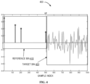
- FIG. 3A illustrates a schematic diagram of an example RPP 300 according to some example embodiments of the present disclosure.
- the RPP 300 obtained by the reader device 110 comprises respective power profile parts 301 to 303 in the first quiet period T P1 , the active period T A and the second quiet period T P2 .
- the power profile part 302 in the active period T A is substantially flat and non-negligible (e.g., above the first threshold), while the power profile parts 301 and 303 in the first and second quiet periods T P1 and T P2 are negligible (e.g., below the second threshold).
- the TT signal may be also heard by the attacker 130.
- the attacker 130-1 and the attacker 130-N may receive 225, 230 the TT signals.
- the attackers 130-1 to 130-N may transmit 235, 240 the attack signals. These attack signals may also reach the reader device 110 via respective channels. In particular, each of the attack signals may travel via a channel h x ( t ), which is determined as below.
- the RPP during the active period T may exhibit a step behavior. This is because the attackers 130-1 to 130-N act unsynchronized (i.e., with respect to the TT device 112), and have different locations. Therefore, their attacks will be observed at different moments in time as seen by the reader device 110.
- FIG. 3B illustrates a schematic diagram of another example RPP 310 according to some example embodiments of the present disclosure.
- the RPP 310 comprises the power profile part 311 in the first quiet period T P1 .
- the power profile part 311 is constant and below the second threshold.
- the power profile part in the active period T A comprises more than one power level.
- the power level 320 may correspond to the TT signal, and the power level 321 may correspond to an addition of the TT signal with the attack signal from the attacker 130.
- the power level 322 may correspond to the attack signal from the attacker 130.
- the power level 323 may be constant and below the second threshold.
- the reader device 110 determines 245 a number of attackers 130-1 to 130-N of the tag detection session based on the attack signal.
- the reader device 110 may determine 250 the number of the attacker 130 to be zero.
- the reader device 110 may increment 255 the number of the attackers 130 in a counter which may be integrated in the reader device or separate therefrom.
- the reader device 110 may be configured to log the number of steps for a subsequent reporting to the network device 120. The number of steps may be counted by using a counter that is expected to be proportional to the number of attackers 130.
- the reader device 110 may apply the following method which comprises the following main steps.
- the power profile of the active period T A may comprise power levels in a plurality of bins of the active period T A .
- dt is the shortest time to attack i.e., the time that an attacker would take to detect the TT signal, switch to transmission, and generate and transmit the attack signal, e.g., approximately 1 microsecond.
- a gap period standardized in TS 38.211 to allow the TX-RX switch is around 13 microseconds.
- a bin with index 0, i.e., b 0, expected to receive the first quiet period T P1 .
- bin 0 it may be convenient to detect simpler nonreactive jammers.
- operation (8) describes a standard envelope detection in which the CP is isolated from the TX signal.
- the remaining bins contain in addition to the TT signal, the attacker signals, therefore the operation (8) will return a noisy TT-reader channel, where the noise level depends on the power and number of attackers 130.
- the useful channel may be completely drowned in noise, and operation (8) will return only the noise power profile.
- the reader device 110 may check if the RPP is negligible during the first and second quiet periods T P1 and T P2 , and if the RPP exhibits a step behavior across bins corresponding to the active period T A , that is, if the RPP exhibits a step or a jump larger than a selected threshold between any two consecutive samples.
- the jump may be positive or negative.
- the reader device 110 may analyze the CP. For example, the reader device 110 may count the number of relevant taps (i.e., entries in the vector CP(b) with a value being above a threshold) in each bin, and compute a sparsity metric, for example, a bin sparsity metric S(b).
- the sparsity of a channel is a property of the channel impulse response when the channel is observed to exhibit a small number of multipath components.
- the reader device 110 may determine the number of attackers 130 to be zero.
- the channel sparsity may refer to a property of a channel impulse response when said channel is observed to exhibit a small number of multipath components.
- FIG. 4 illustrates a schematic diagram of a comparison 400 of a CP in the reference bin 410 with a CP in a target bin 420 contaminated by an attack according to some example embodiments of the present disclosure. As shown in FIG. 4 , the reference bin 410 and the target bin 420 have different sparsity.
- the metrics in the above operation (8) expresses the CP in a certain bin (e.g., CP (b)) with a distribution of the channel energy on different paths in a "delay" domain.
- CP(b) may be expressed with a distribution of the channel energy in a "spatial" domain, which tries to exploit different angles of arrivals (AoAs) of different paths.
- the function f represents a channel estimation algorithm.
- Such a channel estimation algorithm can be implemented by using a de-correlator as in operation (8), but other methods can also be used.
- the reader device 110 may compute a channel frequency response H n ( b ) from the time domain representation h n ( b ) for each antenna n.
- R(b) e.g., of size N ⁇ N
- R b H 1 b ; H 2 b ; ... ; H N b ⁇ H 1 b ; H 2 b ; ... ; H N b H
- CP(b) U b ⁇ b 1 / 2
- CP(b) is a matrix with each column representing a spatial direction from which some energy is received at the reader device 110.
- metric in operation (12) may be beneficial for example in a scenario where a lot of scatterers are around the reader device 110, so that the channel may be characterized by many paths, but all have a similar delay, i.e., they cannot be distinguished by using metric in operation (8), but can be separated because of their different AoA with a metric in operation (12).
- the number of the attackers 130 may be determined based on the power profile of the attack signal alone, or based on a combination of the power profile and the channel profile of the attack signal.
- the present disclosure is not limited in this regard.
- the reader device 110 then transmits 260 attacker information at least comprising the number of attackers 130-1 to 130-N to the network device 120.
- the attacker information may further comprise a size of at least one step in the power profile part in the active period T.
- the size of the at least one step may be a difference between a first power level of a first bin and a second power level of a second bin, where the first bin and the second bin are consecutive bins.
- the tag reader is able to identify the attacks that intend to block or jam tag sessions, and report attacker information to the NR network.
- This information helps the NR network to detect the attacks of ambient IoTs and take appropriate measures to ensure the integrity of the tag detection.
- network performances and communication reliability can be improved.
- FIG. 5 shows a flowchart of an example method 500 implemented at an apparatus in accordance with some example embodiments of the present disclosure.
- the apparatus may be a tag reader, such as a gNB, a UE, etc.
- the method 500 will be described from the perspective of the reader device 110 in FIG. 1 .
- the apparatus receives at least one signal which is at least associated with a trick tag signal transmitted from a terminal device.
- the terminal device may act as the TT device 112 as shown in FIG. 1 .
- the apparatus determines a number of attackers of a tag detection session based on the at least one signal.
- the apparatus transmits, to a network device, attacker information at least comprising the number of attackers.
- the network device may be a gNB, for example, the network device 130 as shown in FIG. 1 .
- the method 500 may further comprise: obtaining a power profile of the at least one signal, the power profile comprising power profile parts in a first quiet period, an active period, and a second quiet period; and determining the number of attackers based on the power profile.
- the method 500 may further comprise: in accordance with a determination that the power profile part in the active period is above a first threshold and flat, and the power profile parts in the first and second quiet periods are below a second threshold, determining the number of attackers to be zero. It is to be understood that as in real life operations a power profile might not be completely flat due to the fact that devices may not operate in an ideal manner. Hence, herein, reference to flat power profile part in the active period may refer to a power profile part that is substantially flat or approximately flat.
- the method 500 may further comprise: in accordance with a determination that there is a step in the power profile part in the active period, incrementing the count of the number of attackers.
- the power profile part in the first quiet period may be below a second threshold, and the power profile part in the second quiet period is above the second threshold.
- the method 500 may further comprise: in accordance with a determination that a difference between a first power level of a first bin and a second power level of a second bin is larger than a third threshold, determining that there is the step in the power profile part in the active period, the first bin and the second bin being consecutive bins.
- the attacker information may further comprise a size of at least one step in the power profile part in the active period.
- the method 500 may further comprise: obtaining a channel profile of the at least one signal, the channel profile at least comprising channel profile parts in a plurality of bins of an active period; determining sparsity metrics for the plurality of bins based on the channel profile parts; and determining the number of attackers based on the sparsity metrics.
- the method 500 may further comprise: comparing sparsity metrics of the plurality of bins with a reference sparsity metric of a reference bin affected by the trick tag signal; and in accordance with a determination that all of the sparsity metrics are the same as the reference sparsity metric, determining the number of attackers to be zero.
- the method 500 may further comprise: comparing a first sparsity metric of a first bin in the plurality of bins with a reference sparsity metric of a reference bin affected by the trick tag signal; and in accordance with a determination that the first sparsity metric is different from the reference sparsity metric, incrementing the count corresponding to the number of attackers.
- the method 500 may further comprise: obtaining a power profile of the at least one signal, the power profile comprising power profile parts in a first quiet period, an active period, and a second quiet period; obtaining a channel profile of the at least one signal, the channel profile at least comprising channel profile parts in a plurality of bins of the active period; and determining the number of attackers based on the power profile and the channel profile.
- the method 500 may further comprise: in accordance with a determination that the power profile part in the active period is above a first threshold and flat (or substantially flat), and the power profile parts in the first and second quiet periods are below a second threshold, comparing sparsity metrics of the plurality of bins with a reference sparsity metric of a reference bin affected by the trick tag signal; and in accordance with a determination that all the sparsity metrics are the same as the reference sparsity metric, determining the number of attackers to be zero.
- the method 500 may further comprise: in accordance with a determination that there is a step in the power profile part in the active period, comparing a sparsity metric of a third bin associated with the step in the plurality of bins with a reference sparsity metric of a reference bin affected by the trick tag signal; and in accordance with a determination that the sparsity metric of the third bin is different from the reference sparsity metric, incrementing the count of the number of attackers.
- the at least one signal may comprise a plurality of signals, and each of the plurality of the signals is received through a respective one of a plurality of antennas of the apparatus.
- the method 500 may further comprise: receiving, from the network device, a configuration indicative of a first quiet period, an active period, and a second quiet period of the trick tag signal.
- the apparatus may be a further terminal device or a further network device.
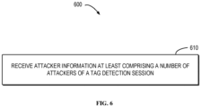
- FIG. 6 shows a flowchart of an example method 600 implemented at an apparatus in accordance with some example embodiments of the present disclosure.
- the apparatus may be a network device, such as, a gNB.
- the method 600 will be described from the perspective of the network device 120 in FIG. 1 .
- the apparatus receives, from a device, attacker information at least comprising a number of attackers of a tag detection session.
- the number of attackers is determined based on at least one signal received at the device, and the at least one signal is at least associated with a trick tag signal transmitted from a terminal device.
- the attacker information may further comprise a size of at least one step in a power profile part in an active period, and the power profile part is a part of a power profile of the at least one signal.
- the method 600 may further comprise: transmitting, to the device, a configuration indicative of a first quiet period, an active period, and a second quiet period of the trick tag signal.
- the apparatus may be a network device, and the device may be a further terminal device or a further network device.
- an apparatus which is also referred to as a first apparatus hereafter, capable of performing any of the method 500 (for example, the reader device 110 in FIG. 1 ) may comprise means for performing the respective operations of the method 500.
- the means may be implemented in any suitable form.
- the means may be implemented in a circuitry or software module.
- the first apparatus may be implemented as or included in the reader device 110 in FIG. 1 .
- the first apparatus comprises means for receiving at least one signal which is at least associated with a trick tag signal transmitted from a terminal device; means for determining a number of attackers of a tag detection session based on the at least one signal; and means for transmitting, to a network device, attacker information at least comprising the number of attackers.
- the first apparatus further comprises: means for obtaining a power profile of the at least one signal, the power profile comprising power profile parts in a first quiet period, an active period, and a second quiet period; and means for determining the number of attackers based on the power profile.
- the first apparatus further comprises: means for in accordance with a determination that the power profile part in the active period is above a first threshold and flat (or substantially flat), and the power profile parts in the first and second quiet periods are below a second threshold, determining the number of attackers to be zero.
- the first apparatus further comprises: means for in accordance with a determination that there is a step in the power profile part in the active period, incrementing the count of the number of attackers.
- the power profile part in the first quiet period is below a second threshold, and the power profile part in the second quiet period is above the second threshold.
- the first apparatus further comprises: means for in accordance with a determination that a difference between a first power level of a first bin and a second power level of a second bin is larger than a third threshold, determining that there is the step in the power profile part in the active period, the first bin and the second bin being consecutive bins.
- the attacker information further comprises a size of at least one step in the power profile part in the active period.
- the first apparatus further comprises: means for obtaining a channel profile of the at least one signal, the channel profile at least comprising channel profile parts in a plurality of bins of an active period; means for determining sparsity metrics for the plurality of bins based on the channel profile parts; and means for determining the number of attackers based on the sparsity metrics.
- the first apparatus further comprises: means for comparing sparsity metrics of the plurality of bins with a reference sparsity metric of a reference bin affected by the trick tag signal; and means for in accordance with a determination that all of the sparsity metrics are the same as the reference sparsity metric, determining the number of attackers to be zero.
- the first apparatus further comprises: means for comparing a first sparsity metric of a first bin in the plurality of bins with a reference sparsity metric of a reference bin affected by the trick tag signal; and means for in accordance with a determination that the first sparsity metric is different from the reference sparsity metric, incrementing the count of the number of attackers.
- the first apparatus further comprises: means for obtaining a power profile of the at least one signal, the power profile comprising power profile parts in a first quiet period, an active period, and a second quiet period; means for obtaining a channel profile of the at least one signal, the channel profile at least comprising channel profile parts in a plurality of bins of the active period; and means for determining the number of attackers based on the power profile and the channel profile.
- the first apparatus further comprises: means for in accordance with a determination that the power profile part in the active period is above a first threshold and flat (or substantially flat), and the power profile parts in the first and second quiet periods are below a second threshold, comparing sparsity metrics of the plurality of bins with a reference sparsity metric of a reference bin affected by the trick tag signal; and means for in accordance with a determination that all the sparsity metrics are the same as the reference sparsity metric, determining the number of attackers to be zero.
- the first apparatus further comprises: means for in accordance with a determination that there is a step in the power profile part in the active period, comparing a sparsity metric of a third bin associated with the step in the plurality of bins with a reference sparsity metric of a reference bin affected by the trick tag signal; and means for in accordance with a determination that the sparsity metric of the third bin is different from the reference sparsity metric, incrementing the count of the number of attackers.
- the at least one signal comprises a plurality of signals, and each of the plurality of the signals is received through a respective one of a plurality of antennas of the apparatus.
- the first apparatus further comprises: means for receiving, from the network device, a configuration indicative of a first quiet period, an active period, and a second quiet period of the trick tag signal.
- the first apparatus is a further terminal device or a further network device.
- the first apparatus further comprises means for performing other operations as described in the example embodiments of the method 500 or the reader device 110.
- the means comprises at least one processor; and at least one memory storing instructions that, when executed by the at least one processor, cause the performance of the first apparatus as disclosed herein.
- an apparatus also referred to as a second apparatus, capable of performing any of the method 600 (for example, the network device 120 in FIG. 1 ) may comprise means for performing the respective operations of the method 600.
- the means may be implemented in any suitable form.
- the means may be implemented in a circuitry or software module.
- the second apparatus may be implemented as or included in the network device 120 in FIG. 1 .
- the second apparatus comprises means for receiving, from a device, attacker information at least comprising a number of attackers of a tag detection session, wherein the number of attackers is determined based on at least one signal received at the device, and the at least one signal is at least associated with a trick tag signal transmitted from a terminal device.
- the attacker information further comprises a size of at least one step in a power profile part in an active period, and the power profile part is a part of a power profile of the at least one signal.
- the second apparatus further comprises: means for transmitting, to the device, a configuration indicative of a first quiet period, an active period, and a second quiet period of the trick tag signal.
- the second apparatus is a network device, and the device is a further terminal device or a further network device.
- the second apparatus further comprises means for performing other operations as described in some example embodiments of the method 600 or the network device 120.
- the means comprises at least one processor; and at least one memory storing instructions that, when executed by the at least one processor, cause the performance of the second apparatus.
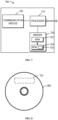
- FIG. 7 is a simplified block diagram of a device 700 that is suitable for implementing example embodiments of the present disclosure.
- the device 700 may be provided to implement a communication device, for example, the reader device 110, the TT device 112, or the network device 120 as shown in FIG. 1 .
- the device 700 includes one or more processors 710, one or more memories 720 coupled to the processor 710, and one or more communication modules 740 coupled to the processor 710.
- the communication module 740 is for bidirectional communications.
- the communication module 740 has one or more communication interfaces to facilitate communication with one or more other modules or devices.
- the communication interfaces may represent any interface that is necessary for communication with other network elements.
- the communication module 740 may include at least one antenna.
- the processor 710 may be of any type suitable to the local technical network and may include one or more of the following: general purpose computers, special purpose computers, microprocessors, digital signal processors (DSPs) and processors based on multicore processor architecture, as non-limiting examples.
- the device 700 may have multiple processors, such as an application specific integrated circuit chip that is slaved in time to a clock which synchronizes the main processor.
- the memory 720 may include one or more non-volatile memories and one or more volatile memories.
- the non-volatile memories include, but are not limited to, a Read Only Memory (ROM) 724, an electrically programmable read only memory (EPROM), a flash memory, a hard disk, a compact disc (CD), a digital video disk (DVD), an optical disk, a laser disk, and other magnetic storage and/or optical storage.
- the volatile memories include, but are not limited to, a random access memory (RAM) 722 and other volatile memories that will not last in the power-down duration.
- a computer program 730 includes computer executable instructions that are executed by the associated processor 710.
- the instructions of the program 730 may include instructions for performing operations/acts of some example embodiments of the present disclosure.
- the program 730 may be stored in the memory, e.g., the ROM 724.
- the processor 710 may perform any suitable actions and processing by loading the program 730 into the RAM 722.
- the example embodiments of the present disclosure may be implemented by means of the program 730 so that the device 700 may perform any process of the disclosure as discussed with reference to FIG. 2 to FIG. 6 .
- the example embodiments of the present disclosure may also be implemented by hardware or by a combination of software and hardware.
- the program 730 may be tangibly contained in a computer readable medium which may be included in the device 700 (such as in the memory 720) or other storage devices that are accessible by the device 700.
- the device 700 may load the program 730 from the computer readable medium to the RAM 722 for execution.
- the computer readable medium may include any types of non-transitory storage medium, such as ROM, EPROM, a flash memory, a hard disk, CD, DVD, and the like.
- non-transitory is a limitation of the medium itself (i.e., tangible, not a signal) as opposed to a limitation on data storage persistency (e.g., RAM vs. ROM).
- FIG. 8 shows an example of the computer readable medium 800 which may be in form of CD, DVD or other optical storage disk.
- the computer readable medium 800 has the program 730 stored thereon.
- various embodiments of the present disclosure may be implemented in hardware or special purpose circuits, software, logic or any combination thereof. Some aspects may be implemented in hardware, while other aspects may be implemented in firmware or software which may be executed by a controller, microprocessor or other computing device. While various aspects of embodiments of the present disclosure are illustrated and described as block diagrams, flowcharts, or using some other pictorial representations, it is to be understood that the block, apparatus, system, technique or method described herein may be implemented in, as non-limiting examples, hardware, software, firmware, special purpose circuits or logic, general purpose hardware or controller or other computing devices, or some combination thereof.
- Some example embodiments of the present disclosure also provide at least one computer program product tangibly stored on a computer readable medium, such as a non-transitory computer readable medium.
- the computer program product includes computer-executable instructions, such as those included in program modules, being executed in a device on a target physical or virtual processor, to carry out any of the methods as described above.
- program modules include routines, programs, libraries, objects, classes, components, data structures, or the like that perform particular tasks or implement particular abstract data types.
- the functionality of the program modules may be combined or split between program modules as desired in various embodiments.
- Machine-executable instructions for program modules may be executed within a local or distributed device. In a distributed device, program modules may be located in both local and remote storage media.
- Program code for carrying out methods of the present disclosure may be written in any combination of one or more programming languages.
- the program code may be provided to a processor or controller of a general purpose computer, special purpose computer, or other programmable data processing apparatus, such that the program code, when executed by the processor or controller, cause the functions/operations specified in the flowcharts and/or block diagrams to be implemented.
- the program code may execute entirely on a machine, partly on the machine, as a stand-alone software package, partly on the machine and partly on a remote machine or entirely on the remote machine or server.
- the computer program code or related data may be carried by any suitable carrier to enable the device, apparatus or processor to perform various processes and operations as described above.
- Examples of the carrier include a signal, computer readable medium, and the like.
- the computer readable medium may be a computer readable signal medium or a computer readable storage medium.
- a computer readable medium may include but not limited to an electronic, magnetic, optical, electromagnetic, infrared, or semiconductor system, apparatus, or device, or any suitable combination of the foregoing. More specific examples of the computer readable storage medium would include an electrical connection having one or more wires, a portable computer diskette, a hard disk, a random access memory (RAM), a read-only memory (ROM), an erasable programmable read-only memory (EPROM or Flash memory), an optical fiber, a portable compact disc read-only memory (CD-ROM), an optical storage device, a magnetic storage device, or any suitable combination of the foregoing.
Landscapes
- Engineering & Computer Science (AREA)
- Computer Networks & Wireless Communication (AREA)
- Signal Processing (AREA)
- Computer Security & Cryptography (AREA)
- Computing Systems (AREA)
- Remote Sensing (AREA)
- Radar, Positioning & Navigation (AREA)
- Computer Hardware Design (AREA)
- General Engineering & Computer Science (AREA)
- Electromagnetism (AREA)
- Microelectronics & Electronic Packaging (AREA)
- Physics & Mathematics (AREA)
- Mobile Radio Communication Systems (AREA)
Abstract
Description
- Various example embodiments of the present disclosure generally relate to the field of telecommunication and in particular, to methods, devices, apparatuses and computer readable storage media for attacker detection in ambient Internet of Things (IoT).
- In 5G NR, IoT technology has evolved to be suitable for cellular deployment. Such IoT technology may rely on ultra-low complexity devices with ultra-low power consumption for the very-low end IoT applications. In terms of energy storage, two types of IoT devices are considered, that is, pure batteryless devices and devices with energy storage capability. In particular, the batteryless devices are with no energy storage capability, and completely dependent on the availability of the ambient source of energy it is harvesting. The devices with energy storage capability are supplied by ambient sources via energy harvesting, and thus may not need to be replaced or recharged manually and can manage a short period of ambient energy unavailability.
- Those IoT devices are to be detected via a tag detection session. However, in the cellular-based deployment, there may be fraudulent devices intended to block or jam passive tag signals from reaching a tag reader. For example, the fraudulent devices may disturb the tag detection session by proactively or reactively emitting malicious or jamming signals, so that the NR network is prevented from acquiring tag information, and ultimately compromising the detection integrity.
- In a first aspect of the present disclosure, there is provided an apparatus. The apparatus comprises at least one processor; and at least one memory storing instructions that, when executed by the at least one processor, cause the apparatus at least to perform: receive at least one signal which is at least associated with a trick tag signal transmitted from a terminal device; determine a number of attackers of a tag detection session based on the at least one signal; and transmit, to a network device, attacker information at least comprising the number of attackers.
- In a second aspect of the present disclosure, there is provided an apparatus. The apparatus comprises at least one processor; and at least one memory storing instructions that, when executed by the at least one processor, cause the apparatus at least to perform: receive, from a device, attacker information at least comprising a number of attackers of a tag detection session, wherein the number of attackers is determined based on at least one signal received at the device, and the at least one signal is at least associated with a trick tag signal transmitted from a terminal device.
- In a third aspect of the present disclosure, there is provided a method. The method comprises: receiving at least one signal which is at least associated with a trick tag signal transmitted from a terminal device; determining a number of attackers of a tag detection session based on the at least one signal; and transmitting, to a network device, attacker information at least comprising the number of attackers.
- In a fourth aspect of the present disclosure, there is provided a method. The method comprises: receiving, from a device, attacker information at least comprising a number of attackers of a tag detection session, wherein the number of attackers is determined based on at least one signal received at the device, and the at least one signal is at least associated with a trick tag signal transmitted from a terminal device.
- In a fifth aspect of the present disclosure, there is provided an apparatus. The apparatus comprises means for receiving at least one signal which is at least associated with a trick tag signal transmitted from a terminal device; means for determining a number of attackers of a tag detection session based on the at least one signal; and means for transmitting, to a network device, attacker information at least comprising the number of attackers.
- In a sixth aspect of the present disclosure, there is provided an apparatus. The apparatus comprises means for receiving, from a device, attacker information at least comprising a number of attackers of a tag detection session, wherein the number of attackers is determined based on at least one signal received at the device, and the at least one signal is at least associated with a trick tag signal transmitted from a terminal device.
- In a seventh aspect of the present disclosure, there is provided a computer readable medium. The computer readable medium comprises instructions stored thereon for causing an apparatus to perform at least the method according to the third aspect.
- In an eighth aspect of the present disclosure, there is provided a computer readable medium. The computer readable medium comprises instructions stored thereon for causing an apparatus to perform at least the method according to the fourth aspect.
- It is to be understood that the Summary section is not intended to identify key or essential features of embodiments of the present disclosure, nor is it intended to be used to limit the scope of the present disclosure. Other features of the present disclosure will become easily comprehensible through the following description.
- Some example embodiments will now be described with reference to the accompanying drawings, where:
-
FIG. 1 illustrates an example communication environment in which example embodiments of the present disclosure can be implemented; -
FIG. 2 illustrates a signaling chart for communication according to some example embodiments of the present disclosure; -
FIG. 3A illustrates a schematic diagram of an example RPP according to some example embodiments of the present disclosure; -
FIG. 3B illustrates a schematic diagram of another example RPP according to some example embodiments of the present disclosure; -
FIG. 4 illustrates a schematic diagram of a comparison of a channel profile (CP) in reference bin with a CP in a target bin contaminated by an attack according to some example embodiments of the present disclosure; -
FIG. 5 illustrates a flowchart of a method implemented at an apparatus according to some example embodiments of the present disclosure; -
FIG. 6 illustrates a flowchart of a method implemented at an apparatus according to some example embodiments of the present disclosure; -
FIG. 7 illustrates a simplified block diagram of a device that is suitable for implementing example embodiments of the present disclosure; and -
FIG. 8 illustrates a block diagram of an example computer readable medium in accordance with some example embodiments of the present disclosure. - Throughout the drawings, the same or similar reference numerals represent the same or similar element.
- Principles of the present disclosure will now be described with reference to some example embodiments. It is to be understood that these embodiments are described only for the purpose of illustration and help those skilled in the art to understand and implement the present disclosure, without suggesting any limitation as to the scope of the disclosure. Embodiments described herein can be implemented in various manners other than the ones described below.
- In the following description and claims, unless defined otherwise, all technical and scientific terms used herein have the same meaning as commonly understood by one of ordinary skills in the art to which this disclosure belongs.
- References in the present disclosure to "one embodiment," "an embodiment," "an example embodiment," and the like indicate that the embodiment described may include a particular feature, structure, or characteristic, but it is not necessary that every embodiment includes the particular feature, structure, or characteristic. Moreover, such phrases are not necessarily referring to the same embodiment. Further, when a particular feature, structure, or characteristic is described in connection with an embodiment, it is submitted that it is within the knowledge of one skilled in the art to affect such feature, structure, or characteristic in connection with other embodiments whether or not explicitly described.
- It shall be understood that although the terms "first," "second" and the like may be used herein to describe various elements, these elements should not be limited by these terms. These terms are only used to distinguish one element from another. For example, a first element could be termed a second element, and similarly, a second element could be termed a first element, without departing from the scope of example embodiments. As used herein, the term "and/or" includes any and all combinations of one or more of the listed terms.
- As used herein, "at least one of the following: <a list of two or more elements>" and "at least one of <a list of two or more elements>" and similar wording, where the list of two or more elements are joined by "and" or "or", mean at least any one of the elements, or at least any two or more of the elements, or at least all the elements.
- As used herein, unless stated explicitly, performing a step "in response to A" does not indicate that the step is performed immediately after "A" occurs and one or more intervening steps may be included.
- The terminology used herein is for the purpose of describing particular embodiments only and is not intended to be limiting of example embodiments. As used herein, the singular forms "a", "an" and "the" are intended to include the plural forms as well, unless the context clearly indicates otherwise. It will be further understood that the terms "comprises", "comprising", "has", "having", "includes" and/or "including", when used herein, specify the presence of stated features, elements, and/or components etc., but do not preclude the presence or addition of one or more other features, elements, components and/ or combinations thereof.
- As used in this application, the term "circuitry" may refer to one or more or all of the following:
- (a) hardware-only circuit implementations (such as implementations in only analog and/or digital circuitry) and
- (b) combinations of hardware circuits and software, such as (as applicable):
- (i) a combination of analog and/or digital hardware circuit(s) with software/firmware and
- (ii) any portions of hardware processor(s) with software (including digital signal processor(s)), software, and memory(ies) that work together to cause an apparatus, such as a mobile phone or server, to perform various functions) and
- (c) hardware circuit(s) and or processor(s), such as a microprocessor(s) or a portion of a microprocessor(s), that requires software (e.g., firmware) for operation, but the software may not be present when it is not needed for operation.
- This definition of circuitry applies to all uses of this term in this application, including in any claims. As a further example, as used in this application, the term circuitry also covers an implementation of merely a hardware circuit or processor (or multiple processors) or portion of a hardware circuit or processor and its (or their) accompanying software and/or firmware. The term circuitry also covers, for example and if applicable to the particular claim element, a baseband integrated circuit or processor integrated circuit for a mobile device or a similar integrated circuit in server, a cellular network device, or other computing or network device.
- As used herein, the term "communication network" refers to a network following any suitable communication standards, such as New Radio (NR), Long Term Evolution (LTE), LTE-Advanced (LTE-A), Wideband Code Division Multiple Access (WCDMA), High-Speed Packet Access (HSPA), Narrow Band Internet of Things (NB-IoT) and so on. Furthermore, the communications between a terminal device and a network device in the communication network may be performed according to any suitable generation communication protocols, including, but not limited to, the first generation (1G), the second generation (2G), 2.5G, 2.75G, the third generation (3G), the fourth generation (4G), 4.5G, the fifth generation (5G) communication protocols, and/or any other protocols either currently known or to be developed in the future. Embodiments of the present disclosure may be applied in various communication systems. Given the rapid development in communications, there will of course also be future type communication technologies and systems with which the present disclosure may be embodied. It should not be seen as limiting the scope of the present disclosure to only the aforementioned system.
- As used herein, the term "network device" refers to a node in a communication network via which a terminal device accesses the network and receives services therefrom. The network device may refer to a base station (BS) or an access point (AP), for example, a node B (NodeB or NB), an evolved NodeB (eNodeB or eNB), an NR NB (also referred to as a gNB), a Remote Radio Unit (RRU), a radio header (RH), a remote radio head (RRH), a relay, an Integrated Access and Backhaul (IAB) node, a low power node such as a femto, a pico, a non-terrestrial network (NTN) or non-ground network device such as a satellite network device, a low earth orbit (LEO) satellite and a geosynchronous earth orbit (GEO) satellite, an aircraft network device, and so forth, depending on the applied terminology and technology. In some example embodiments, radio access network (RAN) split architecture comprises a Centralized Unit (CU) and a Distributed Unit (DU) at an IAB donor node. An IAB node comprises a Mobile Terminal (IAB-MT) part that behaves like a UE toward the parent node, and a DU part of an IAB node behaves like a base station toward the next-hop IAB node.
- The term "terminal device" refers to any end device that may be capable of wireless communication. By way of example rather than limitation, a terminal device may also be referred to as a communication device, user equipment (UE), a Subscriber Station (SS), a Portable Subscriber Station, a Mobile Station (MS), or an Access Terminal (AT). The terminal device may include, but not limited to, a mobile phone, a cellular phone, a smart phone, voice over IP (VoIP) phones, wireless local loop phones, a tablet, a wearable terminal device, a personal digital assistant (PDA), portable computers, desktop computer, image capture terminal devices such as digital cameras, gaming terminal devices, music storage and playback appliances, vehicle-mounted wireless terminal devices, wireless endpoints, mobile stations, laptop-embedded equipment (LEE), laptop-mounted equipment (LME), USB dongles, smart devices, wireless customer-premises equipment (CPE), an Internet of Things (IoT) device, a watch or other wearable, a head-mounted display (HMD), a vehicle, a drone, a medical device and applications (e.g., remote surgery), an industrial device and applications (e.g., a robot and/or other wireless devices operating in an industrial and/or an automated processing chain contexts), a consumer electronics device, a device operating on commercial and/or industrial wireless networks, and the like. The terminal device may also correspond to a Mobile Termination (MT) part of an IAB node (e.g., a relay node). In the following description, the terms "terminal device", "communication device", "terminal", "user equipment" and "UE" may be used interchangeably.
- As used herein, the term "resource," "transmission resource," "resource block," "physical resource block" (PRB), "uplink resource," or "downlink resource" may refer to any resource for performing a communication, for example, a communication between a terminal device and a network device, such as a resource in time domain, a resource in frequency domain, a resource in space domain, a resource in code domain, or any other resource enabling a communication, and the like. In the following, unless explicitly stated, a resource in both frequency domain and time domain will be used as an example of a transmission resource for describing some example embodiments of the present disclosure. It is noted that example embodiments of the present disclosure are equally applicable to other resources in other domains.
- As used herein, the term "fraudulent device", "tag jammer", or "attacker" may refer to a device that emit jamming signals to disturb a tag reading session. The tag jammer may be either proactive or reactive. The proactive jammer emits the jamming signals regardless of whether any tags are active or even present in a coverage area of the tag jammer. The reactive jammer monitors bands, and listens for tag activities, e.g., either activation signals, or tag replies. As soon as such activities are detected in any of the monitored bands, the reactive jammer may start jamming the associated spectrum.
- As compared with the reactive jammers, the proactive jammers are less efficient and more easily detected. On the other hand, the reactive jammers are more aggressive, since they can concentrate their jamming powers in the resources that matter. Those tag jammers would severely threaten the integrity of tag detection in NR network.
- If the NR network is able to detect the tag jammers in time, and accurately determine the number of the jammers, it is possible to locate those attackers and ensure the integrity of tag detection accordingly. However, detecting jamming attacks is a challenging task mainly because it involves distinguishing malicious behaviors from legitimate bad link conditions (e.g., caused by interference, fading, impulsive noise, hidden node, etc.) that cause poor performance.
- According to the example embodiments of the present disclosure, there is provided a solution of attacker detection for ambient IoTs. In this solution, one NR network element (e.g., a UE) may act as a trick tag (TT) that emulates a tag to stimulate the attackers in the deployment. Another NR network element (e.g., a gNB or a UE) may act as a tag reader that observes a spectrum associated with the TT transmission and assesses whether the spectrum becomes polluted by additional signals, after the TT transmission has started. In this way, the tag reader can then profile the attackers of ambient IoTs. Such profiles may help the NR network against the attackers.
-
FIG. 1 illustrates anexample communication environment 100 in which example embodiments of the present disclosure can be implemented. Thecommunication environment 100 may be a communication network that supports IoT applications. Thecommunication environment 100 may comprise areader device 110, aTT device 112, and anetwork device 120. Thereader device 110, theTT device 112, and thenetwork device 120 may communicate with each other. It should be understood that in thecommunication environment 100, there may also be one or more tags and tag readers (not shown). - The
reader device 110 may be either a terminal device (e.g., UE) or a network device (e.g., a gNB) that acts as a tag reader. TheTT device 112 may be a terminal device (e.g., UE) that acts as a trick tag. In particular, theTT device 112 may mimic a tag to stimulate one or more attackers to react, so that thenetwork device 120 can identify the malicious activity. - In some example embodiments, the
TT device 112 may not wait for an activation signal, but transmit a tag signal as configured. This is done to avoid activating other random tags from also transmitting and thus hampering the attacker detection. Accordingly, thereader device 110 may monitor a spectrum for activation signal transmission and assesses whether the spectrum is polluted by additional signals. - Moreover, as shown in
FIG. 1 , there may be one or more attackers 130-1 to 130-N (collectively referred to asattacker 130 hereinafter) that attempt to disturb a tag detection/reading session in thecommunication environment 100. For example, theattacker 130 may emit a jamming signal intended to block or jam a spectrum on which tag signals are to be transmitted. - It should be understood that although multiple attackers are shown in
FIG. 1 , the embodiments of the present disclosure are also applicable to the case where only one attacker is present, i.e., N is an integer greater than or equal to 1. Therefore, the present disclosure is not limited in this regard. - In order to ensure the integrity of tag detection session, the
network device 120 may be interested in the number of the attackers. For example, thenetwork device 120 may be able to locate or at least determine a direction of theattack 130 relative to a network element in thecommunication network 100 based on the number of the attackers. In some example embodiments, the number of the attackers may be determined from at least a part of attacker detection procedure between thereader device 110 and theTT device 112, which will be described in detail below. - In the following, for the purpose of illustration, some example embodiments are described with the
reader device 110 operating as a terminal device, and theTT device 112 operating as a network device. However, in some example embodiments, operations described in connection with a terminal device may be implemented at a network device or other device, and operations described in connection with a network device may be implemented at a terminal device or other device. - In some example embodiments, if the
reader device 110 is a terminal device, a link from thenetwork device 120 to thereader device 110 is referred to as a downlink (DL), while a link from thereader device 110 to thenetwork device 120 is referred to as an uplink (UL). In DL, thenetwork device 120 is a transmitting (TX) device (or a transmitter) and thereader device 110 is a receiving (RX) device (or a receiver). In UL, thereader device 110 is a TX device (or a transmitter) and thenetwork device 120 is a RX device (or a receiver). - Communications in the
communication environment 100 may be implemented according to any proper communication protocol(s), comprising, but not limited to, cellular communication protocols of the first generation (1G), the second generation (2G), the third generation (3G), the fourth generation (4G), the fifth generation (5G), the sixth generation (6G), and the like, wireless local network communication protocols such as Institute for Electrical and Electronics Engineers (IEEE) 802.11 and the like, and/or any other protocols currently known or to be developed in the future. Moreover, the communication may utilize any proper wireless communication technology, comprising but not limited to: Code Division Multiple Access (CDMA), Frequency Division Multiple Access (FDMA), Time Division Multiple Access (TDMA), Frequency Division Duplex (FDD), Time Division Duplex (TDD), Multiple-Input Multiple-Output (MIMO), Orthogonal Frequency Division Multiple (OFDM), Discrete Fourier Transform spread OFDM (DFT-s-OFDM) and/or any other technologies currently known or to be developed in the future. - Example embodiments of the present disclosure will be described in detail below with reference to the accompanying drawings.
- Reference is now made to
FIG. 2 , which illustrates a signaling chart of anattacker detection process 200 according to some example embodiments of the present disclosure. For the purpose of discussion, reference is also made toFIG. 1 to describe theattacker detection process 200. - The
attacker detection process 200 may be implemented between thereader device 110, theTT device 112, and thenetwork device 120. In particular, theTT device 112 may transmit a TT signal, which is referred to as an initialization signal. Such a TT signal may stimulate theattacker 130 react, for example, transmitting at least one signal in response to the TT signal. On the other hand, thereader device 110 may monitor a spectrum associated with the TT signal transmission, and profile if any signal from theattacker 130 is present. It should be understood that theattacker detection process 200 is applicable to both a case that a single attacker (e.g., attacker 130-1) is present and a case that multiple attackers (e.g., attackers 130-1 to 130-N) are present. - To facilitate the
attacker detection process 200, thenetwork device 120 may configure 205 thereader device 110 with a TT signal configuration. Thenetwork device 110 may also configure 210 theTT device 112 with the same or analogous TT signal configuration. Thenetwork device 120 may either simultaneously or sequentially transmit the TT signal configuration to thereader device 110 and theTT device 112. - In some example embodiments, the
attacker detection process 200 may be triggered by the transmission of the TT signal configuration. The TT signal configuration may be transmitted over a secure link with theTT device 112 to prevent from being predicted by theattacker 130. - In addition, a location of the
TT device 112 relative to thereader device 110 may be predetermined or estimated prior to starting the attacker detection procedure. For example, if theTT device 112 and thereader device 110 are NR UEs in RRC_CONNECTED mode, their relative locations may be derived by thenetwork device 120 by using channel state information (CSI) obtained from primary synchronization signal (PSS), secondary synchronization signal (SSS), channel state information reference signal (CSI-RS), downlink positioning reference signal (DL PRS), uplink sounding reference signal (UL SRS), etc. Alternatively, theTT device 112 may be triggered to perform sidelink (SL) positioning with thereader device 110, that is, theTT device 112 is configured to transmit SL PRS that allow thereader device 110 to estimate the location of theTT device 112 and/or channel related parameters, e.g., propagation delay and path-loss. With the location information of theTT device 112, thereader device 110 is enabled to capture the total TT signal and not only later reflections. - The TT signal configuration may indicate at least the following parameters:
- • a first quiet period TP1, which may be regarded as an offset, and which, in some example embodiments, may have a duration of t1 (for example, ranges from 0 to a time point t1),
- • an active period TA during which the TT signal is to be transmitted in band B, carrier fc, and with power P, and which may have a duration of T, and
- • a second quiet period TP2 with zero power, which may have a duration of t2.
- Based on the TT signal configuration, the
TT device 112 may transmit the TT signal only in the active period TA, and mute in the first and second quiet periods TP1 and TP2, thus the TX power is zero. - The TT signal configuration for the
reader device 110 may also indicate an observation window (denoted by W) that starts at Tstart and ends at Tstop, i.e., W= [Tstart, Tstop]. Tstart ensures that thereader device 110 can start listening at the right time so that the entire TT signal is made available for analysis. In view of this, Tstart may be proportional to a distance between theTT device 112 and thereader device 110. - The observation window comprises at least the first quiet period TP1, the active period of TA, and the second quiet period of TP2. In other words, the observation window W lasts for at least Tt = t1+T+t2 (e.g., in seconds).
- The above configuration is given as one of various implementations of the TT signal. In some other example embodiments, it is possible to implement different variations of the TT signal, for instance without forcing the same TX power (e.g., the power P) for the whole active period T. As an example, the active period T may be divided in two halves, in the first T/2, the
TT device 110 may transmit with power P1, while in the second T/2 with power P2. - Other functions or variations can be implemented as well. This may be beneficial to the attacker detection, as more complex "power modulation" functions are more difficult to be predicted by the attacker(s).
- The
TT device 112 may then transmit TT signals based on the TT signal configuration. In some example embodiments, the TT signal, denoted by s(t), is determined as below:
- The TT signal may travel 215 to the
reader device 110 over a channel with impulse response h(t), which is determined as below:
TT device 112 relative to thereader device 110 has been computed by thenetwork device 120, the delay τ 0 is known. The second term of the equation (2) sums all other reflections. - In some example embodiments, since the
attacker 130 may be reactive, their attacks may be expected at thereader device 110 after the first reception of the TT signal. In this case, thereader device 110 may monitor 220 the spectrum (e.g., spectral resources) associated with the TT signal during the observation window W. - In some example embodiments, the
reader device 110 may measure the received power profile (RPP) for each of the intervals, i.e., the first quiet period TP1, the active period TA, and the second quiet period TP2. Depending on whether theattack 130 is present, different RPPs may be obtained by thereader device 110. - If no attacker is present, the RX signal should be dominated by the TT signal without jamming signals. In this case, the RPP during the active period T may be constant and non-negligible, for example, above a first threshold. In addition, the RPP during the first quiet period TP1 and the second quiet period TP2 may be negligible, e.g., below a second threshold (e.g., Pn ≥0).
-
FIG. 3A illustrates a schematic diagram of anexample RPP 300 according to some example embodiments of the present disclosure. As shown inFIG. 3A , there is a propagation delay between the transmission of TT signal at theTT device 112 and the reception of the TT signal at thereader device 110. Moreover, theRPP 300 obtained by thereader device 110 comprises respectivepower profile parts 301 to 303 in the first quiet period TP1, the active period TA and the second quiet period TP2. In particular, thepower profile part 302 in the active period TA is substantially flat and non-negligible (e.g., above the first threshold), while thepower profile parts - On the other hand, if at least one
attacker 130 is present in thecommunication network 100, the TT signal may be also heard by theattacker 130. Referring back toFIG. 2 , the attacker 130-1 and the attacker 130-N may receive 225, 230 the TT signals. In response, the attacker 130-1 and the attacker 130-N may start generating signals associated with the TT signal, which is also referred to as attack signals, denoted by ax (t), where x = 1: X. - Accordingly, the attackers 130-1 to 130-N may transmit 235, 240 the attack signals. These attack signals may also reach the
reader device 110 via respective channels. In particular, each of the attack signals may travel via a channel hx (t), which is determined as below.
- As previously mentioned, the attack signals may be expected at the
reader device 110 after the first reception of the TT signal, i.e., τ x0 ≫ τ 0, ∀x = 1: X. Therefore, in case that theattacker 130 is present, during the observation window W, thereader device 110 may observe a RX signal yet) as below:
- In this case, the RPP during the active period T may exhibit a step behavior. This is because the attackers 130-1 to 130-N act unsynchronized (i.e., with respect to the TT device 112), and have different locations. Therefore, their attacks will be observed at different moments in time as seen by the
reader device 110. -
FIG. 3B illustrates a schematic diagram of anotherexample RPP 310 according to some example embodiments of the present disclosure. There is also a propagation delay in the example ofFIG. 3B . As shown inFIG. 3B , theRPP 310 comprises thepower profile part 311 in the first quiet period TP1. For example, since no TT signal is received in the first quiet period TP1, thepower profile part 311 is constant and below the second threshold. There is a step in the power profile part in the active period TA. In other words, the power profile part in the active period TA comprises more than one power level. In the example shown inFIG. 3B , the power level 320 may correspond to the TT signal, and the power level 321 may correspond to an addition of the TT signal with the attack signal from theattacker 130. In addition, there is also a step in the power profile part in the second quiet period TP2. In particular, thepower level 322 may correspond to the attack signal from theattacker 130. As neither TT signal nor the attack signal is received, thepower level 323 may be constant and below the second threshold. - Accordingly, the
reader device 110 determines 245 a number of attackers 130-1 to 130-N of the tag detection session based on the attack signal. In some example embodiments, if the power profile part in the active period TA is substantially flat and non-negligible (e.g., above the first threshold), and the power profile parts in the first and second quiet periods TP1 and TP1 non-negligible (e.g., below the second threshold), as shown inFIG. 3A , thereader device 110 may determine 250 the number of theattacker 130 to be zero. - Otherwise, if there is a step behavior in the power profile part in the active period T, the
reader device 110may increment 255 the number of theattackers 130 in a counter which may be integrated in the reader device or separate therefrom. In some example embodiments, when such step behavior is identified, thereader device 110 may be configured to log the number of steps for a subsequent reporting to thenetwork device 120. The number of steps may be counted by using a counter that is expected to be proportional to the number ofattackers 130. - In some example embodiments, the
reader device 110 may determine the number of theattackers 130 based on the power profile. In particular, thereader device 110 may sample the RX signal every Ts, which is the sampling time of the system, and collect the samples in the vector, denoted by y, as below:
- Using the collected samples, the
reader device 110 may apply the following method which comprises the following main steps. - The power profile of the active period TA may comprise power levels in a plurality of bins of the active period TA. First, the
reader device 110 may split the vector y into B vectors or bins as below:
- Thus, bin b = 1 is expected to be a reference bin, i.e., a bin dominated by the TT signal. Before the B bins, there may also have a bin with
index 0, i.e., b=0, expected to receive the first quiet period TP1. Withbin 0, it may be convenient to detect simpler nonreactive jammers. - After binning the samples, for each bin b, where b = 1:B, the
reader device 110 may compute a vector of RPP, denoted by RPP(b), and a vector of channel profile (CP), denoted by CP(b), as below

- The reference bin b = 1 is expected to contain the sole TT signal, therefore the operation (8) will return the approximate channel delay profile for the TT-reader channel i.e., the useful channel. The remaining bins contain in addition to the TT signal, the attacker signals, therefore the operation (8) will return a noisy TT-reader channel, where the noise level depends on the power and number of
attackers 130. In the worst-case scenario, the useful channel may be completely drowned in noise, and operation (8) will return only the noise power profile. - Next, the
reader device 110 may check if the RPP is negligible during the first and second quiet periods TP1 and TP2, and if the RPP exhibits a step behavior across bins corresponding to the active period TA, that is, if the RPP exhibits a step or a jump larger than a selected threshold between any two consecutive samples. For example, the jump may be positive or negative. - If a jump is detected between two consecutive samples, then the
reader device 110 may increment an attacker counter c, e.g., c = c+1. Moreover, thereader device 110 may store a size of the jump. For example, thereader device 110 may compute a difference between the RPPs for the samples corresponding to the jump dp. In the context of the present disclosure, the size of the jump may be also referred to as a size of a step. It is to be understood that a size is related to a value corresponding to a measured power profile difference in any consecutive two RPPs. - Additionally, or alternatively, the
reader device 110 may analyze the CP. For example, thereader device 110 may count the number of relevant taps (i.e., entries in the vector CP(b) with a value being above a threshold) in each bin, and compute a sparsity metric, for example, a bin sparsity metric S(b). The sparsity of a channel is a property of the channel impulse response when the channel is observed to exhibit a small number of multipath components. - The
reader device 110 may compare the sparsity of each bin with index b > 2 with that of the reference bin with index b = 1. Thereader device 110 may then determine the number ofattackers 130 based on the sparsity metrics. For example, thereader device 110 may increment the counter c if both of the following conditions are met: - • an RPP jump is detected, and
- • a bin with sparsity different than that of the reference bin is found.
- Otherwise, if all of the sparsity metrics are the same as the sparsity metric of the reference bin, the
reader device 110 may determine the number ofattackers 130 to be zero. - In the context of the present disclosure, the channel sparsity may refer to a property of a channel impulse response when said channel is observed to exhibit a small number of multipath components.
FIG. 4 illustrates a schematic diagram of acomparison 400 of a CP in thereference bin 410 with a CP in atarget bin 420 contaminated by an attack according to some example embodiments of the present disclosure. As shown inFIG. 4 , thereference bin 410 and thetarget bin 420 have different sparsity. - The metrics in the above operation (8) expresses the CP in a certain bin (e.g., CP (b)) with a distribution of the channel energy on different paths in a "delay" domain. Alternatively, other metrics may be used for expressing CP(b). For example, if the
reader device 110 is equipped with multiple antennas, CP(b) may be expressed with a distribution of the channel energy in a "spatial" domain, which tries to exploit different angles of arrivals (AoAs) of different paths. - As an example, if the
reader device 110 is equipped with N antennas, for each bin b, it may estimate a channel between theTT device 112 and its n-th antenna as below:
reader device 110 receives N signals, one for each antenna. The function f represents a channel estimation algorithm. Such a channel estimation algorithm can be implemented by using a de-correlator as in operation (8), but other methods can also be used. - Then, the
reader device 110 may compute a channel frequency response Hn (b) from the time domain representation hn (b) for each antenna n. - After that, for each bin b, the
reader device 110 may estimate a covariance matrix R(b) (e.g., of size N × N),
- The
reader device 110 may also calculate its eigen-vector decomposition as below:
reader device 110. - Therefore, a potential expression for CP(b) can be expressed as below:

reader device 110. - Note that metric in operation (12) may be beneficial for example in a scenario where a lot of scatterers are around the
reader device 110, so that the channel may be characterized by many paths, but all have a similar delay, i.e., they cannot be distinguished by using metric in operation (8), but can be separated because of their different AoA with a metric in operation (12). - It should be understood that the number of the
attackers 130 may be determined based on the power profile of the attack signal alone, or based on a combination of the power profile and the channel profile of the attack signal. The present disclosure is not limited in this regard. - The
reader device 110 then transmits 260 attacker information at least comprising the number of attackers 130-1 to 130-N to thenetwork device 120. Additionally, in some example embodiments, the attacker information may further comprise a size of at least one step in the power profile part in the active period T. For example, the size of the at least one step may be a difference between a first power level of a first bin and a second power level of a second bin, where the first bin and the second bin are consecutive bins. - According to the example embodiments of the present disclosure, there is provided a solution of attacker detection in ambient IoTs. In this solution, the tag reader is able to identify the attacks that intend to block or jam tag sessions, and report attacker information to the NR network. This information helps the NR network to detect the attacks of ambient IoTs and take appropriate measures to ensure the integrity of the tag detection. Thus, network performances and communication reliability can be improved.
-
FIG. 5 shows a flowchart of anexample method 500 implemented at an apparatus in accordance with some example embodiments of the present disclosure. For example, the apparatus may be a tag reader, such as a gNB, a UE, etc. For the purpose of discussion, themethod 500 will be described from the perspective of thereader device 110 inFIG. 1 . - At
block 510, the apparatus receives at least one signal which is at least associated with a trick tag signal transmitted from a terminal device. - In some example embodiments, the terminal device may act as the
TT device 112 as shown inFIG. 1 . - At
block 520, the apparatus determines a number of attackers of a tag detection session based on the at least one signal. - At
block 530, the apparatus transmits, to a network device, attacker information at least comprising the number of attackers. In some example embodiments, the network device may be a gNB, for example, thenetwork device 130 as shown inFIG. 1 . - In some example embodiments, the
method 500 may further comprise: obtaining a power profile of the at least one signal, the power profile comprising power profile parts in a first quiet period, an active period, and a second quiet period; and determining the number of attackers based on the power profile. - In some example embodiments, the
method 500 may further comprise: in accordance with a determination that the power profile part in the active period is above a first threshold and flat, and the power profile parts in the first and second quiet periods are below a second threshold, determining the number of attackers to be zero. It is to be understood that as in real life operations a power profile might not be completely flat due to the fact that devices may not operate in an ideal manner. Hence, herein, reference to flat power profile part in the active period may refer to a power profile part that is substantially flat or approximately flat. - In some example embodiments, the
method 500 may further comprise: in accordance with a determination that there is a step in the power profile part in the active period, incrementing the count of the number of attackers. - In some example embodiments, the power profile part in the first quiet period may be below a second threshold, and the power profile part in the second quiet period is above the second threshold.
- In some example embodiments, the
method 500 may further comprise: in accordance with a determination that a difference between a first power level of a first bin and a second power level of a second bin is larger than a third threshold, determining that there is the step in the power profile part in the active period, the first bin and the second bin being consecutive bins. - In some example embodiments, the attacker information may further comprise a size of at least one step in the power profile part in the active period.
- In some example embodiments, the
method 500 may further comprise: obtaining a channel profile of the at least one signal, the channel profile at least comprising channel profile parts in a plurality of bins of an active period; determining sparsity metrics for the plurality of bins based on the channel profile parts; and determining the number of attackers based on the sparsity metrics. - In some example embodiments, the
method 500 may further comprise: comparing sparsity metrics of the plurality of bins with a reference sparsity metric of a reference bin affected by the trick tag signal; and in accordance with a determination that all of the sparsity metrics are the same as the reference sparsity metric, determining the number of attackers to be zero. - In some example embodiments, the
method 500 may further comprise: comparing a first sparsity metric of a first bin in the plurality of bins with a reference sparsity metric of a reference bin affected by the trick tag signal; and in accordance with a determination that the first sparsity metric is different from the reference sparsity metric, incrementing the count corresponding to the number of attackers. - In some example embodiments, the
method 500 may further comprise: obtaining a power profile of the at least one signal, the power profile comprising power profile parts in a first quiet period, an active period, and a second quiet period; obtaining a channel profile of the at least one signal, the channel profile at least comprising channel profile parts in a plurality of bins of the active period; and determining the number of attackers based on the power profile and the channel profile. - In some example embodiments, the
method 500 may further comprise: in accordance with a determination that the power profile part in the active period is above a first threshold and flat (or substantially flat), and the power profile parts in the first and second quiet periods are below a second threshold, comparing sparsity metrics of the plurality of bins with a reference sparsity metric of a reference bin affected by the trick tag signal; and in accordance with a determination that all the sparsity metrics are the same as the reference sparsity metric, determining the number of attackers to be zero. - In some example embodiments, the
method 500 may further comprise: in accordance with a determination that there is a step in the power profile part in the active period, comparing a sparsity metric of a third bin associated with the step in the plurality of bins with a reference sparsity metric of a reference bin affected by the trick tag signal; and in accordance with a determination that the sparsity metric of the third bin is different from the reference sparsity metric, incrementing the count of the number of attackers. - In some example embodiments, the at least one signal may comprise a plurality of signals, and each of the plurality of the signals is received through a respective one of a plurality of antennas of the apparatus.
- In some example embodiments, the
method 500 may further comprise: receiving, from the network device, a configuration indicative of a first quiet period, an active period, and a second quiet period of the trick tag signal. - In some example embodiments, the apparatus may be a further terminal device or a further network device.
-
FIG. 6 shows a flowchart of anexample method 600 implemented at an apparatus in accordance with some example embodiments of the present disclosure. For example, the apparatus may be a network device, such as, a gNB. For the purpose of discussion, themethod 600 will be described from the perspective of thenetwork device 120 inFIG. 1 . - At
block 610, the apparatus receives, from a device, attacker information at least comprising a number of attackers of a tag detection session. The number of attackers is determined based on at least one signal received at the device, and the at least one signal is at least associated with a trick tag signal transmitted from a terminal device. - In some example embodiments, the attacker information may further comprise a size of at least one step in a power profile part in an active period, and the power profile part is a part of a power profile of the at least one signal.
- In some example embodiments, the
method 600 may further comprise: transmitting, to the device, a configuration indicative of a first quiet period, an active period, and a second quiet period of the trick tag signal. - In some example embodiments, the apparatus may be a network device, and the device may be a further terminal device or a further network device.
- In some example embodiments, an apparatus, which is also referred to as a first apparatus hereafter, capable of performing any of the method 500 (for example, the
reader device 110 inFIG. 1 ) may comprise means for performing the respective operations of themethod 500. The means may be implemented in any suitable form. For example, the means may be implemented in a circuitry or software module. The first apparatus may be implemented as or included in thereader device 110 inFIG. 1 . - In some example embodiments, the first apparatus comprises means for receiving at least one signal which is at least associated with a trick tag signal transmitted from a terminal device; means for determining a number of attackers of a tag detection session based on the at least one signal; and means for transmitting, to a network device, attacker information at least comprising the number of attackers.
- In some example embodiments, the first apparatus further comprises: means for obtaining a power profile of the at least one signal, the power profile comprising power profile parts in a first quiet period, an active period, and a second quiet period; and means for determining the number of attackers based on the power profile.
- In some example embodiments, the first apparatus further comprises: means for in accordance with a determination that the power profile part in the active period is above a first threshold and flat (or substantially flat), and the power profile parts in the first and second quiet periods are below a second threshold, determining the number of attackers to be zero.
- In some example embodiments, the first apparatus further comprises: means for in accordance with a determination that there is a step in the power profile part in the active period, incrementing the count of the number of attackers.
- In some example embodiments, the power profile part in the first quiet period is below a second threshold, and the power profile part in the second quiet period is above the second threshold.
- In some example embodiments, the first apparatus further comprises: means for in accordance with a determination that a difference between a first power level of a first bin and a second power level of a second bin is larger than a third threshold, determining that there is the step in the power profile part in the active period, the first bin and the second bin being consecutive bins.
- In some example embodiments, the attacker information further comprises a size of at least one step in the power profile part in the active period.
- In some example embodiments, the first apparatus further comprises: means for obtaining a channel profile of the at least one signal, the channel profile at least comprising channel profile parts in a plurality of bins of an active period; means for determining sparsity metrics for the plurality of bins based on the channel profile parts; and means for determining the number of attackers based on the sparsity metrics.
- In some example embodiments, the first apparatus further comprises: means for comparing sparsity metrics of the plurality of bins with a reference sparsity metric of a reference bin affected by the trick tag signal; and means for in accordance with a determination that all of the sparsity metrics are the same as the reference sparsity metric, determining the number of attackers to be zero.
- In some example embodiments, the first apparatus further comprises: means for comparing a first sparsity metric of a first bin in the plurality of bins with a reference sparsity metric of a reference bin affected by the trick tag signal; and means for in accordance with a determination that the first sparsity metric is different from the reference sparsity metric, incrementing the count of the number of attackers.
- In some example embodiments, the first apparatus further comprises: means for obtaining a power profile of the at least one signal, the power profile comprising power profile parts in a first quiet period, an active period, and a second quiet period; means for obtaining a channel profile of the at least one signal, the channel profile at least comprising channel profile parts in a plurality of bins of the active period; and means for determining the number of attackers based on the power profile and the channel profile.
- In some example embodiments, the first apparatus further comprises: means for in accordance with a determination that the power profile part in the active period is above a first threshold and flat (or substantially flat), and the power profile parts in the first and second quiet periods are below a second threshold, comparing sparsity metrics of the plurality of bins with a reference sparsity metric of a reference bin affected by the trick tag signal; and means for in accordance with a determination that all the sparsity metrics are the same as the reference sparsity metric, determining the number of attackers to be zero.
- In some example embodiments, the first apparatus further comprises: means for in accordance with a determination that there is a step in the power profile part in the active period, comparing a sparsity metric of a third bin associated with the step in the plurality of bins with a reference sparsity metric of a reference bin affected by the trick tag signal; and means for in accordance with a determination that the sparsity metric of the third bin is different from the reference sparsity metric, incrementing the count of the number of attackers.
- In some example embodiments, the at least one signal comprises a plurality of signals, and each of the plurality of the signals is received through a respective one of a plurality of antennas of the apparatus.
- In some example embodiments, the first apparatus further comprises: means for receiving, from the network device, a configuration indicative of a first quiet period, an active period, and a second quiet period of the trick tag signal.
- In some example embodiments, the first apparatus is a further terminal device or a further network device.
- In some example embodiments, the first apparatus further comprises means for performing other operations as described in the example embodiments of the
method 500 or thereader device 110. In some example embodiments, the means comprises at least one processor; and at least one memory storing instructions that, when executed by the at least one processor, cause the performance of the first apparatus as disclosed herein. - In some example embodiments, an apparatus, also referred to as a second apparatus, capable of performing any of the method 600 (for example, the
network device 120 inFIG. 1 ) may comprise means for performing the respective operations of themethod 600. The means may be implemented in any suitable form. For example, the means may be implemented in a circuitry or software module. The second apparatus may be implemented as or included in thenetwork device 120 inFIG. 1 . - In some example embodiments, the second apparatus comprises means for receiving, from a device, attacker information at least comprising a number of attackers of a tag detection session, wherein the number of attackers is determined based on at least one signal received at the device, and the at least one signal is at least associated with a trick tag signal transmitted from a terminal device.
- In some example embodiments, the attacker information further comprises a size of at least one step in a power profile part in an active period, and the power profile part is a part of a power profile of the at least one signal.
- In some example embodiments, the second apparatus further comprises: means for transmitting, to the device, a configuration indicative of a first quiet period, an active period, and a second quiet period of the trick tag signal.
- In some example embodiments, the second apparatus is a network device, and the device is a further terminal device or a further network device.
- In some example embodiments, the second apparatus further comprises means for performing other operations as described in some example embodiments of the
method 600 or thenetwork device 120. In some example embodiments, the means comprises at least one processor; and at least one memory storing instructions that, when executed by the at least one processor, cause the performance of the second apparatus. -
FIG. 7 is a simplified block diagram of adevice 700 that is suitable for implementing example embodiments of the present disclosure. Thedevice 700 may be provided to implement a communication device, for example, thereader device 110, theTT device 112, or thenetwork device 120 as shown inFIG. 1 . As shown, thedevice 700 includes one ormore processors 710, one ormore memories 720 coupled to theprocessor 710, and one ormore communication modules 740 coupled to theprocessor 710. - The
communication module 740 is for bidirectional communications. Thecommunication module 740 has one or more communication interfaces to facilitate communication with one or more other modules or devices. The communication interfaces may represent any interface that is necessary for communication with other network elements. In some example embodiments, thecommunication module 740 may include at least one antenna. - The
processor 710 may be of any type suitable to the local technical network and may include one or more of the following: general purpose computers, special purpose computers, microprocessors, digital signal processors (DSPs) and processors based on multicore processor architecture, as non-limiting examples. Thedevice 700 may have multiple processors, such as an application specific integrated circuit chip that is slaved in time to a clock which synchronizes the main processor. - The
memory 720 may include one or more non-volatile memories and one or more volatile memories. Examples of the non-volatile memories include, but are not limited to, a Read Only Memory (ROM) 724, an electrically programmable read only memory (EPROM), a flash memory, a hard disk, a compact disc (CD), a digital video disk (DVD), an optical disk, a laser disk, and other magnetic storage and/or optical storage. Examples of the volatile memories include, but are not limited to, a random access memory (RAM) 722 and other volatile memories that will not last in the power-down duration. - A
computer program 730 includes computer executable instructions that are executed by the associatedprocessor 710. The instructions of theprogram 730 may include instructions for performing operations/acts of some example embodiments of the present disclosure. Theprogram 730 may be stored in the memory, e.g., theROM 724. Theprocessor 710 may perform any suitable actions and processing by loading theprogram 730 into theRAM 722. - The example embodiments of the present disclosure may be implemented by means of the
program 730 so that thedevice 700 may perform any process of the disclosure as discussed with reference toFIG. 2 to FIG. 6 . The example embodiments of the present disclosure may also be implemented by hardware or by a combination of software and hardware. - In some example embodiments, the
program 730 may be tangibly contained in a computer readable medium which may be included in the device 700 (such as in the memory 720) or other storage devices that are accessible by thedevice 700. Thedevice 700 may load theprogram 730 from the computer readable medium to theRAM 722 for execution. In some example embodiments, the computer readable medium may include any types of non-transitory storage medium, such as ROM, EPROM, a flash memory, a hard disk, CD, DVD, and the like. The term "non-transitory," as used herein, is a limitation of the medium itself (i.e., tangible, not a signal) as opposed to a limitation on data storage persistency (e.g., RAM vs. ROM). -
FIG. 8 shows an example of the computerreadable medium 800 which may be in form of CD, DVD or other optical storage disk. The computerreadable medium 800 has theprogram 730 stored thereon. - Generally, various embodiments of the present disclosure may be implemented in hardware or special purpose circuits, software, logic or any combination thereof. Some aspects may be implemented in hardware, while other aspects may be implemented in firmware or software which may be executed by a controller, microprocessor or other computing device. While various aspects of embodiments of the present disclosure are illustrated and described as block diagrams, flowcharts, or using some other pictorial representations, it is to be understood that the block, apparatus, system, technique or method described herein may be implemented in, as non-limiting examples, hardware, software, firmware, special purpose circuits or logic, general purpose hardware or controller or other computing devices, or some combination thereof.
- Some example embodiments of the present disclosure also provide at least one computer program product tangibly stored on a computer readable medium, such as a non-transitory computer readable medium. The computer program product includes computer-executable instructions, such as those included in program modules, being executed in a device on a target physical or virtual processor, to carry out any of the methods as described above. Generally, program modules include routines, programs, libraries, objects, classes, components, data structures, or the like that perform particular tasks or implement particular abstract data types. The functionality of the program modules may be combined or split between program modules as desired in various embodiments. Machine-executable instructions for program modules may be executed within a local or distributed device. In a distributed device, program modules may be located in both local and remote storage media.
- Program code for carrying out methods of the present disclosure may be written in any combination of one or more programming languages. The program code may be provided to a processor or controller of a general purpose computer, special purpose computer, or other programmable data processing apparatus, such that the program code, when executed by the processor or controller, cause the functions/operations specified in the flowcharts and/or block diagrams to be implemented. The program code may execute entirely on a machine, partly on the machine, as a stand-alone software package, partly on the machine and partly on a remote machine or entirely on the remote machine or server.
- In the context of the present disclosure, the computer program code or related data may be carried by any suitable carrier to enable the device, apparatus or processor to perform various processes and operations as described above. Examples of the carrier include a signal, computer readable medium, and the like.
- The computer readable medium may be a computer readable signal medium or a computer readable storage medium. A computer readable medium may include but not limited to an electronic, magnetic, optical, electromagnetic, infrared, or semiconductor system, apparatus, or device, or any suitable combination of the foregoing. More specific examples of the computer readable storage medium would include an electrical connection having one or more wires, a portable computer diskette, a hard disk, a random access memory (RAM), a read-only memory (ROM), an erasable programmable read-only memory (EPROM or Flash memory), an optical fiber, a portable compact disc read-only memory (CD-ROM), an optical storage device, a magnetic storage device, or any suitable combination of the foregoing.
- Further, while operations are depicted in a particular order, this should not be understood as requiring that such operations be performed in the particular order shown or in sequential order, or that all illustrated operations be performed, to achieve desirable results. In certain circumstances, multitasking and parallel processing may be advantageous. Likewise, while several specific implementation details are contained in the above discussions, these should not be construed as limitations on the scope of the present disclosure, but rather as descriptions of features that may be specific to particular embodiments. Unless explicitly stated, certain features that are described in the context of separate embodiments may also be implemented in combination in a single embodiment. Conversely, unless explicitly stated, various features that are described in the context of a single embodiment may also be implemented in a plurality of embodiments separately or in any suitable sub-combination.
- Although the present disclosure has been described in languages specific to structural features and/or methodological acts, it is to be understood that the present disclosure defined in the appended claims is not necessarily limited to the specific features or acts described above. Rather, the specific features and acts described above are disclosed as example forms of implementing the claims.
Claims (15)
- An apparatus comprising:means for receiving at least one signal which is at least associated with a trick tag signal transmitted from a terminal device;means for determining a number of attackers of a tag detection session based on the at least one signal; andmeans for transmitting, to a network device, attacker information at least comprising the number of attackers.
- The apparatus of claim 1, wherein the apparatus is further configured to:obtain a power profile of the at least one signal, the power profile comprising power profile parts in a first quiet period, an active period, and a second quiet period; anddetermine the number of attackers based on the power profile.
- The apparatus of claim 2, wherein the apparatus is further configured to:
in accordance with a determination that the power profile part in the active period is above a first threshold and substantially flat, and the power profile parts in the first and second quiet periods are below a second threshold, determine the number of attackers to be zero. - The apparatus of claim 2 or 3, wherein the apparatus is further configured to:
in accordance with a determination that there is a step in the power profile part in the active period, increment a count of the number of attackers. - The apparatus of claim 4, wherein the power profile part in the first quiet period is below a second threshold, and the power profile part in the second quiet period is above the second threshold.
- The apparatus of claim 4, wherein the power profile in the active period comprises power levels in a plurality of bins of an active period, and the apparatus is further configured to:
in accordance with a determination that a difference between a first power level of a first bin and a second power level of a second bin is larger than a third threshold, determine that there is the step in the power profile part in the active period, the first bin and the second bin being consecutive bins. - The apparatus of any of claims 4 to 6, wherein the attacker information further comprises a size of at least one step in the power profile part in the active period.
- The apparatus of claim 1, wherein the apparatus is further configured to:obtain a channel profile of the at least one signal, the channel profile at least comprising channel profile parts in a plurality of bins of an active period;determine sparsity metrics for the plurality of bins based on the channel profile parts; anddetermine the number of attackers based on the sparsity metrics.
- The apparatus of claim 1, wherein the apparatus is further configured to:obtain a power profile of the at least one signal, the power profile comprising power profile parts in a first quiet period, an active period, and a second quiet period;obtain a channel profile of the at least one signal, the channel profile at least comprising channel profile parts in a plurality of bins of the active period; anddetermine the number of attackers based on the power profile and the channel profile.
- The apparatus of any of claims 1 to 9, wherein the at least one signal comprises a plurality of signals, and each of the plurality of the signals is received through a respective one of a plurality of antennas of the apparatus.
- The apparatus of any of claims 1 to 10, wherein the apparatus is a further terminal device or a further network device.
- An apparatus comprising:means for receiving, from a device, attacker information at least comprising a number of attackers of a tag detection session,wherein the number of attackers is determined based on at least one signal received at the device, and the at least one signal is at least associated with a trick tag signal transmitted from a terminal device.
- A method comprising:receiving at least one signal which is at least associated with a trick tag signal transmitted from a terminal device;determining a number of attackers of a tag detection session based on the at least one signal; andtransmitting, to a network device, attacker information at least comprising the number of attackers.
- A method comprising:receiving, from a device, attacker information at least comprising a number of attackers of a tag detection session,wherein the number of attackers is determined based on at least one signal received at the device, and the at least one signal is at least associated with a trick tag signal transmitted from a terminal device.
- A computer readable medium comprising instructions stored thereon for causing an apparatus at least to perform the method of claim 13 or the method of claim 14.
Applications Claiming Priority (1)
| Application Number | Priority Date | Filing Date | Title |
|---|---|---|---|
| GB2303502.5A GB2627975A (en) | 2023-03-10 | 2023-03-10 | Attacker detection in ambient IoT |
Publications (2)
| Publication Number | Publication Date |
|---|---|
| EP4429297A1 true EP4429297A1 (en) | 2024-09-11 |
| EP4429297B1 EP4429297B1 (en) | 2025-12-24 |
Family
ID=86052595
Family Applications (1)
| Application Number | Title | Priority Date | Filing Date |
|---|---|---|---|
| EP24161130.0A Active EP4429297B1 (en) | 2023-03-10 | 2024-03-04 | Attacker detection in ambient iot |
Country Status (3)
| Country | Link |
|---|---|
| US (1) | US20240305652A1 (en) |
| EP (1) | EP4429297B1 (en) |
| GB (1) | GB2627975A (en) |
Citations (2)
| Publication number | Priority date | Publication date | Assignee | Title |
|---|---|---|---|---|
| WO2021258382A1 (en) * | 2020-06-25 | 2021-12-30 | Nokia Shanghai Bell Co., Ltd. | Reactive jamming detection |
| US20230057179A1 (en) * | 2021-08-20 | 2023-02-23 | Ford Global Technologies, Llc | Collaborative signal jamming detection |
Family Cites Families (1)
| Publication number | Priority date | Publication date | Assignee | Title |
|---|---|---|---|---|
| US9000892B2 (en) * | 2011-10-31 | 2015-04-07 | Eastman Kodak Company | Detecting RFID tag and inhibiting skimming |
-
2023
- 2023-03-10 GB GB2303502.5A patent/GB2627975A/en active Pending
-
2024
- 2024-03-01 US US18/592,733 patent/US20240305652A1/en active Pending
- 2024-03-04 EP EP24161130.0A patent/EP4429297B1/en active Active
Patent Citations (2)
| Publication number | Priority date | Publication date | Assignee | Title |
|---|---|---|---|---|
| WO2021258382A1 (en) * | 2020-06-25 | 2021-12-30 | Nokia Shanghai Bell Co., Ltd. | Reactive jamming detection |
| US20230057179A1 (en) * | 2021-08-20 | 2023-02-23 | Ford Global Technologies, Llc | Collaborative signal jamming detection |
Also Published As
| Publication number | Publication date |
|---|---|
| US20240305652A1 (en) | 2024-09-12 |
| GB2627975A (en) | 2024-09-11 |
| GB202303502D0 (en) | 2023-04-26 |
| EP4429297B1 (en) | 2025-12-24 |
Similar Documents
| Publication | Publication Date | Title |
|---|---|---|
| US12028187B2 (en) | Machine learning-based channel estimation | |
| US12081471B2 (en) | Uplink transmission | |
| US10355742B2 (en) | Method and devices for ray-scanning in wireless access system supporting millimeter waves | |
| EP4333516A1 (en) | Positioning accuracy enhancements | |
| EP4111766A1 (en) | Transmit power control for positioning reference signal | |
| US20250055578A1 (en) | Monitoring and testing prediction performance | |
| US12401437B2 (en) | Reference signal compensation to train neural network | |
| EP4429297B1 (en) | Attacker detection in ambient iot | |
| WO2022241692A1 (en) | Sidelink transmission enhancement | |
| US20240073944A1 (en) | Method, device, and medium for communication | |
| US10863348B1 (en) | Spread spectrum signature reduction | |
| WO2024207515A1 (en) | Enhancements on l1/l3 measurements | |
| WO2024188412A1 (en) | Attacker detection in ambient iot | |
| US12581430B2 (en) | RACH process for antenna-distributed networks | |
| CN116210179B (en) | Reactive interference detection | |
| WO2024032989A1 (en) | Methods and apparatus for uplink transmission | |
| CN120202696A (en) | Channel reconstruction | |
| WO2026030922A1 (en) | Contention based shared uplink resource allocation | |
| WO2026030914A1 (en) | Enhanced indication on multiple transmissions in contention based access | |
| WO2025171528A1 (en) | Device proximity determination | |
| WO2024065820A1 (en) | Improvement of accuracy of angle based positioning | |
| WO2025091321A1 (en) | Measurement reporting in frequency hopping | |
| US20260100791A1 (en) | Method for communication sensing and communication signals | |
| WO2024207337A1 (en) | Enhanced determination of resource conflicts at a transmitting device for beamformed sidelink communication | |
| US20250192903A1 (en) | Mechanism for positioning anomaly discovery |
Legal Events
| Date | Code | Title | Description |
|---|---|---|---|
| PUAI | Public reference made under article 153(3) epc to a published international application that has entered the european phase |
Free format text: ORIGINAL CODE: 0009012 |
|
| STAA | Information on the status of an ep patent application or granted ep patent |
Free format text: STATUS: THE APPLICATION HAS BEEN PUBLISHED |
|
| AK | Designated contracting states |
Kind code of ref document: A1 Designated state(s): AL AT BE BG CH CY CZ DE DK EE ES FI FR GB GR HR HU IE IS IT LI LT LU LV MC ME MK MT NL NO PL PT RO RS SE SI SK SM TR |
|
| STAA | Information on the status of an ep patent application or granted ep patent |
Free format text: STATUS: REQUEST FOR EXAMINATION WAS MADE |
|
| 17P | Request for examination filed |
Effective date: 20250305 |
|
| GRAP | Despatch of communication of intention to grant a patent |
Free format text: ORIGINAL CODE: EPIDOSNIGR1 |
|
| STAA | Information on the status of an ep patent application or granted ep patent |
Free format text: STATUS: GRANT OF PATENT IS INTENDED |
|
| INTG | Intention to grant announced |
Effective date: 20250714 |
|
| GRAS | Grant fee paid |
Free format text: ORIGINAL CODE: EPIDOSNIGR3 |
|
| GRAA | (expected) grant |
Free format text: ORIGINAL CODE: 0009210 |
|
| STAA | Information on the status of an ep patent application or granted ep patent |
Free format text: STATUS: THE PATENT HAS BEEN GRANTED |
|
| AK | Designated contracting states |
Kind code of ref document: B1 Designated state(s): AL AT BE BG CH CY CZ DE DK EE ES FI FR GB GR HR HU IE IS IT LI LT LU LV MC ME MK MT NL NO PL PT RO RS SE SI SK SM TR |
|
| REG | Reference to a national code |
Ref country code: CH Ref legal event code: F10 Free format text: ST27 STATUS EVENT CODE: U-0-0-F10-F00 (AS PROVIDED BY THE NATIONAL OFFICE) Effective date: 20251224 Ref country code: GB Ref legal event code: FG4D |
|
| REG | Reference to a national code |
Ref country code: DE Ref legal event code: R096 Ref document number: 602024001764 Country of ref document: DE |
|
| REG | Reference to a national code |
Ref country code: LT Ref legal event code: MG9D |
|
| PG25 | Lapsed in a contracting state [announced via postgrant information from national office to epo] |
Ref country code: NO Free format text: LAPSE BECAUSE OF FAILURE TO SUBMIT A TRANSLATION OF THE DESCRIPTION OR TO PAY THE FEE WITHIN THE PRESCRIBED TIME-LIMIT Effective date: 20260324 |
|
| PGFP | Annual fee paid to national office [announced via postgrant information from national office to epo] |
Ref country code: DE Payment date: 20260204 Year of fee payment: 3 |
|
| PG25 | Lapsed in a contracting state [announced via postgrant information from national office to epo] |
Ref country code: FI Free format text: LAPSE BECAUSE OF FAILURE TO SUBMIT A TRANSLATION OF THE DESCRIPTION OR TO PAY THE FEE WITHIN THE PRESCRIBED TIME-LIMIT Effective date: 20251224 Ref country code: HR Free format text: LAPSE BECAUSE OF FAILURE TO SUBMIT A TRANSLATION OF THE DESCRIPTION OR TO PAY THE FEE WITHIN THE PRESCRIBED TIME-LIMIT Effective date: 20251224 |
|
| PGFP | Annual fee paid to national office [announced via postgrant information from national office to epo] |
Ref country code: AT Payment date: 20260301 Year of fee payment: 3 |
|
| PG25 | Lapsed in a contracting state [announced via postgrant information from national office to epo] |
Ref country code: RS Free format text: LAPSE BECAUSE OF FAILURE TO SUBMIT A TRANSLATION OF THE DESCRIPTION OR TO PAY THE FEE WITHIN THE PRESCRIBED TIME-LIMIT Effective date: 20260324 |
|
| PGFP | Annual fee paid to national office [announced via postgrant information from national office to epo] |
Ref country code: FR Payment date: 20260209 Year of fee payment: 3 |
|
| PG25 | Lapsed in a contracting state [announced via postgrant information from national office to epo] |
Ref country code: LV Free format text: LAPSE BECAUSE OF FAILURE TO SUBMIT A TRANSLATION OF THE DESCRIPTION OR TO PAY THE FEE WITHIN THE PRESCRIBED TIME-LIMIT Effective date: 20251224 |
|
| REG | Reference to a national code |
Ref country code: NL Ref legal event code: MP Effective date: 20251224 |
|
| PG25 | Lapsed in a contracting state [announced via postgrant information from national office to epo] |
Ref country code: BG Free format text: LAPSE BECAUSE OF FAILURE TO SUBMIT A TRANSLATION OF THE DESCRIPTION OR TO PAY THE FEE WITHIN THE PRESCRIBED TIME-LIMIT Effective date: 20251224 |