EP4429152A1 - Informationsbestimmungsverfahren und -vorrichtung, endgerät und lesbares speichermedium - Google Patents
Informationsbestimmungsverfahren und -vorrichtung, endgerät und lesbares speichermedium Download PDFInfo
- Publication number
- EP4429152A1 EP4429152A1 EP22889352.5A EP22889352A EP4429152A1 EP 4429152 A1 EP4429152 A1 EP 4429152A1 EP 22889352 A EP22889352 A EP 22889352A EP 4429152 A1 EP4429152 A1 EP 4429152A1
- Authority
- EP
- European Patent Office
- Prior art keywords
- pucch
- bwp
- offset
- prb
- pucch resource
- Prior art date
- Legal status (The legal status is an assumption and is not a legal conclusion. Google has not performed a legal analysis and makes no representation as to the accuracy of the status listed.)
- Pending
Links
Images



Classifications
-
- H—ELECTRICITY
- H04—ELECTRIC COMMUNICATION TECHNIQUE
- H04B—TRANSMISSION
- H04B1/00—Details of transmission systems, not covered by a single one of groups H04B3/00 - H04B13/00; Details of transmission systems not characterised by the medium used for transmission
- H04B1/69—Spread spectrum techniques
- H04B1/713—Spread spectrum techniques using frequency hopping
-
- H—ELECTRICITY
- H04—ELECTRIC COMMUNICATION TECHNIQUE
- H04B—TRANSMISSION
- H04B1/00—Details of transmission systems, not covered by a single one of groups H04B3/00 - H04B13/00; Details of transmission systems not characterised by the medium used for transmission
- H04B1/69—Spread spectrum techniques
- H04B1/713—Spread spectrum techniques using frequency hopping
- H04B1/7143—Arrangements for generation of hop patterns
-
- H—ELECTRICITY
- H04—ELECTRIC COMMUNICATION TECHNIQUE
- H04L—TRANSMISSION OF DIGITAL INFORMATION, e.g. TELEGRAPHIC COMMUNICATION
- H04L5/00—Arrangements affording multiple use of the transmission path
-
- H—ELECTRICITY
- H04—ELECTRIC COMMUNICATION TECHNIQUE
- H04L—TRANSMISSION OF DIGITAL INFORMATION, e.g. TELEGRAPHIC COMMUNICATION
- H04L5/00—Arrangements affording multiple use of the transmission path
- H04L5/0001—Arrangements for dividing the transmission path
- H04L5/0003—Two-dimensional division
- H04L5/0005—Time-frequency
- H04L5/0007—Time-frequency the frequencies being orthogonal, e.g. OFDM(A) or DMT
- H04L5/001—Time-frequency the frequencies being orthogonal, e.g. OFDM(A) or DMT the frequencies being arranged in component carriers
-
- H—ELECTRICITY
- H04—ELECTRIC COMMUNICATION TECHNIQUE
- H04L—TRANSMISSION OF DIGITAL INFORMATION, e.g. TELEGRAPHIC COMMUNICATION
- H04L5/00—Arrangements affording multiple use of the transmission path
- H04L5/0001—Arrangements for dividing the transmission path
- H04L5/0003—Two-dimensional division
- H04L5/0005—Time-frequency
- H04L5/0007—Time-frequency the frequencies being orthogonal, e.g. OFDM(A) or DMT
- H04L5/0012—Hopping in multicarrier systems
-
- H—ELECTRICITY
- H04—ELECTRIC COMMUNICATION TECHNIQUE
- H04L—TRANSMISSION OF DIGITAL INFORMATION, e.g. TELEGRAPHIC COMMUNICATION
- H04L5/00—Arrangements affording multiple use of the transmission path
- H04L5/003—Arrangements for allocating sub-channels of the transmission path
- H04L5/0053—Allocation of signalling, i.e. of overhead other than pilot signals
-
- H—ELECTRICITY
- H04—ELECTRIC COMMUNICATION TECHNIQUE
- H04L—TRANSMISSION OF DIGITAL INFORMATION, e.g. TELEGRAPHIC COMMUNICATION
- H04L5/00—Arrangements affording multiple use of the transmission path
- H04L5/003—Arrangements for allocating sub-channels of the transmission path
- H04L5/0058—Allocation criteria
- H04L5/0064—Rate requirement of the data, e.g. scalable bandwidth, data priority
-
- H—ELECTRICITY
- H04—ELECTRIC COMMUNICATION TECHNIQUE
- H04W—WIRELESS COMMUNICATION NETWORKS
- H04W72/00—Local resource management
- H04W72/04—Wireless resource allocation
-
- H—ELECTRICITY
- H04—ELECTRIC COMMUNICATION TECHNIQUE
- H04W—WIRELESS COMMUNICATION NETWORKS
- H04W72/00—Local resource management
- H04W72/04—Wireless resource allocation
- H04W72/044—Wireless resource allocation based on the type of the allocated resource
- H04W72/0453—Resources in frequency domain, e.g. a carrier in FDMA
-
- H—ELECTRICITY
- H04—ELECTRIC COMMUNICATION TECHNIQUE
- H04W—WIRELESS COMMUNICATION NETWORKS
- H04W72/00—Local resource management
- H04W72/20—Control channels or signalling for resource management
- H04W72/21—Control channels or signalling for resource management in the uplink direction of a wireless link, i.e. towards the network
-
- H—ELECTRICITY
- H04—ELECTRIC COMMUNICATION TECHNIQUE
- H04W—WIRELESS COMMUNICATION NETWORKS
- H04W72/00—Local resource management
- H04W72/50—Allocation or scheduling criteria for wireless resources
- H04W72/51—Allocation or scheduling criteria for wireless resources based on terminal or device properties
Definitions
- This application pertains to the field of communications technologies, and specifically relates to an information determining method and apparatus, a terminal, and a readable storage medium.
- a network-side device has configured an initial uplink bandwidth part (Bandwidth Part, BWP) for a terminal and has configured a common physical uplink control channel (Physical Uplink Control Channel, PUCCH) resource on the initial uplink BWP for an initial access/random access procedure of the terminal, typically, frequency hopping of the PUCCH resource is enabled, and a physical resource block (Physical Resource Block, PRB) index of a first hop/second hop of the PUCCH resource is determined.
- PRB Physical Resource Block
- Embodiments of this application provide an information determining method and apparatus, a terminal, and a readable storage medium, so as to solve the problem of how to determine a PRB index of a PUCCH resource configured for the terminal in a case that frequency hopping of the PUCCH resource is disabled.
- an information determining method includes:
- an information determining apparatus includes:
- a terminal includes a processor, a memory, and a program or instructions stored in the memory and capable of running on the processor, and when the program or instructions are executed by the processor, the steps of the method according to the first aspect are implemented.
- a terminal including a processor and a communications interface, where the processor is configured to determine a PUCCH resource configured for the terminal on a first initial uplink BWP and determine a PRB index of the PUCCH resource based on a first PRB offset in a case that frequency hopping of the PUCCH resource is disabled.
- a readable storage medium where the readable storage medium has stored a program or instructions thereon, and when the program or instructions are executed by a processor, the steps of the method according to the first aspect are implemented.
- a chip is provided, where the chip includes a processor and a communications interface, the communications interface is coupled to the processor, and the processor is configured to run a program or instructions to implement the steps of the method according to the first aspect.
- a computer program/program product is provided, where the computer program/program product is stored in a non-transient storage medium, and the program/program product is executed by at least one processor to implement the steps of the method according to the first aspect.
- a communications device is provided and configured to implement the steps of the method according to the first aspect.
- the terminal after determining a PUCCH resource configured for the terminal on a first initial uplink BWP, the terminal can determine a PRB index of the PUCCH resource based on a first PRB offset in a case that frequency hopping of the PUCCH resource is disabled. Therefore, the terminal can successfully determine the PRB index of the PUCCH resource with frequency hopping disabled during an initial access procedure, thereby smoothly executing the access procedure.
- first, second, and the like in the specification and claims of this application are used to distinguish between similar objects rather than to describe a specific order or sequence. It should be understood that the terms used in this way are interchangeable in appropriate circumstances such that the embodiments of this application can be implemented in other orders than the order illustrated or described herein.
- objects distinguished by “first” and “second” are generally of a same type, and the quantities of the objects are not limited. For example, there may be one or more first objects.
- “and/or” indicates at least one of the connected objects, and the character “/” generally indicates an "or” relationship between the contextually associated objects.
- LTE Long Term Evolution
- LTE-Advanced LTE-Advanced
- LTE-A Long Term Evolution-Advanced
- CDMA code division multiple access
- time division multiple access Time Division Multiple Access
- FDMA frequency division multiple access
- OFDMA Orthogonal Frequency Division Multiple Access
- SC-FDMA single-carrier Frequency-Division Multiple Access
- system and “network” are often used interchangeably in the embodiments of this application.
- the technologies described may be used in the above-mentioned systems and radio technologies as well as other systems and radio technologies.
- NR New Radio
- NR terms are used in most of the following descriptions, although these technologies may also be applied to other applications than an NR system application, for example, the 6th generation (6th Generation, 6G) communications system.
- FIG. 1 is a block diagram of a wireless communications system to which embodiments of this application are applicable.
- the wireless communications system includes a terminal 11 and a network-side device 12.
- the terminal 11 may also be referred to as a terminal device or user equipment (User Equipment, UE).
- UE User Equipment
- the terminal 11 may be a terminal-side device such as a mobile phone, a tablet personal computer (Tablet Personal Computer, TPC), a laptop computer (Laptop Computer, LC) also referred to as a notebook computer, a personal digital assistant (Personal Digital Assistant, PDA), a palmtop computer, a netbook, an ultra-mobile personal computer (Ultra-Mobile Personal Computer, UMPC), a mobile Internet device (Mobile Internet Device, MID), an augmented reality (Augmented Reality, AR)/virtual reality (virtual reality, VR) device, a robot, a wearable device (Wearable Device, WD), a vehicle user equipment (Vehicle User Equipment, VUE), a pedestrian user equipment (Pedestrian User Equipment, PUE), or smart home (home appliances or furniture with wireless communications functions, such as refrigerators, televisions, washing machines, or furniture).
- a terminal-side device such as a mobile phone, a tablet personal computer (Tablet Personal Computer, TPC), a laptop computer (Lap
- the wearable device includes a smart watch, a smart band, a smart headset, smart glasses, smart jewelry (smart bangle, smart bracelet, smart ring, smart necklace, smart anklet, smart ankle bracelet, and the like), a smart wristband, smart clothing, a gaming console, and the like. It should be noted that a specific type of the terminal 11 is not limited in this embodiment of this application.
- the network-side device 12 may be a base station or a core network, where the base station may be referred to as a NodeB, an evolved NodeB (eNB), an access point, a base transceiver station (Base Transceiver Station, BTS), a radio base station, a radio transceiver, a basic service set (Basic Service Set, BSS), an extended service set (Extended Service Set, ESS), a home NodeB, a home evolved NodeB, a wireless local area network (Wireless Local Area Network, WLAN) access point, a wireless fidelity (Wireless Fidelity, WiFi) node, a transmit/receive point (Transmit/Receive Point, TRP), or another appropriate term in the art.
- a NodeB an evolved NodeB (eNB)
- BTS Base Transceiver Station
- BTS Base Transceiver Station
- BTS Base Transceiver Station
- BTS Base Transceiver Station
- BTS Base Transceiver
- the base station is not limited to a specific technical term. It should be noted that the base station in the NR system is merely used as an example in the embodiments of this application, but a specific type of the base station is not limited.
- a reduced capability (Reduced Capability, RedCap) terminal can be abbreviated as a RedCap device/UE or RedCap/redcap.
- a reduced capability terminal In response to the demands of vertical industries, in scenarios of using industrial wireless sensors, video surveillance, and/or wearable devices, or the like, terminals are required to have reduced complexity in various aspects including numbers of receive/transmit antennas, bandwidth supported, time and capability for terminal data and signal processing, and the like. Such terminals are referred to as reduced capability terminals.
- a conventional/old/regular terminal is required to support 100 MHz in frequency range (Frequency Range, FR) 1 and 200 MHz in FR2, while redcap UE can support a maximum bandwidth capacity of 20 MHz in FR1 and 100 MHz in FR2.
- FR frequency range
- redcap UE can support a maximum bandwidth capacity of 20 MHz in FR1 and 100 MHz in FR2.
- an additional or separate (additional/separate) initial downlink (Downlink, DL)/uplink (Uplink, UL) BWP can be configured for the redcap UEs to avoid congestion in the initial BWP.
- redcap (reduced capability) UE As its supported bandwidth is less than or equal to the bandwidth capability of regular UE, the bandwidth of the initial BWP configured by the network for the conventional/old/regular UE may exceed the maximum bandwidth capability of the redcap UE. Therefore, the network can configure an additional or separate initial BWP for the redcap UE, ensuring that the bandwidth of this initial BWP falls within the capability of the redcap UE. In addition, as compared to the regular UE, the redcap UE has reduced other capabilities.
- the network can configure an additional or separate initial BWP for the redcap UE in order to not impact the performance of the regular UE or to allow the network to adopt different scheduling strategies for the regular UE and the redcap UE.
- a separate initial UL BWP configured for the RedCap UE can be placed near the carrier edge, and PUCCH frequency hopping can be disabled/closed/deactivated.
- PUCCH frequency hopping can be disabled/closed/deactivated in the separate initial UL BWP during random access/initial access procedure to avoid fragmentation of the uplink resources.
- the terminal may also be referred to as a device, UE, or the like.
- a regular device may also be referred to as non-RedCap UE.
- the terms "separate”, “independent”, and “additional” have the same meaning and can be used interchangeably.
- a common PUCCH resource set can also be referred to as a PUCCH common resource set, and the two can be used interchangeably.
- FIG. 2 is a flowchart of an information determining method according to an embodiment of this application. The method may be executed by a terminal. As shown in FIG. 2 , the method includes the following steps.
- Step 21 A terminal determines a PUCCH resource configured for the terminal on a first initial uplink BWP.
- the terminal is optionally a reduced capability RedCap terminal
- the first initial uplink BWP is a separate initial UL BWP configured for the RedCap terminal.
- Step 22 The terminal determines a PRB index of the PUCCH resource based on a first PRB offset in a case that frequency hopping of the PUCCH resource is disabled.
- the PRB index of the PUCCH resource can be understood as an index of a PRB on which the PUCCH resource is located.
- the frequency hopping being disabled in this step 22 may means that when a network-side device has not configured a specific PUCCH resource for the terminal (in other words, if a UE does not have dedicated PUCCH resource configuration, provided by PUCCH-ResourceSet in PUCCH-Config), but has configured a separate initial UL BWP for the terminal and has configured a common PUCCH resource in the separate initial UL BWP for hybrid automatic repeat request acknowledge (Hybrid Automatic Repeat request Acknowledge, HARQ-ACK) feedback of a random access message (for example, MSG4 or MSGB) during the initial access/random access procedure, frequency hopping is disabled/not enabled for the PUCCH resource.
- HARQ-ACK Hybrid Automatic Repeat request Acknowledge
- the terminal after determining a PUCCH resource configured for the terminal on a first initial uplink BWP, the terminal can determine a PRB index of the PUCCH resource based on a first PRB offset in a case that frequency hopping of the PUCCH resource is disabled. Therefore, the terminal can successfully determine the PRB index of the PUCCH resource with frequency hopping disabled during an initial access/random procedure, thereby smoothly executing the access procedure.
- the first PRB offset may be defined as an offset relative to a starting position of the first initial uplink BWP or an offset relative to an ending position of the first initial uplink BWP.
- the first PRB offset being an offset relative to a starting position of the first initial uplink BWP may be configured by the network-side device or may be a default value.
- the first PRB offset being an offset relative to an ending position of the first initial uplink BWP may be configured by the network-side device or may be a default value.
- the first PRB offset may include (I) or (II).
- (I) A PRB offset corresponding to a PUCCH resource set index indicated by the network-side device, where the PUCCH resource set index is used to indicate a common PUCCH resource set configured for the terminal.
- the PRB offset corresponding to a PUCCH resource set index indicated by the network-side device may be determined using the first table configured through higher-layer signaling.
- a row index in the first table is used to indicate the common PUCCH resource set configured for the terminal.
- the row index in the first table is an index of a PUCCH resource set indicated by the network through PUCCH resource common signaling, such as pucch-ResourceCommon.
- PUCCH resource common signaling such as pucch-ResourceCommon.
- the first table can be as shown in Table 1 below: Table 1 Index PUCCH format First symbol Number of symbols PRB offset RB BWP offset N CS 0 0 12 2 0 ⁇ 0,3 ⁇ 1 0 12 2 0 ⁇ 0, 4, 8 ⁇ 2 0 12 2 3 ⁇ 0, 4, 8 ⁇ 3 1 10 4 0 ⁇ 0, 6 ⁇ 4 1 10 4 0 ⁇ 0, 3, 6, 9 ⁇ 5 1 10 4 2 ⁇ 0, 3, 6, 9 ⁇ 6 1 10 4 4 ⁇ 0, 3, 6, 9 ⁇ 7 1 4 10 0 ⁇ 0, 6 ⁇ 8 1 4 10 0 ⁇ 0, 3, 6, 9 ⁇ 9 1 4 10 2 ⁇ 0, 3, 6, 9 ⁇ 10 1 4 10 4 ⁇ 0, 3, 6, 9 ⁇ 11 1 0 14 0 ⁇ 0, 6 ⁇ 12 1 0 14 0 ⁇ 0, 3, 6, 9 ⁇ 13 1 0 14 2 ⁇ 0, 3, 6, 9 ⁇ 14 1 0 14 4 ⁇ 0, 3, 6, 9 ⁇ 15 1 0 14 ⁇ N BWP size / 4
- RB BWP offset represents the PRB offset
- N CS represents a total number of initial cyclic shift indexes in a set of initial cyclic shift indexes for a corresponding row index.
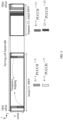
- a RedCap terminal configured with a separate initial UL BWP is used as an example, and for the PRB offset column in Table 1, the following three cases may exist:
- the starting position of the separate initial UL BWP can be referred to as a lower PRB index or a PRB lower index.
- the ending position of the separate initial UL BWP can be referred to as a higher PRB index or a PRB higher index.
- PRB offsets corresponding to the PUCCH resource set indexes in the foregoing (I) are usually very limited, for example, the PRB offsets involved in the first table include only 0, 2, 3, and 4, the requirements of the first initial uplink BWP, such as the separate initial UL BWP, may not be met. Therefore, new higher-layer signaling can be introduced for configuration of the first PRB offset, so as to distinguish the first PRB offset from the PRB offsets corresponding to the PUCCH resource set indexes in the foregoing (I).
- the PRB offset configured through higher-layer signaling in (II) may be denoted as a separate PRB offset.
- the PRB offset configured through higher-layer signaling in (II) may be an offset relative to a starting position of the first initial uplink BWP or an offset relative to an ending position of the first initial uplink BWP.
- the terminal may ignore the PRB offset corresponding to the PUCCH resource set index, for example, ignoring the PRB offsets in the first table; or otherwise, if the network-side device has not configured any PRB offset for the terminal, the terminal uses a PRB offset corresponding to a PUCCH resource set index, for example, using a PRB offset in the first table.
- the RedCap terminal in an example in which a RedCap terminal has configured a separate initial UL BWP, can obtain a starting position and/or an ending position of the separate initial UL BWP and a size N BWP size of the separate initial UL BWP based on configuration information of a system information block (System Information Block, SIB).
- SIB System Information Block
- manners in which the terminal may determine a PRB index of a PUCCH resource for which frequency hopping is disabled include but are not limited to the following three manners.
- X may be equal to ⁇ 8 / N CS ⁇ , and ⁇ ⁇ represents a round up symbol.
- X may be a value configured by the network-side device, such as 1, which is not limited.
- the terminal can determine, based on a second PRB offset, a first PRB index of the PUCCH resource in a first hop and a second PRB index of the PUCCH resource in a second hop.
- the first PRB index is RB BWP offset + ⁇ r PUCCH /N CS ⁇
- the second PRB index is N BWP size ⁇ 1 ⁇ RB BWP offset ⁇ ⁇ r PUCCH /N CS ⁇ .
- the first PRB index is N BWP size ⁇ 1 ⁇ RB BWP offset ⁇ ⁇ r PUCCH ⁇ 8 /N CS ⁇
- the second PRB index is RB BWP offset + ⁇ r PUCCH ⁇ 8 /N CS ⁇
- RB BWP offset represents the second PRB offset
- N BWP size represents a size of the first initial uplink BWP
- r PUCCH represents a PUCCH resource index determined by the terminal, r PUCCH being greater than or equal to 0 and less than or equal to 15; that is, 0 ⁇ r PUCCH ⁇ 15
- N CS represents a total number of initial cyclic shift indexes in a set of initial cyclic shift indexes
- ⁇ ⁇ represents a round down symbol.
- the second PRB offset may be defined as an offset relative to a starting position of the first initial uplink BWP or an offset relative to an ending position of the first initial uplink BWP.
- the second PRB offset being an offset relative to a starting position of the first initial uplink BWP may be configured by the network-side device or may be a default value.
- the second PRB offset being an offset relative to an ending position of the first initial uplink BWP may be configured by the network-side device or may be a default value.
- the second PRB offset may include (I) or (II).
- the PRB offset corresponding to a PUCCH resource set index indicated by the network-side device may be determined using the first table configured through higher-layer signaling.
- a row index in the first table is used to indicate the common PUCCH resource set configured for the terminal.
- the row index in the first table is an index of a PUCCH resource set indicated by the network through PUCCH resource common signaling, such as pucch-ResourceCommon.
- the terminal uses the foregoing common PUCCH resource set configured using the PUCCH resource common signaling.
- the first table can be as shown in Table 1 above.
- a RedCap terminal configured with a separate initial UL BWP is used as an example, and for the PRB offset (offset) column in Table 1, the following three cases may exist:
- the starting position of the separate initial UL BWP can be referred to as a lower PRB index or a PRB lower index.
- the ending position of the separate initial UL BWP can be referred to as a higher PRB index or a PRB higher index.
- PRB offsets corresponding to the PUCCH resource set indexes in the foregoing (I) are usually very limited, for example, the PRB offsets involved in the first table include only 0, 2, 3, and 4, the requirements of the first initial uplink BWP, such as the separate initial UL BWP, may not be met. Therefore, new higher-layer signaling can be introduced for configuration of the second PRB offset, so as to distinguish the second PRB offset from the PRB offsets corresponding to the PUCCH resource set indexes in the foregoing (I).
- the PRB offset configured through higher-layer signaling in (II) may be denoted as a separate PRB offset.
- the PRB offset configured through higher-layer signaling in (II) may be an offset relative to a starting position of the first initial uplink BWP or an offset relative to an ending position of the first initial uplink BWP.
- the separate initial UL BWP is configured near a carrier edge outside an initial UL BWP configured for non-RedCap UE.
- the number of PRBs occupied by a PUCCH for MSG4/MSGB feedback is 1, and in the separate initial UL BWP,
- the separate initial UL BWP is configured near a carrier edge outside an initial UL BWP configured for non-RedCap UE.
- the number of PRBs occupied by a PUCCH for MSG4/MSGB feedback is 1, and in the separate initial UL BWP,
- the separate initial UL BWP is configured near a carrier edge outside an initial UL BWP configured for non-RedCap UE.
- the number of PRBs occupied by a PUCCH for MSG4/MSGB feedback is 1, and in the separate initial UL BWP,
- the separate initial UL BWP is configured near a carrier edge within an initial UL BWP configured for non-RedCap UE.
- the non-RedCap UE in the initial UL BWP,
- the information determining method provided in this embodiment of this application may be performed by an information determining apparatus or a control module for performing the information determining method in the information determining apparatus.
- An information determining apparatus provided in an embodiment of this application is described by assuming that the information determining method in this embodiment of this application is performed by the information determining apparatus.
- FIG. 5 is a schematic structural diagram of an information determining apparatus according to an embodiment of this application.
- the apparatus is applied to a terminal.
- the information determining apparatus 50 includes:
- the first PRB offset includes:
- the first PRB offset is:
- the first PRB offset being an offset relative to a starting position of the first initial uplink BWP is configured by the network-side device; or the first PRB offset being an offset relative to an ending position of the first initial uplink BWP is configured by the network-side device.
- the PRB index of the PUCCH resource is RB BWP offset + ⁇ r PUCCH /N CS ⁇ ; or the PRB index of the PUCCH resource is N BWP size ⁇ 1 ⁇ RB BWP offset ⁇ ⁇ r PUCCH /N CS ⁇ ; where RB BWP offset represents the first PRB offset; N BWP size represents a size of the first initial uplink BWP; r PUCCH represents a PUCCH resource index determined by the terminal, r PUCCH being greater than or equal to 0 and less than or equal to 15; N CS represents a total number of initial cyclic shift indexes in a set of initial cyclic shift indexes; and ⁇ ⁇ represents a round down symbol.
- X is equal to ⁇ 8 /N CS ⁇
- ⁇ ⁇ represents a round up symbol
- X is a value configured by the network-side device.
- the second determining module 52 is further configured to: in a case that frequency hopping is enabled for the PUCCH resource, determine, based on a second PRB offset, a first PRB index of the PUCCH resource in a first hop and a second PRB index of the PUCCH resource in a second hop.
- the first PRB index is RB BWP offset + ⁇ r PUCCH /N CS ⁇
- the second PRB index is N BWP size ⁇ 1 ⁇ RB BWP offset ⁇ ⁇ r PUCCH /N CS ⁇
- the first PRB index is N BWP size ⁇ 1 ⁇ RB BWP offset ⁇ ⁇ r PUCCH ⁇ 8 /N CS ⁇
- the second PRB index is RB BWP offset + ⁇ r PUCCH ⁇ 8 /N CS ⁇
- RB BWP offset represents the second PRB offset
- N BWP size represents a size of the first initial uplink BWP
- r PUCCH represents a PUCCH resource index determined by the terminal, r PUCCH being greater than or equal to 0 and less than or equal to 15
- the second PRB offset includes:
- the second PRB offset is:
- the second PRB offset being an offset relative to a starting position of the first initial uplink BWP is configured by the network-side device; or the second PRB offset being an offset relative to an ending position of the first initial uplink BWP is configured by the network-side device.
- the terminal is a reduced capability RedCap terminal
- the first initial uplink BWP is a separate initial uplink BWP configured for the reduced capability terminal.
- the information determining apparatus 50 in this embodiment of this application may be an apparatus, or an apparatus or electronic device with an operating system, or may be a component, an integrated circuit, or a chip in a terminal.
- the apparatus or electronic device may be a mobile terminal or a non-mobile terminal.
- the mobile terminal may include but is not limited to the foregoing illustrated types of terminals 11.
- the non-mobile terminal may be a server, a network attached storage (Network Attached Storage, NAS), a personal computer (Personal Computer, PC), a television (TeleVision, TV), a teller machine, a self-service machine, or the like. This is not specifically limited in this embodiment of this application.
- the information determining apparatus 50 provided in this embodiment of this application can implement the processes implemented by the method embodiment in FIG. 2 , with the same technical effects achieved. To avoid repetition, details are not repeated herein.
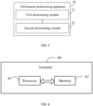
- an embodiment of this application further provides a terminal 60, including a processor 61, a memory 62, and a program or instructions stored in the memory 62 and capable of running on the processor 61.
- a terminal 60 including a processor 61, a memory 62, and a program or instructions stored in the memory 62 and capable of running on the processor 61.
- the program or instructions are executed by the processor 61, each process of the foregoing information determining method embodiment is implemented, with the same technical effect achieved. To avoid repetition, details are not described herein again.
- An embodiment of this application further provides a terminal, including a processor and a communications interface, where the processor is configured to determine a PUCCH resource configured for the terminal on a first initial uplink BWP and determine a PRB index of the PUCCH resource based on a first PRB offset in a case that frequency hopping of the PUCCH resource is disabled.
- the terminal embodiment can implement the processes in foregoing embodiment of the information determining method, with the same technical effects achieved. To avoid repetition, details are not repeated herein.
- FIG. 7 is a schematic diagram of a hardware structure of a terminal implementing embodiments of this application.
- the terminal 700 includes but is not limited to at least some of the components such as a radio frequency unit 701, a network module 702, an audio output unit 703, an input unit 704, a sensor 705, a display unit 706, a user input unit 707, an interface unit 708, a memory 709, and a processor 710.
- the terminal 700 may further include a power supply (for example, a battery) that supplies power to various components.
- the power supply may be logically connected to the processor 710 through a power management system, so that functions such as charge and discharge management and power consumption management are implemented by using the power management system.
- the terminal is not limited to the terminal structure shown in FIG. 7 .
- the terminal may include more or fewer components than shown in the figure, or combine some of the components, or arrange the components differently. Details are not described herein.
- the input unit 704 may include a graphics processing unit (Graphics Processing Unit, GPU) 7041 and a microphone 7042.
- the graphics processing unit 7041 processes image data of a static picture or a video that is obtained by an image capture apparatus (for example, a camera) in a video capture mode or an image capture mode.
- the display unit 706 may include the display panel 7061.
- the display panel 7061 may be configured in a form of a liquid crystal display, an organic light-emitting diode, or the like.
- the user input unit 707 includes a touch panel 7071 and other input devices 7072.
- the touch panel 7071 is also referred to as a touchscreen.
- the touch panel 7071 may include two parts: a touch detection apparatus and a touch controller.
- the other input devices 7072 may include but are not limited to a physical keyboard, a function button (for example, a volume control button or a power button), a trackball, a mouse, and a joystick. Details are not described herein.
- the radio frequency unit 701 sends downlink data received from a network-side device to the processor 710 for processing, and in addition, sends uplink data to the network-side device.
- the radio frequency unit 701 includes but is not limited to an antenna, at least one amplifier, a transceiver, a coupler, a low noise amplifier, and a duplexer.
- the memory 709 may be configured to store software programs or instructions and various data.
- the memory 709 may mainly include a program or instructions storage area and a data storage area.
- the program or instructions storage area may store an operating system, an application program or instructions required by at least one function (for example, an audio play function or an image play function), and the like.
- the memory 709 may include a high-speed random access memory, and may further include a non-volatile memory, where the non-volatile memory may be a read-only memory (Read-Only Memory, ROM), a programmable read-only memory (Programmable ROM, PROM), an erasable programmable read-only memory (Erasable PROM, EPROM), an electrically erasable programmable read-only memory (Electrically EPROM, EEPROM), or a flash memory, for example, at least one disk storage device, flash memory device, or other volatile solid-state storage device.
- ROM Read-Only Memory
- PROM programmable read-only memory
- Erasable PROM Erasable PROM
- EPROM electrically erasable programmable read-only memory
- EEPROM electrically erasable programmable read-only memory
- flash memory for example, at least one disk storage device, flash memory device, or other volatile solid-state storage device.
- the processor 710 may include one or more processing units.
- an application processor and a modem processor may be integrated in the processor 710.
- the application processor primarily processes an operating system, user interfaces, application programs or instructions, and the like.
- the modem processor primarily processes radio communication, for example, being a baseband processor. It can be understood that the modem processor may alternatively be not integrated in the processor 710.
- the processor 710 is configured to determine a PUCCH resource configured for the terminal on a first initial uplink BWP and determine a PRB index of the PUCCH resource based on a first PRB offset in a case that frequency hopping of the PUCCH resource is disabled.
- the first PRB offset includes:
- the first PRB offset is:
- the first PRB offset being an offset relative to a starting position of the first initial uplink BWP is configured by the network-side device; or the first PRB offset being an offset relative to an ending position of the first initial uplink BWP is configured by the network-side device.
- the PRB index of the PUCCH resource is RB BWP offset + ⁇ r PUCCH / N CS ⁇ ; or the PRB index of the PUCCH resource is N BWP size ⁇ 1 ⁇ RB BWP offset ⁇ ⁇ r PUCCH / N CS ⁇ ; where RB BWP offset represents the first PRB offset; N BWP size represents a size of the first initial uplink BWP; r PUCCH represents a PUCCH resource index determined by the terminal, r PUCCH being greater than or equal to 0 and less than or equal to 15; N CS represents a total number of initial cyclic shift indexes in a set of initial cyclic shift indexes; and ⁇ ⁇ represents a round down symbol.
- X is equal to ⁇ 8 / N CS ⁇
- ⁇ ⁇ represents a round up symbol
- X is a value configured by the network-side device.
- the processor 710 is further configured to: in a case that frequency hopping is enabled for the PUCCH resource, determine, based on a second PRB offset, a first PRB index of the PUCCH resource in a first hop and a second PRB index of the PUCCH resource in a second hop.
- the first PRB index is RB BWP offset + ⁇ r PUCCH / N CS ⁇
- the second PRB index is N BWP size ⁇ 1 ⁇ RB BWP offset ⁇ ⁇ r PUCCH / N CS ⁇
- the first PRB index is N BWP size ⁇ 1 ⁇ RB BWP offset ⁇ ⁇ r PUCCH ⁇ 8 /N CS ⁇
- the second PRB index is RB BWP offset + ⁇ r PUCCH ⁇ 8 /N CS ⁇
- RB BWP offset represents the second PRB offset
- N BWP size represents a size of the first initial uplink BWP
- r PUCCH represents a PUCCH resource index determined by the terminal, r PUCCH being greater than or equal to 0 and less than or equal to 15;
- N BWP offset represents the second PRB offset
- N BWP size represents a size of the first initial uplink BWP
- the second PRB offset includes:
- the second PRB offset is:
- the second PRB offset being an offset relative to a starting position of the first initial uplink BWP is configured by the network-side device; or the second PRB offset being an offset relative to an ending position of the first initial uplink BWP is configured by the network-side device.
- the terminal 700 is a reduced capability RedCap terminal
- the first initial uplink BWP is a separate initial uplink BWP configured for the reduced capability terminal.
- the terminal 700 provided in this embodiment of this application is capable of implementing the processes implemented in the method embodiment shown in FIG. 2 , with the same technical effects achieved. To avoid repetition, details are not repeated herein.
- An embodiment of this application further provides a readable storage medium, where the readable storage medium has stored a program or instructions thereon, and when the program or instructions are executed by a processor, the processes of the foregoing embodiments of the information determining method are implemented, with the same technical effects achieved. To avoid repetition, details are not repeated herein.
- the processor is a processor in the terminal in the foregoing embodiment.
- the readable storage medium includes a computer-readable storage medium such as a computer read-only memory (Read-Only Memory, ROM), a random access memory (Random Access Memory, RAM), a magnetic disk, an optical disc, or the like.
- Another embodiment of this application provides a chip, where the chip includes a processor and a communications interface, the communications interface is coupled to the processor, and the processor is configured to run a program or instructions to implement the processes of the foregoing embodiments of the information determining method, with the same technical effects achieved. To avoid repetition, details are not repeated herein.
- the chip mentioned in an embodiment of this application may also be referred to as a system-level chip, a system chip, a chip system, a system-on-chip, or the like.
- An embodiment of this application further provides a computer program product, where the computer program product is stored in a non-transitory storage medium.
- the computer program product is executed by at least one processor, the processes of the foregoing embodiments of the information determining method are implemented, with the same technical effects achieved. To avoid repetition, details are not repeated herein.
- An embodiment of this application further provides a communications device configured to execute the processes of the foregoing embodiments of the information determining method, with the same technical effects achieved. To avoid repetition, details are not repeated herein.
- the methods in the foregoing embodiments can be implemented through software on a necessary general hardware platform or certainly through hardware only, but in many cases, the former is the more preferred implementation.
- the technical solutions of this application essentially or the part contributing to the prior art may be implemented in a form of a software product.
- the software product is stored in a storage medium (such as a ROM/RAM, a magnetic disk, or an optical disc), and includes several instructions for instructing a terminal (which may be a mobile phone, a computer, a server, an air conditioner, a network-side device, or the like) to perform the methods described in the embodiments of this application.
Landscapes
- Engineering & Computer Science (AREA)
- Signal Processing (AREA)
- Computer Networks & Wireless Communication (AREA)
- Mobile Radio Communication Systems (AREA)
Applications Claiming Priority (2)
| Application Number | Priority Date | Filing Date | Title |
|---|---|---|---|
| CN202111306433.6A CN116094671B (zh) | 2021-11-05 | 2021-11-05 | 信息确定方法、装置、终端及可读存储介质 |
| PCT/CN2022/129472 WO2023078330A1 (zh) | 2021-11-05 | 2022-11-03 | 信息确定方法、装置、终端及可读存储介质 |
Publications (2)
| Publication Number | Publication Date |
|---|---|
| EP4429152A1 true EP4429152A1 (de) | 2024-09-11 |
| EP4429152A4 EP4429152A4 (de) | 2025-03-19 |
Family
ID=86185485
Family Applications (1)
| Application Number | Title | Priority Date | Filing Date |
|---|---|---|---|
| EP22889352.5A Pending EP4429152A4 (de) | 2021-11-05 | 2022-11-03 | Informationsbestimmungsverfahren und -vorrichtung, endgerät und lesbares speichermedium |
Country Status (4)
| Country | Link |
|---|---|
| US (1) | US20240284464A1 (de) |
| EP (1) | EP4429152A4 (de) |
| CN (1) | CN116094671B (de) |
| WO (1) | WO2023078330A1 (de) |
Family Cites Families (6)
| Publication number | Priority date | Publication date | Assignee | Title |
|---|---|---|---|---|
| CN108809557A (zh) * | 2017-04-28 | 2018-11-13 | 华为技术有限公司 | 传输信息的方法和装置 |
| CN110324896B (zh) * | 2018-03-28 | 2021-10-22 | 大唐移动通信设备有限公司 | 资源指示、确定方法及装置 |
| WO2020146643A1 (en) * | 2019-01-10 | 2020-07-16 | Apple Inc. | Resource allocation for physical uplink control channel during initial access in nr-unlicensed |
| CN114175550B (zh) * | 2019-06-06 | 2025-04-29 | 苹果公司 | 两步随机接入信道过程中对消息b的响应 |
| CN114342530A (zh) * | 2019-07-03 | 2022-04-12 | 瑞典爱立信有限公司 | 针对交错传输的频域资源分配 |
| US11743887B2 (en) * | 2019-10-15 | 2023-08-29 | Intel Corporation | Resource allocation for physical uplink control channel during initial access in new radio unlicensed |
-
2021
- 2021-11-05 CN CN202111306433.6A patent/CN116094671B/zh active Active
-
2022
- 2022-11-03 EP EP22889352.5A patent/EP4429152A4/de active Pending
- 2022-11-03 WO PCT/CN2022/129472 patent/WO2023078330A1/zh not_active Ceased
-
2024
- 2024-05-02 US US18/653,686 patent/US20240284464A1/en active Pending
Also Published As
| Publication number | Publication date |
|---|---|
| WO2023078330A1 (zh) | 2023-05-11 |
| CN116094671B (zh) | 2025-07-18 |
| US20240284464A1 (en) | 2024-08-22 |
| EP4429152A4 (de) | 2025-03-19 |
| CN116094671A (zh) | 2023-05-09 |
Similar Documents
| Publication | Publication Date | Title |
|---|---|---|
| CN116112131B (zh) | Prach重复传输方法、终端及网络侧设备 | |
| EP4518552A1 (de) | Verfahren und vorrichtung zur bestimmung der übertragungsressource eines physikalischen direktzugriffskanals, endgerät und vorrichtung | |
| US20240008038A1 (en) | Harq ack feedback method and apparatus, terminal, and storage medium | |
| US20250261179A1 (en) | Communication method and apparatus, and terminal | |
| EP4462713A1 (de) | Portabbildungsverfahren für klangreferenzsignal und endgerät | |
| US20240324004A1 (en) | Information transport method and device | |
| US20240283589A1 (en) | Available slot determining method and apparatus, and terminal | |
| EP4319397A1 (de) | Verfahren und vorrichtung zur bestimmung der übertragungsrichtung, endgerät und netzwerkseitige vorrichtung | |
| EP4460108A1 (de) | Kommunikationsbetriebsausführungsverfahren, vorrichtung, endgerät und speichermedium | |
| EP4422291A1 (de) | Informationsmeldeverfahren, informationsempfangsverfahren und endgerät, netzwerkseitige vorrichtung und speichermedium | |
| EP4307803B1 (de) | Direktzugriffsverfahren und -vorrichtung, endgerät und speichermedium | |
| US20240214129A1 (en) | Method for Determining HARQ-ACK Transmission Resource, Terminal, and Storage Medium | |
| EP4429152A1 (de) | Informationsbestimmungsverfahren und -vorrichtung, endgerät und lesbares speichermedium | |
| EP4615049A1 (de) | Verfahren zur wiederholten übertragung eines gemeinsamen pucch, endgerät und netzwerkseitige vorrichtung | |
| US20230421293A1 (en) | Transmission processing method and apparatus and terminal | |
| EP4661536A1 (de) | Bwp-bestimmungsverfahren, übertragungsverfahren, vorrichtung, endgerät und netzwerkseitige vorrichtung | |
| US20230422253A1 (en) | Physical uplink control channel resource determining method, terminal, and network-side device | |
| US12543175B2 (en) | Resource transmission method, resource transmission apparatus, and communications device | |
| EP4503672A1 (de) | Ressourcenbestimmungsverfahren und -vorrichtung, endgerät und speichermedium | |
| CN116032442B (zh) | 波束应用时间确定方法、装置及通信设备 | |
| CN115776727B (zh) | 时隙配置方法、终端及网络侧设备 | |
| KR20250002726A (ko) | 하이브리드 자동 재송 요구-확인응답(harq-ack) 코드북을 결정하기 위한 방법, 장치 및 단말 | |
| CN114641013B (zh) | 信息传输方法、装置、终端及网络侧设备 | |
| EP4301068A1 (de) | Verfahren und vorrichtung zur anzeige von scs eines anfänglichen downlink-bwp | |
| EP4383889A1 (de) | Verfahren zur bestimmung der strahlanwendungszeit sowie endgerät und netzwerkseitige vorrichtung |
Legal Events
| Date | Code | Title | Description |
|---|---|---|---|
| STAA | Information on the status of an ep patent application or granted ep patent |
Free format text: STATUS: THE INTERNATIONAL PUBLICATION HAS BEEN MADE |
|
| PUAI | Public reference made under article 153(3) epc to a published international application that has entered the european phase |
Free format text: ORIGINAL CODE: 0009012 |
|
| STAA | Information on the status of an ep patent application or granted ep patent |
Free format text: STATUS: REQUEST FOR EXAMINATION WAS MADE |
|
| 17P | Request for examination filed |
Effective date: 20240531 |
|
| AK | Designated contracting states |
Kind code of ref document: A1 Designated state(s): AL AT BE BG CH CY CZ DE DK EE ES FI FR GB GR HR HU IE IS IT LI LT LU LV MC ME MK MT NL NO PL PT RO RS SE SI SK SM TR |
|
| DAV | Request for validation of the european patent (deleted) | ||
| DAX | Request for extension of the european patent (deleted) | ||
| A4 | Supplementary search report drawn up and despatched |
Effective date: 20250214 |
|
| RIC1 | Information provided on ipc code assigned before grant |
Ipc: H04B 1/7143 20110101ALI20250211BHEP Ipc: H04W 72/0453 20230101ALI20250211BHEP Ipc: H04W 72/51 20230101ALI20250211BHEP Ipc: H04W 72/21 20230101ALI20250211BHEP Ipc: H04B 1/713 20110101ALI20250211BHEP Ipc: H04W 72/04 20230101ALI20250211BHEP Ipc: H04L 5/00 20060101AFI20250211BHEP |