EP4429038A1 - Modular sequential mating electrical connector system - Google Patents
Modular sequential mating electrical connector system Download PDFInfo
- Publication number
- EP4429038A1 EP4429038A1 EP24161996.4A EP24161996A EP4429038A1 EP 4429038 A1 EP4429038 A1 EP 4429038A1 EP 24161996 A EP24161996 A EP 24161996A EP 4429038 A1 EP4429038 A1 EP 4429038A1
- Authority
- EP
- European Patent Office
- Prior art keywords
- module
- interface
- terminal
- terminal module
- header
- Prior art date
- Legal status (The legal status is an assumption and is not a legal conclusion. Google has not performed a legal analysis and makes no representation as to the accuracy of the status listed.)
- Pending
Links
Images




Classifications
-
- H—ELECTRICITY
- H01—ELECTRIC ELEMENTS
- H01R—ELECTRICALLY-CONDUCTIVE CONNECTIONS; STRUCTURAL ASSOCIATIONS OF A PLURALITY OF MUTUALLY-INSULATED ELECTRICAL CONNECTING ELEMENTS; COUPLING DEVICES; CURRENT COLLECTORS
- H01R13/00—Details of coupling devices of the kinds covered by groups H01R12/70 or H01R24/00 - H01R33/00
- H01R13/46—Bases; Cases
- H01R13/516—Means for holding or embracing insulating body, e.g. casing, hoods
- H01R13/518—Means for holding or embracing insulating body, e.g. casing, hoods for holding or embracing several coupling parts, e.g. frames
-
- H—ELECTRICITY
- H01—ELECTRIC ELEMENTS
- H01R—ELECTRICALLY-CONDUCTIVE CONNECTIONS; STRUCTURAL ASSOCIATIONS OF A PLURALITY OF MUTUALLY-INSULATED ELECTRICAL CONNECTING ELEMENTS; COUPLING DEVICES; CURRENT COLLECTORS
- H01R13/00—Details of coupling devices of the kinds covered by groups H01R12/70 or H01R24/00 - H01R33/00
- H01R13/46—Bases; Cases
- H01R13/514—Bases; Cases composed as a modular blocks or assembly, i.e. composed of co-operating parts provided with contact members or holding contact members between them
-
- H—ELECTRICITY
- H01—ELECTRIC ELEMENTS
- H01R—ELECTRICALLY-CONDUCTIVE CONNECTIONS; STRUCTURAL ASSOCIATIONS OF A PLURALITY OF MUTUALLY-INSULATED ELECTRICAL CONNECTING ELEMENTS; COUPLING DEVICES; CURRENT COLLECTORS
- H01R13/00—Details of coupling devices of the kinds covered by groups H01R12/70 or H01R24/00 - H01R33/00
- H01R13/62—Means for facilitating engagement or disengagement of coupling parts or for holding them in engagement
- H01R13/629—Additional means for facilitating engagement or disengagement of coupling parts, e.g. aligning or guiding means, levers, gas pressure electrical locking indicators, manufacturing tolerances
-
- H—ELECTRICITY
- H01—ELECTRIC ELEMENTS
- H01R—ELECTRICALLY-CONDUCTIVE CONNECTIONS; STRUCTURAL ASSOCIATIONS OF A PLURALITY OF MUTUALLY-INSULATED ELECTRICAL CONNECTING ELEMENTS; COUPLING DEVICES; CURRENT COLLECTORS
- H01R43/00—Apparatus or processes specially adapted for manufacturing, assembling, maintaining, or repairing of line connectors or current collectors or for joining electric conductors
- H01R43/20—Apparatus or processes specially adapted for manufacturing, assembling, maintaining, or repairing of line connectors or current collectors or for joining electric conductors for assembling or disassembling contact members with insulating base, case or sleeve
Definitions
- the invention generally relates to electrical connectors, and more particularly electrical connectors for coupling multiple high speed data terminals.
- a vehicle electrical system may include one or more wiring harnesses that carry cables terminated by terminals used for connection to components of a vehicle electrical system.
- Recent vehicles incorporate more and more complex electrical systems that require data to be transferred at higher speeds than traditional automotive cabling, examples of which include coaxial, twisted pair wire, and other high-speed data cables.
- An electrical connector is described that provides for the coupling of multiple high-speed data cables simultaneously that is relatively easy and inexpensive to manufacture and connect as part of a vehicle assembly process.
- the described connector may further be particularly resilient to intended disconnection in comparison to other connectors.
- an electrical connection system includes a module interface, a first terminal module configured to be retained in the module interface, and a second terminal module configured to be retained adjacent to the first terminal module in the module interface, locked in a predefined position staggered relative to the first terminal module.
- the module interface is configured to be seated on a header interface, and moved relative to the header interface until the first terminal module is mated.
- the module interface is further configured to be released once the first terminal module is mated to the header interface and moved to a fully seated position on the header interface, which mates the second terminal module and locks the module interface to the header interface.
- a method in other aspects, includes retaining a first terminal module in a module interface.
- the method further includes retaining a second terminal module in the module interface locked in a predefined position in the module interface staggered relative to the first terminal module.
- the method further includes seating the module interface on a corresponding header interface.
- the method further includes moving the module interface relative to the header interface until the first terminal module is mated.
- the method further includes mating the first terminal module, thereby releasing the module interface to move relative to the header interface.
- the method further includes moving the module interface to a fully seated position on the header interface, which mates the second terminal module and engages a lock to secure the module interface to the header interface.
- a module interface includes a first module channel configured to retain a first terminal module in the first terminal channel, and a second module channel configured to retain a second terminal module in the second terminal channel, locked in a predefined position longitudinally staggered relative to the first terminal module in the module interface.
- the module interface is configured to be arranged on a header interface, and moved relative to the header interface until the first terminal module is mated.
- the module interface is configured to be released once the first terminal module is mated to the header interface and moved to a fully seated position on the header interface, which mates the second terminal module and locks the module interface to the header interface.
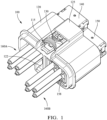
- FIG. 1 is a perspective view showing one example of an electrical connection system 100 according to some embodiments.
- the connection system 100 has been assembled in preparation for mating with a corresponding header interface 110 (as shown in FIG. 5A and described in further detail below).
- FIG. 2A is an exploded view showing components of the connection system 100 according to some embodiments.
- FIG. 2B is an exploded view showing an opposite side of the connection system 100 components depicted in FIG. 2A according to some embodiments.
- the connection system 100 includes a module interface 120, a first terminal module 140, and a second terminal module 150.
- the first and second terminal modules 140, 150 are each configured to carry terminals (not shown) that terminate a plurality of cables 160A, 160B, which may be high-speed data terminals such as coaxial, twisted-pair, or other types of high-speed data terminals.
- terminal module 140 carries four terminals (not shown) that terminate four cables 160A
- terminal module 150 also carries terminals that terminate four cables 160B.
- one or more of terminal module 140, 150 may carry a different number of terminals that terminate a different number of cables for mating. As shown in FIGS.
- the first terminal module 140 includes a plurality of terminal stablilizer features 148 that support terminals (not shown) and/or cables 160A
- the second terminal module 150 includes a plurality of terminal support features 158 that support terminals (not shown) and and/or cables 160B.
- the module interface 120 is configured to retain the first terminal module 140 and the second terminal module 150 to facilitate mating and locking the first and second terminal modules 140, 150 to a corresponding interface, such as header interface 110.
- the module interface 120 is configured to retain the first terminal module 140 differently than the second terminal module 150 is retained for mating.
- the module interface 120 is configured to support the respective terminal modules 140, 150 staggered in the module interface 120, such that the terminal modules 140, 150 are mated in sequence, by first mating the first terminal module 140, and then mating the second terminal module 150, when the module interface 120 is seated on a header interface 110 and moved to a fully seated position on the header interface 110.
- traditional electrical connection systems configured to connect a large number of terminals may require a significant insertion force to be mated, which may be more than a force recommended for a human or machine operator.
- such traditional electrical connectors may include an additional mate assist feature, such as a lever or other geared feature configured to a lower an exertion force needed for mating the terminals.
- connection system 100 may be useful to mate a large number of terminals at one time, but without requiring a mate assist features as described above. For example, by arranging the terminal modules 140, 150 to be sequentially mated, the insertion force required to connect the terminals can be distributed across the respective terminal modules, which may in some examples cut in half the insertion force needed to mate the connection system 100. In some examples, connection system 100 may be relatively easy and/or inexpensive to manufacture in comparison with traditional connection systems that employ a mate assist feature as described above.
- connection system 100 is depicted that includes two terminal modules 140, 150, that are secured differently from one another in the module interface 120, and staggered relative to one another to support sequential mating.
- connection system 100 may carry more terminal modules than shown that are configured as either a first terminal module 140, or a second terminal module 150.
- a connection system 100 may include a second terminal module 150, and a pair of first terminal modules 140 staggered relative to the second terminal module 150 to support sequential mating of all three terminal modules.
- a connection system 100 may alternate between second terminal modules 150 and first terminal modules 140, staggered relative to another, in rows.
- the connection system 100 may include any combination of first and second terminal modules 140, 150 arranged in two, three or more rows, with each row staggered relative to other rows to distribute an insertion force required to mate the connection system 100 across multiple terminal modules.
- distributing the insertion force across multiple terminal modules 140, 150 as described may enable terminal modules 140, 150 that carry more terminals than shown for mating.
- terminal module 140, 150 may support more than the four terminals shown, for example, 8, 16, or even 32 terminals may be carried by each terminal module 140, 150 to be mated.
- FIG. 3A is a perspective view showing a module interface 120 according to some embodiments.
- FIG. 3B is a perspective view showing an opposite side of the module interface 120 depicted in FIG. 3A according to some embodiments.
- the module interface 120 includes module channels 124A and 124B.
- Module channel 124A is configured to retain terminal module 140
- module channel 124B is configured to retain terminal module 150 adjacent to terminal module 140.
- Module channel 124A and the first terminal module 140 each include features configured to engage such that the first terminal module 140 is retained in the module interface 120.
- the first terminal module 140 includes a mating feature 142 configured to engage with a corresponding mating channel 121 defined in the module channel 124A.
- the first terminal module 140 may also include an optional seal 144.
- the module interface 120 and the second terminal module 150 are configured such that the second terminal module 150 is retained in the module interface 120 locked in a predefined position in the module interface 120.
- the second terminal module 150 includes a pair of lock features 156A, 156B on opposed sides of the second terminal module 150 that are configured to engage with corresponding lock features 126A, 126B, respectively, on opposed sides of the module channel 124B to retain the second terminal module 150 locked in a predefined position in the module channel 124B.
- the second terminal module 150 may be described as locked in a predefined position, fixed relative to a longitudinal axis through the module channel 124B of the module interface 120, which corresponds to an insertion direction 102 in which second terminal module 150 is inserted into the module channel 124B.
- the second terminal module 150 may also include an optional seal 154.
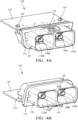
- FIG. 4A is a perspective view showing a header interface of an electrical connection system according to some embodiments.
- FIG. 4B is a perspective view showing an opposite side of the header interface depicted in FIG. 4A according to some embodiments. As shown in FIGS.
- the header interface 110 is configured to facilitate electrical connections to one or more components (not shown), mounted on a printed circuit board (PCB) 112.
- the header interface 110 is coupled to the PCB 112 by a pair of bolts 119 and includes a pair of openings 114A, 114B surrounded by a collar 116.
- the openings 114A, 114B correspond to the terminal modules 140, 150 and carry corresponding terminals 170A, 170B respectively, for mating with terminals (not shown) carried by the terminal modules 140, 150.
- each of the openings 114A, 114B in the depicted example facilitate access to four terminals, which correspond to the four terminals carried by each of the terminal modules 140, 150.
- the terminals carried by header interface 110 are coupled by vertical conductors 113 to the PCB 112 (e.g., to traces or other conductive structures on or in the PCB 112, not shown).
- the collar 116 extends from a ledge 117 and is configured for module interface 120 to be seated on the collar 116 for mating.
- the collar includes a lock feature 115 that corresponds to lock feature 125 of the module interface on a first outer surface, and a raised protrusion 118 with an angled surface 118A on a second outer surface.
- the second terminal module 150 is inserted in module channel 124B, and moved longitudinally forward (in insertion direction 102) until lock features 156A and 156B engage corresponding lock features 126A, 126B in the module channel 124B to lock the second terminal module 150 in the predefined position.
- the first terminal module 140 is inserted into the module channel 124A of the module interface 120, and moved longitudinally forward (in insertion direction 102) into the module channel 124A, with engagement end 123 of elongate spring 122 engaged with mating feature 142 (e.g., with engagement end 123 of elongate spring 122 between rails 145, on raised portion 146).
- the first terminal module 140 may be moved longitudinally forward, in the insertion direction 102, until the engagement end 123 reaches the recessed portion 143 and snaps into the recessed portion 143, which movably secures the first terminal module 140 in the module channel 124 (i.e., with limited travel of the engagement end 123 in the recessed portion 143).
- the module interface 120 may be seated on the header interface 110, for example on a collar 116 of the header interface 110, and moved relative to (e.g., towards) the header interface 110 to first mate the first terminal module 140, and then mate the second terminal module 150.
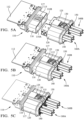
- FIGS. 5A-5C show the module interface 120 being coupled to a header interface 110 according to some embodiments.
- FIG. 5A is a perspective view showing module interface 120 assembled as shown in FIG. 1 and prepared to be seated on a header interface 110 according to some embodiments.
- the first terminal module 140 is movably secured, with limited travel in the insertion direction 102, in the module interface 120 (e.g., in module channel 124A), for example with engagement end 123 of module channel 124A engaged with the recessed portion 143 of mating channel 121.
- the second terminal module 150 is retained in the module interface 120 adjacent to the first terminal module 140 (e.g., in module channel 124B), locked (via lock features 156A, 156B engaged with lock features 126A, 126B) in a predefined position staggered (i.e., longitudinally, in the insertion direction 102) relative to the first terminal module 140.
- FIG. 5B is a perspective view showing an electrical connection system 100 with a module interface 120 seated on header interface 110 (e.g., on collar 116), according to some embodiments.
- the module interface 120 may be moved relative to (e.g., longitudinally, in the insertion direction 102) the header interface 110 to a pre-seated position to mate the first terminal module 140, which releases the module interface 120 to move further relative to (e.g., towards) on the header interface 110 to a fully seated position, which mates the second terminal module 150, and locks the module interface 120 to the header interface 110 according to some embodiments.
- FIG. 5B is a perspective view showing an electrical connection system 100 with a module interface 120 seated on header interface 110 (e.g., on collar 116), according to some embodiments.
- the module interface 120 may be moved relative to (e.g., longitudinally, in the insertion direction 102) the header interface 110 to a pre-seated position to mate the first terminal module 140, which releases the module interface 120 to move further relative to (
- protrusion surface 118A in the pre-staged position, protrusion surface 118A, which is angled, engages with surface 123A of engagement end 123.
- protrusion 118 pushes elongate spring 122 downward and under stop 123, which releases module interface 120 to moved further relative to (e.g., towards) to the fully seated position shown in FIGS. 5C and 6B .
- FIG. 5C is a perspective view showing an electrical connection system 100 with a module interface 120 in a fully seated position seated header interface 110 (e.g., on collar 116), according to some embodiments.
- FIG. 6A is a cross section view showing one example of a connection system 100 with a module interface 120 in a pre-seated position on a header interface 110 as shown in FIG. 5C , in some embodiments.
- FIG. 6B is a cross section view showing the module interface 120 of FIG. 6A in a fully seated position on a header interface 110 as shown in FIG. 5C , in some embodiments.
- module interface 120 may be moved relative to (e.g., towards) on the header interface 110 until protrusion 118 engages with stop 147 of mating feature 142, with angled surface 118A engaged with ramp 147A, which guides protrusion 118 to the position shown in FIG. 6A , with protrusion 118 arranged between the stop 147 and the seal 144, with the angled surface 118A of the protrusion 118 against a first ramp 123A of the engagement end 123 in the pre-seated position. Moving the module interface 120 to the pre-seated position shown in FIG.
- the first terminal module 140 mates terminals carried by the first terminal module 140 with corresponding terminals 170A of the header unit opening 114A.
- the module interface 120 is released (e.g., by protrusion 118 engaging engagement end 123 to move downward) to move further relative to (e.g., towards), with angled surface 118A engaged with ramp 123A on engagement end 123, which pushes the engagement end underneath the stop 147 and finally past the stop 147, with ramp 123B of the engagement end 123 engaged with angled surface 118B of protrusion 118B, as shown in FIG. 6B .
- the protrusion 118 is wedged into a void 180 between the engagement end 123, the stop 147, and the first terminal module 140, for example as shown engaging the optional seal 144.
- the engagement end 123 and the protrusion 118 are engaged, securing the first terminal module 140 to the module interface 120.
- a distance that the protrusion travels into the void 180 from the pre-seated position shown in FIG. 6A to the fully seated position shown in FIG. 6B corresponds to a longitudinal distance (in the insertion direction 102) that the first terminal module 140 and the second terminal module 150 were staggered relative to one another in the module interface 120, when assembled prior to mating as shown in the FIG. 1 example.
- Moving the module interface 120 to the fully seated position shown in FIG. 6 mates the second terminal module 150 (e.g., mates terminals carried by the second terminal module 150 with corresponding terminals 170B of the header unit opening 114B), and secures the first terminal module 140 in position in the module interface 120.
- Moving the module interface 120 to the fully seated position shown further causes lock features 115 and 125 to engage, thereby locking the first terminal module 140, the second terminal module 150, and the module interface 120 to the header interface 110 as shown in the example of FIG. 5C .
- FIG. 6 mates the second terminal module 150 (e.g., mates terminals carried by the second terminal module 150 with corresponding terminals 170B of the header unit opening 114B), and secures the first terminal module 140 in position in the module interface 120.
- Moving the module interface 120 to the fully seated position shown further causes lock features 115 and 125 to engage, thereby locking the first terminal module 140, the second terminal module 150, and the module interface 120 to the header interface 110 as shown in the example
- CPA 130 may be applied to the lock features 115, 125, which prevent the lock features 115, 125 from disengaging unless the CPA 130 is removed by an operator.
- connection system 100 may beneficially support the coupling of many terminals using a single connector, without the use of a mating assist feature, such as a lever lock, to reduce a mating force needed to mate the connection system.
- a mating assist feature such as a lever lock
- FIG. 7 is a flow diagram that depicts a method 700 of assembling an electrical connection system according to some embodiments.
- the method includes retaining a first terminal module (e.g., 140) in a module interface (e.g., 120).
- the method includes retaining a second terminal module (e.g., 150) locked in the module interface, for example locked in a predefined position in the module interface staggered relative to the first terminal module.
- the first terminal module and the second terminal module each carry a plurality of pairs of high-speed data terminals.
- the method includes retaining the second terminal module 150 arranged longitudinally relative to (e.g., towards) (e.g., in an insertion direction 102 as shown in FIGS. 2A and 2B ) of the first terminal module 140 in the module interface 120 before seating the module interface 120 on the header interface 110.
- the method further comprises engaging a mating feature (e.g., 142) of the first terminal module that engages with a mating channel (e.g., 121) defined in the module interface 120 to secure the first terminal module 140 in the module interface 120.
- the mating feature includes a raised portion (e.g., 146), a recessed portion (e.g., 143), and a stop (e.g., 147).
- the mating channel 121 includes an elongate spring (e.g., 122) with an engagement end (e.g., 123).
- the method further includes seating the module interface on a header interface (e.g., 110).
- the method further includes mating the first terminal module, for example, by moving the module interface further onto the header interface to a pre-seated position on the header interface (e.g., as shown in FIGS. 5B and 6A ).
- the method further includes, moving the module interface to a fully seated position on the header interface (e.g., as shown in FIGS. C and 6B), which mates the second terminal module and engages a lock to secure the module interface to the header interface.
- moving the module interface to a fully seated position on the header interface may cause a lock feature (e.g., 125) of the module interface to engage with a corresponding lock feature (e.g., 115) of the header interface to lock the module interface to the header interface.
- the method further includes applying a connector position assurance (CPA) feature (e.g., 130) that engages with the first lock feature and the second lock feature to prevent the first and second lock features from disengaging.
- CCA connector position assurance
Landscapes
- Engineering & Computer Science (AREA)
- Manufacturing & Machinery (AREA)
- Details Of Connecting Devices For Male And Female Coupling (AREA)
Abstract
An electrical connection system is described that includes a module interface, a first terminal module, and a second terminal module. The first terminal module is configured to be retained in the module interface. The second terminal module is configured to be retained adjacent to the first terminal module in the module interface, secured in a predefined position staggered relative to the first terminal module. The module interface is configured to be seated on a header interface and moved relative to the header interface until the first terminal module is mated. The module interface is configured to be released once the first terminal module is mated and moved to a fully seated position on the header interface, which mates the second terminal module and locks the module interface to the header interface.
Description
- This application is a non-provisional application that claims priority to provisional application
63/450,463 titled "MODULAR SEQUENTIAL MATING ELECTRICAL CONNECTOR SYSTEM," filed March 7, 2023 - The invention generally relates to electrical connectors, and more particularly electrical connectors for coupling multiple high speed data terminals.
- Electrical connectors are commonly used in automotive vehicle systems to couple electrical components and systems to one another. For example, a vehicle electrical system may include one or more wiring harnesses that carry cables terminated by terminals used for connection to components of a vehicle electrical system.
- Recent vehicles incorporate more and more complex electrical systems that require data to be transferred at higher speeds than traditional automotive cabling, examples of which include coaxial, twisted pair wire, and other high-speed data cables.
- In some examples, it may be desirable to couple many high-speed data cables together simultaneously, in order to reduce a cost and/or complexity of vehicle assembly processes. A need exists for electrical connectors that are capable of supporting the simultaneous coupling of multiple-high speed data terminals that is relatively inexpensive to manufacture, easy for an operator to assemble, and/or resilient to unintended decoupling.
- An electrical connector is described that provides for the coupling of multiple high-speed data cables simultaneously that is relatively easy and inexpensive to manufacture and connect as part of a vehicle assembly process. The described connector may further be particularly resilient to intended disconnection in comparison to other connectors.
- In some aspects, an electrical connection system is described. The electrical connection system includes a module interface, a first terminal module configured to be retained in the module interface, and a second terminal module configured to be retained adjacent to the first terminal module in the module interface, locked in a predefined position staggered relative to the first terminal module. The module interface is configured to be seated on a header interface, and moved relative to the header interface until the first terminal module is mated. The module interface is further configured to be released once the first terminal module is mated to the header interface and moved to a fully seated position on the header interface, which mates the second terminal module and locks the module interface to the header interface.
- In other aspects, a method is described. The method includes retaining a first terminal module in a module interface. The method further includes retaining a second terminal module in the module interface locked in a predefined position in the module interface staggered relative to the first terminal module. The method further includes seating the module interface on a corresponding header interface. The method further includes moving the module interface relative to the header interface until the first terminal module is mated. The method further includes mating the first terminal module, thereby releasing the module interface to move relative to the header interface. The method further includes moving the module interface to a fully seated position on the header interface, which mates the second terminal module and engages a lock to secure the module interface to the header interface.
- In some aspects, a module interface is described. The module interface includes a first module channel configured to retain a first terminal module in the first terminal channel, and a second module channel configured to retain a second terminal module in the second terminal channel, locked in a predefined position longitudinally staggered relative to the first terminal module in the module interface. The module interface is configured to be arranged on a header interface, and moved relative to the header interface until the first terminal module is mated. The module interface is configured to be released once the first terminal module is mated to the header interface and moved to a fully seated position on the header interface, which mates the second terminal module and locks the module interface to the header interface.
- The present invention will now be described, by way of example with reference to the accompanying drawings, in which:
-
FIG. 1 is a perspective view showing one example of an electrical connection system according to some embodiments. -
FIG. 2A is an exploded view showing components of an electrical connection system according to some embodiments. -
FIG. 2B is an exploded view showing an opposite side of the electrical connection system components depicted inFIG. 2A according to some embodiments. -
FIG. 3A is a perspective view showing a module interface of an electrical connection system according to some embodiments. -
FIG. 3B is a perspective view showing an opposite side of the module interface depicted inFIG. 3A according to some embodiments. -
FIG. 4A is a perspective view showing a header interface of an electrical connection system according to some embodiments. -
FIG. 4B is a perspective view showing an opposite side of the header interface depicted inFIG. 4A according to some embodiments. -
FIG. 5A is a perspective view showing an electrical connection system prepared to be seated on a header interface according to some embodiments. -
FIG. 5B is a perspective view showing an electrical connection system seated on a module interface arranged on a header interface according to some embodiments. -
FIG. 5C is a perspective view showing an electrical connection system with the module interface fully seated on the header interface according to some embodiments. -
FIG. 6A is a cross section view showing an electrical connection system in a pre-seated position on the header interface according to some embodiments. -
FIG. 6B is a cross section view showing an electrical connection system with a module interface fully seated on the header interface according to some embodiments. -
FIG. 7 is a flow diagram that depicts one example of a method according to some embodiments. -
FIG. 1 is a perspective view showing one example of anelectrical connection system 100 according to some embodiments. In the example ofFIG. 1 , theconnection system 100 has been assembled in preparation for mating with a corresponding header interface 110 (as shown inFIG. 5A and described in further detail below).FIG. 2A is an exploded view showing components of theconnection system 100 according to some embodiments.FIG. 2B is an exploded view showing an opposite side of theconnection system 100 components depicted inFIG. 2A according to some embodiments. - The
connection system 100 includes amodule interface 120, a firstterminal module 140, and asecond terminal module 150. As shown inFIG. 1 , the first and secondterminal modules cables FIG. 1 ,terminal module 140 carries four terminals (not shown) that terminate fourcables 160A, andterminal module 150 also carries terminals that terminate fourcables 160B. In other examples, one or more ofterminal module FIGS. 2A and2B , thefirst terminal module 140 includes a plurality of terminal stablilizer features 148 that support terminals (not shown) and/orcables 160A, and thesecond terminal module 150 includes a plurality of terminal support features 158 that support terminals (not shown) and and/orcables 160B. - The
module interface 120 is configured to retain thefirst terminal module 140 and thesecond terminal module 150 to facilitate mating and locking the first and secondterminal modules header interface 110. In some examples, themodule interface 120 is configured to retain thefirst terminal module 140 differently than thesecond terminal module 150 is retained for mating. In some examples, themodule interface 120 is configured to support the respectiveterminal modules module interface 120, such that theterminal modules first terminal module 140, and then mating thesecond terminal module 150, when themodule interface 120 is seated on aheader interface 110 and moved to a fully seated position on theheader interface 110. - In some examples, traditional electrical connection systems configured to connect a large number of terminals may require a significant insertion force to be mated, which may be more than a force recommended for a human or machine operator. In some examples, such traditional electrical connectors may include an additional mate assist feature, such as a lever or other geared feature configured to a lower an exertion force needed for mating the terminals.
- In some examples, the
connection system 100 may be useful to mate a large number of terminals at one time, but without requiring a mate assist features as described above. For example, by arranging theterminal modules connection system 100. In some examples,connection system 100 may be relatively easy and/or inexpensive to manufacture in comparison with traditional connection systems that employ a mate assist feature as described above. - In the examples shown, a
connection system 100 is depicted that includes twoterminal modules module interface 120, and staggered relative to one another to support sequential mating. In other examples not depicted,connection system 100 may carry more terminal modules than shown that are configured as either a firstterminal module 140, or asecond terminal module 150. For example, aconnection system 100 may include asecond terminal module 150, and a pair of firstterminal modules 140 staggered relative to thesecond terminal module 150 to support sequential mating of all three terminal modules. In other examples, aconnection system 100 may alternate between secondterminal modules 150 and firstterminal modules 140, staggered relative to another, in rows. In some such examples, theconnection system 100 may include any combination of first and secondterminal modules connection system 100 across multiple terminal modules. - In some examples, distributing the insertion force across multiple
terminal modules terminal modules terminal module terminal module -
FIG. 3A is a perspective view showing amodule interface 120 according to some embodiments.FIG. 3B is a perspective view showing an opposite side of themodule interface 120 depicted inFIG. 3A according to some embodiments. - The
module interface 120 includesmodule channels Module channel 124A is configured to retainterminal module 140, andmodule channel 124B is configured to retainterminal module 150 adjacent toterminal module 140.Module channel 124A and thefirst terminal module 140 each include features configured to engage such that thefirst terminal module 140 is retained in themodule interface 120. As shown inFIGS. 2A and2B , thefirst terminal module 140 includes amating feature 142 configured to engage with acorresponding mating channel 121 defined in themodule channel 124A. As also shown inFIGS. 2A and2B , thefirst terminal module 140 may also include anoptional seal 144. - The
module interface 120 and thesecond terminal module 150 are configured such that thesecond terminal module 150 is retained in themodule interface 120 locked in a predefined position in themodule interface 120. For example, referring toFIGS. 2A and2B , thesecond terminal module 150 includes a pair of lock features 156A, 156B on opposed sides of thesecond terminal module 150 that are configured to engage with corresponding lock features 126A, 126B, respectively, on opposed sides of themodule channel 124B to retain thesecond terminal module 150 locked in a predefined position in themodule channel 124B. In some examples, thesecond terminal module 150 may be described as locked in a predefined position, fixed relative to a longitudinal axis through themodule channel 124B of themodule interface 120, which corresponds to aninsertion direction 102 in whichsecond terminal module 150 is inserted into themodule channel 124B. As also shown inFIGS. 2A and2B , thesecond terminal module 150 may also include anoptional seal 154.
FIG. 4A is a perspective view showing a header interface of an electrical connection system according to some embodiments.FIG. 4B is a perspective view showing an opposite side of the header interface depicted inFIG. 4A according to some embodiments. As shown inFIGS. 4A and 4B , theheader interface 110 is configured to facilitate electrical connections to one or more components (not shown), mounted on a printed circuit board (PCB) 112. Theheader interface 110 is coupled to thePCB 112 by a pair ofbolts 119 and includes a pair ofopenings collar 116. Theopenings terminal modules corresponding terminals terminal modules openings terminal modules FIG. 2A , the terminals carried byheader interface 110 are coupled byvertical conductors 113 to the PCB 112 (e.g., to traces or other conductive structures on or in thePCB 112, not shown). - As shown in
FIGS. 4A and 4B , thecollar 116 extends from aledge 117 and is configured formodule interface 120 to be seated on thecollar 116 for mating. The collar includes alock feature 115 that corresponds to lockfeature 125 of the module interface on a first outer surface, and a raisedprotrusion 118 with anangled surface 118A on a second outer surface. - Referring to
FIGS. 2A and2B , to assemble themodule interface 120 for mating as depicted in theFIG. 1 , thesecond terminal module 150 is inserted inmodule channel 124B, and moved longitudinally forward (in insertion direction 102) until lock features 156A and 156B engage corresponding lock features 126A, 126B in themodule channel 124B to lock thesecond terminal module 150 in the predefined position. - In addition, the
first terminal module 140 is inserted into themodule channel 124A of themodule interface 120, and moved longitudinally forward (in insertion direction 102) into themodule channel 124A, withengagement end 123 ofelongate spring 122 engaged with mating feature 142 (e.g., withengagement end 123 ofelongate spring 122 betweenrails 145, on raised portion 146). Thefirst terminal module 140 may be moved longitudinally forward, in theinsertion direction 102, until theengagement end 123 reaches the recessedportion 143 and snaps into the recessedportion 143, which movably secures thefirst terminal module 140 in the module channel 124 (i.e., with limited travel of theengagement end 123 in the recessed portion 143). - With the first and second
terminal modules module interface 120, staggered as shown, themodule interface 120 may be seated on theheader interface 110, for example on acollar 116 of theheader interface 110, and moved relative to (e.g., towards) theheader interface 110 to first mate thefirst terminal module 140, and then mate thesecond terminal module 150. -
FIGS. 5A-5C show themodule interface 120 being coupled to aheader interface 110 according to some embodiments.FIG. 5A is a perspective viewshowing module interface 120 assembled as shown inFIG. 1 and prepared to be seated on aheader interface 110 according to some embodiments. According to the example ofFIG. 5A , thefirst terminal module 140 is movably secured, with limited travel in theinsertion direction 102, in the module interface 120 (e.g., inmodule channel 124A), for example withengagement end 123 ofmodule channel 124A engaged with the recessedportion 143 ofmating channel 121. When assembled as shown inFIG. 5A , thesecond terminal module 150 is retained in themodule interface 120 adjacent to the first terminal module 140 (e.g., inmodule channel 124B), locked (via lock features 156A, 156B engaged with lock features 126A, 126B) in a predefined position staggered (i.e., longitudinally, in the insertion direction 102) relative to thefirst terminal module 140. -
FIG. 5B is a perspective view showing anelectrical connection system 100 with amodule interface 120 seated on header interface 110 (e.g., on collar 116), according to some embodiments. Once seated on theheader interface 110 as shown inFIG. 5B , themodule interface 120 may be moved relative to (e.g., longitudinally, in the insertion direction 102) theheader interface 110 to a pre-seated position to mate thefirst terminal module 140, which releases themodule interface 120 to move further relative to (e.g., towards) on theheader interface 110 to a fully seated position, which mates thesecond terminal module 150, and locks themodule interface 120 to theheader interface 110 according to some embodiments. For example, referring toFIG. 6A , in the pre-staged position,protrusion surface 118A, which is angled, engages withsurface 123A ofengagement end 123. In the pre-staged position shown inFIG. 6A ,protrusion 118 pusheselongate spring 122 downward and understop 123, which releasesmodule interface 120 to moved further relative to (e.g., towards) to the fully seated position shown inFIGS. 5C and6B . -
FIG. 5C is a perspective view showing anelectrical connection system 100 with amodule interface 120 in a fully seated position seated header interface 110 (e.g., on collar 116), according to some embodiments.FIG. 6A is a cross section view showing one example of aconnection system 100 with amodule interface 120 in a pre-seated position on aheader interface 110 as shown inFIG. 5C , in some embodiments.FIG. 6B is a cross section view showing themodule interface 120 ofFIG. 6A in a fully seated position on aheader interface 110 as shown inFIG. 5C , in some embodiments. - Referring to
FIG. 6A ,module interface 120 may be moved relative to (e.g., towards) on theheader interface 110 untilprotrusion 118 engages withstop 147 ofmating feature 142, withangled surface 118A engaged withramp 147A, which guidesprotrusion 118 to the position shown inFIG. 6A , withprotrusion 118 arranged between thestop 147 and theseal 144, with theangled surface 118A of theprotrusion 118 against afirst ramp 123A of theengagement end 123 in the pre-seated position. Moving themodule interface 120 to the pre-seated position shown inFIG. 6A mates the first terminal module 140 (e.g., mates terminals carried by thefirst terminal module 140 withcorresponding terminals 170A of the header unit opening 114A). Once thefirst terminal module 140 is mated, themodule interface 120 is released (e.g., byprotrusion 118 engagingengagement end 123 to move downward) to move further relative to (e.g., towards), withangled surface 118A engaged withramp 123A onengagement end 123, which pushes the engagement end underneath thestop 147 and finally past thestop 147, withramp 123B of theengagement end 123 engaged withangled surface 118B ofprotrusion 118B, as shown inFIG. 6B . In the fully seated position shown inFIG. 6B , theprotrusion 118 is wedged into a void 180 between theengagement end 123, thestop 147, and thefirst terminal module 140, for example as shown engaging theoptional seal 144. In the fully seated position shown inFIG. 6B , theengagement end 123 and theprotrusion 118 are engaged, securing thefirst terminal module 140 to themodule interface 120. In some examples, a distance that the protrusion travels into the void 180 from the pre-seated position shown inFIG. 6A to the fully seated position shown inFIG. 6B corresponds to a longitudinal distance (in the insertion direction 102) that thefirst terminal module 140 and thesecond terminal module 150 were staggered relative to one another in themodule interface 120, when assembled prior to mating as shown in theFIG. 1 example. - Moving the
module interface 120 to the fully seated position shown inFIG. 6 mates the second terminal module 150 (e.g., mates terminals carried by thesecond terminal module 150 withcorresponding terminals 170B of the header unit opening 114B), and secures thefirst terminal module 140 in position in themodule interface 120. Moving themodule interface 120 to the fully seated position shown further causes lock features 115 and 125 to engage, thereby locking thefirst terminal module 140, thesecond terminal module 150, and themodule interface 120 to theheader interface 110 as shown in the example ofFIG. 5C . As also shown inFIG. 5C , once themodule interface 120 was moved to the fully seated position with lock features 115, 125 engaged,CPA 130 may be applied to the lock features 115, 125, which prevent the lock features 115, 125 from disengaging unless theCPA 130 is removed by an operator. - As described,
connection system 100 may beneficially support the coupling of many terminals using a single connector, without the use of a mating assist feature, such as a lever lock, to reduce a mating force needed to mate the connection system. By carrying the respectiveterminal modules module interface 110 is seated and moved to a fully mated position on theheader interface 110, a mating force needed to mate theconnection system 100 is distributed across theterminal modules connection system 100. -
FIG. 7 is a flow diagram that depicts amethod 700 of assembling an electrical connection system according to some embodiments. As shown inFIG. 7 , atstep 701, the method includes retaining a first terminal module (e.g., 140) in a module interface (e.g., 120). As also shown inFIG. 7 , atstep 702, the method includes retaining a second terminal module (e.g., 150) locked in the module interface, for example locked in a predefined position in the module interface staggered relative to the first terminal module. In some examples, the first terminal module and the second terminal module each carry a plurality of pairs of high-speed data terminals. In some examples, the method includes retaining thesecond terminal module 150 arranged longitudinally relative to (e.g., towards) (e.g., in aninsertion direction 102 as shown inFIGS. 2A and2B ) of thefirst terminal module 140 in themodule interface 120 before seating themodule interface 120 on theheader interface 110. - In some examples, the method further comprises engaging a mating feature (e.g., 142) of the first terminal module that engages with a mating channel (e.g., 121) defined in the
module interface 120 to secure thefirst terminal module 140 in themodule interface 120. In some examples, the mating feature includes a raised portion (e.g., 146), a recessed portion (e.g., 143), and a stop (e.g., 147). In some examples, themating channel 121 includes an elongate spring (e.g., 122) with an engagement end (e.g., 123). - As also shown in
FIG. 7 , atstep 703, the method further includes seating the module interface on a header interface (e.g., 110). As also shown inFIG. 7 , atstep 704, the method further includes mating the first terminal module, for example, by moving the module interface further onto the header interface to a pre-seated position on the header interface (e.g., as shown inFIGS. 5B and6A ). With the first terminal module mated, as also shown inFIG. 7 , atstep 705, the method further includes, moving the module interface to a fully seated position on the header interface (e.g., as shown in FIGS. C and 6B), which mates the second terminal module and engages a lock to secure the module interface to the header interface. For example, moving the module interface to a fully seated position on the header interface may cause a lock feature (e.g., 125) of the module interface to engage with a corresponding lock feature (e.g., 115) of the header interface to lock the module interface to the header interface. In some examples, the method further includes applying a connector position assurance (CPA) feature (e.g., 130) that engages with the first lock feature and the second lock feature to prevent the first and second lock features from disengaging. - While the invention has been described with reference to an exemplary embodiment(s), it will be understood by those skilled in the art that various changes may be made and equivalents may be substituted for elements thereof without departing from the scope of the invention. In addition, many modifications may be made to adapt a particular situation or material to the teachings of the invention without departing from the essential scope thereof. Therefore, it is intended that the invention not be limited to the particular embodiment(s) disclosed, but that the invention will include all embodiments falling within the scope of the appended claims.
Claims (15)
- An electrical connection system, comprising:a module interface (120);a first terminal module (140) configured to be retained in the module interface;a second terminal module (150) configured to be retained adjacent to the first terminal module in the module interface, locked in a predefined position staggered relative to the first terminal module; andwherein the module interface is configured to be seated on a header interface (110) and moved relative to the header interface until the first terminal module is mated;wherein the module interface is configured to be released once the first terminal module is mated and the module interface is moved to a fully seated position on the header interface, which mates the second terminal module and locks the module interface to the header interface.
- The electrical connection system of claim 1, wherein the first terminal module and the second terminal module each carry a plurality of terminals.
- The electrical connection system of claim 1 or 2, wherein the first terminal module is arranged forward of the second terminal module in the module interface before the module interface is seated on the header interface.
- The electrical connection system of any one of the preceding claims, wherein the first terminal module engages with the header interface to release the module interface once the first terminal module is mated.
- The electrical connection system of any one of the preceding claims, wherein the first terminal module includes a mating feature (142) that engages with a mating channel (122) defined in the module interface, and the mating feature includes at least a recessed portion (143), and a stop (147).
- The electrical connection system of claim 5, wherein the mating feature includes at least a recessed portion, and a stop.
- The electrical connection system of claim 5 or 6, wherein the mating channel includes an elongate spring (122) with an engagement end (123) that engages with the recessed portion (143) to movably secure the first terminal module in the module interface.
- The electrical connection system of claim 7 in combination with claim 6, wherein the header interface includes a protrusion (118) that moves into a void (180) between the engagement end, the stop, and the first terminal module.
- The electrical connection system of claim 7 or 8, wherein the engagement end is configured to be released when the protrusion pushes the engagement end down to move past the stop.
- A method, comprising:retaining a first terminal module (140) in a module interface;retaining a second terminal module (150) in the module interface locked in a predefined position in the module interface staggered relative to the first terminal module;seating the module interface (120) on a corresponding header interface;mating the first terminal module, thereby releasing the module interface to move relative to the header interface; andmoving the module interface to a fully seated position on the header interface, which mates the second terminal module and engages a lock to secure the module interface to the header interface.
- The method of claim 10, wherein the mating feature includes at least a stop (147) and a recessed portion (143), and the mating channel includes an elongate spring (122) with an engagement end (123).
- The method of claim 11, wherein the engagement end is configured to be released when the protrusion pushes the engagement end down so that the engagement end is freed to move past the stop.
- A module interface (120), comprising:a first module channel (124A) configured to retain a first terminal module (140) in the first terminal channel; anda second module channel (124B) configured to retain a second terminal module (150) in the second terminal channel, locked in a predefined position staggered relative to the first terminal module in the module interface;wherein the module interface is configured to be arranged on a header interface, and moved relative to the header interface until the first terminal module is mated;wherein the module interface is configured to be released once the first terminal module is mated and moved to a fully seated position on the header interface, which mates the second terminal module and locks the module interface to the header interface.
- The module interface of claim 13, wherein the mating feature includes at least a stop (147) and a recessed portion (143), and the mating channel includes an elongate spring (122) with an engagement end (123).
- The module interface of claim 14, wherein the engagement end is configured to be released when the protrusion pushes the engagement end down so that the engagement end is freed to move past the stop.
Applications Claiming Priority (2)
| Application Number | Priority Date | Filing Date | Title |
|---|---|---|---|
| US202363450463P | 2023-03-07 | 2023-03-07 | |
| US18/595,734 US20240305035A1 (en) | 2023-03-07 | 2024-03-05 | Modular sequential mating electrical connector system |
Publications (1)
| Publication Number | Publication Date |
|---|---|
| EP4429038A1 true EP4429038A1 (en) | 2024-09-11 |
Family
ID=90230821
Family Applications (1)
| Application Number | Title | Priority Date | Filing Date |
|---|---|---|---|
| EP24161996.4A Pending EP4429038A1 (en) | 2023-03-07 | 2024-03-07 | Modular sequential mating electrical connector system |
Country Status (2)
| Country | Link |
|---|---|
| US (1) | US20240305035A1 (en) |
| EP (1) | EP4429038A1 (en) |
Families Citing this family (2)
| Publication number | Priority date | Publication date | Assignee | Title |
|---|---|---|---|---|
| US12224537B2 (en) * | 2022-06-27 | 2025-02-11 | Te Connectivity Solutions Gmbh | Power connector |
| USD1051700S1 (en) * | 2024-08-08 | 2024-11-19 | Chunxiu Zhang | Bracket for electronic equipment |
Citations (2)
| Publication number | Priority date | Publication date | Assignee | Title |
|---|---|---|---|---|
| US5344347A (en) * | 1992-09-29 | 1994-09-06 | Sumitomo Wiring Systems, Ltd. | Connector device |
| JP2014241239A (en) * | 2013-06-12 | 2014-12-25 | 矢崎総業株式会社 | connector |
Family Cites Families (6)
| Publication number | Priority date | Publication date | Assignee | Title |
|---|---|---|---|---|
| JP2688047B2 (en) * | 1993-01-13 | 1997-12-08 | 矢崎総業株式会社 | Low insertion force connector |
| US5913703A (en) * | 1996-04-24 | 1999-06-22 | Sumitomo Wiring Systems, Ltd. | Connector assembly with sequentially engageable housings |
| JPH1021993A (en) * | 1996-07-04 | 1998-01-23 | Yazaki Corp | connector |
| JP2002170622A (en) * | 2000-11-30 | 2002-06-14 | Sumitomo Wiring Syst Ltd | Connector |
| DE602005000836T2 (en) * | 2004-02-24 | 2008-01-10 | Tyco Electronics Amp Gmbh | Electrical connector |
| JP5941374B2 (en) * | 2012-08-24 | 2016-06-29 | 矢崎総業株式会社 | Connector for reducing insertion / extraction force |
-
2024
- 2024-03-05 US US18/595,734 patent/US20240305035A1/en active Pending
- 2024-03-07 EP EP24161996.4A patent/EP4429038A1/en active Pending
Patent Citations (2)
| Publication number | Priority date | Publication date | Assignee | Title |
|---|---|---|---|---|
| US5344347A (en) * | 1992-09-29 | 1994-09-06 | Sumitomo Wiring Systems, Ltd. | Connector device |
| JP2014241239A (en) * | 2013-06-12 | 2014-12-25 | 矢崎総業株式会社 | connector |
Also Published As
| Publication number | Publication date |
|---|---|
| US20240305035A1 (en) | 2024-09-12 |
Similar Documents
| Publication | Publication Date | Title |
|---|---|---|
| US20240305035A1 (en) | Modular sequential mating electrical connector system | |
| US9559446B1 (en) | Electrical connector having a signal contact section and a power contact section | |
| DE3382627T2 (en) | ELECTRICAL CONNECTION SYSTEM. | |
| US8062051B2 (en) | Electrical communication system having latching and strain relief features | |
| EP1863136A2 (en) | Electrical connector having staggered contacts | |
| EP1536525B1 (en) | Device for contacting a circuit board by means of a connector | |
| EP0203793A2 (en) | Insulation displacement coaxial cable termination and method | |
| JPH06203893A (en) | connector | |
| DE3750980T2 (en) | INTERFACE FOR LOCAL NETWORK. | |
| EP0644617B1 (en) | Connector with terminal locking spacer | |
| CN101944680B (en) | There is the electric connector system of the coordinate force of minimizing | |
| DE19720460A1 (en) | Cable harness for motor vehicle instrument panel | |
| US4439001A (en) | IDC Socket connector | |
| US6783380B1 (en) | Low insertion force connector system | |
| DE10338279B4 (en) | connector device | |
| US6719585B2 (en) | DSX cable connection system | |
| EP0813269A2 (en) | Electrical connector | |
| CN115152335A (en) | Assembly of an electronic device with an electronic housing and a base strip | |
| CN215834739U (en) | Novel binding post row | |
| US20250167479A1 (en) | Electrical connector with a dual-purpose terminal lock | |
| US20240291199A1 (en) | Self-aligning modular electrical connection system with a common carrier | |
| US5634824A (en) | Method of and construction for fitting optional connector relative to high-density multi-pole connector | |
| US20060057862A1 (en) | Connecting device | |
| JP2977407B2 (en) | Wiring board for electrical junction box | |
| DE102025141009A1 (en) | Connectors with end node termination module |
Legal Events
| Date | Code | Title | Description |
|---|---|---|---|
| PUAI | Public reference made under article 153(3) epc to a published international application that has entered the european phase |
Free format text: ORIGINAL CODE: 0009012 |
|
| STAA | Information on the status of an ep patent application or granted ep patent |
Free format text: STATUS: THE APPLICATION HAS BEEN PUBLISHED |
|
| AK | Designated contracting states |
Kind code of ref document: A1 Designated state(s): AL AT BE BG CH CY CZ DE DK EE ES FI FR GB GR HR HU IE IS IT LI LT LU LV MC ME MK MT NL NO PL PT RO RS SE SI SK SM TR |
|
| RAP3 | Party data changed (applicant data changed or rights of an application transferred) |
Owner name: APTIV TECHNOLOGIES AG |
|
| STAA | Information on the status of an ep patent application or granted ep patent |
Free format text: STATUS: REQUEST FOR EXAMINATION WAS MADE |
|
| 17P | Request for examination filed |
Effective date: 20250218 |