EP4429014A1 - Electrolyte leakage detection unit using insulation resistance, and battery module comprising same - Google Patents
Electrolyte leakage detection unit using insulation resistance, and battery module comprising same Download PDFInfo
- Publication number
- EP4429014A1 EP4429014A1 EP23875163.0A EP23875163A EP4429014A1 EP 4429014 A1 EP4429014 A1 EP 4429014A1 EP 23875163 A EP23875163 A EP 23875163A EP 4429014 A1 EP4429014 A1 EP 4429014A1
- Authority
- EP
- European Patent Office
- Prior art keywords
- battery module
- connection portion
- battery
- electrode
- support portion
- Prior art date
- Legal status (The legal status is an assumption and is not a legal conclusion. Google has not performed a legal analysis and makes no representation as to the accuracy of the status listed.)
- Pending
Links
Images


Classifications
-
- H—ELECTRICITY
- H01—ELECTRIC ELEMENTS
- H01M—PROCESSES OR MEANS, e.g. BATTERIES, FOR THE DIRECT CONVERSION OF CHEMICAL ENERGY INTO ELECTRICAL ENERGY
- H01M50/00—Constructional details or processes of manufacture of the non-active parts of electrochemical cells other than fuel cells, e.g. hybrid cells
- H01M50/50—Current conducting connections for cells or batteries
- H01M50/502—Interconnectors for connecting terminals of adjacent batteries; Interconnectors for connecting cells outside a battery casing
- H01M50/503—Interconnectors for connecting terminals of adjacent batteries; Interconnectors for connecting cells outside a battery casing characterised by the shape of the interconnectors
-
- G—PHYSICS
- G01—MEASURING; TESTING
- G01M—TESTING STATIC OR DYNAMIC BALANCE OF MACHINES OR STRUCTURES; TESTING OF STRUCTURES OR APPARATUS, NOT OTHERWISE PROVIDED FOR
- G01M3/00—Investigating fluid-tightness of structures
- G01M3/02—Investigating fluid-tightness of structures by using fluid or vacuum
- G01M3/04—Investigating fluid-tightness of structures by using fluid or vacuum by detecting the presence of fluid at the leakage point
- G01M3/16—Investigating fluid-tightness of structures by using fluid or vacuum by detecting the presence of fluid at the leakage point using electric detection means
-
- G—PHYSICS
- G01—MEASURING; TESTING
- G01R—MEASURING ELECTRIC VARIABLES; MEASURING MAGNETIC VARIABLES
- G01R31/00—Arrangements for testing electric properties; Arrangements for locating electric faults; Arrangements for electrical testing characterised by what is being tested not provided for elsewhere
- G01R31/12—Testing dielectric strength or breakdown voltage ; Testing or monitoring effectiveness or level of insulation, e.g. of a cable or of an apparatus, for example using partial discharge measurements; Electrostatic testing
- G01R31/1227—Testing dielectric strength or breakdown voltage ; Testing or monitoring effectiveness or level of insulation, e.g. of a cable or of an apparatus, for example using partial discharge measurements; Electrostatic testing of components, parts or materials
-
- H—ELECTRICITY
- H01—ELECTRIC ELEMENTS
- H01M—PROCESSES OR MEANS, e.g. BATTERIES, FOR THE DIRECT CONVERSION OF CHEMICAL ENERGY INTO ELECTRICAL ENERGY
- H01M10/00—Secondary cells; Manufacture thereof
- H01M10/42—Methods or arrangements for servicing or maintenance of secondary cells or secondary half-cells
- H01M10/4228—Leak testing of cells or batteries
-
- H—ELECTRICITY
- H01—ELECTRIC ELEMENTS
- H01M—PROCESSES OR MEANS, e.g. BATTERIES, FOR THE DIRECT CONVERSION OF CHEMICAL ENERGY INTO ELECTRICAL ENERGY
- H01M10/00—Secondary cells; Manufacture thereof
- H01M10/42—Methods or arrangements for servicing or maintenance of secondary cells or secondary half-cells
- H01M10/48—Accumulators combined with arrangements for measuring, testing or indicating the condition of cells, e.g. the level or density of the electrolyte
- H01M10/482—Accumulators combined with arrangements for measuring, testing or indicating the condition of cells, e.g. the level or density of the electrolyte for several batteries or cells simultaneously or sequentially
-
- H—ELECTRICITY
- H01—ELECTRIC ELEMENTS
- H01M—PROCESSES OR MEANS, e.g. BATTERIES, FOR THE DIRECT CONVERSION OF CHEMICAL ENERGY INTO ELECTRICAL ENERGY
- H01M50/00—Constructional details or processes of manufacture of the non-active parts of electrochemical cells other than fuel cells, e.g. hybrid cells
- H01M50/10—Primary casings; Jackets or wrappings
- H01M50/14—Primary casings; Jackets or wrappings for protecting against damage caused by external factors
- H01M50/141—Primary casings; Jackets or wrappings for protecting against damage caused by external factors for protecting against humidity
-
- H—ELECTRICITY
- H01—ELECTRIC ELEMENTS
- H01M—PROCESSES OR MEANS, e.g. BATTERIES, FOR THE DIRECT CONVERSION OF CHEMICAL ENERGY INTO ELECTRICAL ENERGY
- H01M50/00—Constructional details or processes of manufacture of the non-active parts of electrochemical cells other than fuel cells, e.g. hybrid cells
- H01M50/20—Mountings; Secondary casings or frames; Racks, modules or packs; Suspension devices; Shock absorbers; Transport or carrying devices; Holders
- H01M50/204—Racks, modules or packs for multiple batteries or multiple cells
- H01M50/207—Racks, modules or packs for multiple batteries or multiple cells characterised by their shape
- H01M50/211—Racks, modules or packs for multiple batteries or multiple cells characterised by their shape adapted for pouch cells
-
- H—ELECTRICITY
- H01—ELECTRIC ELEMENTS
- H01M—PROCESSES OR MEANS, e.g. BATTERIES, FOR THE DIRECT CONVERSION OF CHEMICAL ENERGY INTO ELECTRICAL ENERGY
- H01M50/00—Constructional details or processes of manufacture of the non-active parts of electrochemical cells other than fuel cells, e.g. hybrid cells
- H01M50/20—Mountings; Secondary casings or frames; Racks, modules or packs; Suspension devices; Shock absorbers; Transport or carrying devices; Holders
- H01M50/298—Mountings; Secondary casings or frames; Racks, modules or packs; Suspension devices; Shock absorbers; Transport or carrying devices; Holders characterised by the wiring of battery packs
-
- H—ELECTRICITY
- H01—ELECTRIC ELEMENTS
- H01M—PROCESSES OR MEANS, e.g. BATTERIES, FOR THE DIRECT CONVERSION OF CHEMICAL ENERGY INTO ELECTRICAL ENERGY
- H01M50/00—Constructional details or processes of manufacture of the non-active parts of electrochemical cells other than fuel cells, e.g. hybrid cells
- H01M50/50—Current conducting connections for cells or batteries
- H01M50/502—Interconnectors for connecting terminals of adjacent batteries; Interconnectors for connecting cells outside a battery casing
-
- H—ELECTRICITY
- H01—ELECTRIC ELEMENTS
- H01M—PROCESSES OR MEANS, e.g. BATTERIES, FOR THE DIRECT CONVERSION OF CHEMICAL ENERGY INTO ELECTRICAL ENERGY
- H01M50/00—Constructional details or processes of manufacture of the non-active parts of electrochemical cells other than fuel cells, e.g. hybrid cells
- H01M50/50—Current conducting connections for cells or batteries
- H01M50/569—Constructional details of current conducting connections for detecting conditions inside cells or batteries, e.g. details of voltage sensing terminals
-
- Y—GENERAL TAGGING OF NEW TECHNOLOGICAL DEVELOPMENTS; GENERAL TAGGING OF CROSS-SECTIONAL TECHNOLOGIES SPANNING OVER SEVERAL SECTIONS OF THE IPC; TECHNICAL SUBJECTS COVERED BY FORMER USPC CROSS-REFERENCE ART COLLECTIONS [XRACs] AND DIGESTS
- Y02—TECHNOLOGIES OR APPLICATIONS FOR MITIGATION OR ADAPTATION AGAINST CLIMATE CHANGE
- Y02E—REDUCTION OF GREENHOUSE GAS [GHG] EMISSIONS, RELATED TO ENERGY GENERATION, TRANSMISSION OR DISTRIBUTION
- Y02E60/00—Enabling technologies; Technologies with a potential or indirect contribution to GHG emissions mitigation
- Y02E60/10—Energy storage using batteries
Definitions
- the present invention relates to an electrolyte leakage detection unit using insulation resistance and a battery module including the same. More particularly, the present invention relates to a detection unit disposed in a battery module or a battery pack, the detection unit being configured to detect leakage of an electrolyte from a battery cell using insulation resistance, and a battery module or a battery pack including the detection unit.
- a secondary battery is constituted by a battery module including a plurality of battery cells connected to each other in series and/or in parallel or a battery pack including battery modules connected to each other depending on required output voltage or charge and discharge capacities.
- a pouch-shaped battery having a stacked type or stacked and folded type electrode assembly mounted in a pouch-shaped battery case made of a laminate sheet has been mainly used in a battery module or a battery pack due to low manufacturing cost and high energy density thereof.
- a laminate sheet including an outer covering layer, a metal barrier layer, and an inner adhesive layer is shaped so as to be used as a battery case.
- An electrode assembly and an electrolyte are received in a receiving portion formed in the laminate sheet, and the laminate sheet is sealed, whereby the pouch-shaped battery is manufactured.
- a pouch-shaped battery 50 is configured such that an electrode assembly 20 is mounted in a receiving portion 13 of a battery case 10 constituted by a pouch-shaped lower part 11 and a pouch-shaped upper part 12.
- Positive electrode and negative electrode tabs 21 and 22 of the electrode assembly 20 are welded respectively to two electrode leads 31 and 32, which are exposed out of the battery case 10.
- An outer periphery of the battery case 10 is sealed in the state in which a pair of insulating films 41 is provided on upper and lower surfaces of the electrode lead 31 and a pair of insulating films 42 is provided on upper and lower surfaces of the electrode lead 32.
- FIG. 1 shows the case in which the positive electrode and negative electrode tabs 21 and 22 are located in the same direction by way of example. That is, in FIG. 1 , the positive electrode and negative electrode tabs 21 and 22 are located only in a +x direction of a plane parallel to a yz plane of the electrode assembly 20.
- the positive electrode and negative electrode tabs 21 and 22 are located in different directions of the electrode assembly 20, i.e., when the positive electrode and negative electrode tabs are located respectively in +x and -x directions of the plane parallel to the yz-plane of the electrode assembly 20 in FIG. 1
- a folded edge of the battery case i.e., a folded edge located along a y-axis in FIG. 1 , is rotated in a counterclockwise direction and is located in a plane located along an x-axis.
- a pouch-shaped battery configured such that electrode tabs are located at opposite sides of an electrode assembly is mainly used in a battery module or a battery pack.
- the busbars disposed at the opposite ends of the pouch-shaped battery cell assembly may be electrically connected to each other.
- FIG. 2 is an exploded perspective view schematically showing the structure of a conventional battery module 100.
- the battery module 100 includes a pouch-shaped battery cell assembly 110 constituted by a stack of pouch-shaped battery cells 111, each of which has bidirectional electrode leads 112, a busbar frame 120 constituted by a first vertical plate 121 and a second vertical plate 122 disposed respectively at opposite side surfaces of the pouch-shaped battery cell assembly 110 so as to correspond to the position of the electrode leads 112 of the pouch-shaped battery cells 111 and an upper plate 123 connected to the first vertical plate 121 and the second vertical plate 122, the upper plate being disposed above the pouch-shaped battery cell assembly 110, and a monoframe 130 formed in the shape of a square pipe, into an inner space of which the pouch-shaped battery cell assembly 110 having the busbar frame 120 mounted thereto is inserted.
- a side frame 140 is then coupled to the monoframe 130, whereby the battery module 100 is completed.
- a busbar 126 is disposed at each of the first vertical plate 121 and the second vertical plate 122.
- the busbar 126 is configured to connect the plurality of pouch-shaped battery cells 111 to each other in series or in parallel.
- the busbar 126 is a conductor having low impedance and high current capacity, and a plurality of busbars 126 is disposed side by side in a direction in which the plurality of pouch-shaped battery cells 111 is stacked to connect the pouch-shaped battery cells 111 to each other in series or in parallel.
- busbar 126 is shown as a plate structure having a uniform thickness by way of example, the present invention is not limited thereto, and change to various structures capable of achieving electrical connection is possible.
- a cylindrical battery or a prismatic battery may also constitute a battery module or a battery pack.
- a plurality of cylindrical batteries or a plurality of prismatic batteries may be vertically disposed, and a busbar may be disposed at upper surfaces or lower surfaces of the batteries at which electrodes are disposed.
- a case configured to fix the battery cells and the busbar may be separately added to the outside.
- leakage of an electrolyte from the battery cell may cause various problems. Leakage of the electrolyte may degrade the electrical performance of the battery module or the battery pack, and there is a danger of corrosion, short circuit, and fire outbreak due to leaked electrolyte. For a battery module having a plurality of battery cells mounted therein, early electrolyte leakage detection is very important for safety reasons.
- Patent Document 1 relates to an apparatus and method for detecting leakage of an electrolyte from a battery cell to protect a battery pack.
- Patent Document 1 includes an electrolyte absorbing member 10 attached to the outside of a battery cell to absorb an electrolyte having leaked from the battery cell, the electrolyte absorbing member having characteristics of a conductor as the result of absorbing the electrolyte, a power supply unit 20 connected to opposite ends of the electrolyte absorbing member to supply power thereto, a resistance unit 30 connected between the electrolyte absorbing member and the power supply unit, a sensing unit 40 configured to sense whether current flows in the resistance unit, and a controller 50 configured to melt and cut a fuse on a charging and discharging path of the battery pack to block charging and discharging current when the sensing unit senses that current flows in the resistance unit.
- Patent Document 1 has the feature of detecting leakage of the electrolyte, thereby protecting a battery module or a battery pack; however, the overall structure of absorbing the electrolyte and sensing whether current flows is very complicated.
- the electrolyte absorption member must be attached separately to the outside of each battery cell, and there is a problem that a plurality of additional members takes up space and reduces energy density.
- Patent Document 2 relates to a battery module and a battery pack including the same, wherein a film-type sensor configured to detect leakage of an electrolyte is attached to opposite sides of a slit in a busbar frame.
- An insulating coating layer which is made of a material configured to melt when reacting with an organic solvent, i.e., an electrolyte, is added to the outside of the film-type sensor.
- Patent Document 3 relates to an apparatus for detecting leakage of an electrolyte in a battery module/pack, wherein a wire parallel to a strip body including a wiring portion is embedded in a lower part of the battery module/pack, and a wire window is configured to cause a capillary effect to short-circuit two wires in case of leakage of an electrolyte, and a determination is made as to whether an electrolyte leaks from a battery through electrical resistance measurement.
- the wiring portion configured to detect the electrolyte is embedded in a separate bottom plate, and therefore and detection is possible only when the amount of the leaked electrolyte reaches a certain amount.
- detection is possible only when the amount of the leaked electrolyte exceeds 8 ml.
- Patent Document 3 separate embedment in the bottom plate is required, and a configuration, such as a capillary, must be added.
- a configuration such as a capillary
- the electrolyte leaks from opposite sides of the pouch-shaped battery, i.e., the parts of the pouch-shaped battery from which electrode tabs protrude, the electrolyte leaks to the lower end of the busbar frame, and the electrolyte must leak in significant quantities in order for the electrolyte to flow to the separate bottom plate.
- Patent Document 3 mentions the case in which a strip-type detection groove is installed in the center of the bottom plate or is disposed along electrodes of the batteries in the battery module so as to be located directly under the electrodes, and also mentions the case in which a plurality of strip-type detection grooves is provided.
- the shape of the strip-type detection groove is limited.
- opposite electrodes must be coupled to the busbar frame, and therefore the strip-type detection groove of Patent Document 3 may be located only under the busbar frame. In this case, early detection of a very small amount of an electrolyte is impossible.
- Patent Document 3 also limits the minimally detectable amount of the electrolyte to more than 8 ml.
- Patent Document 4 relates to a storage device capable of performing early detection of abnormality of a storage element (leakage of an electrolyte).
- the storage device 1 has a plurality of storage elements 10 each containing an electrolyte, the storage elements being configured to be charged and discharged, and a holder 30 configured to hold each of the plurality of storage elements in a predetermined plane (in an Y-Z plane) in an insulated state.
- the holder has conductive members 31 and 34 exposed outward from the holder, wherein the conductive member is located with respect to each storage element in a direction in which the electrolyte is discharged from each storage element.
- the conductive member is coupled to a sensor 100 configured to detect the conduction state and the non-conduction state of the conductive member.
- Patent Document 4 leakage of the electrolyte is detected by measuring insulation resistance, but detection is possible only when the electrolyte leaks in large amounts.
- the present invention has been made in view of the above problems, and it is an object of the present invention to provide an electrolyte leakage detection unit that i) is capable of performing early detection of leakage of a very small amount of an electrolyte, ii) is simple in structure, and iii) is capable of being applied without interference with the configuration of a conventional device and a battery module including the same.
- a battery module to accomplish the above object includes a battery cell (60); a vertical plate (200) including a busbar (126) configured to allow an electrode of the battery cell (60) to be electrically coupled thereto; and an outer frame (300) configured to surround the vertical plate (200) and the outside of the battery cell (60) ; at least one electrical connection unit (270) extending through the vertical plate (200), the electrical connection unit being electrically connected to the outer frame (300); and a detection unit (330) configured to measure insulation resistance or voltage of one terminal electrode of the battery module and the outer frame (300).
- the vertical plate (200) may include a vertical support portion (220) disposed vertically, an electrode groove (240) formed by a plurality of slits provided in a part of the vertical support portion (220) in a vertical direction, the electrode groove being configured to allow the electrode of the battery cell to extend therethrough, a busbar (126) coupled to the electrode of extending through the electrode groove (240), and a lower end support portion (260) coupled to the vertical support portion (220) along a lower perimeter of the vertical support portion, the lower end support portion being formed in the shape of a horizontal band.
- the electrical connection unit (270) may include at least one vertical connection portion (272) extending through the lower end support portion (260) and electrically connected to one end of the outer frame (300) and an upper surface connection portion (271) electrically connected to the vertical connection portion (271) and exposed on an upper surface of the lower end support portion (260) or disposed on the upper surface of the lower end support portion (260).
- the electrical connection unit (270) may include at least one outer frame connection portion (273) electrically connected to one end of the outer frame (300) and an upper surface connection portion (271) electrically connected to the outer frame connection portion (273) and exposed on an upper surface of the lower end support portion (260) or disposed on the upper surface of the lower end support portion (260).
- the upper surface connection portion (271) may be disposed spaced apart from the battery cell (60) in a non-contact state.
- the upper surface connection portion (271) may be electrically connected to the battery cell (60) via the leaked electrolyte (280).
- the upper surface connection portion (271) may be located at a lower part at which the electrode of the battery cell (60) is disposed.
- each of the upper surface connection portion (271) and the vertical connection portion (272) may be made of a conductor.
- the upper surface connection portion (271) may be a metal band formed in the shape of a thin plate and may be located at the upper surface of the lower end support portion (260) at which the electrode of the battery cell (60) is disposed.
- the vertical connection portion (272) may be located and fixed at one side or opposite sides of the upper surface connection portion (271).
- the upper surface connection portion may be circular and may be disposed at the upper surface of the lower end support portion (260) at which the electrode of the battery cell (60) is disposed in a state of being spaced apart from each other.
- the outer frame connection portion (273) may be an electric wire configured to electrically connect the upper surface connection portion (271) and the outer frame (300) to each other.
- an electrolyte leakage detection method includes measuring insulation resistance or voltage of the outer frame (300) and determining that the electrolyte has leaked when the measured insulation resistance or voltage deviates from a reference range.
- the present invention may provide any possible combinations of the above solving means.
- an electrolyte leakage detection unit that i) is capable of performing early detection of leakage of a very small amount of an electrolyte, ii) is relatively simple in structure since only insulation resistance or voltage of an outer frame is measured, and iii) is capable of being applied without interference with the configuration of a conventional device and a battery module including the same.
- FIG. 2 is an exploded perspective view schematically showing the structure of a conventional battery module.
- the pouch-shaped battery may be modified to have electrodes disposed in only one direction as shown in FIG. 1 , and upper ends of a busbar frame 120 may not be connected to each other.
- the shape of the busbar frame 120 is not limited to the shape shown in the figure, and the busbar frame may have any shape as long as opposite busbars are electrically connected to each other.
- a monoframe 130 and a side frame 140 which are shown as one example, may be modified into any shape as long as the monoframe and the side frame serve as an outer case configured to enclose the battery module.
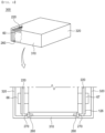
- FIG. 3 is a perspective view of a battery cell that is mounted in a battery module according to an embodiment of the present invention.
- the pouch-shaped battery or battery cell 60 includes a cell case upper part 62, a cell case lower part 61, an electrode assembly (not shown) received in the cell case upper part and the cell case lower part, a sealed portion 65 provided at edges of the cell case upper part and the cell case lower part, a pair of electrode tabs (not shown), a pair of electrode leads constituted by a positive electrode lead 66 and a negative electrode lead 67, each of which has one side electrically connected to a corresponding one of the electrode tabs and the other side protruding outward from the cell case, and an insulating film (not shown).
- each of the cell case upper part 62 and the cell case lower part 61 is provided with a pocket-shaped space portion, in which the electrode assembly is received.
- the space portion of the cell case, in which the electrode assembly is received, is formed using a laminate sheet constituted by an outer covering layer, a metal layer, and an inner covering layer.
- the inner covering layer is disposed in direct contact with the electrode assembly, and therefore the inner covering layer must exhibit high insulation properties and high resistance to an electrolyte.
- the inner covering layer must exhibit high sealability in order to hermetically isolate the cell case from the outside, i.e., a thermally-bonded sealed portion between inner layers must exhibit excellent thermal bonding strength.
- the inner covering layer may be made of a material selected from among a polyolefin-based resin, such as polypropylene, polyethylene, polyethylene acrylic acid, or polybutylene, a polyurethane resin, and a polyimide resin, which exhibit excellent chemical resistance and high sealability; however, the present invention is not limited thereto, and polypropylene, which exhibits excellent mechanical properties, such as tensile strength, rigidity, surface hardness, and impact resistance, and excellent chemical resistance, is preferably used.
- a polyolefin-based resin such as polypropylene, polyethylene, polyethylene acrylic acid, or polybutylene, a polyurethane resin, and a polyimide resin, which exhibit excellent chemical resistance and high sealability
- polypropylene which exhibits excellent mechanical properties, such as tensile strength, rigidity, surface hardness, and impact resistance, and excellent chemical resistance, is preferably used.
- the metal layer which abuts the outer covering layer, corresponds to a barrier layer configured to prevent moisture or various kinds of gas from permeating into the battery from the outside.
- An aluminum thin film which is lightweight and easily shapeable, may be used as a preferred material for the metal layer.
- the outer covering layer is provided at an outer surface of the metal layer, and the outer covering layer may be made of a heat-resistant polymer that exhibits excellent tensile strength, resistance to moisture permeation, and resistance to air transmission such that the outer covering layer exhibits high heat resistance and chemical resistance while protecting the electrode assembly.
- the outer covering layer may be made of nylon or polyethylene terephthalate; however, the present invention is not limited thereto.
- the electrode assembly which is received in the cell case upper part 62 and the cell case lower part 61, may be classified as a stacked type electrode assembly, which is configured to have a structure in which a plurality of electrodes is stacked, a jelly-roll type electrode assembly, which is configured to have a structure in which a positive electrode and a negative electrode are wound in the state in which a separator is interposed therebetween, a laminated and stacked type electrode assembly, which is configured to have a structure in which a plurality of unit cells is stacked, or a stacked and folded type electrode assembly, which is configured to have a structure in which unit cells are wound in a state of being located on a separator sheet.
- a unit cell is manufactured in order to manufacture the laminated and stacked type electrode assembly or the stacked and folded type electrode assembly, wherein the unit cell may be a mono-cell, which is configured to have a structure in which a separator is interposed between a positive electrode and a negative electrode, or a bi-cell, which is configured to have a structure in which a positive electrode, a negative electrode, and a positive electrode or a negative electrode, a positive electrode, and a negative electrode are stacked and a separator is interposed between the positive electrode and the negative electrode.
- the electrode assembly according to the present invention may have a structure in which a negative electrode, a separator, a positive electrode, a separator, and a negative electrode are stacked, and the number of positive electrodes or negative electrodes constituting the electrode assembly may be freely changed.
- a laminated and stacked type electrode assembly in which a plurality of unit cells is laminated, may be used.
- the structure of the electrode assembly described above may be applied to all electrode assemblies described in this specification.
- a positive electrode tab and a negative electrode tab are provided respectively at the positive electrode and the negative electrode of the electrode assembly, and the pair of electrode tabs is disposed so as to protrude a predetermined length outward from the cell case in a state of being connected respectively to a positive electrode lead 66 and a negative electrode lead 67 by spot welding, etc.
- the insulating film is located at an upper surface and a lower surface of each of the pair of electrode leads, more specifically at the sealed portion 65, at which the cell case upper part 62 and the cell case lower part 61 are thermally fused to each other.
- the insulating film prevents electricity generated by the electrode assembly from flowing to the cell case via the electrode leads and maintains a sealed state between the electrode leads and the cell case.
- the insulating film is preferably made of a non-conductive material that does not conduct electricity well, and an insulating tape easy to attach to the electrode leads while having a relatively small thickness is generally used; however, the present invention is not limited thereto.
- the battery cell is shown as a bidirectional battery cell having a positive electrode lead 66 and a negative electrode lead 67 located at opposite ends thereof in the figure, the present invention may also be applied to a unidirectional battery cell having a pair of electrode leads disposed so as to face in the same direction.
- thermally fused sealed portion of the pouch-shaped battery may occur due to repeated charging and discharging, i.e., the thermally fused portion may be deteriorated due to expansion pressure caused by gas generated by irreversible reaction or due to repetition of the conditions using high current such as rapid charging, whereby an electrolyte may leak from the pouch-shaped battery.
- the electrolyte may leak due to a variety of reasons, such as tear of the case by external impact or chemical corrosion.
- the electrolyte leaks from a side surface or an upper surface of the pouch-shaped battery.
- the electrolyte cannot flow to the bottom plate and is dried before that unless the electrolyte leaks from the upper surface of the pouch-shaped battery in large quantities, since the battery cells are stacked vertically, the distance therebetween is very small, and a pad may be added therebetween in some cases.
- the electrolyte leaks from opposite sides of the pouch-shaped battery, i.e., the parts of the pouch-shaped battery from which the electrode tabs protrude, the electrolyte leaks to a lower end of a busbar frame, and the electrolyte must leak in significant quantities in order for the electrolyte to flow to the separate bottom plate.
- FIG. 4 is an inner schematic view of a vertical plate of the battery module according to the present invention
- FIG. 5 is an outer schematic view of the vertical plate of the battery module according to the present invention
- FIG. 6 is a schematic view showing a configuration in which electrodes of a pouch-shaped cell are fastened to a vertical plate 200 and a battery module including an outer frame.
- the vertical plate 200 is disposed at each of left and right sides of a battery assembly of the battery module.
- a circuit part including a busbar for electrical connection is omitted from the vertical plate 200 of FIGs. 4 to 6 .
- the vertical plate 200 may include a vertical support portion 220 disposed vertically, an electrode groove 240 formed in the shape of a plurality of slits provided in a part of the vertical support portion 220 in a vertical direction, the electrode groove being configured to allow electrodes of pouch-shaped battery cells to extend therethrough, a busbar (not shown, omitted) coupled to the electrodes extending through the electrode groove 240, and a lower end support portion 260 coupled to the vertical support portion 220 along a lower perimeter thereof, the lower end support portion being formed in the shape of a horizontal band.
- the vertical plate 200 may be located on one side, or may be symmetrically located on opposite sides, depending on the shape and position of the electrodes of the battery cell.
- the outer frame 300 is a single frame configured to protect the vertical plate 200 and the pouch-shaped battery cell from the outside, and may include a monoframe 310 and a side frame 320; however, the present invention is not limited thereto since the outer frame may be modified so as to have various shapes.
- the outer frame 300 may be configured in the form of a framework made of metal, unlike the monoframe 310 of FIG. 6 , and an electrical connection unit 270, a description of which will follow, may be connected to such a framework type outer frame, in which case a separate cover may be further added.
- a lower end support portion 260 of the vertical plate 200 is fixed to a lower part of the outer frame 300.
- the electrical connection unit 270 is disposed at an upper surface of the lower end support portion 260.
- the electrical connection unit 270 is simplified and shown only as a black line.
- the electrical connection unit 270 is electrically connected to the monoframe 310, and when an electrolyte leaks from the battery cell, electrical conduction is achieved between the battery cell and the monoframe 310 via the electrical connection unit 270.
- FIG. 7 is a side schematic view of an electrical connection unit 270A or 270B according to an embodiment of the present invention
- FIG. 8 is a plan schematic view of an electrical connection unit 270A or 270C according to another embodiment of the present invention.
- the electrical connection unit 270A or 270B is constituted by coupling between an upper surface connection portion 271A, which is a conductor, and a vertical connection portion 272A or coupling between an upper surface connection portion 271B and an outer frame connection portion 273, and is spaced apart from the battery cell in a non-contact state by a predetermined distance.
- the distance may be set such that the electrical connection unit and the battery cell are electrically connected to each other when an electrolyte 280 leaks to the upper surface connection portion 271A or 271B.
- the upper surface connection portion 271A or 271B is located at a lower part at which the electrode of the battery cell 60 is disposed.
- the upper surface connection portion 271A is located an upper surface of the lower end support portion 260, and the upper surface connection portion 271A and the monoframe 310 are coupled to each other via the vertical connection portion 272A.
- the vertical connection portion 272A since the vertical connection portion 272A must be fixed to the monoframe 310 through the lower end support portion 260, the vertical connection portion may be configured in the form of a bolt or a rivet; however, the present invention is not limited thereto.
- the entirety of the electrical connection unit 270A may be configured in the form of a simple cylinder, unlike (a) of FIG. 7 .
- the upper surface connection portion 271B is directly connected to the monoframe 310 via the outer frame connection portion 273 without the vertical connection portion 272A, wherein the outer frame connection portion may be a wire or flexible flat cable (FFC) electrically connected to one surface of the monoframe 310; however, the present invention is not limited thereto.
- the upper surface connection portion 271B may be fixed to the lower end support portion 260 by adhesion.
- FIG. 8 is a plan view showing the electrical connection unit 270A located at the upper surface of the lower end support portion 260 of FIG. 7 .
- the upper surface connection portion 271A is configured as a metal band formed in the shape of a thin plate and is located at the upper surface of the lower end support portion 260, and each end of the upper surface connection portion is fixed by the vertical connection portion 272A.
- the position of the vertical connection portion 272A is not particularly limited since it is sufficient for the vertical connection portion 272A to be connected to the upper surface connection portion 271A so as to be electrically connected to the monoframe 310.
- the upper surface connection portion 271A may be modified such that the upper surface connection portion is divided into a plurality of parts, at each of which the vertical connection portion 272A is provided.
- an upper surface connection portion 271C is integrally formed with a vertical connection portion 272C, and is disposed directly under a pouch of the battery cell in one or more.
- the upper surface connection portion 271C may have various shapes, preferably a circular shape.
- FIG. 9 is a view showing a detection unit 330 configured to measure insulation resistance or voltage of the monoframe 310 according to the present invention.
- the detection unit 330 measures insulation resistance or voltage between the monoframe 310 connected to ground and an external electrode of a pouch-shaped battery cell. When measurement is performed at 500 volts for 60 seconds until leakage occurs, an insulation resistance of approximately several hundred megohms (Mohms) or more is measured. When an electrolyte 280 leaks, however, electrical conduction occurs between the upper surface connection portion 271 and the battery cell, which leads to a decrease in insulation resistance or an increase in voltage.
- the detection unit 330 configured to detect insulation resistance or voltage may be included in a BMS of a module or a BMS of a battery pack, which is not shown in FIG. 9 .
- the electrolyte 280 leaks from a plurality of pouch-shape battery cells, leakage current is generated in proportion to the number of electrically conducted pouch-shape battery cells, whereby insulation resistance is further reduced.
- the degree of leakage of the electrolyte 280 may be detected based on a decreased resistance value relative to a reference insulation resistance value.
Landscapes
- Chemical & Material Sciences (AREA)
- Chemical Kinetics & Catalysis (AREA)
- Electrochemistry (AREA)
- General Chemical & Material Sciences (AREA)
- Engineering & Computer Science (AREA)
- Manufacturing & Machinery (AREA)
- Physics & Mathematics (AREA)
- General Physics & Mathematics (AREA)
- Battery Mounting, Suspending (AREA)
- Connection Of Batteries Or Terminals (AREA)
- Secondary Cells (AREA)
Abstract
Description
- This application claims the benefit of priority to
Korean Patent Application No. 2022-0126496 filed on October 4, 2022 - The present invention relates to an electrolyte leakage detection unit using insulation resistance and a battery module including the same. More particularly, the present invention relates to a detection unit disposed in a battery module or a battery pack, the detection unit being configured to detect leakage of an electrolyte from a battery cell using insulation resistance, and a battery module or a battery pack including the detection unit.
- A secondary battery is constituted by a battery module including a plurality of battery cells connected to each other in series and/or in parallel or a battery pack including battery modules connected to each other depending on required output voltage or charge and discharge capacities.
- A pouch-shaped battery having a stacked type or stacked and folded type electrode assembly mounted in a pouch-shaped battery case made of a laminate sheet has been mainly used in a battery module or a battery pack due to low manufacturing cost and high energy density thereof.
- For the pouch-shaped battery, a laminate sheet including an outer covering layer, a metal barrier layer, and an inner adhesive layer is shaped so as to be used as a battery case. An electrode assembly and an electrolyte are received in a receiving portion formed in the laminate sheet, and the laminate sheet is sealed, whereby the pouch-shaped battery is manufactured.
- As shown in
FIG. 1 , a pouch-shaped battery 50 is configured such that anelectrode assembly 20 is mounted in a receivingportion 13 of abattery case 10 constituted by a pouch-shapedlower part 11 and a pouch-shapedupper part 12. Positive electrode andnegative electrode tabs electrode assembly 20 are welded respectively to two electrode leads 31 and 32, which are exposed out of thebattery case 10. An outer periphery of thebattery case 10 is sealed in the state in which a pair ofinsulating films 41 is provided on upper and lower surfaces of theelectrode lead 31 and a pair ofinsulating films 42 is provided on upper and lower surfaces of theelectrode lead 32. -
FIG. 1 shows the case in which the positive electrode andnegative electrode tabs FIG. 1 , the positive electrode andnegative electrode tabs electrode assembly 20. When the positive electrode andnegative electrode tabs electrode assembly 20, i.e., when the positive electrode and negative electrode tabs are located respectively in +x and -x directions of the plane parallel to the yz-plane of theelectrode assembly 20 inFIG. 1 , a folded edge of the battery case, i.e., a folded edge located along a y-axis inFIG. 1 , is rotated in a counterclockwise direction and is located in a plane located along an x-axis. - A pouch-shaped battery configured such that electrode tabs are located at opposite sides of an electrode assembly is mainly used in a battery module or a battery pack. A plurality of pouch-shaped batteries, in each of which a positive electrode tab and a negative electrode tab are provided respectively at opposite sides thereof, is vertically disposed to constitute a pouch-shaped battery cell assembly, and busbars configured to electrically connect the positive electrode tabs and the negative electrode tabs, specifically positive electrode leads and the negative electrode leads, to each other are disposed at opposite ends of the pouch-shaped battery cell assembly. The busbars disposed at the opposite ends of the pouch-shaped battery cell assembly may be electrically connected to each other.
-
FIG. 2 is an exploded perspective view schematically showing the structure of aconventional battery module 100. Referring toFIG. 2 , thebattery module 100 includes a pouch-shapedbattery cell assembly 110 constituted by a stack of pouch-shaped battery cells 111, each of which has bidirectional electrode leads 112, abusbar frame 120 constituted by a firstvertical plate 121 and a secondvertical plate 122 disposed respectively at opposite side surfaces of the pouch-shapedbattery cell assembly 110 so as to correspond to the position of the electrode leads 112 of the pouch-shaped battery cells 111 and anupper plate 123 connected to the firstvertical plate 121 and the secondvertical plate 122, the upper plate being disposed above the pouch-shapedbattery cell assembly 110, and amonoframe 130 formed in the shape of a square pipe, into an inner space of which the pouch-shapedbattery cell assembly 110 having thebusbar frame 120 mounted thereto is inserted. Aside frame 140 is then coupled to themonoframe 130, whereby thebattery module 100 is completed. - A
busbar 126 is disposed at each of the firstvertical plate 121 and the secondvertical plate 122. Thebusbar 126 is configured to connect the plurality of pouch-shaped battery cells 111 to each other in series or in parallel. Thebusbar 126 is a conductor having low impedance and high current capacity, and a plurality ofbusbars 126 is disposed side by side in a direction in which the plurality of pouch-shaped battery cells 111 is stacked to connect the pouch-shaped battery cells 111 to each other in series or in parallel. - Although the
busbar 126 is shown as a plate structure having a uniform thickness by way of example, the present invention is not limited thereto, and change to various structures capable of achieving electrical connection is possible. - In addition to the pouch-shaped battery, a cylindrical battery or a prismatic battery may also constitute a battery module or a battery pack. A plurality of cylindrical batteries or a plurality of prismatic batteries may be vertically disposed, and a busbar may be disposed at upper surfaces or lower surfaces of the batteries at which electrodes are disposed.
- After the battery cells and the busbar are connected to each other, a case configured to fix the battery cells and the busbar may be separately added to the outside.
- When each of the pouch-shaped battery, the cylindrical battery, and the prismatic battery is used in a battery module or a battery pack, leakage of an electrolyte from the battery cell may cause various problems. Leakage of the electrolyte may degrade the electrical performance of the battery module or the battery pack, and there is a danger of corrosion, short circuit, and fire outbreak due to leaked electrolyte. For a battery module having a plurality of battery cells mounted therein, early electrolyte leakage detection is very important for safety reasons.
- Patent Document 1 relates to an apparatus and method for detecting leakage of an electrolyte from a battery cell to protect a battery pack. Patent Document 1 includes an
electrolyte absorbing member 10 attached to the outside of a battery cell to absorb an electrolyte having leaked from the battery cell, the electrolyte absorbing member having characteristics of a conductor as the result of absorbing the electrolyte, apower supply unit 20 connected to opposite ends of the electrolyte absorbing member to supply power thereto, a resistance unit 30 connected between the electrolyte absorbing member and the power supply unit, a sensing unit 40 configured to sense whether current flows in the resistance unit, and acontroller 50 configured to melt and cut a fuse on a charging and discharging path of the battery pack to block charging and discharging current when the sensing unit senses that current flows in the resistance unit. - Patent Document 1 has the feature of detecting leakage of the electrolyte, thereby protecting a battery module or a battery pack; however, the overall structure of absorbing the electrolyte and sensing whether current flows is very complicated. In particular, the electrolyte absorption member must be attached separately to the outside of each battery cell, and there is a problem that a plurality of additional members takes up space and reduces energy density.
- Patent Document 2 relates to a battery module and a battery pack including the same, wherein a film-type sensor configured to detect leakage of an electrolyte is attached to opposite sides of a slit in a busbar frame. An insulating coating layer, which is made of a material configured to melt when reacting with an organic solvent, i.e., an electrolyte, is added to the outside of the film-type sensor.
- In the case of Patent Document 2, when the electrolyte leaks, the electrolyte moves to a lower end of the bus frame by gravity, whereby it is difficult to detect leakage of the electrolyte unless the electrolyte leaks in large quantities. Rather, the leaked electrolyte escapes through the slit, making early detection difficult.
- In addition, electrical connection is required for each individual position at which the sensor is attached, whereby the structure for such electrical connection is complicated, and interference with a busbar may be caused due to electrical connection.
- Patent Document 3 relates to an apparatus for detecting leakage of an electrolyte in a battery module/pack, wherein a wire parallel to a strip body including a wiring portion is embedded in a lower part of the battery module/pack, and a wire window is configured to cause a capillary effect to short-circuit two wires in case of leakage of an electrolyte, and a determination is made as to whether an electrolyte leaks from a battery through electrical resistance measurement.
- In the case of Patent Document 3, the wiring portion configured to detect the electrolyte is embedded in a separate bottom plate, and therefore and detection is possible only when the amount of the leaked electrolyte reaches a certain amount. In Patent Document 3, it is stated that detection is possible only when the amount of the leaked electrolyte exceeds 8 ml.
- It is difficult to apply a battery module or pack using a pouch-shaped battery to Patent Document 3. Since a lower surface of the pouch-shaped battery is a part that is connected without separate sealing, an electrolyte leaks from a side surface or an upper surface of the pouch-shaped battery. When the electrolyte leaks from the upper surface of the pouch-shaped battery, the electrolyte cannot flow to the bottom plate and is dried before that unless the electrolyte leaks in large quantities, since pouch-shaped battery cells are stacked vertically, the distance therebetween is very small, and a pad may be added therebetween in some cases.
- In Patent Document 3, separate embedment in the bottom plate is required, and a configuration, such as a capillary, must be added. When embedment is performed in a longitudinal direction, as in an embodiment of Patent Document 3, early detection of leakage of the electrolyte from the pouch-shaped battery is substantially impossible.
- If the electrolyte leaks from opposite sides of the pouch-shaped battery, i.e., the parts of the pouch-shaped battery from which electrode tabs protrude, the electrolyte leaks to the lower end of the busbar frame, and the electrolyte must leak in significant quantities in order for the electrolyte to flow to the separate bottom plate.
- Patent Document 3 mentions the case in which a strip-type detection groove is installed in the center of the bottom plate or is disposed along electrodes of the batteries in the battery module so as to be located directly under the electrodes, and also mentions the case in which a plurality of strip-type detection grooves is provided. In Patent Document 3, however, the shape of the strip-type detection groove is limited. In the case of a pouch-shaped battery, opposite electrodes must be coupled to the busbar frame, and therefore the strip-type detection groove of Patent Document 3 may be located only under the busbar frame. In this case, early detection of a very small amount of an electrolyte is impossible. Patent Document 3 also limits the minimally detectable amount of the electrolyte to more than 8 ml.
- It can be seen that, in the embodiment of Patent Document 3 or when the strip-type detection groove is disposed under the electrode, early detection of leakage of the electrolyte from the pouch-shaped battery is impossible. Given that the strip-type detection groove of Patent Document 3 is described as being disposed in the longitudinal direction, being disposed directly under the electrode, or being disposed in plural, it may be assumed that the case in which a cylindrical battery cell is used is considered.
- Patent Document 4 relates to a storage device capable of performing early detection of abnormality of a storage element (leakage of an electrolyte). In Patent Document 4, the storage device 1 has a plurality of
storage elements 10 each containing an electrolyte, the storage elements being configured to be charged and discharged, and a holder 30 configured to hold each of the plurality of storage elements in a predetermined plane (in an Y-Z plane) in an insulated state. The holder hasconductive members 31 and 34 exposed outward from the holder, wherein the conductive member is located with respect to each storage element in a direction in which the electrolyte is discharged from each storage element. The conductive member is coupled to asensor 100 configured to detect the conduction state and the non-conduction state of the conductive member. - In Patent Document 4, leakage of the electrolyte is detected by measuring insulation resistance, but detection is possible only when the electrolyte leaks in large amounts.
- As can be seen from the above, technology that i) is capable of performing early detection of leakage of a very small amount of an electrolyte, ii) is simple in structure, and iii) is capable of being applied without interference with the configuration of a conventional device has not yet been provided.
-
- (Patent Document 1)
Korean Registered Patent Publication No. 1383599 2014.04.03 - (Patent Document 2)
Korean Patent Application Publication No. 2021-0108269 2021.09.02 - (Patent Document 3)
Chinese Patent Application Publication No. 111337201 (2020.06.26 ) - (Patent Document 4)
Japanese Patent Application Publication No. 2014-63663 (2014.04.10 - The present invention has been made in view of the above problems, and it is an object of the present invention to provide an electrolyte leakage detection unit that i) is capable of performing early detection of leakage of a very small amount of an electrolyte, ii) is simple in structure, and iii) is capable of being applied without interference with the configuration of a conventional device and a battery module including the same.
- A battery module according to the present invention to accomplish the above object includes a battery cell (60); a vertical plate (200) including a busbar (126) configured to allow an electrode of the battery cell (60) to be electrically coupled thereto; and an outer frame (300) configured to surround the vertical plate (200) and the outside of the battery cell (60) ; at least one electrical connection unit (270) extending through the vertical plate (200), the electrical connection unit being electrically connected to the outer frame (300); and a detection unit (330) configured to measure insulation resistance or voltage of one terminal electrode of the battery module and the outer frame (300).
- Also, in the battery module according to the present invention, the vertical plate (200) may include a vertical support portion (220) disposed vertically, an electrode groove (240) formed by a plurality of slits provided in a part of the vertical support portion (220) in a vertical direction, the electrode groove being configured to allow the electrode of the battery cell to extend therethrough, a busbar (126) coupled to the electrode of extending through the electrode groove (240), and a lower end support portion (260) coupled to the vertical support portion (220) along a lower perimeter of the vertical support portion, the lower end support portion being formed in the shape of a horizontal band.
- Also, in the battery module according to the present invention, the electrical connection unit (270) may include at least one vertical connection portion (272) extending through the lower end support portion (260) and electrically connected to one end of the outer frame (300) and an upper surface connection portion (271) electrically connected to the vertical connection portion (271) and exposed on an upper surface of the lower end support portion (260) or disposed on the upper surface of the lower end support portion (260).
- Also, in the battery module according to the present invention, the electrical connection unit (270) may include at least one outer frame connection portion (273) electrically connected to one end of the outer frame (300) and an upper surface connection portion (271) electrically connected to the outer frame connection portion (273) and exposed on an upper surface of the lower end support portion (260) or disposed on the upper surface of the lower end support portion (260).
- Also, in the battery module according to the present invention, the upper surface connection portion (271) may be disposed spaced apart from the battery cell (60) in a non-contact state.
- Also, in the battery module according to the present invention, when an electrolyte (280) leaks from the battery cell (60), the upper surface connection portion (271) may be electrically connected to the battery cell (60) via the leaked electrolyte (280).
- Also, in the battery module according to the present invention, the upper surface connection portion (271) may be located at a lower part at which the electrode of the battery cell (60) is disposed.
- Also, in the battery module according to the present invention, each of the upper surface connection portion (271) and the vertical connection portion (272) may be made of a conductor.
- Also, in the battery module according to the present invention, the upper surface connection portion (271) may be a metal band formed in the shape of a thin plate and may be located at the upper surface of the lower end support portion (260) at which the electrode of the battery cell (60) is disposed.
- Also, in the battery module according to the present invention, the vertical connection portion (272) may be located and fixed at one side or opposite sides of the upper surface connection portion (271).
- Also, in the battery module according to the present invention, the upper surface connection portion may be circular and may be disposed at the upper surface of the lower end support portion (260) at which the electrode of the battery cell (60) is disposed in a state of being spaced apart from each other.
- Also, in the battery module according to the present invention, the outer frame connection portion (273) may be an electric wire configured to electrically connect the upper surface connection portion (271) and the outer frame (300) to each other.
- In addition, an electrolyte leakage detection method according to the present invention includes measuring insulation resistance or voltage of the outer frame (300) and determining that the electrolyte has leaked when the measured insulation resistance or voltage deviates from a reference range.
- The present invention may provide any possible combinations of the above solving means.
- As is apparent from the above description, in the present invention, it is possible to provide an electrolyte leakage detection unit that i) is capable of performing early detection of leakage of a very small amount of an electrolyte, ii) is relatively simple in structure since only insulation resistance or voltage of an outer frame is measured, and iii) is capable of being applied without interference with the configuration of a conventional device and a battery module including the same.
-
-
FIG. 1 is an exploded perspective view of a conventional pouch-shaped battery. -
FIG. 2 is an exploded perspective view schematically showing the structure of a conventional battery module. -
FIG. 3 is a perspective view of a pouch-shaped battery cell that is mounted in a battery module according to a preferred embodiment of the present invention. -
FIG. 4 is an inner schematic view of a vertical plate of the battery module according to the present invention. -
FIG. 5 is an outer schematic view of the vertical plate of the battery module according to the present invention. -
FIG. 6 is a schematic view showing a battery module including an outer frame according to the present invention. -
FIG. 7 is a side schematic view of an electrical connection unit according to an embodiment of the present invention. -
FIG. 8 is a plan schematic view of an electrical connection unit according to another embodiment of the present invention. -
FIG. 9 is a view showing a detection unit configured to measure insulation resistance of the outer frame according to the present invention. - Now, preferred embodiments of the present invention will be described in detail with reference to the accompanying drawings such that the preferred embodiments of the present invention can be easily implemented by a person having ordinary skill in the art to which the present invention pertains. In describing the principle of operation of the preferred embodiments of the present invention in detail, however, a detailed description of known functions and configurations incorporated herein will be omitted when the same may obscure the subject matter of the present invention.
- In addition, the same reference numbers will be used throughout the drawings to refer to parts that perform similar functions or operations. In the case in which one part is the to be connected to another part in the entire specification, not only may the one part be directly connected to the other part, but also, the one part may be indirectly connected to the other part via a further part. In addition, that a certain element is included does not mean that other elements are excluded, but means that such elements may be further included unless mentioned otherwise.
- Hereinafter, an electrolyte leakage detection unit according to the present invention and a battery module including the same will be described with reference to the accompanying drawings.
- The basic structure of the battery module according to the present invention is identical to the structure of a battery module using a conventional pouch-shaped battery.
FIG. 2 is an exploded perspective view schematically showing the structure of a conventional battery module. UnlikeFIG. 2 , the pouch-shaped battery may be modified to have electrodes disposed in only one direction as shown inFIG. 1 , and upper ends of abusbar frame 120 may not be connected to each other. - Even in the case of a pouch-shaped battery having electrodes disposed in opposite directions, the shape of the
busbar frame 120 is not limited to the shape shown in the figure, and the busbar frame may have any shape as long as opposite busbars are electrically connected to each other. Furthermore, amonoframe 130 and aside frame 140, which are shown as one example, may be modified into any shape as long as the monoframe and the side frame serve as an outer case configured to enclose the battery module. -
FIG. 3 is a perspective view of a battery cell that is mounted in a battery module according to an embodiment of the present invention. - As shown in
FIG. 3 , the pouch-shaped battery orbattery cell 60 includes a cell caseupper part 62, a cell caselower part 61, an electrode assembly (not shown) received in the cell case upper part and the cell case lower part, a sealedportion 65 provided at edges of the cell case upper part and the cell case lower part, a pair of electrode tabs (not shown), a pair of electrode leads constituted by apositive electrode lead 66 and anegative electrode lead 67, each of which has one side electrically connected to a corresponding one of the electrode tabs and the other side protruding outward from the cell case, and an insulating film (not shown). - Specifically, each of the cell case
upper part 62 and the cell caselower part 61 is provided with a pocket-shaped space portion, in which the electrode assembly is received. - The space portion of the cell case, in which the electrode assembly is received, is formed using a laminate sheet constituted by an outer covering layer, a metal layer, and an inner covering layer.
- The inner covering layer is disposed in direct contact with the electrode assembly, and therefore the inner covering layer must exhibit high insulation properties and high resistance to an electrolyte. In addition, the inner covering layer must exhibit high sealability in order to hermetically isolate the cell case from the outside, i.e., a thermally-bonded sealed portion between inner layers must exhibit excellent thermal bonding strength.
- The inner covering layer may be made of a material selected from among a polyolefin-based resin, such as polypropylene, polyethylene, polyethylene acrylic acid, or polybutylene, a polyurethane resin, and a polyimide resin, which exhibit excellent chemical resistance and high sealability; however, the present invention is not limited thereto, and polypropylene, which exhibits excellent mechanical properties, such as tensile strength, rigidity, surface hardness, and impact resistance, and excellent chemical resistance, is preferably used.
- The metal layer, which abuts the outer covering layer, corresponds to a barrier layer configured to prevent moisture or various kinds of gas from permeating into the battery from the outside. An aluminum thin film, which is lightweight and easily shapeable, may be used as a preferred material for the metal layer.
- The outer covering layer is provided at an outer surface of the metal layer, and the outer covering layer may be made of a heat-resistant polymer that exhibits excellent tensile strength, resistance to moisture permeation, and resistance to air transmission such that the outer covering layer exhibits high heat resistance and chemical resistance while protecting the electrode assembly. As an example, the outer covering layer may be made of nylon or polyethylene terephthalate; however, the present invention is not limited thereto.
- The electrode assembly, which is received in the cell case
upper part 62 and the cell caselower part 61, may be classified as a stacked type electrode assembly, which is configured to have a structure in which a plurality of electrodes is stacked, a jelly-roll type electrode assembly, which is configured to have a structure in which a positive electrode and a negative electrode are wound in the state in which a separator is interposed therebetween, a laminated and stacked type electrode assembly, which is configured to have a structure in which a plurality of unit cells is stacked, or a stacked and folded type electrode assembly, which is configured to have a structure in which unit cells are wound in a state of being located on a separator sheet. - A unit cell is manufactured in order to manufacture the laminated and stacked type electrode assembly or the stacked and folded type electrode assembly, wherein the unit cell may be a mono-cell, which is configured to have a structure in which a separator is interposed between a positive electrode and a negative electrode, or a bi-cell, which is configured to have a structure in which a positive electrode, a negative electrode, and a positive electrode or a negative electrode, a positive electrode, and a negative electrode are stacked and a separator is interposed between the positive electrode and the negative electrode.
- The electrode assembly according to the present invention may have a structure in which a negative electrode, a separator, a positive electrode, a separator, and a negative electrode are stacked, and the number of positive electrodes or negative electrodes constituting the electrode assembly may be freely changed. In addition, a laminated and stacked type electrode assembly, in which a plurality of unit cells is laminated, may be used. The structure of the electrode assembly described above may be applied to all electrode assemblies described in this specification.
- A positive electrode tab and a negative electrode tab are provided respectively at the positive electrode and the negative electrode of the electrode assembly, and the pair of electrode tabs is disposed so as to protrude a predetermined length outward from the cell case in a state of being connected respectively to a
positive electrode lead 66 and anegative electrode lead 67 by spot welding, etc. - The insulating film is located at an upper surface and a lower surface of each of the pair of electrode leads, more specifically at the sealed
portion 65, at which the cell caseupper part 62 and the cell caselower part 61 are thermally fused to each other. The insulating film prevents electricity generated by the electrode assembly from flowing to the cell case via the electrode leads and maintains a sealed state between the electrode leads and the cell case. The insulating film is preferably made of a non-conductive material that does not conduct electricity well, and an insulating tape easy to attach to the electrode leads while having a relatively small thickness is generally used; however, the present invention is not limited thereto. - Although the battery cell is shown as a bidirectional battery cell having a
positive electrode lead 66 and anegative electrode lead 67 located at opposite ends thereof in the figure, the present invention may also be applied to a unidirectional battery cell having a pair of electrode leads disposed so as to face in the same direction. - During use of the battery module, separation of the thermally fused sealed portion of the pouch-shaped battery may occur due to repeated charging and discharging, i.e., the thermally fused portion may be deteriorated due to expansion pressure caused by gas generated by irreversible reaction or due to repetition of the conditions using high current such as rapid charging, whereby an electrolyte may leak from the pouch-shaped battery.
- In addition, the electrolyte may leak due to a variety of reasons, such as tear of the case by external impact or chemical corrosion.
- Since a lower surface of the pouch-shaped battery, which is vertically disposed in the battery module, is a part that is connected without separate sealing, the electrolyte leaks from a side surface or an upper surface of the pouch-shaped battery. When the electrolyte leaks from the upper surface of the pouch-shaped battery, the electrolyte cannot flow to the bottom plate and is dried before that unless the electrolyte leaks from the upper surface of the pouch-shaped battery in large quantities, since the battery cells are stacked vertically, the distance therebetween is very small, and a pad may be added therebetween in some cases.
- If the electrolyte leaks from opposite sides of the pouch-shaped battery, i.e., the parts of the pouch-shaped battery from which the electrode tabs protrude, the electrolyte leaks to a lower end of a busbar frame, and the electrolyte must leak in significant quantities in order for the electrolyte to flow to the separate bottom plate.
-
FIG. 4 is an inner schematic view of a vertical plate of the battery module according to the present invention,FIG. 5 is an outer schematic view of the vertical plate of the battery module according to the present invention, andFIG. 6 is a schematic view showing a configuration in which electrodes of a pouch-shaped cell are fastened to avertical plate 200 and a battery module including an outer frame. - Referring to
FIGs. 4 to 6 , thevertical plate 200 is disposed at each of left and right sides of a battery assembly of the battery module. A circuit part including a busbar for electrical connection is omitted from thevertical plate 200 ofFIGs. 4 to 6 . - The
vertical plate 200 may include avertical support portion 220 disposed vertically, anelectrode groove 240 formed in the shape of a plurality of slits provided in a part of thevertical support portion 220 in a vertical direction, the electrode groove being configured to allow electrodes of pouch-shaped battery cells to extend therethrough, a busbar (not shown, omitted) coupled to the electrodes extending through theelectrode groove 240, and a lowerend support portion 260 coupled to thevertical support portion 220 along a lower perimeter thereof, the lower end support portion being formed in the shape of a horizontal band. In addition, thevertical plate 200 may be located on one side, or may be symmetrically located on opposite sides, depending on the shape and position of the electrodes of the battery cell. - The
outer frame 300 is a single frame configured to protect thevertical plate 200 and the pouch-shaped battery cell from the outside, and may include amonoframe 310 and aside frame 320; however, the present invention is not limited thereto since the outer frame may be modified so as to have various shapes. Theouter frame 300 may be configured in the form of a framework made of metal, unlike themonoframe 310 ofFIG. 6 , and anelectrical connection unit 270, a description of which will follow, may be connected to such a framework type outer frame, in which case a separate cover may be further added. A lowerend support portion 260 of thevertical plate 200 is fixed to a lower part of theouter frame 300. - The
electrical connection unit 270 according to the present invention is disposed at an upper surface of the lowerend support portion 260. InFIG. 4 , theelectrical connection unit 270 is simplified and shown only as a black line. - Referring to
FIG. 6 , theelectrical connection unit 270 is electrically connected to themonoframe 310, and when an electrolyte leaks from the battery cell, electrical conduction is achieved between the battery cell and themonoframe 310 via theelectrical connection unit 270. - In a normal state without electrolyte leakage, a certain distance is maintained between the
electrical connection unit 270 and the battery cell, whereby insulation is achieved therebetween and the insulation from themonoframe 310 is also maintained. If themonoframe 310 and the battery cell are electrical conducted to each other due to leakage, however, leakage current may occur, whereby insulation resistance or voltage is changed. - Hereinafter, a specific embodiment of the
electrical connection unit 270 and a method of measuring insulation resistance or voltage will be described in detail with reference toFIGs. 7 to 9 . -
FIG. 7 is a side schematic view of anelectrical connection unit FIG. 8 is a plan schematic view of anelectrical connection unit - Referring to
FIG. 7 , theelectrical connection unit surface connection portion 271A, which is a conductor, and avertical connection portion 272A or coupling between an uppersurface connection portion 271B and an outerframe connection portion 273, and is spaced apart from the battery cell in a non-contact state by a predetermined distance. Here, the distance may be set such that the electrical connection unit and the battery cell are electrically connected to each other when anelectrolyte 280 leaks to the uppersurface connection portion surface connection portion battery cell 60 is disposed. - Specifically, referring to (a) of
FIG. 7 , the uppersurface connection portion 271A is located an upper surface of the lowerend support portion 260, and the uppersurface connection portion 271A and themonoframe 310 are coupled to each other via thevertical connection portion 272A. Meanwhile, since thevertical connection portion 272A must be fixed to themonoframe 310 through the lowerend support portion 260, the vertical connection portion may be configured in the form of a bolt or a rivet; however, the present invention is not limited thereto. The entirety of theelectrical connection unit 270A may be configured in the form of a simple cylinder, unlike (a) ofFIG. 7 . - Referring to (b) of
FIG. 7 , which shows theelectrical connection unit 270B according to the modification of the present invention, the uppersurface connection portion 271B is directly connected to themonoframe 310 via the outerframe connection portion 273 without thevertical connection portion 272A, wherein the outer frame connection portion may be a wire or flexible flat cable (FFC) electrically connected to one surface of themonoframe 310; however, the present invention is not limited thereto. At this time, the uppersurface connection portion 271B may be fixed to the lowerend support portion 260 by adhesion. -
FIG. 8 is a plan view showing theelectrical connection unit 270A located at the upper surface of the lowerend support portion 260 ofFIG. 7 . - Referring to (a) of
FIG. 8 , the uppersurface connection portion 271A is configured as a metal band formed in the shape of a thin plate and is located at the upper surface of the lowerend support portion 260, and each end of the upper surface connection portion is fixed by thevertical connection portion 272A. Here, the position of thevertical connection portion 272A is not particularly limited since it is sufficient for thevertical connection portion 272A to be connected to the uppersurface connection portion 271A so as to be electrically connected to themonoframe 310. In (a) ofFIG. 8 , the uppersurface connection portion 271A may be modified such that the upper surface connection portion is divided into a plurality of parts, at each of which thevertical connection portion 272A is provided. - Referring to (b) of
FIG. 8 , an uppersurface connection portion 271C is integrally formed with avertical connection portion 272C, and is disposed directly under a pouch of the battery cell in one or more. In addition, the uppersurface connection portion 271C may have various shapes, preferably a circular shape. -
FIG. 9 is a view showing adetection unit 330 configured to measure insulation resistance or voltage of themonoframe 310 according to the present invention. - Referring to
FIG. 9 , thedetection unit 330 measures insulation resistance or voltage between themonoframe 310 connected to ground and an external electrode of a pouch-shaped battery cell. When measurement is performed at 500 volts for 60 seconds until leakage occurs, an insulation resistance of approximately several hundred megohms (Mohms) or more is measured. When anelectrolyte 280 leaks, however, electrical conduction occurs between the upper surface connection portion 271 and the battery cell, which leads to a decrease in insulation resistance or an increase in voltage. Thedetection unit 330 configured to detect insulation resistance or voltage may be included in a BMS of a module or a BMS of a battery pack, which is not shown inFIG. 9 . - In addition, when the
electrolyte 280 leaks from a plurality of pouch-shape battery cells, leakage current is generated in proportion to the number of electrically conducted pouch-shape battery cells, whereby insulation resistance is further reduced. The degree of leakage of theelectrolyte 280 may be detected based on a decreased resistance value relative to a reference insulation resistance value. - Although the specific details of the present invention have been described in detail, those skilled in the art will appreciate that the detailed description thereof discloses only preferred embodiments of the present invention and thus does not limit the scope of the present invention. Accordingly, those skilled in the art will appreciate that various changes and modifications are possible, without departing from the category and the technical idea of the present invention, and it will be obvious that such changes and modifications fall within the scope of the appended claims.
-
- 10: Battery case
- 11, 61: Lower parts
- 12, 62: Upper parts
- 13: Receiving portion
- 20: Electrode assembly
- 21, 22: Electrode tabs
- 31, 32, 66, 67: Electrode leads
- 41, 42: Insulating films
- 50, 60: Pouch-shaped batteries
- 65: Sealed portion
- 100: Battery module
- 110: Cell assembly
- 111: Pouch-shaped battery
- 112: Electrode lead
- 120: Busbar frame
- 121, 122: Vertical plates
- 123: Upper plate
- 126: Busbar
- 130, 310: Monoframes
- 140, 320: Side frames
- 200: Vertical plate
- 220: Vertical support portion
- 240: Electrode groove
- 260: Lower end support portion
- 270, 270A, 270B, 270C: Electrical connection units
- 271A, 271B, 271C: Upper surface connection portions
- 272A, 272C: Vertical connection portions
- 273: Outer frame connection portion
- 280: Electrolyte
- 300: Outer frame
- 330: Detection unit
Claims (13)
- A battery module comprising:a battery cell;a vertical plate comprising a busbar configured to allow an electrode of the battery cell to be electrically coupled thereto; andan outer frame configured to surround the vertical plate and an outside of the battery cell;at least one electrical connection unit extending through the vertical plate, the electrical connection unit being electrically connected to the outer frame; anda detection unit configured to measure insulation resistance or voltage of one terminal electrode of the battery module and the outer frame.
- The battery module according to claim 1, wherein the vertical plate comprises:a vertical support portion disposed vertically;an electrode groove formed by a plurality of slits provided in a part of the vertical support portion in a vertical direction, the electrode groove being configured to allow the electrode of the battery cell to extend therethrough;a busbar coupled to the electrode of extending through the electrode groove; anda lower end support portion coupled to the vertical support portion along a lower perimeter of the vertical support portion, the lower end support portion being in the shape of a horizontal band.
- The battery module according to claim 2, wherein the electrical connection unit comprises:at least one vertical connection portion extending through the lower end support portion and electrically connected to one end of the outer frame; andan upper surface connection portion electrically connected to the vertical connection portion and exposed on an upper surface of the lower end support portion or disposed on the upper surface of the lower end support portion.
- The battery module according to claim 2, wherein the electrical connection unit comprises:at least one outer frame connection portion electrically connected to one end of the outer frame; andan upper surface connection portion electrically connected to the outer frame connection portion and exposed on an upper surface of the lower end support portion or disposed on the upper surface of the lower end support portion.
- The battery module according to claim 3 or 4, wherein the upper surface connection portion is disposed spaced apart from the battery cell in a non-contact state.
- The battery module according to claim 3 or 4, wherein, when an electrolyte leaks from the battery cell, the upper surface connection portion is electrically connected to the battery cell via the leaked electrolyte.
- The battery module according to claim 3 or 4, wherein the upper surface connection portion is located at a lower part at which the electrode of the battery cell is disposed.
- The battery module according to claim 3 or 4, wherein each of the upper surface connection portion and the vertical connection portion is made of a conductor.
- The battery module according to claim 3 or 4, wherein the upper surface connection portion is a metal band formed in the shape of a thin plate and is located at the upper surface of the lower end support portion at which the electrode of the battery cell is disposed.
- The battery module according to claim 9, wherein the vertical connection portion is located and fixed at one side or opposite sides of the upper surface connection portion.
- The battery module according to claim 3 or 4, wherein the upper surface connection portion is circular and is disposed at the upper surface of the lower end support portion at which the electrode of the battery cell is disposed in a state of being spaced apart from each other.
- The battery module according to claim 4, wherein the outer frame connection portion is an electric wire configured to electrically connect the upper surface connection portion and the outer frame to each other.
- A method of detecting leakage of an electrolyte from a battery cell using the battery module according to any one of claims 1 to 12, wherein insulation resistance or voltage of the outer frame is measured, and when the measured insulation resistance or voltage deviates from a reference range, a determination is made that the electrolyte has leaked.
Applications Claiming Priority (2)
| Application Number | Priority Date | Filing Date | Title |
|---|---|---|---|
| KR1020220126496A KR20240047176A (en) | 2022-10-04 | 2022-10-04 | Electrolyte leakage detection unit using insulation resistance and battery module comprising the same |
| PCT/KR2023/014970 WO2024076099A1 (en) | 2022-10-04 | 2023-09-27 | Electrolyte leakage detection unit using insulation resistance, and battery module comprising same |
Publications (2)
| Publication Number | Publication Date |
|---|---|
| EP4429014A1 true EP4429014A1 (en) | 2024-09-11 |
| EP4429014A4 EP4429014A4 (en) | 2025-08-06 |
Family
ID=90608696
Family Applications (1)
| Application Number | Title | Priority Date | Filing Date |
|---|---|---|---|
| EP23875163.0A Pending EP4429014A4 (en) | 2022-10-04 | 2023-09-27 | ELECTROLYTE LEAK DETECTION UNIT WITH INSULATION RESISTOR AND BATTERY MODULE |
Country Status (6)
| Country | Link |
|---|---|
| US (1) | US20250149649A1 (en) |
| EP (1) | EP4429014A4 (en) |
| JP (1) | JP7794497B2 (en) |
| KR (1) | KR20240047176A (en) |
| CN (1) | CN118285017A (en) |
| WO (1) | WO2024076099A1 (en) |
Family Cites Families (13)
| Publication number | Priority date | Publication date | Assignee | Title |
|---|---|---|---|---|
| JP4810745B2 (en) * | 2000-12-21 | 2011-11-09 | ソニー株式会社 | Battery pack with electrolyte leakage detection function |
| KR101383599B1 (en) | 2009-11-13 | 2014-04-10 | 주식회사 엘지화학 | Apparatus and method for protecting battery pack by detecting electrolyte leakage |
| JP5880373B2 (en) | 2012-09-21 | 2016-03-09 | トヨタ自動車株式会社 | Power storage device |
| JP2016001525A (en) * | 2014-06-11 | 2016-01-07 | 株式会社Nttファシリティーズ | Liquid leak detection system |
| CN110495012A (en) * | 2017-11-22 | 2019-11-22 | Tdk株式会社 | Battery |
| KR102340898B1 (en) * | 2018-03-30 | 2021-12-16 | 주식회사 엘지에너지솔루션 | Battery module having a bus bar frame with improved assembly |
| JP7047548B2 (en) * | 2018-04-02 | 2022-04-05 | 日産自動車株式会社 | Rechargeable battery system |
| KR102818505B1 (en) * | 2019-08-26 | 2025-06-10 | 주식회사 엘지에너지솔루션 | Detection device for electrolyte and moving device of secondary battery including the same |
| KR102890751B1 (en) | 2020-02-25 | 2025-11-24 | 주식회사 엘지에너지솔루션 | Battery module and battery pack including the same |
| EP3872889B1 (en) * | 2020-02-25 | 2023-08-23 | Samsung SDI Co., Ltd. | A battery system, a method for leakage detection inside a battery system and a vehicle including a battery system |
| CN111337201A (en) | 2020-04-26 | 2020-06-26 | 江苏塔菲尔动力系统有限公司 | Liquid leakage detection device, battery module and battery pack thereof |
| KR102479117B1 (en) | 2021-03-09 | 2022-12-19 | 하용간 | Sludge Weight Measuring Method, Measurer and a Settling Tank Using the Same |
| KR102927974B1 (en) * | 2021-12-17 | 2026-02-20 | 주식회사 엘지에너지솔루션 | Battery module with electrolyte leakage detection function and battery pack comprising the same |
-
2022
- 2022-10-04 KR KR1020220126496A patent/KR20240047176A/en active Pending
-
2023
- 2023-09-27 WO PCT/KR2023/014970 patent/WO2024076099A1/en not_active Ceased
- 2023-09-27 JP JP2024528473A patent/JP7794497B2/en active Active
- 2023-09-27 US US18/833,434 patent/US20250149649A1/en active Pending
- 2023-09-27 EP EP23875163.0A patent/EP4429014A4/en active Pending
- 2023-09-27 CN CN202380014631.6A patent/CN118285017A/en active Pending
Also Published As
| Publication number | Publication date |
|---|---|
| WO2024076099A1 (en) | 2024-04-11 |
| EP4429014A4 (en) | 2025-08-06 |
| US20250149649A1 (en) | 2025-05-08 |
| CN118285017A (en) | 2024-07-02 |
| KR20240047176A (en) | 2024-04-12 |
| JP7794497B2 (en) | 2026-01-06 |
| JP2024542445A (en) | 2024-11-15 |
Similar Documents
| Publication | Publication Date | Title |
|---|---|---|
| KR101577387B1 (en) | Secondary battery, and secondary battery module and secondary battery pack comprising the same | |
| US12603330B2 (en) | Battery module having electrolytic solution leakage detection function and battery pack including the same | |
| KR20150065280A (en) | Battery pack | |
| US9240618B2 (en) | Rechargeable battery and battery module | |
| KR20240092917A (en) | Battery module and battery pack including the same | |
| KR20140107084A (en) | Rechargeable battery | |
| EP4429014A1 (en) | Electrolyte leakage detection unit using insulation resistance, and battery module comprising same | |
| US20240097290A1 (en) | Pouch-Shaped Battery Cell Including Sensing Member and Battery Module Including the Same | |
| KR102917136B1 (en) | Pouch type secondary battery and battery module including the same | |
| KR20240035030A (en) | Pouch-Type Battery Cell and Battery Module Including The Same | |
| US20250123176A1 (en) | Electrolyte leakage detection unit and battery module including the same | |
| EP4243194B1 (en) | Pouch-shaped battery cell with improved thermal stability | |
| KR102916647B1 (en) | Pouch type secondary battery with improved safety and Battery module including the same | |
| EP4283758A1 (en) | Battery module with pressure sensor for thermal runaway detection | |
| KR20250009854A (en) | Battery module and battery pack including the same | |
| KR20240101187A (en) | Battery cell and battery module including the same |
Legal Events
| Date | Code | Title | Description |
|---|---|---|---|
| STAA | Information on the status of an ep patent application or granted ep patent |
Free format text: STATUS: THE INTERNATIONAL PUBLICATION HAS BEEN MADE |
|
| PUAI | Public reference made under article 153(3) epc to a published international application that has entered the european phase |
Free format text: ORIGINAL CODE: 0009012 |
|
| STAA | Information on the status of an ep patent application or granted ep patent |
Free format text: STATUS: REQUEST FOR EXAMINATION WAS MADE |
|
| 17P | Request for examination filed |
Effective date: 20240607 |
|
| AK | Designated contracting states |
Kind code of ref document: A1 Designated state(s): AL AT BE BG CH CY CZ DE DK EE ES FI FR GB GR HR HU IE IS IT LI LT LU LV MC ME MK MT NL NO PL PT RO RS SE SI SK SM TR |
|
| A4 | Supplementary search report drawn up and despatched |
Effective date: 20250704 |
|
| RIC1 | Information provided on ipc code assigned before grant |
Ipc: H01M 50/569 20210101AFI20250630BHEP Ipc: H01M 50/502 20210101ALI20250630BHEP Ipc: H01M 50/141 20210101ALI20250630BHEP Ipc: H01M 50/211 20210101ALI20250630BHEP Ipc: H01M 10/42 20060101ALI20250630BHEP Ipc: H01M 10/48 20060101ALI20250630BHEP Ipc: H01M 50/503 20210101ALI20250630BHEP |
|
| DAV | Request for validation of the european patent (deleted) | ||
| DAX | Request for extension of the european patent (deleted) | ||
| GRAP | Despatch of communication of intention to grant a patent |
Free format text: ORIGINAL CODE: EPIDOSNIGR1 |
|
| STAA | Information on the status of an ep patent application or granted ep patent |
Free format text: STATUS: GRANT OF PATENT IS INTENDED |
|
| INTG | Intention to grant announced |
Effective date: 20260209 |
|
| P01 | Opt-out of the competence of the unified patent court (upc) registered |
Free format text: CASE NUMBER: UPC_APP_0009405_4429014/2026 Effective date: 20260311 |
|
| GRAS | Grant fee paid |
Free format text: ORIGINAL CODE: EPIDOSNIGR3 |
|
| GRAA | (expected) grant |
Free format text: ORIGINAL CODE: 0009210 |
|
| STAA | Information on the status of an ep patent application or granted ep patent |
Free format text: STATUS: THE PATENT HAS BEEN GRANTED |