EP4429013A1 - Stack-type electrode assembly with improved cell capacity - Google Patents
Stack-type electrode assembly with improved cell capacity Download PDFInfo
- Publication number
- EP4429013A1 EP4429013A1 EP23853010.9A EP23853010A EP4429013A1 EP 4429013 A1 EP4429013 A1 EP 4429013A1 EP 23853010 A EP23853010 A EP 23853010A EP 4429013 A1 EP4429013 A1 EP 4429013A1
- Authority
- EP
- European Patent Office
- Prior art keywords
- positive
- negative
- electrode assembly
- stack
- current collector
- Prior art date
- Legal status (The legal status is an assumption and is not a legal conclusion. Google has not performed a legal analysis and makes no representation as to the accuracy of the status listed.)
- Pending
Links
Images


Classifications
-
- H—ELECTRICITY
- H01—ELECTRIC ELEMENTS
- H01M—PROCESSES OR MEANS, e.g. BATTERIES, FOR THE DIRECT CONVERSION OF CHEMICAL ENERGY INTO ELECTRICAL ENERGY
- H01M50/00—Constructional details or processes of manufacture of the non-active parts of electrochemical cells other than fuel cells, e.g. hybrid cells
- H01M50/20—Mountings; Secondary casings or frames; Racks, modules or packs; Suspension devices; Shock absorbers; Transport or carrying devices; Holders
- H01M50/204—Racks, modules or packs for multiple batteries or multiple cells
- H01M50/207—Racks, modules or packs for multiple batteries or multiple cells characterised by their shape
- H01M50/209—Racks, modules or packs for multiple batteries or multiple cells characterised by their shape adapted for prismatic or rectangular cells
-
- H—ELECTRICITY
- H01—ELECTRIC ELEMENTS
- H01M—PROCESSES OR MEANS, e.g. BATTERIES, FOR THE DIRECT CONVERSION OF CHEMICAL ENERGY INTO ELECTRICAL ENERGY
- H01M50/00—Constructional details or processes of manufacture of the non-active parts of electrochemical cells other than fuel cells, e.g. hybrid cells
- H01M50/50—Current conducting connections for cells or batteries
- H01M50/531—Electrode connections inside a battery casing
- H01M50/533—Electrode connections inside a battery casing characterised by the shape of the leads or tabs
-
- H—ELECTRICITY
- H01—ELECTRIC ELEMENTS
- H01M—PROCESSES OR MEANS, e.g. BATTERIES, FOR THE DIRECT CONVERSION OF CHEMICAL ENERGY INTO ELECTRICAL ENERGY
- H01M50/00—Constructional details or processes of manufacture of the non-active parts of electrochemical cells other than fuel cells, e.g. hybrid cells
- H01M50/50—Current conducting connections for cells or batteries
- H01M50/531—Electrode connections inside a battery casing
- H01M50/54—Connection of several leads or tabs of plate-like electrode stacks, e.g. electrode pole straps or bridges
-
- H—ELECTRICITY
- H01—ELECTRIC ELEMENTS
- H01M—PROCESSES OR MEANS, e.g. BATTERIES, FOR THE DIRECT CONVERSION OF CHEMICAL ENERGY INTO ELECTRICAL ENERGY
- H01M50/00—Constructional details or processes of manufacture of the non-active parts of electrochemical cells other than fuel cells, e.g. hybrid cells
- H01M50/50—Current conducting connections for cells or batteries
- H01M50/543—Terminals
- H01M50/547—Terminals characterised by the disposition of the terminals on the cells
- H01M50/55—Terminals characterised by the disposition of the terminals on the cells on the same side of the cell
-
- H—ELECTRICITY
- H01—ELECTRIC ELEMENTS
- H01M—PROCESSES OR MEANS, e.g. BATTERIES, FOR THE DIRECT CONVERSION OF CHEMICAL ENERGY INTO ELECTRICAL ENERGY
- H01M50/00—Constructional details or processes of manufacture of the non-active parts of electrochemical cells other than fuel cells, e.g. hybrid cells
- H01M50/60—Arrangements or processes for filling or topping-up with liquids; Arrangements or processes for draining liquids from casings
- H01M50/609—Arrangements or processes for filling with liquid, e.g. electrolytes
-
- Y—GENERAL TAGGING OF NEW TECHNOLOGICAL DEVELOPMENTS; GENERAL TAGGING OF CROSS-SECTIONAL TECHNOLOGIES SPANNING OVER SEVERAL SECTIONS OF THE IPC; TECHNICAL SUBJECTS COVERED BY FORMER USPC CROSS-REFERENCE ART COLLECTIONS [XRACs] AND DIGESTS
- Y02—TECHNOLOGIES OR APPLICATIONS FOR MITIGATION OR ADAPTATION AGAINST CLIMATE CHANGE
- Y02E—REDUCTION OF GREENHOUSE GAS [GHG] EMISSIONS, RELATED TO ENERGY GENERATION, TRANSMISSION OR DISTRIBUTION
- Y02E60/00—Enabling technologies; Technologies with a potential or indirect contribution to GHG emissions mitigation
- Y02E60/10—Energy storage using batteries
-
- Y—GENERAL TAGGING OF NEW TECHNOLOGICAL DEVELOPMENTS; GENERAL TAGGING OF CROSS-SECTIONAL TECHNOLOGIES SPANNING OVER SEVERAL SECTIONS OF THE IPC; TECHNICAL SUBJECTS COVERED BY FORMER USPC CROSS-REFERENCE ART COLLECTIONS [XRACs] AND DIGESTS
- Y02—TECHNOLOGIES OR APPLICATIONS FOR MITIGATION OR ADAPTATION AGAINST CLIMATE CHANGE
- Y02P—CLIMATE CHANGE MITIGATION TECHNOLOGIES IN THE PRODUCTION OR PROCESSING OF GOODS
- Y02P70/00—Climate change mitigation technologies in the production process for final industrial or consumer products
- Y02P70/50—Manufacturing or production processes characterised by the final manufactured product
Definitions
- the present invention relates to a stack-type electrode assembly, and to a technique for improving the practical capacity of a stack-type electrode assembly by shortening the length of a foil tab of a stack-type electrode assembly, thereby reducing the area occupied by a non-coated part.
- secondary batteries can be recharged, and they have been heavily researched and developed in recent years due to their potential for miniaturization and large capacity.
- the demand for secondary batteries as an energy source is increasing rapidly due to the technological development and increasing demand for mobile devices, electric vehicles, and energy storage systems, which are emerging in response to the need for environmental protection.
- Secondary batteries are categorized into coin-type cells, cylindrical cells, prismatic cells, and pouch-type cells based on the shape of the cell case.
- an electrode assembly mounted inside the battery case is a charge and dischargeable power generator consisting of a laminated structure of electrodes and separators.
- Electrode assemblies can be roughly categorized into Jellyroll type, which is wound by interposing a separator between a positive electrode and negative electrode of an active material-coated sheet, Stack-type in which a plurality of positive electrodes and negative electrodes is sequentially stacked with a separator interposed therebetween, and Stack & Folding type in which stack-type unit cells are wound with a long separator film.
- the stack-type electrode assembly consists of a number of unit cells stacked in a stack structure, with separators placed between the positive electrodes and negative electrodes, and each unit cell is provided with its own foil tab, including a positive electrode tab and a negative electrode tab.
- the foil tabs are formed by performing a punching process on a non-coated part of the positive electrode and negative electrode, where an active material is not applied. These foil tabs serve as the entrance and exit for electrical connections to the electrode assembly, and a plurality of foil tabs are welded to a current collector and tied together as one.
- the lengthening of the foil tabs means an increase in the width of the non-coated part in both the positive electrode and negative electrode. As the non-coated part without the active material increase, the actual capacity based on an electrode assembly of the same size decreases.
- the present disclosure provides a solution for effective welding of a plurality of foil tabs to a current collector without increasing the length of the foil tabs, in line with the trend towards medium and large capacities of secondary batteries.
- the present disclosure provides an electrode assembly which may include a stack-type electrode assembly; a plurality of positive electrode tabs located at a first end of the stack-type electrode assembly in a width direction; and a plurality of negative electrode tabs located at a second end of the stack-type electrode assembly in the width direction; and a positive electrode current collector and a negative electrode current collector electrically connected to the plurality of positive electrode tabs and to the plurality of negative electrode tabs, respectively, wherein: an end of each of the plurality of positive electrode tabs and an end of each of the plurality of negative electrode tabs are individually bonded to the positive electrode current collector and to the negative electrode current collector, respectively.
- An end of each of the positive electrode tabs and an end of each of the negative electrode tabs may include a bending portion, and the bending portion of each of the positive electrode tabs and the bending portion of each of the negative electrode tabs may be individually bonded to the positive electrode current collector and the negative electrode current collector, respectively.
- each bending portion of the positive electrode tabs and each bending portion of the negative electrode tabs may be directly bonded to a facing surface of the positive electrode current collector and a facing surface of the negative electrode current collector, respectively.
- the positive electrode tabs may be arranged in a row at a substantially equal height with respect to the stack-type electrode assembly; and the negative electrode tabs may be arranged in a row at a substantially equal height with respect to the stack-type electrode assembly.
- the positive electrode tabs may form a plurality of positive tab groups, each positive tab group may be arranged in a row at a different height with respect to the stack-type electrode assembly; and the negative electrode tabs may form a plurality of negative tab groups, each negative tab group may be arranged in a row at a different height with respect to the stack-type electrode assembly.
- the stack-type electrode assembly may include a plurality of unit cells arranged in a thickness direction; each positive tab group of the plurality of positive tab groups may comprise the positive electrode tabs of a plurality of adjacent unit cells of the stack-type electrode assembly; and each negative tab group of the plurality of negative tab groups may comprise the negative electrode tabs of a plurality of adjacent unit cells of the stack-type electrode assembly.
- the positive electrode current collector may include a plurality of positive branch current collectors, each positive branch current collector may correspond to one of the positive tab groups in the plurality of positive tab groups; and the negative electrode current collector may include a plurality of negative branch current collectors, each negative branch current collector may correspond to one of the negative tab groups in the plurality of negative tab groups.
- the plurality of positive branch current collectors may be arranged in parallel with respect to the thickness direction of the stack-type electrode assembly, each of the positive branch current collectors may have extend in a different height according to a height of one of the positive tab groups in the plurality of positive tab groups; and the plurality of negative branch current collectors may be arranged in parallel with respect to the thickness direction of the stack-type electrode assembly, each of the negative branch current collectors may extend in a different height according to a height of one of the negative tab groups in the plurality of negative tab groups.
- each positive tab group of the plurality of positive tab groups may comprise at least one non-contiguous pair of positive electrode tabs; and each negative tab group of the plurality of negative tab groups may comprise at least one non-contiguous pair of negative electrode tabs.
- the positive electrode tabs of adjacent unit cells of the stack-type electrode assembly may be arranged in a row at a different height with respect to the stack-type electrode assembly; and the negative electrode tabs of adjacent unit cells of the stack-type electrode assembly may be arranged in a row at a different height with respect to the stack-type electrode assembly.
- each of the plurality of positive branch current collectors may include a first portion extending in the thickness direction of the stack-type electrode assembly, wherein the first portions of each of the plurality of positive branch current collectors may be arranged in parallel with respect to a height direction of the stack-type electrode assembly; each of the plurality of positive branch current collectors may include a second portion extending in the height direction of the stack-type electrode assembly according to a height of one of the positive tab groups in the plurality of plurality of positive tab groups; each of the plurality of negative branch current collectors may include a first portion extending in the thickness direction of the stack-type electrode assembly, wherein the first portions of each of the plurality of negative branch current collectors may be arranged in parallel with respect to the height direction of the stack-type electrode assembly; and each of the plurality of negative branch current collectors may include a second portion extending in the height direction of the stack-type electrode assembly according to a height of one of the negative tab groups in the plurality of plurality of negative tab groups.
- the present disclosure may provide a prismatic secondary battery including: a case; an electrode assembly, such as those disclosed herein, stored inside the case; a cap plate coupled to the case, the cap plate including a positive terminal and a negative terminal, wherein the positive terminal and the negative terminal are electrically connected to the positive electrode current collector and the negative electrode current collector of the electrode assembly, respectively; and an electrolyte inside the case.
- a stack-type electrode assembly of the present disclosure with the aforementioned configuration not only resolves the issue of the lengthening of foil tabs that occurs when a plurality of foil tabs are tack-welded and then welded to the current collector, as in conventional methods, by individually bonding each positive and negative electrode tab to the positive electrode current collector and negative electrode current collector, but it also improves the electrical conductivity of the stack-type electrode assembly.
- the positive tabs and negative tabs each have a bending portion at their ends, and these bending portions are individually bonded to the positive electrode current collector and negative electrode current collector. Through the bending portion, sufficient welding area at the ends of the foil tabs may be secured, thereby preventing issues such as the foil tabs from shorting in the current collector due to insufficient welding strength.
- the present disclosure provides an electrode assembly that includes a stack-type electrode assembly, and a positive electrode current collector and a negative electrode current collector.
- the stack-type electrode assembly is a plurality of unit cells stacked in a stack structure with a separator interposed between the positive electrode and negative electrode, with a plurality of positive electrode tabs and a plurality of negative electrode tabs formed at each end in the width direction. That is, the positive electrode tabs and negative electrode tabs are separated from each other on the sides of the stack-type electrode assembly.
- the positive electrode current collector and the negative electrode current collector are each a component of conductive material to which a plurality of positive electrode tabs and a plurality of negative electrode tabs are electrically connected.
- the stack-type electrode assembly can be stored in the case of a prismatic secondary battery and wiring to the positive and negative electrode terminals is facilitated.
- the ends of the positive electrode tabs and negative electrode tabs are individually bonded to the positive electrode current collector and negative electrode current collector, respectively.
- each positive electrode tab and negative electrode tab are independently bonded to the positive electrode current collector and negative electrode current collector, it not only solves the problem of the foil tabs lengthening due to tack welding of a plurality of foil tabs followed by re-welding to the current collector, as in conventional methods, but also enables performance improvements such as electrical conductivity performance in the stack-type electrode assembly, for example, increased rated current or reduced resistance, and the like.
- the positive electrode tabs and negative electrode tabs are each provided with a bending portions at their ends, and the bending portions of the positive electrode tabs and negative electrode tabs are individually bonded to the positive electrode current collectors and negative electrode current collectors, respectively. Through the bending portion, sufficient welding area at the ends of the foil tabs may be secured, thereby preventing issues such as the foil tabs from shorting in the current collector due to insufficient welding strength.
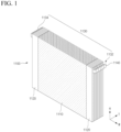
- FIG. 1 is a drawing illustrating a stack-type electrode assembly 1100 according to a configuration of the electrode assembly 1000 of the present disclosure.
- the stack-type electrode assembly 1100 is a plurality of unit cells stacked in sequence along one direction (thickness direction) with a separator interposed between the positive electrode and negative electrode, with a plurality of positive electrode tabs 1132 and a plurality of negative electrode tabs 1134 formed at each end of the width direction W.
- the positive electrode tabs 1132 and negative electrode tabs 1134 are collectively referred to as foil tabs 1130, and are formed by performing a punching process on a non-coated part 1120, which has no active material applied at the positive electrode and negative electrode, respectively.
- the illustrated stack-type electrode assembly 1100 has a coated part 1110 to which an active material is applied in the center part, and non-coated parts 1120 are arranged on both sides of the coated part 1110, and accordingly, the positive electrode tabs 1132 and negative electrode tabs 1134, which are punched on the non-coated parts 1120, are of different polarity and separately arranged on both sides of the stack-type electrode assembly 1100.
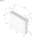
- FIG. 2 is a drawing illustrating the structure in which the current collector 1200 is coupled to the stack-type electrode assembly 1100 of FIG. 1
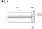
- FIG. 3 is a drawing illustrating a cross-section of the stack-type electrode assembly 1100 coupled to the current collector 1200.
- the ends of the positive electrode tabs 1132 and negative electrode tabs 1134 are individually bonded to the positive electrode current collector 1210 and the negative electrode current collector 1220, respectively.
- a plurality of foil tabs 1130 (positive electrode tabs and negative electrode tabs) provided on the stack-type electrode assembly 1100 are tack welded to structurally and electrically interconnect and then re-welded to the current collector 1200, thereby requiring that the foil tabs 1130 be sufficiently long as the distance from the stack-type electrode assembly 1100 to the current collector 1200 increases.
- the electrode assembly 1000 of the present disclosure minimizes the distance from the stack-type electrode assembly 1100 to the current collector 1200 as each of the positive electrode tabs 1132 and negative electrode tabs 1134 are independently welded to the positive electrode current collector 1210 and negative electrode current collector 1220, thereby increasing the substantial capacity based on the same size stack-type electrode assembly 1100 by shortening the length of the foil tabs 1130 in which a non-coated part 1120 without an active material is processed.
- the individual foil tabs 1130 are welded directly to the current collector 1200, a sufficient conduction area can be secured to carry a high current, and thus improved conduction performance, such as an increase in rated current and a decrease in resistance, can be obtained.
- the positive electrode tab 1132 and the negative electrode tab 1134 each have a bending portion 1140 at their ends, and the bending portion 1140 of the positive electrode tab 1132 and the negative electrode tab 1134 are individually bonded to the positive electrode current collector 1210 and the negative electrode current collector 1220, respectively. Furthermore, each of the bending portions 1140 of the positive electrode tab 1132 and the negative electrode tab 1134 can be directly bonded to a facing surface of the positive electrode current collector 1210 and the negative electrode current collector 1220, without a separate conducting medium.
- the positive electrode tab 1132 and negative electrode tab 1134 can provide sufficient welding area at the ends of the foil tab 1130, thereby effectively preventing the foil tab 1130 from shorting out from the current collector 1200 due to insufficient welding strength.
- the positive electrode tabs 1132 and negative electrode tabs 1134 may be formed in a row at the same height relative to the stack-type electrode assembly 1100.
- the positive electrode current collector 1210 and the negative electrode current collector 1220 have a width approximately corresponding to the thickness of the stack-type electrode assembly 1100, and the respective bending portions 1140 of the positive electrode tab 1132 and the negative electrode tab 1134 are welded in line to the positive electrode current collector 1210 and the negative electrode current collector 1220, respectively.
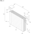
- FIGS. 4 and 5 illustrate a stack-type electrode assembly 1100 and a current collector 1200 according to a second embodiment of the present disclosure.
- the second embodiment of the present disclosure is characterized in that the positive electrode tabs 1132 and negative electrode tabs 1134 form a plurality of tab groups 1150, each formed in a row at different heights relative to the electrode assembly 1100.
- the positive electrode tabs 1132 and negative electrode tabs 1134 form a single tab group 1150 formed in a row at the same height relative to the stack-type electrode assembly 1100, whereas in the second embodiment, the positive electrode tabs 1132 and negative electrode tabs 1134 are divided into several tab groups 1150 of different heights.
- the number of foil tabs 1130 that can be welded to the current collector 1200 may be increased if the number of stacked unit cells is increased to increase the thickness of the stack-type electrode assembly 1100.
- the number of weldable foil tabs 1130 on the current collector 1200 can be understood to include not only the limit of foil tabs 1130 that are physically non-weldable, but also practical difficulties in welding, such as difficulty in welding due to limited welding space, or difficulty in obtaining a uniform welding quality.
- the second embodiment of the present disclosure is designed to improve several aspects of welding quality and welding management by dividing the plurality of positive electrode tabs 1132 and negative electrode tabs 1134 into several tab groups 1150.
- the second embodiment can be broken down into the specific examples of FIG. 4 and 5 in terms of the manner or structure of forming the tab groups 1150.
- the illustrated second embodiment exemplifies forming the tab group 1150 into two, it is of course possible to further subdivide the tab group 1150 into three or more.
- a single tab group 1150 is made up of the foil tabs 1130 of the unit cells provided in succession.
- the positive electrode current collector 1210 and negative electrode current collector 1220 can each have a number of branch current collectors 1230 corresponding to the plurality of tab groups 1150.
- a branch current collector 1230 refers to a partial current collector that is branched off from a single current collector as a stem, with each branch current collector 1230 having a different length corresponding to an up or down arrangement of the tab groups 1150 and arranged side-by-side along the height direction H of the stack-type electrode assembly 1100.
- the branched branch current collectors 1230 further facilitate welding operations for each tab group 1150.
- the positive electrode tabs 1132 and negative electrode tabs 1134 arranged in a zigzag pattern at different heights with respect to the electrode assembly 1100 form a single tab group 1150 per height. That is, the positive electrode tabs 1132 and negative electrode tabs 1134 of the same height are arranged while skipping a certain number of unit cells to form a single tab group 1150.
- the positive electrode tabs 1132 and negative electrode tabs 1134 are arranged in a zigzag pattern, skipping a single unit cell after another along the stacking direction of the unit cells.
- the distance between the positive electrode tabs 1132 and the negative electrode tabs 1134 may be as wide as the spacing of the skipped unit cells, which is advantageous for maintaining and improving the welding quality by securing more welding space on the current collector 1200 as the distance between the electrode tabs increases.
- the positive electrode current collector 1210 and negative electrode current collector 1220 each have a number of branch current collectors 1230 corresponding to the plurality of tab groups 1150, and in the embodiment of FIG. 5 , the branch current collectors 1230 are arranged side-by-side along the thickness direction T of the stack-type electrode assembly 1100 with different heights depending on the height of the corresponding tab group 1150. This is because the width of each tab group 1150 of different heights is approximately equal to the thickness of the stack-type electrode assembly 1100, and it is advantageous from a design perspective to have the branch current collectors 1230 arranged in a form that is bent away from each other.
- the present disclosure may provide a prismatic secondary battery 10 including the electrode assembly 1000 according to the first embodiment or the second embodiment, and an example of such a prismatic secondary battery 10 is shown in FIG. 6 .
- the prismatic secondary battery 10 includes a case 100 having at least one surface forming an open surface, and the aforementioned electrode assembly 1000 is stored within the case 100 through the open surface of the case 100.
- a cap plate 200 coupled to the open surface of the case 100 to seal the case 100 has electrode terminals 210 having different polarities, positive electrode terminal 212 and negative electrode terminal 214, wherein positive electrode current collector 1210 and negative electrode current collector 1220 of the electrode assembly 1000 are electrically connected to the positive electrode terminal 212 and negative electrode terminal 214 of the cap plate 200, respectively.
- the case 100 is then filled with an electrolyte 300, which serves as a medium for ionic conduction between the positive electrode and negative electrode.
- the prismatic secondary battery 10 of FIG. 6 has an electrode assembly 1000 with a substantially increased capacity due to the shortened length of the foil tabs 1130, and is suitable for the recent development trend of larger capacity secondary batteries.
Landscapes
- Chemical & Material Sciences (AREA)
- Chemical Kinetics & Catalysis (AREA)
- Electrochemistry (AREA)
- General Chemical & Material Sciences (AREA)
- Connection Of Batteries Or Terminals (AREA)
- Secondary Cells (AREA)
Abstract
Description
- This application is a National Phase of International Application No.
PCT/KR2023/011809 filed on August 10, 2023 KR 10-2022-0100270, filed on August 11, 2022 - The present invention relates to a stack-type electrode assembly, and to a technique for improving the practical capacity of a stack-type electrode assembly by shortening the length of a foil tab of a stack-type electrode assembly, thereby reducing the area occupied by a non-coated part.
- Unlike primary batteries, secondary batteries can be recharged, and they have been heavily researched and developed in recent years due to their potential for miniaturization and large capacity. The demand for secondary batteries as an energy source is increasing rapidly due to the technological development and increasing demand for mobile devices, electric vehicles, and energy storage systems, which are emerging in response to the need for environmental protection.
- Secondary batteries are categorized into coin-type cells, cylindrical cells, prismatic cells, and pouch-type cells based on the shape of the cell case. In a secondary battery, an electrode assembly mounted inside the battery case is a charge and dischargeable power generator consisting of a laminated structure of electrodes and separators.
- Electrode assemblies can be roughly categorized into Jellyroll type, which is wound by interposing a separator between a positive electrode and negative electrode of an active material-coated sheet, Stack-type in which a plurality of positive electrodes and negative electrodes is sequentially stacked with a separator interposed therebetween, and Stack & Folding type in which stack-type unit cells are wound with a long separator film.
- Among the various types of electrode assemblies, the stack-type electrode assembly consists of a number of unit cells stacked in a stack structure, with separators placed between the positive electrodes and negative electrodes, and each unit cell is provided with its own foil tab, including a positive electrode tab and a negative electrode tab. The foil tabs are formed by performing a punching process on a non-coated part of the positive electrode and negative electrode, where an active material is not applied. These foil tabs serve as the entrance and exit for electrical connections to the electrode assembly, and a plurality of foil tabs are welded to a current collector and tied together as one.
- However, as the capacity of secondary batteries increases to medium and large sizes, the number of unit cells stacked in the stack-type electrode assembly also increases. As the number of stacked unit cells increases, the number of foil tabs increases accordingly. The more foil tabs there are, the more difficult it becomes to weld them to the current collector, and the foil tabs are made longer to facilitate easier welding.
- The lengthening of the foil tabs means an increase in the width of the non-coated part in both the positive electrode and negative electrode. As the non-coated part without the active material increase, the actual capacity based on an electrode assembly of the same size decreases.
- The background description provided herein is for the purpose of generally presenting context of the disclosure. Unless otherwise indicated herein, the materials described in this section are not prior art to the claims in this application and are not admitted to be prior art, or suggestions of the prior art, by inclusion in this section.
- The present disclosure provides a solution for effective welding of a plurality of foil tabs to a current collector without increasing the length of the foil tabs, in line with the trend towards medium and large capacities of secondary batteries.
- However, the technical problems to be solved by the present disclosure are not limited to the above-described problem, and other problems not mentioned can be clearly understood by those skilled in the art from the following description.
- The present disclosure provides an electrode assembly which may include a stack-type electrode assembly; a plurality of positive electrode tabs located at a first end of the stack-type electrode assembly in a width direction; and a plurality of negative electrode tabs located at a second end of the stack-type electrode assembly in the width direction; and a positive electrode current collector and a negative electrode current collector electrically connected to the plurality of positive electrode tabs and to the plurality of negative electrode tabs, respectively, wherein: an end of each of the plurality of positive electrode tabs and an end of each of the plurality of negative electrode tabs are individually bonded to the positive electrode current collector and to the negative electrode current collector, respectively.
- An end of each of the positive electrode tabs and an end of each of the negative electrode tabs may include a bending portion, and the bending portion of each of the positive electrode tabs and the bending portion of each of the negative electrode tabs may be individually bonded to the positive electrode current collector and the negative electrode current collector, respectively.
- Here, each bending portion of the positive electrode tabs and each bending portion of the negative electrode tabs may be directly bonded to a facing surface of the positive electrode current collector and a facing surface of the negative electrode current collector, respectively.
- In an exemplary embodiment of the present disclosure, the positive electrode tabs may be arranged in a row at a substantially equal height with respect to the stack-type electrode assembly; and the negative electrode tabs may be arranged in a row at a substantially equal height with respect to the stack-type electrode assembly.
- In an exemplary embodiment of the present invention, the positive electrode tabs may form a plurality of positive tab groups, each positive tab group may be arranged in a row at a different height with respect to the stack-type electrode assembly; and the negative electrode tabs may form a plurality of negative tab groups, each negative tab group may be arranged in a row at a different height with respect to the stack-type electrode assembly.
- For example, the stack-type electrode assembly may include a plurality of unit cells arranged in a thickness direction; each positive tab group of the plurality of positive tab groups may comprise the positive electrode tabs of a plurality of adjacent unit cells of the stack-type electrode assembly; and each negative tab group of the plurality of negative tab groups may comprise the negative electrode tabs of a plurality of adjacent unit cells of the stack-type electrode assembly.
- In addition, the positive electrode current collector may include a plurality of positive branch current collectors, each positive branch current collector may correspond to one of the positive tab groups in the plurality of positive tab groups; and the negative electrode current collector may include a plurality of negative branch current collectors, each negative branch current collector may correspond to one of the negative tab groups in the plurality of negative tab groups.
- In certain embodiments, the plurality of positive branch current collectors may be arranged in parallel with respect to the thickness direction of the stack-type electrode assembly, each of the positive branch current collectors may have extend in a different height according to a height of one of the positive tab groups in the plurality of positive tab groups; and the plurality of negative branch current collectors may be arranged in parallel with respect to the thickness direction of the stack-type electrode assembly, each of the negative branch current collectors may extend in a different height according to a height of one of the negative tab groups in the plurality of negative tab groups.
- In certain cases, each positive tab group of the plurality of positive tab groups may comprise at least one non-contiguous pair of positive electrode tabs; and each negative tab group of the plurality of negative tab groups may comprise at least one non-contiguous pair of negative electrode tabs.
- In certain cases, the positive electrode tabs of adjacent unit cells of the stack-type electrode assembly may be arranged in a row at a different height with respect to the stack-type electrode assembly; and the negative electrode tabs of adjacent unit cells of the stack-type electrode assembly may be arranged in a row at a different height with respect to the stack-type electrode assembly.
- In addition, each of the plurality of positive branch current collectors may include a first portion extending in the thickness direction of the stack-type electrode assembly, wherein the first portions of each of the plurality of positive branch current collectors may be arranged in parallel with respect to a height direction of the stack-type electrode assembly; each of the plurality of positive branch current collectors may include a second portion extending in the height direction of the stack-type electrode assembly according to a height of one of the positive tab groups in the plurality of plurality of positive tab groups; each of the plurality of negative branch current collectors may include a first portion extending in the thickness direction of the stack-type electrode assembly, wherein the first portions of each of the plurality of negative branch current collectors may be arranged in parallel with respect to the height direction of the stack-type electrode assembly; and each of the plurality of negative branch current collectors may include a second portion extending in the height direction of the stack-type electrode assembly according to a height of one of the negative tab groups in the plurality of plurality of negative tab groups.
- Meanwhile, the present disclosure may provide a prismatic secondary battery including: a case; an electrode assembly, such as those disclosed herein, stored inside the case; a cap plate coupled to the case, the cap plate including a positive terminal and a negative terminal, wherein the positive terminal and the negative terminal are electrically connected to the positive electrode current collector and the negative electrode current collector of the electrode assembly, respectively; and an electrolyte inside the case.
- A stack-type electrode assembly of the present disclosure with the aforementioned configuration not only resolves the issue of the lengthening of foil tabs that occurs when a plurality of foil tabs are tack-welded and then welded to the current collector, as in conventional methods, by individually bonding each positive and negative electrode tab to the positive electrode current collector and negative electrode current collector, but it also improves the electrical conductivity of the stack-type electrode assembly.
- In addition, in the stack-type electrode assembly according to the present disclosure, the positive tabs and negative tabs each have a bending portion at their ends, and these bending portions are individually bonded to the positive electrode current collector and negative electrode current collector. Through the bending portion, sufficient welding area at the ends of the foil tabs may be secured, thereby preventing issues such as the foil tabs from shorting in the current collector due to insufficient welding strength.
- However, the technical effects that can be obtained through this disclosure are not limited to those described above. Other effects not mentioned here will be clearly understood by those skilled in the art from the description detailed below.
- The following drawings accompanying this specification illustrate preferred exemplary embodiments of the present disclosure and are intended to serve as a further understanding of the technical ideas of the present disclosure in conjunction with the detailed description of the disclosure that follows, so the present disclosure is not to be construed as limited to what is shown in such drawings.
-
FIG. 1 is a drawing illustrating a stack-type electrode assembly configuring the electrode assembly of the present disclosure. -
FIG. 2 is a drawing illustrating the structure in which a current collector is coupled to the stack-type electrode assembly ofFIG. 1 . -
FIG. 3 is a drawing illustrating a cross-sectional view in which the stack-type electrode assembly ofFIG. 1 is bonded to a current collector. -
FIG. 4 is a drawing illustrating a stack-type electrode assembly and a current collector according to another exemplary embodiment of the present disclosure. -
FIG. 5 is a drawing illustrating a stack-type electrode assembly and a current collector according to another exemplary embodiment of the present disclosure. -
FIG. 6 is a drawing illustrating an example of a prismatic secondary battery including the electrode assembly according to the present disclosure. - The present disclosure may have various modifications and various examples, and specific examples are illustrated in the drawings and described in detail in the description.
- However, it should be understood that the present disclosure is not limited to specific embodiments, and includes all modifications, equivalents or alternatives within the spirit and technical scope of the present disclosure.
- The terms "comprise," "include" and "have" are used herein to designate the presence of characteristics, numbers, steps, actions, components or members described in the specification or a combination thereof, and it should be understood that the possibility of the presence or addition of one or more other characteristics, numbers, steps, actions, components, members or a combination thereof is not excluded in advance.
- In addition, when a part of a layer, a film, a region or a plate is disposed "on" another part, this includes not only a case in which one part is disposed "directly on" another part, but a case in which a third part is interposed there between. In contrast, when a part of a layer, a film, a region or a plate is disposed "under" another part, this includes not only a case in which one part is disposed "directly under" another part, but a case in which a third part is interposed there between. In addition, in this application, "on" may include not only a case of disposed on an upper part but also a case of disposed on a lower part.
- The present disclosure provides an electrode assembly that includes a stack-type electrode assembly, and a positive electrode current collector and a negative electrode current collector.
- The stack-type electrode assembly is a plurality of unit cells stacked in a stack structure with a separator interposed between the positive electrode and negative electrode, with a plurality of positive electrode tabs and a plurality of negative electrode tabs formed at each end in the width direction. That is, the positive electrode tabs and negative electrode tabs are separated from each other on the sides of the stack-type electrode assembly.
- The positive electrode current collector and the negative electrode current collector are each a component of conductive material to which a plurality of positive electrode tabs and a plurality of negative electrode tabs are electrically connected. By having both a plurality of positive electrode tabs and a plurality of negative electrode tabs connected to the positive electrode current collector and the negative electrode current collector, respectively, the stack-type electrode assembly can be stored in the case of a prismatic secondary battery and wiring to the positive and negative electrode terminals is facilitated.
- In the present disclosure, the ends of the positive electrode tabs and negative electrode tabs are individually bonded to the positive electrode current collector and negative electrode current collector, respectively. As each positive electrode tab and negative electrode tab are independently bonded to the positive electrode current collector and negative electrode current collector, it not only solves the problem of the foil tabs lengthening due to tack welding of a plurality of foil tabs followed by re-welding to the current collector, as in conventional methods, but also enables performance improvements such as electrical conductivity performance in the stack-type electrode assembly, for example, increased rated current or reduced resistance, and the like.
- In addition, in the present disclosure, the positive electrode tabs and negative electrode tabs are each provided with a bending portions at their ends, and the bending portions of the positive electrode tabs and negative electrode tabs are individually bonded to the positive electrode current collectors and negative electrode current collectors, respectively. Through the bending portion, sufficient welding area at the ends of the foil tabs may be secured, thereby preventing issues such as the foil tabs from shorting in the current collector due to insufficient welding strength.
- Hereinafter, a detailed description will be given of specific embodiments of the secondary battery of the present disclosure with reference to the attached drawings. For reference, the relative positions specified in the directions of front and back, up and down, and left and right used in the following description are intended to aid in understanding the disclosure, and unless specially defined, are based on the directions shown in the drawings.
-
FIG. 1 is a drawing illustrating a stack-type electrode assembly 1100 according to a configuration of theelectrode assembly 1000 of the present disclosure. - The stack-
type electrode assembly 1100 is a plurality of unit cells stacked in sequence along one direction (thickness direction) with a separator interposed between the positive electrode and negative electrode, with a plurality ofpositive electrode tabs 1132 and a plurality ofnegative electrode tabs 1134 formed at each end of the width direction W. - The
positive electrode tabs 1132 andnegative electrode tabs 1134 are collectively referred to asfoil tabs 1130, and are formed by performing a punching process on anon-coated part 1120, which has no active material applied at the positive electrode and negative electrode, respectively. In other words, the illustrated stack-type electrode assembly 1100 has acoated part 1110 to which an active material is applied in the center part, andnon-coated parts 1120 are arranged on both sides of thecoated part 1110, and accordingly, thepositive electrode tabs 1132 andnegative electrode tabs 1134, which are punched on thenon-coated parts 1120, are of different polarity and separately arranged on both sides of the stack-type electrode assembly 1100. -
FIG. 2 is a drawing illustrating the structure in which thecurrent collector 1200 is coupled to the stack-type electrode assembly 1100 ofFIG. 1 , andFIG. 3 is a drawing illustrating a cross-section of the stack-type electrode assembly 1100 coupled to thecurrent collector 1200. Referring toFIG. 2 andFIG. 3 , the ends of thepositive electrode tabs 1132 andnegative electrode tabs 1134 are individually bonded to the positive electrodecurrent collector 1210 and the negative electrodecurrent collector 1220, respectively. - Conventionally, a plurality of foil tabs 1130 (positive electrode tabs and negative electrode tabs) provided on the stack-
type electrode assembly 1100 are tack welded to structurally and electrically interconnect and then re-welded to thecurrent collector 1200, thereby requiring that thefoil tabs 1130 be sufficiently long as the distance from the stack-type electrode assembly 1100 to thecurrent collector 1200 increases. - In comparison, the
electrode assembly 1000 of the present disclosure minimizes the distance from the stack-type electrode assembly 1100 to thecurrent collector 1200 as each of thepositive electrode tabs 1132 andnegative electrode tabs 1134 are independently welded to the positive electrodecurrent collector 1210 and negative electrodecurrent collector 1220, thereby increasing the substantial capacity based on the same size stack-type electrode assembly 1100 by shortening the length of thefoil tabs 1130 in which anon-coated part 1120 without an active material is processed. In addition, since theindividual foil tabs 1130 are welded directly to thecurrent collector 1200, a sufficient conduction area can be secured to carry a high current, and thus improved conduction performance, such as an increase in rated current and a decrease in resistance, can be obtained. - Also, referring to
FIGS. 1 through 3 , thepositive electrode tab 1132 and thenegative electrode tab 1134 each have abending portion 1140 at their ends, and the bendingportion 1140 of thepositive electrode tab 1132 and thenegative electrode tab 1134 are individually bonded to the positive electrodecurrent collector 1210 and the negative electrodecurrent collector 1220, respectively. Furthermore, each of the bendingportions 1140 of thepositive electrode tab 1132 and thenegative electrode tab 1134 can be directly bonded to a facing surface of the positive electrodecurrent collector 1210 and the negative electrodecurrent collector 1220, without a separate conducting medium. - As such, by forming the bending
portion 1140 at their respective ends, thepositive electrode tab 1132 andnegative electrode tab 1134 can provide sufficient welding area at the ends of thefoil tab 1130, thereby effectively preventing thefoil tab 1130 from shorting out from thecurrent collector 1200 due to insufficient welding strength. - And, in the first embodiment of the present disclosure, the
positive electrode tabs 1132 andnegative electrode tabs 1134 may be formed in a row at the same height relative to the stack-type electrode assembly 1100. Correspondingly, the positive electrodecurrent collector 1210 and the negative electrodecurrent collector 1220 have a width approximately corresponding to the thickness of the stack-type electrode assembly 1100, and therespective bending portions 1140 of thepositive electrode tab 1132 and thenegative electrode tab 1134 are welded in line to the positive electrodecurrent collector 1210 and the negative electrodecurrent collector 1220, respectively. -
FIGS. 4 and5 illustrate a stack-type electrode assembly 1100 and acurrent collector 1200 according to a second embodiment of the present disclosure. The second embodiment of the present disclosure is characterized in that thepositive electrode tabs 1132 andnegative electrode tabs 1134 form a plurality oftab groups 1150, each formed in a row at different heights relative to theelectrode assembly 1100. In other words, in the first embodiment described above, thepositive electrode tabs 1132 andnegative electrode tabs 1134 form asingle tab group 1150 formed in a row at the same height relative to the stack-type electrode assembly 1100, whereas in the second embodiment, thepositive electrode tabs 1132 andnegative electrode tabs 1134 are divided intoseveral tab groups 1150 of different heights. - In the first embodiment, where both the plurality of
positive electrode tabs 1132 andnegative electrode tabs 1134 are welded in line with respect to thecurrent collector 1200, the number offoil tabs 1130 that can be welded to thecurrent collector 1200 may be increased if the number of stacked unit cells is increased to increase the thickness of the stack-type electrode assembly 1100. Here, the number ofweldable foil tabs 1130 on thecurrent collector 1200 can be understood to include not only the limit offoil tabs 1130 that are physically non-weldable, but also practical difficulties in welding, such as difficulty in welding due to limited welding space, or difficulty in obtaining a uniform welding quality. - The second embodiment of the present disclosure is designed to improve several aspects of welding quality and welding management by dividing the plurality of
positive electrode tabs 1132 andnegative electrode tabs 1134 intoseveral tab groups 1150. The second embodiment can be broken down into the specific examples ofFIG. 4 and5 in terms of the manner or structure of forming the tab groups 1150. Here, while the illustrated second embodiment exemplifies forming thetab group 1150 into two, it is of course possible to further subdivide thetab group 1150 into three or more. - In the second embodiment shown in
FIG. 4 , thepositive electrode tabs 1132 andnegative electrode tabs 1134 of adjacent unit cells each form asingle tab group 1150. In other words, asingle tab group 1150 is made up of thefoil tabs 1130 of the unit cells provided in succession. - Correspondingly, the positive electrode
current collector 1210 and negative electrodecurrent collector 1220 can each have a number of branchcurrent collectors 1230 corresponding to the plurality oftab groups 1150. Abranch current collector 1230 refers to a partial current collector that is branched off from a single current collector as a stem, with each branchcurrent collector 1230 having a different length corresponding to an up or down arrangement of thetab groups 1150 and arranged side-by-side along the height direction H of the stack-type electrode assembly 1100. The branched branchcurrent collectors 1230 further facilitate welding operations for eachtab group 1150. - And, in the second embodiment shown in
FIG. 5 , thepositive electrode tabs 1132 andnegative electrode tabs 1134 arranged in a zigzag pattern at different heights with respect to theelectrode assembly 1100 form asingle tab group 1150 per height. That is, thepositive electrode tabs 1132 andnegative electrode tabs 1134 of the same height are arranged while skipping a certain number of unit cells to form asingle tab group 1150. InFIG. 5 , thepositive electrode tabs 1132 andnegative electrode tabs 1134 are arranged in a zigzag pattern, skipping a single unit cell after another along the stacking direction of the unit cells. - In a
single tab group 1150, the distance between thepositive electrode tabs 1132 and thenegative electrode tabs 1134 may be as wide as the spacing of the skipped unit cells, which is advantageous for maintaining and improving the welding quality by securing more welding space on thecurrent collector 1200 as the distance between the electrode tabs increases. - In addition, the positive electrode
current collector 1210 and negative electrodecurrent collector 1220 each have a number of branchcurrent collectors 1230 corresponding to the plurality oftab groups 1150, and in the embodiment ofFIG. 5 , the branchcurrent collectors 1230 are arranged side-by-side along the thickness direction T of the stack-type electrode assembly 1100 with different heights depending on the height of thecorresponding tab group 1150. This is because the width of eachtab group 1150 of different heights is approximately equal to the thickness of the stack-type electrode assembly 1100, and it is advantageous from a design perspective to have the branchcurrent collectors 1230 arranged in a form that is bent away from each other. - Meanwhile, the present disclosure may provide a prismatic secondary battery 10 including the
electrode assembly 1000 according to the first embodiment or the second embodiment, and an example of such a prismatic secondary battery 10 is shown inFIG. 6 . - Referring to
FIG. 6 , the prismatic secondary battery 10 includes acase 100 having at least one surface forming an open surface, and theaforementioned electrode assembly 1000 is stored within thecase 100 through the open surface of thecase 100. And, acap plate 200 coupled to the open surface of thecase 100 to seal thecase 100 has electrodeterminals 210 having different polarities,positive electrode terminal 212 andnegative electrode terminal 214, wherein positive electrodecurrent collector 1210 and negative electrodecurrent collector 1220 of theelectrode assembly 1000 are electrically connected to thepositive electrode terminal 212 andnegative electrode terminal 214 of thecap plate 200, respectively. Thecase 100 is then filled with anelectrolyte 300, which serves as a medium for ionic conduction between the positive electrode and negative electrode. - Thus, the prismatic secondary battery 10 of
FIG. 6 has anelectrode assembly 1000 with a substantially increased capacity due to the shortened length of thefoil tabs 1130, and is suitable for the recent development trend of larger capacity secondary batteries. - Various principles have been described in more detail above with reference to the drawings and embodiments. However, it is to be understood that the configurations shown in the drawings or embodiments described herein are only particular embodiments and do not represent all of the technical ideas of the disclosure, and that there may be various equivalents and modifications that may replace them at the time of filing the present application.
-
- 10: PRISMATIC SECONDARY BATTERY
- 100: CASE
- 200: CAP PLATE
- 210: ELECTRODE TERMINAL
- 212: POSITIVE ELECTRODE TERMINAL
- 214: NEGATIVE ELECTRODE TERMINAL
- 300: ELECTROLYTE
- 1000: ELECTRODE ASSEMBLY
- 1100: STACK-TYPE ELECTRODE ASSEMBLY
- 1110: COATED PART
- 1120: NON-COATED PART
- 1130: FOIL TAB
- 1132: POSITIVE ELECTRODE TAB
- 1134: NEGATIVE ELECTRODE TAB
- 1140: BENDING PORTION
- 1150: TAB GROUP
- 1200: CURRENT COLLECTOR
- 1210: POSITIVE ELECTRODE CURRENT COLLECTOR
- 1220: NEGATIVE ELECTRODE CURRENT COLLECTOR
- 1230: BRANCH CURRENT COLLECTOR
- W: WIDTH DIRECTION
- H: HEIGHT DIRECTION
- T: THICKNESS DIRECTION
Claims (13)
- An electrode assembly comprising:a stack-type electrode assembly;a plurality of positive electrode tabs located at a first end of the stack-type electrode assembly in a width direction; anda plurality of negative electrode tabs located at a second end of the stack-type electrode assembly in the width direction; anda positive electrode current collector and a negative electrode current collector electrically connected to the plurality of positive electrode tabs and to the plurality of negative electrode tabs, respectively, wherein:
an end of each of the plurality of positive electrode tabs and an end of each of the plurality of negative electrode tabs are individually bonded to the positive electrode current collector and to the negative electrode current collector, respectively. - The electrode assembly of claim 1, wherein:the end of each of the positive electrode tabs and the end of each of the negative electrode tabs include a bending portion, andthe bending portion of each of the positive electrode tabs and the bending portion of each of the negative electrode tabs are individually bonded to the positive electrode current collector and the negative electrode current collector, respectively.
- The electrode assembly of claim 2, wherein:
each bending portion of the positive electrode tabs and each bending portion of the negative electrode tabs is directly bonded to a facing surface of the positive electrode current collector and a facing surface of the negative electrode current collector, respectively. - The electrode assembly of claim 2, wherein:the positive electrode tabs are arranged in a row at a substantially equal height with respect to the stack-type electrode assembly; andthe negative electrode tabs are arranged in a row at a substantially equal height with respect to the stack-type electrode assembly.
- The electrode assembly of claim 2, wherein:the positive electrode tabs form a plurality of positive tab groups, each positive tab group arranged in a row at a different height with respect to the stack-type electrode assembly; andthe negative electrode tabs form a plurality of negative tab groups, each negative tab group arranged in a row at a different height with respect to the stack-type electrode assembly.
- The electrode assembly of claim 5, wherein:the stack-type electrode assembly includes a plurality of unit cells arranged in a thickness direction;each positive tab group of the plurality of positive tab groups comprises the positive electrode tabs of a plurality of adjacent unit cells of the stack-type electrode assembly; andeach negative tab group of the plurality of negative tab groups comprises the negative electrode tabs of a plurality of adjacent unit cells of the stack-type electrode assembly.
- The electrode assembly of claim 6, wherein:the positive electrode current collector includes a plurality of positive branch current collectors, each positive branch current collector corresponding to one of the positive tab groups in the plurality of positive tab groups; andthe negative electrode current collector includes a plurality of negative branch current collectors, each negative branch current collector corresponding to one of the negative tab groups in the plurality of negative tab groups.
- The electrode assembly of claim 7, wherein:the plurality of positive branch current collectors are arranged in parallel with respect to the thickness direction of the stack-type electrode assembly, each of the positive branch current collectors extending in a different height according to a height of one of the positive tab groups in the plurality of positive tab groups; andthe plurality of negative branch current collectors are arranged in parallel with respect to the thickness direction of the stack-type electrode assembly, each of the negative branch current collectors extending in a different height according to a height of one of the negative tab groups in the plurality of negative tab groups.
- The electrode assembly of claim 5, wherein:each positive tab group of the plurality of positive tab groups comprises at least one non-contiguous pair of positive electrode tabs; andeach negative tab group of the plurality of negative tab groups comprises at least one non-contiguous pair of negative electrode tabs.
- The electrode assembly of claim 9, wherein:the positive electrode tabs of adjacent unit cells of the stack-type electrode assembly are arranged in a row at a different height with respect to the stack-type electrode assembly; andthe negative electrode tabs of adjacent unit cells of the stack-type electrode assembly are arranged in a row at a different height with respect to the stack-type electrode assembly.
- The electrode assembly of claim 9, wherein:the positive electrode current collector includes a plurality of positive branch current collectors, each positive branch current collector corresponding to one of the positive tab groups in the plurality of positive tab groups; andthe negative electrode current collector includes a plurality of negative branch current collectors, each negative branch current collector corresponding to one of the negative tab groups in the plurality of negative tab groups.
- The electrode assembly of claim 11, wherein:each of the plurality of positive branch current collectors includes a first portion extending in the thickness direction of the stack-type electrode assembly, wherein the first portions of each of the plurality of positive branch current collectors are arranged in parallel with respect to a height direction of the stack-type electrode assembly;each of the plurality of positive branch current collectors includes a second portion extending in the height direction of the stack-type electrode assembly according to a height of one of the positive tab groups in the plurality of plurality of positive tab groups;each of the plurality of negative branch current collectors includes a first portion extending in the thickness direction of the stack-type electrode assembly, wherein the first portions of each of the plurality of negative branch current collectors are arranged in parallel with respect to the height direction of the stack-type electrode assembly; andeach of the plurality of negative branch current collectors includes a second portion extending in the height direction of the stack-type electrode assembly according to a height of one of the negative tab groups in the plurality of plurality of negative tab groups.
- A prismatic secondary battery comprising:a case;an electrode assembly according to claim 1 stored inside the case;a cap plate coupled to the case, the cap plate including a positive terminal and a negative terminal, wherein the positive terminal and the negative terminal are electrically connected to the positive electrode current collector and the negative electrode current collector of the electrode assembly, respectively; andan electrolyte inside the case.
Applications Claiming Priority (2)
| Application Number | Priority Date | Filing Date | Title |
|---|---|---|---|
| KR1020220100270A KR20240022061A (en) | 2022-08-11 | 2022-08-11 | Stack type electrode assembly having improved cell capacity |
| PCT/KR2023/011809 WO2024035141A1 (en) | 2022-08-11 | 2023-08-10 | Stack-type electrode assembly with improved cell capacity |
Publications (2)
| Publication Number | Publication Date |
|---|---|
| EP4429013A1 true EP4429013A1 (en) | 2024-09-11 |
| EP4429013A4 EP4429013A4 (en) | 2025-08-20 |
Family
ID=89852111
Family Applications (1)
| Application Number | Title | Priority Date | Filing Date |
|---|---|---|---|
| EP23853010.9A Pending EP4429013A4 (en) | 2022-08-11 | 2023-08-10 | Stacked electrode arrangement with improved cell capacity |
Country Status (6)
| Country | Link |
|---|---|
| US (1) | US20250087802A1 (en) |
| EP (1) | EP4429013A4 (en) |
| JP (1) | JP2024543682A (en) |
| KR (1) | KR20240022061A (en) |
| CN (1) | CN118451600A (en) |
| WO (1) | WO2024035141A1 (en) |
Families Citing this family (1)
| Publication number | Priority date | Publication date | Assignee | Title |
|---|---|---|---|---|
| CN119560738A (en) * | 2024-12-04 | 2025-03-04 | 金龙羽新能源(深圳)有限公司 | A battery cell, a battery and an electric device |
Family Cites Families (20)
| Publication number | Priority date | Publication date | Assignee | Title |
|---|---|---|---|---|
| JPS60181859U (en) * | 1984-05-15 | 1985-12-03 | 三洋電機株式会社 | square battery |
| JPH09147830A (en) * | 1995-11-24 | 1997-06-06 | Sony Corp | Battery and its electrode structure |
| JP2001256954A (en) | 2000-03-10 | 2001-09-21 | Sony Corp | Power storage device |
| JP3912574B2 (en) * | 2000-12-04 | 2007-05-09 | 株式会社ユアサ開発 | Sealed battery |
| US7592097B2 (en) * | 2004-04-26 | 2009-09-22 | Greatbatch Ltd. | Electrochemical cell designs with anode plates and connections which facilitate heat dissipation |
| JP5050313B2 (en) * | 2004-12-14 | 2012-10-17 | トヨタ自動車株式会社 | Battery and battery manufacturing method |
| JP4284341B2 (en) * | 2006-07-25 | 2009-06-24 | 株式会社東芝 | Non-aqueous electrolyte battery, automobile, assist bicycle, motorcycle, rechargeable vacuum cleaner and battery pack |
| TW200919807A (en) * | 2007-09-06 | 2009-05-01 | Sanyo Electric Co | Stact type battery |
| KR20140069702A (en) * | 2012-11-29 | 2014-06-10 | 주식회사 엘지화학 | Battery cell electrode lead, battery cell connecting structure, method and battery pack having the same |
| KR101675617B1 (en) * | 2013-02-15 | 2016-11-11 | 주식회사 엘지화학 | Method of stacking battery as bending electrode tabs |
| JP2015092457A (en) * | 2013-09-30 | 2015-05-14 | 住友電気工業株式会社 | Square storage device and method for manufacturing the same |
| KR102379562B1 (en) * | 2015-02-25 | 2022-03-28 | 삼성에스디아이 주식회사 | Battery pack |
| JP6593304B2 (en) * | 2016-11-07 | 2019-10-23 | トヨタ自動車株式会社 | Electric storage device and method for manufacturing electric storage device |
| EP3613093B1 (en) * | 2017-04-20 | 2026-03-04 | A123 Systems LLC | Battery tab configuration |
| JP6696487B2 (en) * | 2017-08-29 | 2020-05-20 | トヨタ自動車株式会社 | Power storage device |
| KR102571487B1 (en) * | 2017-08-31 | 2023-08-28 | 삼성에스디아이 주식회사 | Secondary Battery And Assembling Method thereof |
| WO2019187043A1 (en) * | 2018-03-30 | 2019-10-03 | 株式会社エンビジョンAescジャパン | Battery module, and method for manufacturing battery module |
| JP7615123B2 (en) * | 2020-03-27 | 2025-01-16 | 三洋電機株式会社 | Prismatic secondary battery and its manufacturing method |
| KR102461833B1 (en) * | 2020-12-09 | 2022-11-01 | 에스케이온 주식회사 | Battery module |
| CN217086650U (en) * | 2021-09-30 | 2022-07-29 | 蜂巢能源科技有限公司 | Laminated battery |
-
2022
- 2022-08-11 KR KR1020220100270A patent/KR20240022061A/en active Pending
-
2023
- 2023-08-10 CN CN202380015350.2A patent/CN118451600A/en active Pending
- 2023-08-10 WO PCT/KR2023/011809 patent/WO2024035141A1/en not_active Ceased
- 2023-08-10 JP JP2024535297A patent/JP2024543682A/en active Pending
- 2023-08-10 EP EP23853010.9A patent/EP4429013A4/en active Pending
- 2023-08-10 US US18/721,644 patent/US20250087802A1/en active Pending
Also Published As
| Publication number | Publication date |
|---|---|
| US20250087802A1 (en) | 2025-03-13 |
| KR20240022061A (en) | 2024-02-20 |
| JP2024543682A (en) | 2024-11-21 |
| EP4429013A4 (en) | 2025-08-20 |
| CN118451600A (en) | 2024-08-06 |
| WO2024035141A1 (en) | 2024-02-15 |
Similar Documents
| Publication | Publication Date | Title |
|---|---|---|
| US20250025957A1 (en) | Electrode Having Improved Electrode Tab Welding Characteristics and Secondary Battery Comprising the Same | |
| US11923564B2 (en) | Method for producing battery module | |
| KR100590006B1 (en) | Secondary Battery and Electrode Assembly Used in the Same | |
| KR100599749B1 (en) | Secondary Battery and Electrode Assembly Used in the Same | |
| CN103918106B (en) | Method with the internuncial electrode assemblie of excellent electrode tab, the battery unit including electrode assemblie and device and manufacture electrode assemblie | |
| KR100866767B1 (en) | Secondary battery safety member | |
| KR100599598B1 (en) | Secondary Battery, Electrode Assembly and Current Collecting Plate Used in the Same | |
| KR102883837B1 (en) | Electrode Assembly having Electrode Lead Combined with Multiple Metal Sheets and Method thereof | |
| EP2750241A1 (en) | Electrode assembly having stepped levels and battery cell, battery pack, and device comprising same | |
| KR20130132231A (en) | A stepwise electrode assembly, and a battery cell, battery pack and device comprising the same | |
| KR20130133640A (en) | A stepwise electrode assembly having corner of various shape and a battery cell, battery pack and device comprising the same | |
| KR20050121914A (en) | Secondary battery and electrodes assembly | |
| CN102714293A (en) | Battery cell module for a modular battery with interleaving separator | |
| KR20110025023A (en) | Electrode group and secondary battery using the same | |
| KR20190016353A (en) | Battery cell frame and battery module including the same | |
| CN113728506A (en) | Battery connecting device and method thereof | |
| KR100893225B1 (en) | Secondary battery with improved capacity and safety | |
| KR100599713B1 (en) | Secondary Battery and Electrode Assembly Used in the Same | |
| US11121399B2 (en) | Battery cell and method of manufacturing a battery cell | |
| EP4429013A1 (en) | Stack-type electrode assembly with improved cell capacity | |
| US20140023913A1 (en) | Prismatic secondary battery | |
| KR102601959B1 (en) | Electrode structure and prismatic battery including the same | |
| KR20200073191A (en) | Battery cell with bus bar | |
| KR20230058852A (en) | Battery Module and Battery Pack Having the same | |
| EP3358644A1 (en) | Battery cell and battery module |
Legal Events
| Date | Code | Title | Description |
|---|---|---|---|
| STAA | Information on the status of an ep patent application or granted ep patent |
Free format text: STATUS: THE INTERNATIONAL PUBLICATION HAS BEEN MADE |
|
| PUAI | Public reference made under article 153(3) epc to a published international application that has entered the european phase |
Free format text: ORIGINAL CODE: 0009012 |
|
| STAA | Information on the status of an ep patent application or granted ep patent |
Free format text: STATUS: REQUEST FOR EXAMINATION WAS MADE |
|
| 17P | Request for examination filed |
Effective date: 20240605 |
|
| AK | Designated contracting states |
Kind code of ref document: A1 Designated state(s): AL AT BE BG CH CY CZ DE DK EE ES FI FR GB GR HR HU IE IS IT LI LT LU LV MC ME MK MT NL NO PL PT RO RS SE SI SK SM TR |
|
| A4 | Supplementary search report drawn up and despatched |
Effective date: 20250722 |
|
| RIC1 | Information provided on ipc code assigned before grant |
Ipc: H01M 50/533 20210101AFI20250716BHEP Ipc: H01M 50/54 20210101ALI20250716BHEP Ipc: H01M 50/55 20210101ALI20250716BHEP Ipc: H01M 50/609 20210101ALI20250716BHEP Ipc: H01M 50/209 20210101ALI20250716BHEP |
|
| DAV | Request for validation of the european patent (deleted) | ||
| DAX | Request for extension of the european patent (deleted) |