EP4428972A1 - Plasma processing apparatus and lamination system for secondary battery comprising same - Google Patents
Plasma processing apparatus and lamination system for secondary battery comprising same Download PDFInfo
- Publication number
- EP4428972A1 EP4428972A1 EP23860918.4A EP23860918A EP4428972A1 EP 4428972 A1 EP4428972 A1 EP 4428972A1 EP 23860918 A EP23860918 A EP 23860918A EP 4428972 A1 EP4428972 A1 EP 4428972A1
- Authority
- EP
- European Patent Office
- Prior art keywords
- plasma processing
- processing apparatus
- contact portion
- separator
- secondary battery
- Prior art date
- Legal status (The legal status is an assumption and is not a legal conclusion. Google has not performed a legal analysis and makes no representation as to the accuracy of the status listed.)
- Pending
Links
Images


Classifications
-
- H—ELECTRICITY
- H01—ELECTRIC ELEMENTS
- H01M—PROCESSES OR MEANS, e.g. BATTERIES, FOR THE DIRECT CONVERSION OF CHEMICAL ENERGY INTO ELECTRICAL ENERGY
- H01M10/00—Secondary cells; Manufacture thereof
- H01M10/04—Construction or manufacture in general
-
- H—ELECTRICITY
- H01—ELECTRIC ELEMENTS
- H01M—PROCESSES OR MEANS, e.g. BATTERIES, FOR THE DIRECT CONVERSION OF CHEMICAL ENERGY INTO ELECTRICAL ENERGY
- H01M10/00—Secondary cells; Manufacture thereof
- H01M10/04—Construction or manufacture in general
- H01M10/0404—Machines for assembling batteries
-
- B—PERFORMING OPERATIONS; TRANSPORTING
- B01—PHYSICAL OR CHEMICAL PROCESSES OR APPARATUS IN GENERAL
- B01D—SEPARATION
- B01D67/00—Processes specially adapted for manufacturing semi-permeable membranes for separation processes or apparatus
- B01D67/0081—After-treatment of organic or inorganic membranes
- B01D67/009—After-treatment of organic or inorganic membranes with wave-energy, particle-radiation or plasma
-
- H—ELECTRICITY
- H01—ELECTRIC ELEMENTS
- H01M—PROCESSES OR MEANS, e.g. BATTERIES, FOR THE DIRECT CONVERSION OF CHEMICAL ENERGY INTO ELECTRICAL ENERGY
- H01M10/00—Secondary cells; Manufacture thereof
- H01M10/05—Accumulators with non-aqueous electrolyte
- H01M10/052—Li-accumulators
-
- H—ELECTRICITY
- H01—ELECTRIC ELEMENTS
- H01M—PROCESSES OR MEANS, e.g. BATTERIES, FOR THE DIRECT CONVERSION OF CHEMICAL ENERGY INTO ELECTRICAL ENERGY
- H01M10/00—Secondary cells; Manufacture thereof
- H01M10/05—Accumulators with non-aqueous electrolyte
- H01M10/058—Construction or manufacture
-
- H—ELECTRICITY
- H01—ELECTRIC ELEMENTS
- H01M—PROCESSES OR MEANS, e.g. BATTERIES, FOR THE DIRECT CONVERSION OF CHEMICAL ENERGY INTO ELECTRICAL ENERGY
- H01M50/00—Constructional details or processes of manufacture of the non-active parts of electrochemical cells other than fuel cells, e.g. hybrid cells
- H01M50/40—Separators; Membranes; Diaphragms; Spacing elements inside cells
- H01M50/403—Manufacturing processes of separators, membranes or diaphragms
-
- H—ELECTRICITY
- H01—ELECTRIC ELEMENTS
- H01M—PROCESSES OR MEANS, e.g. BATTERIES, FOR THE DIRECT CONVERSION OF CHEMICAL ENERGY INTO ELECTRICAL ENERGY
- H01M50/00—Constructional details or processes of manufacture of the non-active parts of electrochemical cells other than fuel cells, e.g. hybrid cells
- H01M50/40—Separators; Membranes; Diaphragms; Spacing elements inside cells
- H01M50/46—Separators, membranes or diaphragms characterised by their combination with electrodes
-
- H—ELECTRICITY
- H05—ELECTRIC TECHNIQUES NOT OTHERWISE PROVIDED FOR
- H05H—PLASMA TECHNIQUE; PRODUCTION OF ACCELERATED ELECTRICALLY-CHARGED PARTICLES OR OF NEUTRONS; PRODUCTION OR ACCELERATION OF NEUTRAL MOLECULAR OR ATOMIC BEAMS
- H05H1/00—Generating plasma; Handling plasma
- H05H1/24—Generating plasma
- H05H1/2406—Generating plasma using dielectric barrier discharges, i.e. with a dielectric interposed between the electrodes
- H05H1/2431—Generating plasma using dielectric barrier discharges, i.e. with a dielectric interposed between the electrodes using cylindrical electrodes, e.g. rotary drums
-
- H—ELECTRICITY
- H05—ELECTRIC TECHNIQUES NOT OTHERWISE PROVIDED FOR
- H05H—PLASMA TECHNIQUE; PRODUCTION OF ACCELERATED ELECTRICALLY-CHARGED PARTICLES OR OF NEUTRONS; PRODUCTION OR ACCELERATION OF NEUTRAL MOLECULAR OR ATOMIC BEAMS
- H05H1/00—Generating plasma; Handling plasma
- H05H1/24—Generating plasma
- H05H1/47—Generating plasma using corona discharges
- H05H1/473—Cylindrical electrodes, e.g. rotary drums
-
- Y—GENERAL TAGGING OF NEW TECHNOLOGICAL DEVELOPMENTS; GENERAL TAGGING OF CROSS-SECTIONAL TECHNOLOGIES SPANNING OVER SEVERAL SECTIONS OF THE IPC; TECHNICAL SUBJECTS COVERED BY FORMER USPC CROSS-REFERENCE ART COLLECTIONS [XRACs] AND DIGESTS
- Y02—TECHNOLOGIES OR APPLICATIONS FOR MITIGATION OR ADAPTATION AGAINST CLIMATE CHANGE
- Y02E—REDUCTION OF GREENHOUSE GAS [GHG] EMISSIONS, RELATED TO ENERGY GENERATION, TRANSMISSION OR DISTRIBUTION
- Y02E60/00—Enabling technologies; Technologies with a potential or indirect contribution to GHG emissions mitigation
- Y02E60/10—Energy storage using batteries
-
- Y—GENERAL TAGGING OF NEW TECHNOLOGICAL DEVELOPMENTS; GENERAL TAGGING OF CROSS-SECTIONAL TECHNOLOGIES SPANNING OVER SEVERAL SECTIONS OF THE IPC; TECHNICAL SUBJECTS COVERED BY FORMER USPC CROSS-REFERENCE ART COLLECTIONS [XRACs] AND DIGESTS
- Y02—TECHNOLOGIES OR APPLICATIONS FOR MITIGATION OR ADAPTATION AGAINST CLIMATE CHANGE
- Y02P—CLIMATE CHANGE MITIGATION TECHNOLOGIES IN THE PRODUCTION OR PROCESSING OF GOODS
- Y02P70/00—Climate change mitigation technologies in the production process for final industrial or consumer products
- Y02P70/50—Manufacturing or production processes characterised by the final manufactured product
Definitions
- the present disclosure relates to a plasma processing apparatus and a lamination system for a secondary battery including the same, and more particularly, to a plasma processing apparatus for improving wettability by adjusting an adhesive force between a separator and an electrode and a lamination system for a secondary battery including the plasma processing apparatus.
- secondary batteries refer to batteries that may be charged and discharged, unlike primary batteries that may not be charged. Secondary batteries are widely used in the field of advanced electronic devices such as phones, laptop computers, and camcorders.
- Secondary batteries are classified into cylindrical secondary batteries in which an electrode assembly is placed in a metal can, pouch-type secondary batteries in which an electrode assembly is placed in a pouch, and prismatic secondary batteries.
- a pouch-type secondary battery includes an electrode assembly, an electrolyte, a pouch in which the electrode assembly and the electrolyte are accommodated.
- a positive electrode and a negative electrode are located with the separator therebetween, an electrode tab is attached to each of the positive electrode and the negative electrode, and an electrode lead is coupled to the electrode tab.
- a lamination process is performed to increase adhesion of the electrode assembly in which the electrode and the separator are stacked.
- the present disclosure is designed to solve the problems of the related art, and therefore the present disclosure is directed to providing a plasma processing apparatus for improving wettability of an electrolyte by ensuring that there is an area having a weak adhesive force between an electrode and a separator or not bonded in a unit cell used in secondary battery manufacturing, and a lamination system for a secondary battery including the plasma processing apparatus.
- the present disclosure is also directed to providing a plasma processing apparatus for minimizing lithium plating by guiding smooth discharge of gas of a unit cell, and a lamination system for a secondary battery including the plasma processing apparatus.
- a plasma processing apparatus of a unit cell for a secondary battery includes a discharge roller configured to transport a separator of the unit cell for a secondary battery and allowing a metal member to be placed therein, and a plasma processing member configured to generate plasma through a mutual reaction with the metal member and irradiate the plasma to a surface of the separator, wherein a pattern portion having a certain stepped portion is formed on an outer surface of the discharge roller.
- the pattern portion may include a contact portion closely in close contact with the separator when the separator is transported, and a non-contact portion having a height difference corresponding to a certain depth from the contact portion and spaced apart from the separator by a certain distance.
- an adhesive area may be formed on a surface of the separator located on the contact portion, and a non-adhesive area may be formed on a surface of the separator located on the non-contact portion.
- the pattern portion may include a connecting portion that connects the contact portion to the non-contact portion.
- the contact portion and the non-contact portion may be alternately arranged on the outer surface of the discharge roller.
- the contact portion and the non-contact portion may be provided in at least one of a longitudinal direction and a width direction of the discharge roller.
- the non-contact portion may be recessed to a certain depth from the outer surface of the discharge roller.
- a recess depth of the non-contact portion may be 2 mm.
- the pattern portion may include a plurality of patterns having different lengths or widths.
- the plurality of patterns may have different recess depths.
- the pattern portion may be provided in a mosaic shape.
- a lamination system for a secondary battery includes the plasma processing apparatus
- a plasma processing apparatus for improving wettability of an electrolyte by ensuring that there is an area having a weak adhesive force between an electrode and a separator or not bonded in a unit cell used in secondary battery manufacturing, and a lamination system for a secondary battery including the plasma processing apparatus.
- a plasma processing apparatus for minimizing lithium plating by guiding smooth discharge of gas of a unit cell, and a lamination system for a secondary battery including the plasma processing apparatus.
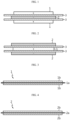
- FIGS. 1 and 2 are views illustrating a unit cell for a secondary battery according to an embodiment of the present disclosure.
- FIGS. 3 and 4 are views illustrating a positive electrode and a negative electrode applied to a unit cell for a secondary battery according to an embodiment of the present disclosure.
- a unit cell for a secondary battery includes a central electrode having a first polarity, a pair of separators 3 respectively laminated on both surfaces of the central electrode, and an upper electrode and a lower electrode respectively laminated on the pair of separators and having a second polarity opposite to the first polarity.
- a unit cell in which outermost electrodes have the same polarity is generally called a bi-cell.
- Such a bi-cell type unit cell may be divided into a positive electrode type bi-cell in which an upper electrode and a lower electrode are positive electrodes 1 and a central electrode is a negative electrode 2 as shown in FIG. 1 , and a negative electrode type bi-cell in which an upper electrode and a lower electrode are negative electrodes 2 and a central electrode is a positive electrode 1 as shown in FIG. 2 .
- a secondary battery configured by using such a bi-cell may have a structure in which a positive electrode type bi-cell and a negative electrode type bi-cell are alternately stacked with a separator therebetween.
- Such bi-cells may be stacked by using a simple stacking method, a stacking and folding method, etc.
- the positive electrode 1 applied to the unit cell for a secondary battery includes a positive electrode current collector 1a and a positive electrode active material 1b laminated on a surface of the positive electrode current collector 1a as shown in FIG. 3 .
- the positive electrode current collector 1a may be a foil formed of aluminum, nickel, or a combination thereof.
- the negative electrode 2 applied to the unit cell for a secondary battery includes a negative electrode current collector 2a and a negative electrode active material 2b laminated on a surface of the negative electrode current collector 2a as shown in FIG. 4 .
- the negative electrode current collector 2a may be a foil formed of stainless steel, nickel, copper, titanium, or an alloy thereof.
- the negative electrode active material 2b may be any of common negative electrode active materials available as a negative electrode of a secondary battery in the art, and examples of the negative electrode active material 2b may include, but are not limited to, carbon such as hard graphitized carbon or graphite-based carbon; metal composite oxides such as LixFe 2 O 3 (0 ⁇ x ⁇ 1), LixWO 2 (0 ⁇ x ⁇ 1), and SnxMe1-xMe'yOz (Me: Mn, Fe, Pb, Ge; Me': Al, B, P, Si, Group 1, 2, and 3 elements in the periodic table, halogen; 0 ⁇ x ⁇ 1; 1 ⁇ y ⁇ 3; 1 ⁇ z ⁇ 8); lithium metals; lithium alloys; silicon-based alloys; tin-based alloys; oxides such as SnO, SnO 2 , PbO, PbO 2 , Pb 2 O 3 , Pb 3 O 4 , Sb 2 O 3 , Sb 2
- the separator 3 located between the positive electrode 1 and the negative electrode 2 may include a porous coating layer formed on one surface or both surfaces of a porous polymer substrate.
- the porous polymer substrate used in the separator 3 is not particularly limited as long as it is a planar porous polymer substrate that is usually applied to a secondary battery.
- the porous polymer substrate may be in the form of a film or a nonwoven fabric.
- the porous coating layer is formed on one surface or both surfaces of the porous polymer substrate, inorganic particles are connected and fixed by a binder polymer for the porous coating layer, and pores in a micrometer size are formed in the porous coating layer due to an interstitial volume between the inorganic particles.
- the binder polymer for the porous coating layer is not particularly limited as long as it has an excellent bonding strength with the inorganic particles and is not easily dissolved by an electrolyte.
- an adhesive force is not uniformly formed but a patterned adhesive force is formed, at an interface between the positive electrode 1 and the separator 3 and/or an interface between the negative electrode 2 and the separator 3. That is, the interface between the electrodes 1, 2 and the separator 3 has a different adhesive force for each area so that the electrodes 1, 2 and the separator 3 are adhered with different strengths at various areas.
- a method of forming such a patterned adhesive force will be described in more detail with reference to the following drawings.
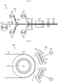
- FIG. 5 is a schematic view illustrating a lamination system for a secondary battery for manufacturing a unit cell for a secondary battery according to the present disclosure.
- a lamination system 10 for a secondary battery may include a central electrode supply roller 100, a plasma processing apparatus 200, an upper electrode supply roller 320, a lower electrode supply roller 330, a heater unit 400, a lamination roller 500, and cutter units 610, 620, 630, 640.
- the central electrode supply roller 100 may supply a central electrode E1 for unit cell manufacturing. To this end, the central electrode supply roller 100 is wound with the central electrode E1 in the form of a long fabric to supply the central electrode E1.
- the plasma processing apparatus 200 for increasing adhesion, electrolyte impregnation, and gas discharge of a unit cell, which is a basic unit, may supply separators S1, S2 to both surfaces of the central electrode E1 and perform plasma treatment on surfaces of the separators S1, S2, to increase an adhesive force with the electrodes E1, E2, E3 through surface modification of the separators S1, S2.
- the plasma processing apparatus 200 may include discharge rollers 220, 230 that transport the separators S1, S2 of the unit cell for a secondary battery and in which a metal member 240 is provided, and a plasma processing member 260 that generates plasma through a mutual reaction with the metal member 240 and irradiates the plasma to surfaces of the separators S1, S2.
- a pattern portion 250 (see FIGS. 7 to 9 ) having a certain stepped portion may be formed on outer surfaces of the discharge rollers 220, 230.
- patterned plasma treatment may be performed so that plasma treatment is performed on some areas of the surfaces of the separators S1, S2 and plasma treatment is not performed on the remaining areas. That is, the plasma processing apparatus 200 may activate a uniform and patterned adhesive force on the surfaces of the separators S1, S2 so that the electrodes E1, E2, E3 and the separators S1, S2 are pattern-adhered.
- the discharge rollers 220, 230 may include a first discharge roller 220 and a second discharge roller 230.
- the first discharge roller 220 for transporting one separator S1 may include the metal member 240 therein.
- the second discharge roller 230 for transporting the other separator S2 may include the metal member 240 therein.
- the plasma processing member 260 may be spaced apart from the separators S1, S2, and may generate plasma P through a mutual reaction with the metal member 240 and irradiate the plasma P to the surfaces of the separators S1, S2.
- the plasma processing member 260 may include a processing member body 261, an electrode piece 264, and a switch 265.
- the processing member body 261 may be spaced apart from each of the separators S1, S2, and may be provided in a width direction of the separators S1, S2.
- the processing member body 261 may be formed of a non-metallic material, and thus, may prevent resistance from occurring between the metal member 240 and the electrode piece 264. As a result, the plasma P may be stably generated between the metal member 240 and the processing member body 261.
- the processing member body 261 may be formed of ceramic among non-metallic materials.
- the ceramic is a non-metal inorganic material obtained through a heat treatment process, has heat resistance, high strength, corrosion resistance, and is particularly light, thereby increasing the efficiency of use.
- the electrode piece 264 may be a corona discharge electrode, and the plasma P may be stably generated between the metal member 240 and the processing member body 261 through the corona discharge electrode.
- the electrode piece 264 may include a plurality of unit electrode pieces, and the plurality of unit electrode pieces may be connected along the width direction of the separators S1, S2 on the processing member body 261 to form one electrode piece 264, and thus, may be compatibly used for separators having various widths.
- the plurality of unit electrode pieces may be spaced apart from each other along the width direction of the separators S1, S2 on the processing member body 261. Due to this feature, the plasma P may be partially generated between the metal member 240 and the processing member body 261 and as a result, a patterned adhesive force may be formed on the surfaces of the separators S1, S2.
- the plurality of unit electrode pieces may have the same length, width, and thickness or may be different from each other in at least one of a length, width, and thickness. Accordingly, adhesive forces of various patterns may be formed on the surfaces of the separators S1, S2.
- the processing member body 261 may have an insertion groove 263 that is formed long in the width direction of the separators S1, S2, and the electrode piece 264 may be inserted and fixed into the insertion groove 263. Accordingly, damage to the electrode piece 264 from an external object may be prevented and as a result, the plasma P may be stably generated.
- the switch 265 may supply power to the electrode piece 264.
- the switch 265 may easily adjust whether to use the electrode piece 264 by controlling power supplied to the electrode piece 264, thereby preventing unnecessary power waste.
- the plasma P may be generated as the metal member 240 and the electrode piece 264 correspond to each other, and an adhesive force is formed on the separators S 1, S2 as the plasma P is irradiated to the surfaces of the separators S 1, S2 between the metal member 240 and the electrode piece 264.
- the pattern portion 250 may be formed on a surface 221 of the discharge roller 220 and may be provided in a mosaic shape. Although not shown, the pattern portion 250 is also formed on a surface of the second discharge roller 230 that transports the other separator S2. In the following description, for convenience of explanation, the pattern portion 250 provided on the first discharge roller 220 corresponding to the one separator S 1 will be mainly described.
- the pattern portion 250 may include a contact portion 252 and a non-contact portion 254.
- the contact portion 252 may be provided on the surface of the discharge roller 220, and may be in close contact with the separator S 1 when the separator S 1 is transported. There is a height difference corresponding to a certain depth h between the non-contact portion 254 and the contact portion 252, and the non-contact portion 254 may be spaced apart from the separator S 1 by a certain distance.
- the non-contact portion 254 may be recessed to the certain depth h from the outer surface 221 of the discharge roller 220.
- a recess depth of the non-contact portion 254 may be about 2 mm.
- the contact portion 252 and the non-contact portion 254 may be alternately arranged on the discharge roller 220, specifically, on the outer surface of the first discharge roller 220, to form a certain pattern on the surface of the discharge roller 220.
- the certain pattern may be provided in various ways according to a preset design condition according to a shape or a size of the separator S1.
- the contact portion 252 and the non-contact portion 254 may be provided in at least one of a longitudinal direction and a width direction of the discharge roller 220.
- a plurality of contact portions 252 and a plurality of non-contact portions 254 may be provided.
- the plurality of contact portions 252 may be spaced apart from each other by a certain distance, and may have a preset separation distance.
- the plurality of non-contact portions 252 may be formed by etching from the outer surface 221 of the discharge roller 220, and may have a preset etch length, etch width, and etch depth. At least some of the plurality of non-contact portions 252 may have different etch lengths and etch widths.
- Various patterns may be formed on the surface 221 of the discharge roller 220 according to various arrangements or shapes of the contact portion 252 and the non-contact portion 254, and thus, may be applied to the separators S1 having various sizes, and adhesive forces of various patterns may be formed according to a required design, etc.
- the pattern portion 250 may include a connecting portion 256 that connects the contact portion 252 to the non-contact portion 254.
- the connecting portion 256 may guide the formation of an uneven pattern on the pattern portion 250 while connecting the contact portion 252 to the non-contact portion 254.
- the separator S1 transported over the first discharge roller 220 may be divided into an area in close contact with the pattern portion 250 and an area spaced apart from the pattern portion 250.
- the area of the separator S1 in close contact with the pattern portion 250 may be an area located on the contact portion 252, and the area of the separator S1 spaced apart from the pattern portion 250 may be an area located on the non-contact portion 254.
- the area of the separator S1 located on the contact portion 252 is in closer contact with the first discharge roller 220 than the area of the separator S1 located on the non-contact portion 254, when the plasma P is irradiated, the area of the separator S1 located on the contact portion 252 may have a smoother interaction with the metal member 240 to form an adhesive area with a high adhesion area.
- the area of the separator S1 located on the non-contact portion 254 is spaced apart from the surface of the first discharge roller 220, when the plasma P is irradiated, the area of the separator S 1 located on the non-contact portion 254 may have a weak interaction with the metal member 240 to form a non-adhesive area with a low adhesion area.
- an adhesive area A1 may be formed on a surface of the separator S1 located on the contact portion 252 and a non-adhesive area A2 may be formed on a surface of the separator located on the non-contact portion 254.
- the adhesive area A1 and the non-adhesive area A2 may be alternately arranged, and thus, may have a patterned adhesive force of a mosaic shape in which the adhesive area A1 and the non-adhesive area A2 are alternately formed.
- the plasma processing apparatus 200 there may be formed a mask having a patterned adhesive force as the adhesive area A1 and the non-adhesive area A2 are formed on the surfaces of the separators S1, S2, through the pattern portion 250 formed on the surfaces of the discharge rollers 220, 230.
- Bonding between materials may be divided into chemical adhesion and mechanical interlocking.
- the improvement of an adhesive force by plasma treatment as in the present disclosure is a result of the reinforcement of a chemical adhesive force.
- the chemical adhesion may be divided into electrostatic attraction, chemical absorption, and chemical bonding.
- the area A2 not treated with the plasma P has a relatively low adhesive force, which improves the impregnation of an electrolyte in the area.
- FIG. 10 is a view for describing a plasma processing apparatus according to another embodiment of the present disclosure.
- a plasma processing apparatus 205 according to the present embodiment is similar to the plasma processing apparatus 200 of the above embodiment, and thus, elements that are substantially the same or similar as those in the above embodiment will be not repeatedly described and a difference from the above embodiment will be mainly described.
- a pattern portion 290 may be formed to have a different length, width, separation distance, and etch depth according to a preset design of a unit cell.
- the pattern portion 290 may include a plurality of patterns having different lengths or widths.
- the plurality of patterns may be formed to have different recess depths.
- the plasma processing apparatus 200 forms a certain stepped portion having a mosaic shape on surfaces of the discharge rollers 220, 230, uniform distribution plasma treatment may be performed through a longitudinal direction and a width direction of the separators S1, S2 to perform uniform mosaic pattern corona treatment, thereby significantly increasing adhesion, electrolyte impregnation, and gas discharge of the unit cell that is a basic unit.
- the plasma processing apparatus 200 may significantly increase gas discharge as described above, lithium plating may be effectively prevented.
- the upper electrode supply roller 320 for supplying the upper electrode E2 in the form of a long fabric may supply the upper electrode E2 to the separators S1, S2 on which plasma treatment has been performed.
- the lower electrode supply roller 330 for supplying the lower electrode E3 in the form of a long fabric may face the upper electrode supply roller 320 and may supply the lower electrode E3 to the separators S1, S2 on which plasma treatment has been performed.
- the heater unit 400 for guiding adhesion of the separators S1, S2, the upper electrode E2, and the lower electrode E3 may heat the upper electrode E2 and the lower electrode E3 located on the separators S1, S2.
- the lamination roller 500 may apply pressure to the upper electrode E2 and the lower electrode E3 adhered to the separators S1, S2 heated through the heater unit 400 to compress between each electrode and each separator.
- the cutter units 610, 620, 630, 640 may cut each of the central electrode E1, the upper electrode E2, and the lower electrode E3 each in the supplied fabric form and the separators S1, S2 in a pre-determined manner.
- the cutter units 610, 620, 630, 640 may include a first cutter 610, a second cutter 620, a third cutter 630, and a fourth cutter 640.
- the first cutter 610 may cut the central electrode E1 to a certain size.
- the second cutter 620 may cut at least one of the upper electrode E2 and the separator S1, and the third cutter 630 may cut at least one of the lower electrode E3 and the separator S2.
- the fourth cutter 640 may cut each of the electrodes E1, E2, E3 and the separators S1, S2 so as to manufacture the unit cell for a secondary battery which is a basic unit.
- a process of manufacturing the unit cell for a secondary battery may further include inspecting and discharging a completely laminated unit cell for a secondary battery.
- the inspecting of the unit cell refers to inspecting whether there is a foreign material between the electrode and the separator and whether the unit cell is manufactured with an accurate size in a stacking process for manufacturing the unit cell.
- an adhesive force may not be uniformly formed but a patterned adhesive force may be formed, at an interface between the positive electrode 1 and the separator 3 and/or an interface between the negative electrode 2 and the separator 3. That is, the interface between the electrodes 1, 2 and the separator 3 has a different adhesive force for each area so that the electrodes 1, 2 and the separator 3 are adhered with different strengths at various areas.
- FIG. 11 is a view for describing an adhesive force measurement test through a plasma processing apparatus according to an embodiment of the present disclosure.
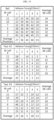
- FIGS. 12 to 15 are views for describing a result of the adhesive force measurement test of FIG. 11 .
- FIGS. 11 to 15 first, Reference (indicated by Ref. in FIGS. 12 and 15 ) corresponds to full corona treatment, and Test #2 and Test #3 correspond to mosaic corona treatment.
- FIG. 11 illustrates measurement of an adhesive force of a folding surface facing a negative electrode in Test #2 and Test #3 products. Adhesive force measurement positions are Positions 1 to 5 in the drawings, wherein a tap side corresponds to Position 1, central portions correspond to Position 2, Position 3, and Position 4, and a lower side corresponds to Position 5.
- a corona treated area that is, a mosaic corona treated area is shown in a rectangular box shape.
- Bi-cell numbers 2, 3, 6, 7, 10, 11 shown in FIG. 15 are numbers of positions in a cell according to bi-cell stacking.
- mosaic corona treatment is performed in a total of two areas including the tab side (Position 1) and lower side (Position 5), and in the case of Test #3, mosaic corona treatment is performed in a total of six areas including the tab side (Position 1), the lower side (Position 5), and the central portions (Positions 2, 4), between the central portion (Position 2) and the tab side (Position 1), and between the central portion (Position 4) and the lower side (Position 5).
- an adhesive force of a surface of a folding separator facing a negative electrode in a mosaic corona untreated area of Test #2 and Test #3 products is as low as about 5 gf.
- an adhesive force tends to be increased in Positions 2 and 4, that is, the central portions (Positions 2, 4) which are mosaic corona treated areas. It is found that an adhesive force is increased from about 5 gf to about 16 gf.
- the plasma processing apparatuses 200, 205 for improving wettability of an electrolyte by ensuring that there is an area having a weak adhesive force between an electrode and a separator or not bonded in a unit cell used in secondary battery manufacturing, and the lamination system 10 for a secondary battery including the plasma processing apparatuses 200, 205.
- the plasma processing apparatuses 200, 205 for minimizing lithium plating by guiding smooth discharge of gas of a unit cell, and the lamination system 10 for a secondary battery including the plasma processing apparatuses 200, 205.
Landscapes
- Engineering & Computer Science (AREA)
- Chemical & Material Sciences (AREA)
- Chemical Kinetics & Catalysis (AREA)
- Electrochemistry (AREA)
- General Chemical & Material Sciences (AREA)
- Manufacturing & Machinery (AREA)
- Physics & Mathematics (AREA)
- Plasma & Fusion (AREA)
- Spectroscopy & Molecular Physics (AREA)
- Inorganic Chemistry (AREA)
- Secondary Cells (AREA)
Abstract
Description
- The present disclosure relates to a plasma processing apparatus and a lamination system for a secondary battery including the same, and more particularly, to a plasma processing apparatus for improving wettability by adjusting an adhesive force between a separator and an electrode and a lamination system for a secondary battery including the plasma processing apparatus.
- The present application claims priority to
Korean Patent Application No. 10-2022-0111700 filed on September 2, 2022 - In general, secondary batteries refer to batteries that may be charged and discharged, unlike primary batteries that may not be charged. Secondary batteries are widely used in the field of advanced electronic devices such as phones, laptop computers, and camcorders.
- Secondary batteries are classified into cylindrical secondary batteries in which an electrode assembly is placed in a metal can, pouch-type secondary batteries in which an electrode assembly is placed in a pouch, and prismatic secondary batteries. A pouch-type secondary battery includes an electrode assembly, an electrolyte, a pouch in which the electrode assembly and the electrolyte are accommodated. In the electrode assembly, a positive electrode and a negative electrode are located with the separator therebetween, an electrode tab is attached to each of the positive electrode and the negative electrode, and an electrode lead is coupled to the electrode tab.
- In the pouch-type secondary battery, a lamination process is performed to increase adhesion of the electrode assembly in which the electrode and the separator are stacked.
- However, in a conventional polymer cell manufacturing process, because bi-cells are laminated at a constant temperature/pressure for better process efficiency, wettability at an interface between an electrode and a separator is lowered.
- That is, when an adhesive force at the interface between the electrode and the separator is constant and the electrode and the separator are completely uniformly adhered to each other as a whole, an electrolyte may not easily permeate between the electrode and the separator and thus, a secondary battery may not perform full performance.
- In particular, under the same process conditions, because the adhesive force at the interface between the positive electrode and the separator is stronger, wettability tends to be more lowered. For this reason, the performance of the secondary battery is degraded more seriously.
- Also, when the adhesive force at the interface between the electrode and the separator is uniformly high as above, gas generated in a formation process performed during a secondary battery manufacturing process may not be smoothly discharged. When the gas is not smoothly discharged smoothly, lithium plating may occur.
- The present disclosure is designed to solve the problems of the related art, and therefore the present disclosure is directed to providing a plasma processing apparatus for improving wettability of an electrolyte by ensuring that there is an area having a weak adhesive force between an electrode and a separator or not bonded in a unit cell used in secondary battery manufacturing, and a lamination system for a secondary battery including the plasma processing apparatus.
- The present disclosure is also directed to providing a plasma processing apparatus for minimizing lithium plating by guiding smooth discharge of gas of a unit cell, and a lamination system for a secondary battery including the plasma processing apparatus.
- However, the technical problems to be solved by the present disclosure are not limited thereto, and other unmentioned technical problems will be understood by one of ordinary skill in the art from the following description of the present disclosure.
- In one aspect of the present disclosure, a plasma processing apparatus of a unit cell for a secondary battery includes a discharge roller configured to transport a separator of the unit cell for a secondary battery and allowing a metal member to be placed therein, and a plasma processing member configured to generate plasma through a mutual reaction with the metal member and irradiate the plasma to a surface of the separator, wherein a pattern portion having a certain stepped portion is formed on an outer surface of the discharge roller.
- Preferably, the pattern portion may include a contact portion closely in close contact with the separator when the separator is transported, and a non-contact portion having a height difference corresponding to a certain depth from the contact portion and spaced apart from the separator by a certain distance.
- Preferably, when plasma of the plasma processing member is irradiated, an adhesive area may be formed on a surface of the separator located on the contact portion, and a non-adhesive area may be formed on a surface of the separator located on the non-contact portion.
- Preferably, the pattern portion may include a connecting portion that connects the contact portion to the non-contact portion.
- Preferably, the contact portion and the non-contact portion may be alternately arranged on the outer surface of the discharge roller.
- Preferably, the contact portion and the non-contact portion may be provided in at least one of a longitudinal direction and a width direction of the discharge roller.
- Preferably, the non-contact portion may be recessed to a certain depth from the outer surface of the discharge roller.
- Preferably, a recess depth of the non-contact portion may be 2 mm.
- Preferably, the pattern portion may include a plurality of patterns having different lengths or widths.
- Preferably, the plurality of patterns may have different recess depths.
- Preferably, the pattern portion may be provided in a mosaic shape.
- In another aspect of the present disclosure, a lamination system for a secondary battery includes the plasma processing apparatus
- According to various embodiments of the present disclosure, there may be provided a plasma processing apparatus for improving wettability of an electrolyte by ensuring that there is an area having a weak adhesive force between an electrode and a separator or not bonded in a unit cell used in secondary battery manufacturing, and a lamination system for a secondary battery including the plasma processing apparatus.
- Also, according to various embodiments of the present disclosure, there may be provided a plasma processing apparatus for minimizing lithium plating by guiding smooth discharge of gas of a unit cell, and a lamination system for a secondary battery including the plasma processing apparatus.
- In addition, various other additional effects may be achieved by various embodiments of the present disclosure. The present disclosure may have various other effects, which will be described in each embodiment, or descriptions of effects that may be easily inferred by one of ordinary skill in the art will be omitted.
- The accompanying drawings illustrate a preferred embodiment of the present disclosure and together with the foregoing disclosure, serve to provide further understanding of the technical features of the present disclosure, and thus, the present disclosure is not construed as being limited to the drawing.
-
FIGS. 1 and 2 are views illustrating a unit cell for a secondary battery according to an embodiment of the present disclosure. -
FIGS. 3 and 4 are views illustrating a positive electrode and a negative electrode applied to a unit cell for a secondary battery according to an embodiment of the present disclosure. -
FIG. 5 is a schematic view illustrating a lamination system for a secondary battery for manufacturing a unit cell for a secondary battery according to an embodiment of the present disclosure. -
FIG. 6 is a view illustrating a plasma processing apparatus of the lamination system for a secondary battery ofFIG. 5 . -
FIG. 7 is a schematic perspective view illustrating the plasma processing apparatus ofFIG. 6 . -
FIG. 8 is a schematic perspective view illustrating a state where a separator passes through the plasma processing apparatus ofFIG. 6 . -
FIG. 9 is a cross-sectional view illustrating a main portion of the plasma processing apparatus ofFIG. 8 . -
FIG. 10 is a view for describing a plasma processing apparatus according to another embodiment of the present disclosure. -
FIG. 11 is a view for describing an adhesive force measurement test through a plasma processing apparatus according to an embodiment of the present disclosure. -
FIGS. 12 to 15 are views for describing a result of the adhesive force measurement test ofFIG. 11 . - Hereinafter, preferred embodiments of the present disclosure will be described in detail with reference to the accompanying drawings. Prior to the description, it should be understood that the terms used in the specification and the appended claims should not be construed as limited to general and dictionary meanings, but interpreted based on the meanings and concepts corresponding to technical aspects of the present disclosure on the basis of the principle that the inventor is allowed to define terms appropriately for the best explanation.
- Therefore, the description proposed herein is just a preferable example for the purpose of illustrations only, not intended to limit the scope of the present disclosure, so it should be understood that other equivalents and modifications could be made thereto without departing from the scope of the present disclosure.
-
FIGS. 1 and 2 are views illustrating a unit cell for a secondary battery according to an embodiment of the present disclosure.FIGS. 3 and 4 are views illustrating a positive electrode and a negative electrode applied to a unit cell for a secondary battery according to an embodiment of the present disclosure. - Referring to
FIGS. 1 to 4 , a unit cell for a secondary battery according to an embodiment of the present disclosure includes a central electrode having a first polarity, a pair ofseparators 3 respectively laminated on both surfaces of the central electrode, and an upper electrode and a lower electrode respectively laminated on the pair of separators and having a second polarity opposite to the first polarity. - A unit cell in which outermost electrodes have the same polarity is generally called a bi-cell.
- Such a bi-cell type unit cell may be divided into a positive electrode type bi-cell in which an upper electrode and a lower electrode are
positive electrodes 1 and a central electrode is anegative electrode 2 as shown inFIG. 1 , and a negative electrode type bi-cell in which an upper electrode and a lower electrode arenegative electrodes 2 and a central electrode is apositive electrode 1 as shown inFIG. 2 . - A secondary battery configured by using such a bi-cell may have a structure in which a positive electrode type bi-cell and a negative electrode type bi-cell are alternately stacked with a separator therebetween. Such bi-cells may be stacked by using a simple stacking method, a stacking and folding method, etc.
- The
positive electrode 1 applied to the unit cell for a secondary battery according to an embodiment of the present disclosure includes a positive electrode current collector 1a and a positive electrodeactive material 1b laminated on a surface of the positive electrode current collector 1a as shown inFIG. 3 . - The positive electrode current collector 1a may be a foil formed of aluminum, nickel, or a combination thereof.
- The positive electrode
active material 1b may be any of common positive electrode active materials available as a positive electrode of a secondary battery in the art, and examples of the positive electrodeactive material 1b may include, but are not limited to, LiCoO2, LiNiO2, LiMnO2, LiMn2O4, Li(NiaCobMnc)O2 (0 < a < 1, 0 < b < 1, a + b + c = 1), LiNi1-YCoYO2, LiCo1-YMnYO2, LiNi1-YMnYO2 (where 0 ≤ Y < 1), Li(NiaCobMnc)O4 (0 < a < 2, 0 < b < 2, a + b + c = 2), LiMn2-ZNiZO4, LiMn2-ZCoZO4 (where 0 < Z < 2), LiCoPO4, LiFePO4, and a mixture thereof. - Also, the
negative electrode 2 applied to the unit cell for a secondary battery according to an embodiment of the present disclosure includes a negativeelectrode current collector 2a and a negative electrodeactive material 2b laminated on a surface of the negative electrodecurrent collector 2a as shown inFIG. 4 . - The negative electrode
current collector 2a may be a foil formed of stainless steel, nickel, copper, titanium, or an alloy thereof. - The negative electrode
active material 2b may be any of common negative electrode active materials available as a negative electrode of a secondary battery in the art, and examples of the negative electrodeactive material 2b may include, but are not limited to, carbon such as hard graphitized carbon or graphite-based carbon; metal composite oxides such as LixFe2O3 (0 ≤ x ≤ 1), LixWO2 (0 ≤ x ≤ 1), and SnxMe1-xMe'yOz (Me: Mn, Fe, Pb, Ge; Me': Al, B, P, Si,Group - The
separator 3 located between thepositive electrode 1 and thenegative electrode 2 may include a porous coating layer formed on one surface or both surfaces of a porous polymer substrate. - The porous polymer substrate used in the
separator 3 is not particularly limited as long as it is a planar porous polymer substrate that is usually applied to a secondary battery. The porous polymer substrate may be in the form of a film or a nonwoven fabric. - The porous coating layer is formed on one surface or both surfaces of the porous polymer substrate, inorganic particles are connected and fixed by a binder polymer for the porous coating layer, and pores in a micrometer size are formed in the porous coating layer due to an interstitial volume between the inorganic particles. The binder polymer for the porous coating layer is not particularly limited as long as it has an excellent bonding strength with the inorganic particles and is not easily dissolved by an electrolyte.
- In the unit cell for a secondary battery according to an embodiment of the present disclosure, an adhesive force is not uniformly formed but a patterned adhesive force is formed, at an interface between the
positive electrode 1 and theseparator 3 and/or an interface between thenegative electrode 2 and theseparator 3. That is, the interface between theelectrodes separator 3 has a different adhesive force for each area so that theelectrodes separator 3 are adhered with different strengths at various areas. A method of forming such a patterned adhesive force will be described in more detail with reference to the following drawings. -
FIG. 5 is a schematic view illustrating a lamination system for a secondary battery for manufacturing a unit cell for a secondary battery according to the present disclosure. - Referring to
FIG. 5 , alamination system 10 for a secondary battery may include a centralelectrode supply roller 100, aplasma processing apparatus 200, an upperelectrode supply roller 320, a lowerelectrode supply roller 330, aheater unit 400, alamination roller 500, andcutter units - The central
electrode supply roller 100 may supply a central electrode E1 for unit cell manufacturing. To this end, the centralelectrode supply roller 100 is wound with the central electrode E1 in the form of a long fabric to supply the central electrode E1. - The
plasma processing apparatus 200 for increasing adhesion, electrolyte impregnation, and gas discharge of a unit cell, which is a basic unit, may supply separators S1, S2 to both surfaces of the central electrode E1 and perform plasma treatment on surfaces of the separators S1, S2, to increase an adhesive force with the electrodes E1, E2, E3 through surface modification of the separators S1, S2. - Hereinafter, the
plasma processing apparatus 200 of thelamination system 10 for a secondary battery will be described in more detail. -
FIG. 6 is a view illustrating a plasma processing apparatus of the lamination system for a secondary battery ofFIG. 5 .FIG. 7 is a schematic perspective view illustrating the plasma processing apparatus ofFIG. 6 .FIG. 8 is a schematic perspective view illustrating a state where a separator passes through the plasma processing apparatus ofFIG. 6 .FIG. 9 is a cross-sectional view illustrating a main portion of the plasma processing apparatus ofFIG. 8 . - Referring to
FIGS. 6 to 9 , theplasma processing apparatus 200 may includedischarge rollers metal member 240 is provided, and aplasma processing member 260 that generates plasma through a mutual reaction with themetal member 240 and irradiates the plasma to surfaces of the separators S1, S2. A pattern portion 250 (seeFIGS. 7 to 9 ) having a certain stepped portion may be formed on outer surfaces of thedischarge rollers - Through the
pattern portion 250 having the certain stepped portion formed on the outer surfaces of thedischarge rollers plasma processing apparatus 200 according to the present embodiment, patterned plasma treatment may be performed so that plasma treatment is performed on some areas of the surfaces of the separators S1, S2 and plasma treatment is not performed on the remaining areas. That is, theplasma processing apparatus 200 may activate a uniform and patterned adhesive force on the surfaces of the separators S1, S2 so that the electrodes E1, E2, E3 and the separators S1, S2 are pattern-adhered. - The
discharge rollers first discharge roller 220 and asecond discharge roller 230. - The
first discharge roller 220 for transporting one separator S1 may include themetal member 240 therein. Thesecond discharge roller 230 for transporting the other separator S2 may include themetal member 240 therein. - The
plasma processing member 260 may be spaced apart from the separators S1, S2, and may generate plasma P through a mutual reaction with themetal member 240 and irradiate the plasma P to the surfaces of the separators S1, S2. - The
plasma processing member 260 may include aprocessing member body 261, anelectrode piece 264, and aswitch 265. - The
processing member body 261 may be spaced apart from each of the separators S1, S2, and may be provided in a width direction of the separators S1, S2. Theprocessing member body 261 may be formed of a non-metallic material, and thus, may prevent resistance from occurring between themetal member 240 and theelectrode piece 264. As a result, the plasma P may be stably generated between themetal member 240 and theprocessing member body 261. - The
processing member body 261 may be formed of ceramic among non-metallic materials. The ceramic is a non-metal inorganic material obtained through a heat treatment process, has heat resistance, high strength, corrosion resistance, and is particularly light, thereby increasing the efficiency of use. - The
electrode piece 264 may be a corona discharge electrode, and the plasma P may be stably generated between themetal member 240 and theprocessing member body 261 through the corona discharge electrode. - The
electrode piece 264 may include a plurality of unit electrode pieces, and the plurality of unit electrode pieces may be connected along the width direction of the separators S1, S2 on theprocessing member body 261 to form oneelectrode piece 264, and thus, may be compatibly used for separators having various widths. - The plurality of unit electrode pieces may be spaced apart from each other along the width direction of the separators S1, S2 on the
processing member body 261. Due to this feature, the plasma P may be partially generated between themetal member 240 and theprocessing member body 261 and as a result, a patterned adhesive force may be formed on the surfaces of the separators S1, S2. - The plurality of unit electrode pieces may have the same length, width, and thickness or may be different from each other in at least one of a length, width, and thickness. Accordingly, adhesive forces of various patterns may be formed on the surfaces of the separators S1, S2.
- The
processing member body 261 may have aninsertion groove 263 that is formed long in the width direction of the separators S1, S2, and theelectrode piece 264 may be inserted and fixed into theinsertion groove 263. Accordingly, damage to theelectrode piece 264 from an external object may be prevented and as a result, the plasma P may be stably generated. - The
switch 265 may supply power to theelectrode piece 264. Theswitch 265 may easily adjust whether to use theelectrode piece 264 by controlling power supplied to theelectrode piece 264, thereby preventing unnecessary power waste. - In the
plasma processing member 260 constructed as described above, the plasma P may be generated as themetal member 240 and theelectrode piece 264 correspond to each other, and an adhesive force is formed on theseparators S 1, S2 as the plasma P is irradiated to the surfaces of theseparators S 1, S2 between themetal member 240 and theelectrode piece 264. - Hereinafter, a specific configuration and a related mechanism for forming a patterned adhesive force through the
plasma processing apparatus 200 according to the present embodiment will be described in more detail. - The
pattern portion 250 may be formed on asurface 221 of thedischarge roller 220 and may be provided in a mosaic shape. Although not shown, thepattern portion 250 is also formed on a surface of thesecond discharge roller 230 that transports the other separator S2. In the following description, for convenience of explanation, thepattern portion 250 provided on thefirst discharge roller 220 corresponding to the oneseparator S 1 will be mainly described. - The
pattern portion 250 may include acontact portion 252 and anon-contact portion 254. - The
contact portion 252 may be provided on the surface of thedischarge roller 220, and may be in close contact with theseparator S 1 when theseparator S 1 is transported. There is a height difference corresponding to a certain depth h between thenon-contact portion 254 and thecontact portion 252, and thenon-contact portion 254 may be spaced apart from theseparator S 1 by a certain distance. - To this end, the
non-contact portion 254 may be recessed to the certain depth h from theouter surface 221 of thedischarge roller 220. For example, a recess depth of thenon-contact portion 254 may be about 2 mm. - The
contact portion 252 and thenon-contact portion 254 may be alternately arranged on thedischarge roller 220, specifically, on the outer surface of thefirst discharge roller 220, to form a certain pattern on the surface of thedischarge roller 220. The certain pattern may be provided in various ways according to a preset design condition according to a shape or a size of the separator S1. - For example, the
contact portion 252 and thenon-contact portion 254 may be provided in at least one of a longitudinal direction and a width direction of thedischarge roller 220. Also, a plurality ofcontact portions 252 and a plurality ofnon-contact portions 254 may be provided. The plurality ofcontact portions 252 may be spaced apart from each other by a certain distance, and may have a preset separation distance. The plurality ofnon-contact portions 252 may be formed by etching from theouter surface 221 of thedischarge roller 220, and may have a preset etch length, etch width, and etch depth. At least some of the plurality ofnon-contact portions 252 may have different etch lengths and etch widths. - Various patterns may be formed on the
surface 221 of thedischarge roller 220 according to various arrangements or shapes of thecontact portion 252 and thenon-contact portion 254, and thus, may be applied to the separators S1 having various sizes, and adhesive forces of various patterns may be formed according to a required design, etc. - The
pattern portion 250 may include a connectingportion 256 that connects thecontact portion 252 to thenon-contact portion 254. The connectingportion 256 may guide the formation of an uneven pattern on thepattern portion 250 while connecting thecontact portion 252 to thenon-contact portion 254. - Accordingly, in the present embodiment, through the
pattern portion 250 formed on thesurface 221 of thefirst discharge roller 220, the separator S1 transported over thefirst discharge roller 220 may be divided into an area in close contact with thepattern portion 250 and an area spaced apart from thepattern portion 250. The area of the separator S1 in close contact with thepattern portion 250 may be an area located on thecontact portion 252, and the area of the separator S1 spaced apart from thepattern portion 250 may be an area located on thenon-contact portion 254. - Because the area of the separator S1 located on the
contact portion 252 is in closer contact with thefirst discharge roller 220 than the area of the separator S1 located on thenon-contact portion 254, when the plasma P is irradiated, the area of the separator S1 located on thecontact portion 252 may have a smoother interaction with themetal member 240 to form an adhesive area with a high adhesion area. On the other hand, because the area of the separator S1 located on thenon-contact portion 254 is spaced apart from the surface of thefirst discharge roller 220, when the plasma P is irradiated, the area of theseparator S 1 located on thenon-contact portion 254 may have a weak interaction with themetal member 240 to form a non-adhesive area with a low adhesion area. - As such, when plasma of the
plasma processing member 260 is irradiated through thepattern portion 250, an adhesive area A1 may be formed on a surface of the separator S1 located on thecontact portion 252 and a non-adhesive area A2 may be formed on a surface of the separator located on thenon-contact portion 254. - The adhesive area A1 and the non-adhesive area A2 may be alternately arranged, and thus, may have a patterned adhesive force of a mosaic shape in which the adhesive area A1 and the non-adhesive area A2 are alternately formed.
- Accordingly, in the
plasma processing apparatus 200 according to the present embodiment, there may be formed a mask having a patterned adhesive force as the adhesive area A1 and the non-adhesive area A2 are formed on the surfaces of the separators S1, S2, through thepattern portion 250 formed on the surfaces of thedischarge rollers - Bonding between materials may be divided into chemical adhesion and mechanical interlocking. The improvement of an adhesive force by plasma treatment as in the present disclosure is a result of the reinforcement of a chemical adhesive force. The chemical adhesion may be divided into electrostatic attraction, chemical absorption, and chemical bonding. When a part of the surface of the separator S1 is treated with the plasma P as in the present disclosure, the area A1 treated with the plasma P is surface-modified to change, for example, a bonding structure such as C-H, C=C, and C-C into a bonding structure such as C-O, C=O, O-C-O, and O-C=O, which reinforces the electrostatic attraction, chemical absorption, and chemical bonding. On the other hand, the area A2 not treated with the plasma P has a relatively low adhesive force, which improves the impregnation of an electrolyte in the area.
-
FIG. 10 is a view for describing a plasma processing apparatus according to another embodiment of the present disclosure. - A
plasma processing apparatus 205 according to the present embodiment is similar to theplasma processing apparatus 200 of the above embodiment, and thus, elements that are substantially the same or similar as those in the above embodiment will be not repeatedly described and a difference from the above embodiment will be mainly described. - Referring to
FIG. 10 , in theplasma processing apparatus 205, as described above, apattern portion 290 may be formed to have a different length, width, separation distance, and etch depth according to a preset design of a unit cell. - In detail, the
pattern portion 290 may include a plurality of patterns having different lengths or widths. The plurality of patterns may be formed to have different recess depths. - As such, because the
plasma processing apparatus 200 according to an embodiment of the present disclosure forms a certain stepped portion having a mosaic shape on surfaces of thedischarge rollers - In addition, because the
plasma processing apparatus 200 according to an embodiment of the present disclosure may significantly increase gas discharge as described above, lithium plating may be effectively prevented. - Referring back to
FIG. 5 , the upperelectrode supply roller 320 for supplying the upper electrode E2 in the form of a long fabric may supply the upper electrode E2 to the separators S1, S2 on which plasma treatment has been performed. - The lower
electrode supply roller 330 for supplying the lower electrode E3 in the form of a long fabric may face the upperelectrode supply roller 320 and may supply the lower electrode E3 to the separators S1, S2 on which plasma treatment has been performed. - The
heater unit 400 for guiding adhesion of the separators S1, S2, the upper electrode E2, and the lower electrode E3 may heat the upper electrode E2 and the lower electrode E3 located on the separators S1, S2. - The
lamination roller 500 may apply pressure to the upper electrode E2 and the lower electrode E3 adhered to the separators S1, S2 heated through theheater unit 400 to compress between each electrode and each separator. - The
cutter units - The
cutter units first cutter 610, asecond cutter 620, athird cutter 630, and afourth cutter 640. - The
first cutter 610 may cut the central electrode E1 to a certain size. Thesecond cutter 620 may cut at least one of the upper electrode E2 and the separator S1, and thethird cutter 630 may cut at least one of the lower electrode E3 and the separator S2. Thefourth cutter 640 may cut each of the electrodes E1, E2, E3 and the separators S1, S2 so as to manufacture the unit cell for a secondary battery which is a basic unit. - Also, although not shown, a process of manufacturing the unit cell for a secondary battery may further include inspecting and discharging a completely laminated unit cell for a secondary battery.
- The inspecting of the unit cell refers to inspecting whether there is a foreign material between the electrode and the separator and whether the unit cell is manufactured with an accurate size in a stacking process for manufacturing the unit cell.
- As described above, in the unit cell for a secondary battery manufactured through any of the
plasmas processing devices positive electrode 1 and theseparator 3 and/or an interface between thenegative electrode 2 and theseparator 3. That is, the interface between theelectrodes separator 3 has a different adhesive force for each area so that theelectrodes separator 3 are adhered with different strengths at various areas. - Hereinafter, a result of an adhesive force measurement test through a plasma processing apparatus according to an embodiment of the present disclosure will be described with reference to the following drawings.
-
FIG. 11 is a view for describing an adhesive force measurement test through a plasma processing apparatus according to an embodiment of the present disclosure.FIGS. 12 to 15 are views for describing a result of the adhesive force measurement test ofFIG. 11 . - Referring to
FIGS. 11 to 15 , first, Reference (indicated by Ref. inFIGS. 12 and15 ) corresponds to full corona treatment, andTest # 2 andTest # 3 correspond to mosaic corona treatment.FIG. 11 illustrates measurement of an adhesive force of a folding surface facing a negative electrode inTest # 2 andTest # 3 products. Adhesive force measurement positions arePositions 1 to 5 in the drawings, wherein a tap side corresponds toPosition 1, central portions correspond toPosition 2,Position 3, andPosition 4, and a lower side corresponds toPosition 5. In addition, inFIG. 11 , a corona treated area, that is, a mosaic corona treated area is shown in a rectangular box shape.Bi-cell numbers FIG. 15 are numbers of positions in a cell according to bi-cell stacking. - In
FIG. 11 , in the case ofTest # 2, mosaic corona treatment is performed in a total of two areas including the tab side (Position 1) and lower side (Position 5), and in the case ofTest # 3, mosaic corona treatment is performed in a total of six areas including the tab side (Position 1), the lower side (Position 5), and the central portions (Positions 2, 4), between the central portion (Position 2) and the tab side (Position 1), and between the central portion (Position 4) and the lower side (Position 5). - As shown in
FIGS. 12 to 15 , it is found that an adhesive force of a surface of a folding separator facing a negative electrode in a mosaic corona untreated area ofTest # 2 andTest # 3 products is as low as about 5 gf. InTest # 3, it is found that an adhesive force tends to be increased inPositions Positions 2, 4) which are mosaic corona treated areas. It is found that an adhesive force is increased from about 5 gf to about 16 gf. - According to various embodiments of the present disclosure as described above, there may be provided the
plasma processing apparatuses lamination system 10 for a secondary battery including theplasma processing apparatuses - Also, according to various embodiments of the present disclosure as described above, there may be provided the
plasma processing apparatuses lamination system 10 for a secondary battery including theplasma processing apparatuses - While one or more embodiments of the present disclosure have been described with reference to the embodiments and figures, the present disclosure is not limited thereto, and it will be understood by one of ordinary skill in the art that various changes in form and details may be made therein without departing from the scope of the present disclosure as defined by the following claims.
- It will be understood by one of ordinary skill in the art that when terms indicating directions such as upper, lower, left, right, front, and rear are used, these terms are only for convenience of explanation and may vary according to a position of a target object, a position of an observer, etc.
Claims (12)
- A plasma processing apparatus of a unit cell for a secondary battery, the plasma processing apparatus comprising:a discharge roller configured to transport a separator of the unit cell for a secondary battery and allowing a metal member to be placed therein; anda plasma processing member configured to generate plasma through a mutual reaction with the metal member and irradiate the plasma to a surface of the separator,wherein a pattern portion having a certain stepped portion is formed on an outer surface of the discharge roller.
- The plasma processing apparatus according to claim 1, wherein the pattern portion comprises:a contact portion closely in close contact with the separator when the separator is transported; anda non-contact portion having a height difference corresponding to a certain depth from the contact portion and spaced apart from the separator by a certain distance.
- The plasma processing apparatus according to claim 2, wherein, when plasma of the plasma processing member is irradiated, an adhesive area is formed on a surface of the separator located on the contact portion, and a non-adhesive area is formed on a surface of the separator located on the non-contact portion.
- The plasma processing apparatus according to claim 2, wherein the pattern portion comprises a connecting portion that connects the contact portion to the non-contact portion.
- The plasma processing apparatus according to claim 2, wherein the contact portion and the non-contact portion are alternately arranged on the outer surface of the discharge roller.
- The plasma processing apparatus according to claim 2, wherein the contact portion and the non-contact portion are provided in at least one of a longitudinal direction and a width direction of the discharge roller.
- The plasma processing apparatus according to claim 2, wherein the non-contact portion is recessed to a certain depth from the outer surface of the discharge roller.
- The plasma processing apparatus according to claim 7, wherein a recess depth of the non-contact portion is 2 mm.
- The plasma processing apparatus according to claim 1, wherein the pattern portion comprises a plurality of patterns having different lengths or widths.
- The plasma processing apparatus according to claim 9, wherein the plurality of patterns have different recess depths.
- The plasma processing apparatus according to claim 1, wherein the pattern portion is provided in a mosaic shape.
- A lamination system for a secondary battery comprising the plasma processing apparatus according to claim 1.
Applications Claiming Priority (2)
| Application Number | Priority Date | Filing Date | Title |
|---|---|---|---|
| KR20220111700 | 2022-09-02 | ||
| PCT/KR2023/013012 WO2024049243A1 (en) | 2022-09-02 | 2023-08-31 | Plasma processing apparatus and lamination system for secondary battery comprising same |
Publications (2)
| Publication Number | Publication Date |
|---|---|
| EP4428972A1 true EP4428972A1 (en) | 2024-09-11 |
| EP4428972A4 EP4428972A4 (en) | 2025-07-02 |
Family
ID=90098414
Family Applications (1)
| Application Number | Title | Priority Date | Filing Date |
|---|---|---|---|
| EP23860918.4A Pending EP4428972A4 (en) | 2022-09-02 | 2023-08-31 | Plasma processing device and lamination system for secondary batteries |
Country Status (6)
| Country | Link |
|---|---|
| US (1) | US20250149614A1 (en) |
| EP (1) | EP4428972A4 (en) |
| JP (1) | JP2025524042A (en) |
| KR (1) | KR20240032672A (en) |
| CN (1) | CN118160121A (en) |
| WO (1) | WO2024049243A1 (en) |
Family Cites Families (8)
| Publication number | Priority date | Publication date | Assignee | Title |
|---|---|---|---|---|
| JPH08195202A (en) * | 1995-01-17 | 1996-07-30 | Sony Corp | Battery |
| JPH10309749A (en) * | 1997-05-12 | 1998-11-24 | Yoshino Kasei Kk | Apparatus and method for partly corona discharging band-like material |
| DE102008027461B4 (en) * | 2008-06-09 | 2011-07-21 | Fraunhofer-Gesellschaft zur Förderung der angewandten Forschung e.V., 80686 | Apparatus and method for microstructured plasma treatment |
| KR101882329B1 (en) * | 2016-07-06 | 2018-08-24 | 주식회사 플라즈맵 | The Processing Method of the Separator of the Rechargeable Battery Using Atmospheric-pressure Dielectric Barrier Discharge Plasma |
| KR20180039452A (en) * | 2016-10-10 | 2018-04-18 | 주식회사 엘지화학 | Method of making Separator comprising patterned electrode-adhesive layer without solvent |
| KR102048764B1 (en) * | 2017-05-24 | 2019-11-27 | 주식회사 엘지화학 | Plasma generating apparatus for secondary battery |
| CN114981237B (en) | 2020-01-14 | 2024-04-30 | 株式会社日本触媒 | Method for producing acrylic acid |
| KR20220058249A (en) * | 2020-10-30 | 2022-05-09 | 주식회사 엘지에너지솔루션 | Plasma generating apparatus for secondary battery and lamination system include the same |
-
2023
- 2023-08-31 JP JP2025503460A patent/JP2025524042A/en active Pending
- 2023-08-31 EP EP23860918.4A patent/EP4428972A4/en active Pending
- 2023-08-31 US US18/719,206 patent/US20250149614A1/en active Pending
- 2023-08-31 KR KR1020230115591A patent/KR20240032672A/en active Pending
- 2023-08-31 WO PCT/KR2023/013012 patent/WO2024049243A1/en not_active Ceased
- 2023-08-31 CN CN202380014206.7A patent/CN118160121A/en active Pending
Also Published As
| Publication number | Publication date |
|---|---|
| WO2024049243A1 (en) | 2024-03-07 |
| CN118160121A (en) | 2024-06-07 |
| US20250149614A1 (en) | 2025-05-08 |
| EP4428972A4 (en) | 2025-07-02 |
| KR20240032672A (en) | 2024-03-12 |
| JP2025524042A (en) | 2025-07-25 |
Similar Documents
| Publication | Publication Date | Title |
|---|---|---|
| CN110416629B (en) | All-solid-state battery | |
| EP3396767B1 (en) | Unit cell for secondary battery with improved wettability and method for manufacturing the same | |
| US8702818B2 (en) | Method of manufacturing an electrode assembly for a rechargeable battery | |
| EP2999041B1 (en) | Secondary battery having jelly roll-type electrode assembly having intermittent blank portion formed on positive electrode collector | |
| JPWO2007102433A1 (en) | Secondary battery and method and system for manufacturing the same | |
| US20240246177A1 (en) | Electrode Manufacturing Device Used For Laser Notching Of Electrode | |
| EP3735110A1 (en) | Plasma generating apparatus for secondary battery | |
| US11677094B2 (en) | Plasma generating apparatus for secondary battery and lamination system comprising the same | |
| KR20230014733A (en) | Secondary battery and its manufacturing method | |
| KR20190001429A (en) | Welding method of electrode tap and cable-type secondary battery comprising electrode welded by the same | |
| CN113299878B (en) | A kind of negative electrode sheet and its application | |
| US12272816B2 (en) | Active material structure, electrode structure including the same, secondary battery including the same, and method of fabricating the same | |
| KR20200102242A (en) | Substrate for electrode and method for manufacturing electrode using the same | |
| EP4428972A1 (en) | Plasma processing apparatus and lamination system for secondary battery comprising same | |
| EP4123775A1 (en) | Apparatus for generating plasma for secondary batteries and lamination system comprising same | |
| CN101887965A (en) | Negative electrode for nonaqueous electrolyte secondary battery and nonaqueous electrolyte secondary battery | |
| EP4539153A1 (en) | Manufacturing method of unit lithium electrode, and manufacturing method of electrode stacks including same | |
| KR20220072353A (en) | Electrode, Manufacturing method for electrode, and Secondary cell having the same | |
| JP2025511434A (en) | CALENDAR-PROCESSED CATHODE COMPOSITION AND METHOD FOR MANUFACTURING SAME - Patent application | |
| KR20230163338A (en) | Manufacturing method for electrode assembly and electrode assembly manufacturing equipment | |
| EP4621916A1 (en) | Electrode assembly manufacturing device and electrode assembly manufacturing method | |
| JP7798247B2 (en) | Electrode supplying device, electrode assembly manufacturing device using the same, electrode supplying method, and electrode assembly manufacturing method using the same | |
| JP7806989B2 (en) | Electrode supply device, electrode assembly manufacturing device using the same, electrode supply method, and electrode assembly manufacturing method using the same | |
| EP4550433A1 (en) | Secondary battery electrode and method of manufacturing secondary battery electrode | |
| EP4729225A1 (en) | Welding device and method of manufacturing electrode by using welding device |
Legal Events
| Date | Code | Title | Description |
|---|---|---|---|
| STAA | Information on the status of an ep patent application or granted ep patent |
Free format text: STATUS: THE INTERNATIONAL PUBLICATION HAS BEEN MADE |
|
| PUAI | Public reference made under article 153(3) epc to a published international application that has entered the european phase |
Free format text: ORIGINAL CODE: 0009012 |
|
| STAA | Information on the status of an ep patent application or granted ep patent |
Free format text: STATUS: REQUEST FOR EXAMINATION WAS MADE |
|
| 17P | Request for examination filed |
Effective date: 20240603 |
|
| AK | Designated contracting states |
Kind code of ref document: A1 Designated state(s): AL AT BE BG CH CY CZ DE DK EE ES FI FR GB GR HR HU IE IS IT LI LT LU LV MC ME MK MT NL NO PL PT RO RS SE SI SK SM TR |
|
| A4 | Supplementary search report drawn up and despatched |
Effective date: 20250528 |
|
| RIC1 | Information provided on ipc code assigned before grant |
Ipc: H05H 1/24 20060101ALI20250523BHEP Ipc: H01M 10/052 20100101ALI20250523BHEP Ipc: H01M 10/058 20100101ALI20250523BHEP Ipc: B01D 67/00 20060101ALI20250523BHEP Ipc: H01M 50/46 20210101ALI20250523BHEP Ipc: H01M 50/403 20210101ALI20250523BHEP Ipc: H01M 10/04 20060101AFI20250523BHEP |
|
| STAA | Information on the status of an ep patent application or granted ep patent |
Free format text: STATUS: EXAMINATION IS IN PROGRESS |
|
| 17Q | First examination report despatched |
Effective date: 20251020 |
|
| DAV | Request for validation of the european patent (deleted) | ||
| DAX | Request for extension of the european patent (deleted) | ||
| GRAP | Despatch of communication of intention to grant a patent |
Free format text: ORIGINAL CODE: EPIDOSNIGR1 |
|
| STAA | Information on the status of an ep patent application or granted ep patent |
Free format text: STATUS: GRANT OF PATENT IS INTENDED |
|
| INTG | Intention to grant announced |
Effective date: 20260310 |