EP4428956A1 - Stacked battery - Google Patents
Stacked battery Download PDFInfo
- Publication number
- EP4428956A1 EP4428956A1 EP24157909.3A EP24157909A EP4428956A1 EP 4428956 A1 EP4428956 A1 EP 4428956A1 EP 24157909 A EP24157909 A EP 24157909A EP 4428956 A1 EP4428956 A1 EP 4428956A1
- Authority
- EP
- European Patent Office
- Prior art keywords
- current collector
- electrode current
- positive electrode
- negative electrode
- cell
- Prior art date
- Legal status (The legal status is an assumption and is not a legal conclusion. Google has not performed a legal analysis and makes no representation as to the accuracy of the status listed.)
- Granted
Links
Images



Classifications
-
- H—ELECTRICITY
- H01—ELECTRIC ELEMENTS
- H01M—PROCESSES OR MEANS, e.g. BATTERIES, FOR THE DIRECT CONVERSION OF CHEMICAL ENERGY INTO ELECTRICAL ENERGY
- H01M10/00—Secondary cells; Manufacture thereof
- H01M10/04—Construction or manufacture in general
- H01M10/0413—Large-sized flat cells or batteries for motive or stationary systems with plate-like electrodes
-
- H—ELECTRICITY
- H01—ELECTRIC ELEMENTS
- H01M—PROCESSES OR MEANS, e.g. BATTERIES, FOR THE DIRECT CONVERSION OF CHEMICAL ENERGY INTO ELECTRICAL ENERGY
- H01M50/00—Constructional details or processes of manufacture of the non-active parts of electrochemical cells other than fuel cells, e.g. hybrid cells
- H01M50/20—Mountings; Secondary casings or frames; Racks, modules or packs; Suspension devices; Shock absorbers; Transport or carrying devices; Holders
- H01M50/204—Racks, modules or packs for multiple batteries or multiple cells
-
- H—ELECTRICITY
- H01—ELECTRIC ELEMENTS
- H01M—PROCESSES OR MEANS, e.g. BATTERIES, FOR THE DIRECT CONVERSION OF CHEMICAL ENERGY INTO ELECTRICAL ENERGY
- H01M4/00—Electrodes
- H01M4/02—Electrodes composed of, or comprising, active material
- H01M4/64—Carriers or collectors
- H01M4/70—Carriers or collectors characterised by shape or form
- H01M4/78—Shapes other than plane or cylindrical, e.g. helical
-
- H—ELECTRICITY
- H01—ELECTRIC ELEMENTS
- H01M—PROCESSES OR MEANS, e.g. BATTERIES, FOR THE DIRECT CONVERSION OF CHEMICAL ENERGY INTO ELECTRICAL ENERGY
- H01M10/00—Secondary cells; Manufacture thereof
- H01M10/04—Construction or manufacture in general
- H01M10/0436—Small-sized flat cells or batteries for portable equipment
-
- H—ELECTRICITY
- H01—ELECTRIC ELEMENTS
- H01M—PROCESSES OR MEANS, e.g. BATTERIES, FOR THE DIRECT CONVERSION OF CHEMICAL ENERGY INTO ELECTRICAL ENERGY
- H01M10/00—Secondary cells; Manufacture thereof
- H01M10/05—Accumulators with non-aqueous electrolyte
- H01M10/052—Li-accumulators
-
- H—ELECTRICITY
- H01—ELECTRIC ELEMENTS
- H01M—PROCESSES OR MEANS, e.g. BATTERIES, FOR THE DIRECT CONVERSION OF CHEMICAL ENERGY INTO ELECTRICAL ENERGY
- H01M10/00—Secondary cells; Manufacture thereof
- H01M10/05—Accumulators with non-aqueous electrolyte
- H01M10/052—Li-accumulators
- H01M10/0525—Rocking-chair batteries, i.e. batteries with lithium insertion or intercalation in both electrodes; Lithium-ion batteries
-
- H—ELECTRICITY
- H01—ELECTRIC ELEMENTS
- H01M—PROCESSES OR MEANS, e.g. BATTERIES, FOR THE DIRECT CONVERSION OF CHEMICAL ENERGY INTO ELECTRICAL ENERGY
- H01M10/00—Secondary cells; Manufacture thereof
- H01M10/05—Accumulators with non-aqueous electrolyte
- H01M10/056—Accumulators with non-aqueous electrolyte characterised by the materials used as electrolytes, e.g. mixed inorganic/organic electrolytes
- H01M10/0561—Accumulators with non-aqueous electrolyte characterised by the materials used as electrolytes, e.g. mixed inorganic/organic electrolytes the electrolyte being constituted of inorganic materials only
- H01M10/0562—Solid materials
-
- H—ELECTRICITY
- H01—ELECTRIC ELEMENTS
- H01M—PROCESSES OR MEANS, e.g. BATTERIES, FOR THE DIRECT CONVERSION OF CHEMICAL ENERGY INTO ELECTRICAL ENERGY
- H01M10/00—Secondary cells; Manufacture thereof
- H01M10/05—Accumulators with non-aqueous electrolyte
- H01M10/058—Construction or manufacture
- H01M10/0583—Construction or manufacture of accumulators with folded construction elements except wound ones, i.e. folded positive or negative electrodes or separators, e.g. with "Z"-shaped electrodes or separators
-
- H—ELECTRICITY
- H01—ELECTRIC ELEMENTS
- H01M—PROCESSES OR MEANS, e.g. BATTERIES, FOR THE DIRECT CONVERSION OF CHEMICAL ENERGY INTO ELECTRICAL ENERGY
- H01M10/00—Secondary cells; Manufacture thereof
- H01M10/05—Accumulators with non-aqueous electrolyte
- H01M10/058—Construction or manufacture
- H01M10/0585—Construction or manufacture of accumulators having only flat construction elements, i.e. flat positive electrodes, flat negative electrodes and flat separators
-
- H—ELECTRICITY
- H01—ELECTRIC ELEMENTS
- H01M—PROCESSES OR MEANS, e.g. BATTERIES, FOR THE DIRECT CONVERSION OF CHEMICAL ENERGY INTO ELECTRICAL ENERGY
- H01M4/00—Electrodes
- H01M4/02—Electrodes composed of, or comprising, active material
- H01M4/13—Electrodes for accumulators with non-aqueous electrolyte, e.g. for lithium-accumulators; Processes of manufacture thereof
-
- H—ELECTRICITY
- H01—ELECTRIC ELEMENTS
- H01M—PROCESSES OR MEANS, e.g. BATTERIES, FOR THE DIRECT CONVERSION OF CHEMICAL ENERGY INTO ELECTRICAL ENERGY
- H01M4/00—Electrodes
- H01M4/02—Electrodes composed of, or comprising, active material
- H01M4/64—Carriers or collectors
- H01M4/70—Carriers or collectors characterised by shape or form
-
- H—ELECTRICITY
- H01—ELECTRIC ELEMENTS
- H01M—PROCESSES OR MEANS, e.g. BATTERIES, FOR THE DIRECT CONVERSION OF CHEMICAL ENERGY INTO ELECTRICAL ENERGY
- H01M50/00—Constructional details or processes of manufacture of the non-active parts of electrochemical cells other than fuel cells, e.g. hybrid cells
- H01M50/50—Current conducting connections for cells or batteries
- H01M50/502—Interconnectors for connecting terminals of adjacent batteries; Interconnectors for connecting cells outside a battery casing
- H01M50/509—Interconnectors for connecting terminals of adjacent batteries; Interconnectors for connecting cells outside a battery casing characterised by the type of connection, e.g. mixed connections
- H01M50/512—Connection only in parallel
-
- H—ELECTRICITY
- H01—ELECTRIC ELEMENTS
- H01M—PROCESSES OR MEANS, e.g. BATTERIES, FOR THE DIRECT CONVERSION OF CHEMICAL ENERGY INTO ELECTRICAL ENERGY
- H01M50/00—Constructional details or processes of manufacture of the non-active parts of electrochemical cells other than fuel cells, e.g. hybrid cells
- H01M50/50—Current conducting connections for cells or batteries
- H01M50/531—Electrode connections inside a battery casing
-
- H—ELECTRICITY
- H01—ELECTRIC ELEMENTS
- H01M—PROCESSES OR MEANS, e.g. BATTERIES, FOR THE DIRECT CONVERSION OF CHEMICAL ENERGY INTO ELECTRICAL ENERGY
- H01M50/00—Constructional details or processes of manufacture of the non-active parts of electrochemical cells other than fuel cells, e.g. hybrid cells
- H01M50/50—Current conducting connections for cells or batteries
- H01M50/531—Electrode connections inside a battery casing
- H01M50/533—Electrode connections inside a battery casing characterised by the shape of the leads or tabs
-
- H—ELECTRICITY
- H01—ELECTRIC ELEMENTS
- H01M—PROCESSES OR MEANS, e.g. BATTERIES, FOR THE DIRECT CONVERSION OF CHEMICAL ENERGY INTO ELECTRICAL ENERGY
- H01M50/00—Constructional details or processes of manufacture of the non-active parts of electrochemical cells other than fuel cells, e.g. hybrid cells
- H01M50/50—Current conducting connections for cells or batteries
- H01M50/531—Electrode connections inside a battery casing
- H01M50/54—Connection of several leads or tabs of plate-like electrode stacks, e.g. electrode pole straps or bridges
-
- H—ELECTRICITY
- H01—ELECTRIC ELEMENTS
- H01M—PROCESSES OR MEANS, e.g. BATTERIES, FOR THE DIRECT CONVERSION OF CHEMICAL ENERGY INTO ELECTRICAL ENERGY
- H01M50/00—Constructional details or processes of manufacture of the non-active parts of electrochemical cells other than fuel cells, e.g. hybrid cells
- H01M50/50—Current conducting connections for cells or batteries
- H01M50/572—Means for preventing undesired use or discharge
- H01M50/584—Means for preventing undesired use or discharge for preventing incorrect connections inside or outside the batteries
- H01M50/586—Means for preventing undesired use or discharge for preventing incorrect connections inside or outside the batteries inside the batteries, e.g. incorrect connections of electrodes
-
- H—ELECTRICITY
- H01—ELECTRIC ELEMENTS
- H01M—PROCESSES OR MEANS, e.g. BATTERIES, FOR THE DIRECT CONVERSION OF CHEMICAL ENERGY INTO ELECTRICAL ENERGY
- H01M50/00—Constructional details or processes of manufacture of the non-active parts of electrochemical cells other than fuel cells, e.g. hybrid cells
- H01M50/50—Current conducting connections for cells or batteries
- H01M50/572—Means for preventing undesired use or discharge
- H01M50/584—Means for preventing undesired use or discharge for preventing incorrect connections inside or outside the batteries
- H01M50/59—Means for preventing undesired use or discharge for preventing incorrect connections inside or outside the batteries characterised by the protection means
- H01M50/593—Spacers; Insulating plates
-
- H—ELECTRICITY
- H01—ELECTRIC ELEMENTS
- H01M—PROCESSES OR MEANS, e.g. BATTERIES, FOR THE DIRECT CONVERSION OF CHEMICAL ENERGY INTO ELECTRICAL ENERGY
- H01M2300/00—Electrolytes
- H01M2300/0017—Non-aqueous electrolytes
- H01M2300/0065—Solid electrolytes
-
- H—ELECTRICITY
- H01—ELECTRIC ELEMENTS
- H01M—PROCESSES OR MEANS, e.g. BATTERIES, FOR THE DIRECT CONVERSION OF CHEMICAL ENERGY INTO ELECTRICAL ENERGY
- H01M2300/00—Electrolytes
- H01M2300/0017—Non-aqueous electrolytes
- H01M2300/0065—Solid electrolytes
- H01M2300/0068—Solid electrolytes inorganic
-
- Y—GENERAL TAGGING OF NEW TECHNOLOGICAL DEVELOPMENTS; GENERAL TAGGING OF CROSS-SECTIONAL TECHNOLOGIES SPANNING OVER SEVERAL SECTIONS OF THE IPC; TECHNICAL SUBJECTS COVERED BY FORMER USPC CROSS-REFERENCE ART COLLECTIONS [XRACs] AND DIGESTS
- Y02—TECHNOLOGIES OR APPLICATIONS FOR MITIGATION OR ADAPTATION AGAINST CLIMATE CHANGE
- Y02E—REDUCTION OF GREENHOUSE GAS [GHG] EMISSIONS, RELATED TO ENERGY GENERATION, TRANSMISSION OR DISTRIBUTION
- Y02E60/00—Enabling technologies; Technologies with a potential or indirect contribution to GHG emissions mitigation
- Y02E60/10—Energy storage using batteries
-
- Y—GENERAL TAGGING OF NEW TECHNOLOGICAL DEVELOPMENTS; GENERAL TAGGING OF CROSS-SECTIONAL TECHNOLOGIES SPANNING OVER SEVERAL SECTIONS OF THE IPC; TECHNICAL SUBJECTS COVERED BY FORMER USPC CROSS-REFERENCE ART COLLECTIONS [XRACs] AND DIGESTS
- Y02—TECHNOLOGIES OR APPLICATIONS FOR MITIGATION OR ADAPTATION AGAINST CLIMATE CHANGE
- Y02P—CLIMATE CHANGE MITIGATION TECHNOLOGIES IN THE PRODUCTION OR PROCESSING OF GOODS
- Y02P70/00—Climate change mitigation technologies in the production process for final industrial or consumer products
- Y02P70/50—Manufacturing or production processes characterised by the final manufactured product
Definitions
- the present disclosure relates to a stacked battery.
- PTL 1 Japanese Unexamined Patent Publication No. 2003-168416 describes the art of stacking cells in an all-solid state battery to realize a parallel connection or serial connection of a plurality of cells.
- insulating boards are arranged at the top side and bottom side of a power generating element including positive electrode current collector, positive electrode, solid electrolyte, negative electrode, and negative electrode current collector stacked together.
- a metal pattern (extraction electrode) is provided at the top surface of the insulating board at the top side, while a metal pattern (extraction electrode) is provided at the bottom surface of the insulating board at the bottom side. Due to this, a unit cell of an all-solid-state battery is configured.
- the metal pattern provided at the bottom surface of the bottom side insulating board of the top side unit cell and the metal pattern provided at the top surface of the top side insulating board of the bottom side unit cell are made to contact.
- the present disclosure has as its object the provision of a stacked battery able to sufficiently keep down the dimensions in the stacking direction.
- FIG. 1A to FIG. 1C are views schematically showing one example of a stacked battery 100 of a first embodiment.
- FIG. 1A schematically shows the example of a cross-section of the stacked battery 100 of the first embodiment
- FIG. 1B shows a positive electrode current collector 1 of a cell 100-1 included in the stacked battery 100 of the first embodiment shown in FIG. 1A pulled out
- FIG. 1C shows a negative electrode current collector 5 of the cell 100-1 included in the stacked battery 100 of the first embodiment shown in FIG. 1A pulled out
- FIG. 2A and FIG. 2B are views schematically showing one example of cells 100-1 and 100-2 included in the stacked battery 100 of the first embodiment.
- FIG. 2A is a view of the cell 100-1 seen from below FIG. 1A
- FIG. 2B is a view of a cell 100-2 seen from above FIG. 1A
- FIG. 3 is a photo of a prototype of the cell 100-1 shown in FIG. 2A .
- the stacked battery 100 includes the cell 100-1 and the cell 100-2 and is configured by stacking the cell 100-1 and the cell 100-2.
- the stacked battery 100 includes any number of cells other than two (however, several) and is configured by stacking these cells.
- the cell 100-1 and the cell 100-2 have the same configurations.
- the respective configurations of the plurality of cells included in the stacked battery 100 need not be completely the same.
- the cell 100-1 has electrode body 10, first insulating material 20, and second insulating material 30.
- the first insulating material 20 and second insulating material 30 are configured by for example resin material having electrical insulation function and sealing function.
- the first insulating material 20 and second insulating material 30 are configured by PP (polypropylene).
- first insulating material 20 and second insulating material 30 may be configured by resin material other than PP film (however, resin material having the electrical insulation function and the sealing function).
- the electrode body 10 includes positive electrode current collector 1, positive electrode 2, separator 3 including electrolyte (for example, the separator 3 in which the electrolyte is impregnated), negative electrode 4, and negative electrode current collector 5 stacked in that order.
- the positive electrode current collector 1 any able to be used as the positive electrode current collector of this type of battery can be used without particular limitation.
- the positive electrode current collector 1 is, for example, configured by a metal material having good conductivity such as aluminum, nickel, titanium, and stainless steel.
- the positive electrode current collector 1 is preferably a collector having oxidation resistance.
- aluminum foil is used as the positive electrode current collector 1.
- the positive electrode material forming the positive electrode 2 for example, LiNiCoMn, SE (solid electrolyte) (LiI-LiBr-Li 2 S-P 2 S 5 ), VGCF (vapor grown carbon fibers), and SBR (styrene-butadiene rubber) mixed together can be used.
- Positive electrode active substance, conductivity aid, and adhesive material contained in the positive electrode 2 are not particularly designated.
- the positive electrode 2 may also contain electrolyte.
- the electrolyte is preferably a solid electrolyte with a high heat resistance (sulfide or oxide). This is because a solid electrolyte which is strong against heat is necessary to enable hot bonding of the first insulating material 20 and second insulating material 30 used as the sealing material.
- an positive electrode composite paste obtained by mixing positive electrode active substance, conductivity aid, and binding material (adhesive material) and organic solvent (for example, N-methyl-2-pyrrolidone (NMP)) can be coated and dried on the positive electrode current collector 1 to form an positive electrode composite layer on the positive electrode current collector 1, then the positive electrode composite layer is rolled to a predetermined thickness to thereby prepare the positive electrode 2.
- the conductivity aid for example, acetylene black (AB) etc. can be used.
- binder material for example, polyvinylidene fluoride (PVdF) etc. can be used.
- the electrolyte included in the separator 3 is preferably the solid electrolyte having high heat resistance for the above-mentioned reason.
- the separator 3 may be substantially comprised of solid electrolyte material.
- the separator 3, for example, may further contain a binder etc.
- the separator 3 can include any solid electrolyte material.
- the separator 3, for example, may include Li 2 S-P 2 S 5 -based solid electrolyte etc.
- negative electrode material forming the negative electrode 4 for example, graphite, SE (LiI-LiBr-Li 2 S-P 2 S 5 ), VGCF, and SBR mixed together may be used. Negative electrode active substance, conductivity aid, and adhesive material contained in the negative electrode 4 are not particularly designated.
- the negative electrode 4 may contain electrolyte. If the negative electrode 4 contains the electrolyte, the electrolyte is preferably the solid electrolyte with high heat resistance for the above-mentioned reason.
- negative electrode current collector 5 ones able to be used as the negative electrode current collector of this type of battery can be used without particular limitation.
- the negative electrode current collector 5 is preferably a current collector having reduction resistance.
- nickel foil is used as the negative electrode current collector 5.
- the positive electrode current collector 1 has first part 11, second part 12, and third part 13.
- the third part 13 extends in the stacking direction (up-down direction of FIG. 1B ) of the cell 100-1 and connects the first part 11 and second part 12.
- the negative electrode current collector 5 has first part 51, second part 52, and third part 53.
- the third part 53 extends in the stacking direction (up-down direction of FIG. 1C ) of the cell 100-1 and connects the first part 51 and second part 52.
- the first insulating material 20 is arranged on an opposite side (top side of FIG. 1A ) of the positive electrode 2 across the first part 11 of the positive electrode current collector 1.
- the second insulating material 30 is arranged on an opposite side (bottom side of FIG. 1A ) of the negative electrode 4 across the first part 51 of the negative electrode current collector 5.
- the second part 12 of the positive electrode current collector 1 is arranged on an opposite side (bottom side of FIG. 1A, FIG. 1B, and FIG. 1C ) of the first part 51 of the negative electrode current collector 5 across the second insulating material 30.
- the second part 52 of the negative electrode current collector 5 is arranged on an opposite side (top side of FIG. 1A, FIG. 1B, and FIG. 1C ) of the first part 11 of the positive electrode current collector 1 across the first insulating material 20.
- the third part 13 of the positive electrode current collector 1 is arranged on an opposite side (right side of FIG. 1A ) of the third part 53 of the negative electrode current collector 5 across the positive electrode 2, the separator 3 including the electrolyte, and the negative electrode 4.
- the first insulating material 20 is arranged so as not to overlap the second insulating material 30 in the stacking direction (up-down direction of FIG. 1A ) of the cell 100-1. That is, the position of the first insulating material 20 in the left-right direction of FIG. 1A and the position of the second insulating material 30 in the left-right direction of FIG. 1A are offset (made different).
- the first insulating material 20 is arranged so as not to overlap the second part 12 of the positive electrode current collector 1 in the stacking direction of the cell 100-1. That is, the position of the first insulating material 20 in the left-right direction of FIG. 1A and the position of the second part 12 of the positive electrode current collector 1 in the left-right direction of FIG. 1A are offset (made different).
- the second part 52 of the negative electrode current collector 5 is arranged so as not to overlap the second insulating material 30 in the stacking direction of the cell 100-1. That is, the position of the second part 52 of the negative electrode collector 5 in the left-right direction of FIG. 1A and the position of the second insulating material 30 in the left-right direction of FIG. 1A are offset (made different).
- the second part 52 of the negative electrode current collector 5 is arranged so as not to overlap the second part 12 of the positive electrode current collector 1 in the stacking direction of the cell 100-1. That is, the position of the second part 52 of the negative electrode current collector 5 in the left-right direction of FIG. 1A and the position of the second part 12 of the positive electrode current collector 1 in the left-right direction of FIG. 1A are offset (made different).
- the respective thicknesses of the cells 100-1 and 100-2 in the stacking direction are, for example, 0.1 to 2 mm.
- the second part 12 of the positive electrode current collector 1 of the cell 100-1 and the first part 11 of the positive electrode current collector 1 of the cell 100-2 can be made to contact and the first part 51 of the negative electrode current collector 5 of the cell 100-1 and the second part 52 of the negative electrode current collector 5 of the cell 100-2 can be made to contact in order to stack the cell 100-1 and the cell 100-2 and can keep down the dimensions of the stacked battery 100 in the stacking direction.
- the stacked battery 100 of a second embodiment is configured in the same way as the stacked battery 100 of the above-mentioned first embodiment except for the points explained later.
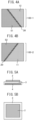
- FIG. 4A and FIG. 4B are views schematically showing one example of the cells 100-1 and 100-2 included in the stacked battery 100 of the second embodiment.
- FIG. 4A is a view of the cell 100-1 seen from a side of the cell 100-2 in the stacking direction of the stacked battery 100 of the second embodiment
- FIG. 4B is a view of the cell 100-2 seen from a side of the cell 100-1 in the stacking direction of the stacked battery 100 of the second embodiment.
- FIG. 5A to FIG. 8 are views for explaining a process of production of the stacked battery 100 of an example.
- FIG. 5A is a cross-sectional view of an assembly of the positive electrode 2, the separator 3, and the negative electrode 4 configuring part of the stacked battery 100 of the example
- FIG. 5B is a view of the assembly shown in FIG. 5A seen from above FIG. 5A
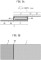
- FIG. 6A is a cross-sectional view of the assembly which is in a state in which the positive electrode current collector 1, the negative electrode current collector 5, and insulating material (seal material) 40 are added to the assembly shown in FIG. 5A
- FIG. 6B is a view of the assembly shown in FIG. 6A seen from above FIG. 6A .
- FIG. 5A is a cross-sectional view of an assembly of the positive electrode 2, the separator 3, and the negative electrode 4 configuring part of the stacked battery 100 of the example
- FIG. 5B is a view of the assembly shown in FIG. 5A seen from above FIG. 5A
- FIG. 7A is a cross-sectional view of the cell 100-1 configured by the second part 12 and the third part 13 of the positive electrode current collector 1 and the second part 52 and the third part 53 of the negative electrode current collector 5 of the assembly shown in FIG. 6A being wound around the positive electrode 2, the separator 3, and the negative electrode 4 via the first insulating material 20 and the second insulating material 30, while FIG. 7B is a view of the cell 100-1 shown in FIG. 7A seen from above FIG. 7A .
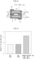
- FIG. 8 is a cross-sectional view of the stacked battery 100 configured by stacking the cell 100-1 shown in FIG. 7A and the cell 100-2 configured in the same way as the cell 100-1.
- FIG. 9 is a view showing in comparison a cell capacity of the cell 100-1 and the cell capacity of the cell 100-2 and the cell capacity of the stacked battery 100.
- the positive electrode material forming the positive electrode 2 LiNiCoMn, SE(LiI-LiBr-Li 2 S-P 2 S 5 ), VGCF, and SBR mixed together were used.
- the negative electrode material forming the negative electrode 4 graphite, SE (LiI-LiBr-Li 2 S-P 2 S 5 ), VGCF, and SBR mixed together were used.
- the material forming the separator 3 SE and SBR mixed together were used.
- the first insulating material 20 the second insulating material 30, and the insulating material (sealing material) 40, PP film was used.
- the positive electrode current collector 1 aluminum foil was used.
- As the negative electrode current collector 5 nickel foil was used.
- heating at 160°C for 1 minute was performed to seal the positive electrode 2, the separator 3, and the negative electrode 4 positioned between the positive electrode current collector 1 and the negative electrode current collector 5 by the insulating material (sealing material) 40.
- the second part 12 and the third part 13 of the positive electrode current collector 1 and the second part 52 and the third part 53 of the negative electrode current collector 5 were wound around the positive electrode 2, the separator 3, the negative electrode 4, and the insulating material (sealing material) 40. Heating at 160°C for 1 minute was performed to seal it by the first insulating material 20 and the second insulating material 30.
- the cell 100-1 shown in FIG. 7A and FIG. 7B is configured by sealing the electrode body 10 including the positive electrode current collector 1, the positive electrode 2, the separator 3 including the electrolyte, the negative electrode 4, and the negative electrode current collector 5 stacked in that order, by the positive electrode current collector 1, the negative electrode current collector 5, the first insulating material 20, and the second insulating material 30.
- heating at 160°C for 1 minute was performed to make the second insulating material 30 of the cell 100-1 and the first insulating material 20 of the cell 100-2 bond with each other and secure the electrical insulating property between the second part 12 of the positive electrode current collector 1 of the cell 100-1 and the second part 52 of the negative electrode current collector 5 of the cell 100-2.
- the stacked battery 100 shown in FIG. 8 is configured by the second part 12 of the positive electrode current collector 1 being wound over the first part 51 of the negative electrode current collector 5 via the second insulating material 30 and by the second part 52 of the negative electrode current collector 5 being wound over the first part 11 of the positive electrode current collector 1 via the first insulating material 20 so that the positive electrode current collector 1 contacts the positive electrode current collector 1 and the negative electrode current collector 5 contact the negative electrode current collector 5 at the time of stacking the cell 100-1 and the cell 100-2.
- the charging and discharging of the cell 100-1 and the cell 100-2 were evaluated under the following conditions:
- the stacked battery of the present disclosure is not limited to the above-mentioned embodiments and can be suitably changed within a range not deviating from the gist of the present disclosure.
- the configurations of the examples of the above-mentioned embodiments may also be be suitably combined.
Landscapes
- Chemical & Material Sciences (AREA)
- Chemical Kinetics & Catalysis (AREA)
- Electrochemistry (AREA)
- General Chemical & Material Sciences (AREA)
- Engineering & Computer Science (AREA)
- Manufacturing & Machinery (AREA)
- Physics & Mathematics (AREA)
- Condensed Matter Physics & Semiconductors (AREA)
- General Physics & Mathematics (AREA)
- Inorganic Chemistry (AREA)
- Materials Engineering (AREA)
- Secondary Cells (AREA)
Abstract
Description
- The present disclosure relates to a stacked battery.
- PTL 1 (
Japanese Unexamined Patent Publication No. 2003-168416 PTL 1, insulating boards are arranged at the top side and bottom side of a power generating element including positive electrode current collector, positive electrode, solid electrolyte, negative electrode, and negative electrode current collector stacked together. A metal pattern (extraction electrode) is provided at the top surface of the insulating board at the top side, while a metal pattern (extraction electrode) is provided at the bottom surface of the insulating board at the bottom side. Due to this, a unit cell of an all-solid-state battery is configured. - In the art described in
PTL 1, if, for example, two unit cells are stacked, the metal pattern provided at the bottom surface of the bottom side insulating board of the top side unit cell and the metal pattern provided at the top surface of the top side insulating board of the bottom side unit cell are made to contact. That is, in the art described inPTL 1, if, for example, two unit cells are stacked, between the power generating element of the top side unit cell and the power generating element of the bottom side unit cell, the bottom side insulating board of the top side unit cell, the metal pattern provided at the bottom surface of the bottom side insulating sheet of the top side unit cell, the top side insulating board of the bottom side unit cell, and the metal pattern provided at the top surface of the top side insulating board of the bottom side unit cell exist. For this reason, in the art described inPTL 1, it is not possible to sufficiently keep down the dimensions in the stacking direction of a stacked battery configured by stacking a plurality of unit cells. - In consideration of the above-mentioned point, the present disclosure has as its object the provision of a stacked battery able to sufficiently keep down the dimensions in the stacking direction.
- (1) One aspect of the present disclosure is a stacked battery including a stack of cells each having an electrode body including positive electrode current collector, positive electrode, electrolyte, negative electrode, and negative electrode current collector stacked in that order, a first insulating material arranged on an opposite side of the positive electrode across a first part of the positive electrode current collector, and a second insulating material arranged on an opposite side of the negative electrode across a first part of the negative electrode current collector, wherein the positive electrode current collector has the first part of the positive electrode current collector, a second part of the positive electrode current collector, and a third part of the positive electrode current collector extending in a stacking direction of the cells and connecting the first part of the positive electrode current collector and the second part of the positive electrode current collector, the second part of the positive electrode current collector is arranged on an opposite side of the first part of the negative electrode current collector across the second insulating material, the negative electrode current collector has the first part of the negative electrode current collector, a second part of the negative electrode current collector, and a third part of the negative electrode current collector extending in the stacking direction and connecting the first part of the negative electrode current collector and the second part of the negative electrode current collector, the second part of the negative electrode current collector is arranged on an opposite side from the first part of the positive electrode current collector across the first insulating material, the first insulating material is arranged so as not to overlap both of the second insulating material and the second part of the positive electrode current collector in the stacking direction, and the second part of the negative electrode current collector is arranged so as not to overlap both of the second insulating material and the second part of the positive electrode current collector in the stacking direction.
- (2) In the stacked battery of the aspect (1), the electrolyte may be a solid electrolyte.
- (3) In the stacked battery of the aspect (1), the thickness of a cell may be 0.1 to 2 mm.
- (4) In the stacked battery of the aspect (1), the third part of the positive electrode current collector may be arranged on an opposite side of the third part of the negative electrode current collector across the positive electrode, the electrolyte, and negative electrode.
- According to the present disclosure, it is possible to sufficiently keep down the dimensions of a stacked battery in the stacking direction.
-
-
FIG. 1A schematically shows one example of a cross-section of a stackedbattery 100 of the first embodiment. -
FIG. 1B shows a positive electrodecurrent collector 1 of a cell 100-1 included in thestacked battery 100 of the first embodiment shown inFIG. 1A pulled out. -
FIG. 1C shows a negative electrodecurrent collector 5 of the cell 100-1 included in thestacked battery 100 of the first embodiment shown inFIG. 1A pulled out. -
FIG. 2A is a view of the cell 100-1 seen from belowFIG. 1A . -
FIG. 2B is a view of a cell 100-2 seen from aboveFIG. 1A . -
FIG. 3 is a photo of a prototype of the cell 100-1 shown inFIG. 2A . -
FIG. 4A is a view of the cell 100-1 seen from a side of the cell 100-2 in the stacking direction of thestacked battery 100 of a second embodiment. -
FIG. 4B is a view of the cell 100-2 seen from a side of the cell 100-1 in the stacking direction of thestacked battery 100 of the second embodiment. -
FIG. 5A is a cross-sectional view of an assembly ofpositive electrode 2,separator 3, andnegative electrode 4 configuring part of the stackedbattery 100 of an example. -
FIG. 5B is a view of the assembly shown inFIG. 5A seen from aboveFIG. 5A . -
FIG. 6A is a cross-sectional view of the assembly which is in a state in which positive electrodecurrent collector 1, negative electrodecurrent collector 5, and insulating material (seal material) 40 are added to the assembly shown inFIG. 5A . -
FIG. 6B is a view of the assembly shown inFIG. 6A seen from aboveFIG. 6A . -
FIG. 7A is a cross-sectional view of the cell 100-1 configured bysecond part 12 andthird part 13 of the positive electrodecurrent collector 1 andsecond part 52 andthird part 53 of the negative electrodecurrent collector 5 of the assembly shown inFIG. 6A being wound around thepositive electrode 2, theseparator 3, and thenegative electrode 4 via firstinsulating material 20 and secondinsulating material 30. -
FIG. 7B is a view of the cell 100-1 shown inFIG. 7A seen from aboveFIG. 7A . -
FIG. 8 is a cross-sectional view of the stackedbattery 100 configured by stacking the cell 100-1 shown inFIG. 7A and the cell 100-2 configured in the same way as the cell 100-1. -
FIG. 9 is a view showing in comparison a cell capacity of the cell 100-1 and the cell capacity of the cell 100-2 and cell capacity of thestacked battery 100. - Below, embodiments of a stacked battery of the present disclosure will be explained with reference to the drawings.
-
FIG. 1A to FIG. 1C are views schematically showing one example of a stackedbattery 100 of a first embodiment. In more detail,FIG. 1A schematically shows the example of a cross-section of the stackedbattery 100 of the first embodiment,FIG. 1B shows a positive electrodecurrent collector 1 of a cell 100-1 included in the stackedbattery 100 of the first embodiment shown inFIG. 1A pulled out, andFIG. 1C shows a negative electrodecurrent collector 5 of the cell 100-1 included in the stackedbattery 100 of the first embodiment shown inFIG. 1A pulled out.FIG. 2A and FIG. 2B are views schematically showing one example of cells 100-1 and 100-2 included in the stackedbattery 100 of the first embodiment. In more detail,FIG. 2A is a view of the cell 100-1 seen from belowFIG. 1A , whileFIG. 2B is a view of a cell 100-2 seen from aboveFIG. 1A .FIG. 3 is a photo of a prototype of the cell 100-1 shown inFIG. 2A . - In the example shown in
FIG. 1A to FIG. 3 , the stackedbattery 100 includes the cell 100-1 and the cell 100-2 and is configured by stacking the cell 100-1 and the cell 100-2. - In another example, the stacked
battery 100 includes any number of cells other than two (however, several) and is configured by stacking these cells. - In the example shown in
FIG. 1A to FIG. 3 , the cell 100-1 and the cell 100-2 have the same configurations. - In another example, the respective configurations of the plurality of cells included in the stacked
battery 100 need not be completely the same. - In the example shown in
FIG. 1A to FIG. 3 , the cell 100-1 haselectrode body 10, first insulatingmaterial 20, and second insulatingmaterial 30. - The first insulating
material 20 and second insulatingmaterial 30 are configured by for example resin material having electrical insulation function and sealing function. - In more detail, in the example shown in
FIG. 3 , the first insulatingmaterial 20 and second insulatingmaterial 30 are configured by PP (polypropylene). - In another example, the first insulating
material 20 and second insulatingmaterial 30 may be configured by resin material other than PP film (however, resin material having the electrical insulation function and the sealing function). - In the example shown in
FIG. 1A to FIG. 3 , theelectrode body 10 includes positive electrodecurrent collector 1,positive electrode 2,separator 3 including electrolyte (for example, theseparator 3 in which the electrolyte is impregnated),negative electrode 4, and negative electrodecurrent collector 5 stacked in that order. - As the positive electrode
current collector 1, anything able to be used as the positive electrode current collector of this type of battery can be used without particular limitation. Typically, the positive electrodecurrent collector 1 is, for example, configured by a metal material having good conductivity such as aluminum, nickel, titanium, and stainless steel. - The positive electrode
current collector 1 is preferably a collector having oxidation resistance. In the example shown inFIG. 3 , as the positive electrodecurrent collector 1, aluminum foil is used. - As the positive electrode material forming the
positive electrode 2, for example, LiNiCoMn, SE (solid electrolyte) (LiI-LiBr-Li2 S-P2 S5 ), VGCF (vapor grown carbon fibers), and SBR (styrene-butadiene rubber) mixed together can be used. Positive electrode active substance, conductivity aid, and adhesive material contained in thepositive electrode 2 are not particularly designated. - That is, the
positive electrode 2 may also contain electrolyte. If thepositive electrode 2 contains the electrolyte, the electrolyte is preferably a solid electrolyte with a high heat resistance (sulfide or oxide). This is because a solid electrolyte which is strong against heat is necessary to enable hot bonding of the first insulatingmaterial 20 and second insulatingmaterial 30 used as the sealing material. - For example, an positive electrode composite paste obtained by mixing positive electrode active substance, conductivity aid, and binding material (adhesive material) and organic solvent (for example, N-methyl-2-pyrrolidone (NMP)) can be coated and dried on the positive electrode
current collector 1 to form an positive electrode composite layer on the positive electrodecurrent collector 1, then the positive electrode composite layer is rolled to a predetermined thickness to thereby prepare thepositive electrode 2. As the positive electrode active substance, for example, LiCoO2, LiNiO2, LiNia Cob O2 (a+b=1, 0<a<1, 0<b<1), LiMnO2, LiMn2 O4,
LiNia Cob Mnc O2 (a+b+c=1, 0<a<1, 0<b<1, 0<c<1), LiFePO4, etc. can be used. Further, as the conductivity aid, for example, acetylene black (AB) etc. can be used. As binder material, for example, polyvinylidene fluoride (PVdF) etc. can be used. - The electrolyte included in the
separator 3 is preferably the solid electrolyte having high heat resistance for the above-mentioned reason. - In the example shown in
FIG. 3 , as the material forming theseparator 3, SE and SBR mixed together are used. - The
separator 3 may be substantially comprised of solid electrolyte material. Theseparator 3, for example, may further contain a binder etc. Theseparator 3 can include any solid electrolyte material. Theseparator 3, for example, may include Li2 S-P2 S5 -based solid electrolyte etc. - As negative electrode material forming the
negative electrode 4, for example, graphite, SE (LiI-LiBr-Li2 S-P2 S5 ), VGCF, and SBR mixed together may be used. Negative electrode active substance, conductivity aid, and adhesive material contained in thenegative electrode 4 are not particularly designated. - That is, the
negative electrode 4 may contain electrolyte. If thenegative electrode 4 contains the electrolyte, the electrolyte is preferably the solid electrolyte with high heat resistance for the above-mentioned reason. - As the negative electrode
current collector 5, ones able to be used as the negative electrode current collector of this type of battery can be used without particular limitation. - The negative electrode
current collector 5 is preferably a current collector having reduction resistance. In the example shown inFIG. 3 , as the negative electrodecurrent collector 5, nickel foil is used. - As shown in
FIG. 1B , the positive electrodecurrent collector 1 hasfirst part 11,second part 12, andthird part 13. Thethird part 13 extends in the stacking direction (up-down direction ofFIG. 1B ) of the cell 100-1 and connects thefirst part 11 andsecond part 12. - As shown in
FIG. 1C , the negative electrodecurrent collector 5 hasfirst part 51,second part 52, andthird part 53. Thethird part 53 extends in the stacking direction (up-down direction ofFIG. 1C ) of the cell 100-1 and connects thefirst part 51 andsecond part 52. - As shown in
FIG. 1A and FIG. 1B , the first insulatingmaterial 20 is arranged on an opposite side (top side ofFIG. 1A ) of thepositive electrode 2 across thefirst part 11 of the positive electrodecurrent collector 1. - As shown in
FIG. 1A and FIG. 1C , the second insulatingmaterial 30 is arranged on an opposite side (bottom side ofFIG. 1A ) of thenegative electrode 4 across thefirst part 51 of the negative electrodecurrent collector 5. - As shown in
FIG. 1A, FIG. 1B, and FIG. 1C , thesecond part 12 of the positive electrodecurrent collector 1 is arranged on an opposite side (bottom side ofFIG. 1A, FIG. 1B, and FIG. 1C ) of thefirst part 51 of the negative electrodecurrent collector 5 across the second insulatingmaterial 30. Thesecond part 52 of the negative electrodecurrent collector 5 is arranged on an opposite side (top side ofFIG. 1A, FIG. 1B, and FIG. 1C ) of thefirst part 11 of the positive electrodecurrent collector 1 across the first insulatingmaterial 20. - As shown in
FIG. 1A, FIG. 1B, and FIG. 1C , thethird part 13 of the positive electrodecurrent collector 1 is arranged on an opposite side (right side ofFIG. 1A ) of thethird part 53 of the negative electrodecurrent collector 5 across thepositive electrode 2, theseparator 3 including the electrolyte, and thenegative electrode 4. - As shown in
FIG. 1A , the first insulatingmaterial 20 is arranged so as not to overlap the second insulatingmaterial 30 in the stacking direction (up-down direction ofFIG. 1A ) of the cell 100-1. That is, the position of the first insulatingmaterial 20 in the left-right direction ofFIG. 1A and the position of the second insulatingmaterial 30 in the left-right direction ofFIG. 1A are offset (made different). - As shown in
FIG. 1A and FIG. 1B , the first insulatingmaterial 20 is arranged so as not to overlap thesecond part 12 of the positive electrodecurrent collector 1 in the stacking direction of the cell 100-1. That is, the position of the first insulatingmaterial 20 in the left-right direction ofFIG. 1A and the position of thesecond part 12 of the positive electrodecurrent collector 1 in the left-right direction ofFIG. 1A are offset (made different). - As shown in
FIG. 1A and FIG. 1C , thesecond part 52 of the negative electrodecurrent collector 5 is arranged so as not to overlap the second insulatingmaterial 30 in the stacking direction of the cell 100-1. That is, the position of thesecond part 52 of thenegative electrode collector 5 in the left-right direction ofFIG. 1A and the position of the second insulatingmaterial 30 in the left-right direction ofFIG. 1A are offset (made different). - As shown in
FIG. 1A, FIG. 1B, and FIG. 1C , thesecond part 52 of the negative electrodecurrent collector 5 is arranged so as not to overlap thesecond part 12 of the positive electrodecurrent collector 1 in the stacking direction of the cell 100-1. That is, the position of thesecond part 52 of the negative electrodecurrent collector 5 in the left-right direction ofFIG. 1A and the position of thesecond part 12 of the positive electrodecurrent collector 1 in the left-right direction ofFIG. 1A are offset (made different). - In the example shown in
FIG. 1A to FIG. 3 , the respective thicknesses of the cells 100-1 and 100-2 in the stacking direction are, for example, 0.1 to 2 mm. - As a result, in the example shown in
FIG. 1A to FIG. 3 , thesecond part 12 of the positive electrodecurrent collector 1 of the cell 100-1 and thefirst part 11 of the positive electrodecurrent collector 1 of the cell 100-2 can be made to contact and thefirst part 51 of the negative electrodecurrent collector 5 of the cell 100-1 and thesecond part 52 of the negative electrodecurrent collector 5 of the cell 100-2 can be made to contact in order to stack the cell 100-1 and the cell 100-2 and can keep down the dimensions of the stackedbattery 100 in the stacking direction. - Further, in the example shown in
FIG. 1A to FIG. 3 , by stacking the cell 100-1 and the cell 100-2 in this way, it is possible to easily connect in parallel the cell 100-1 and the cell 100-2. - The stacked
battery 100 of a second embodiment is configured in the same way as thestacked battery 100 of the above-mentioned first embodiment except for the points explained later. -
FIG. 4A and FIG. 4B are views schematically showing one example of the cells 100-1 and 100-2 included in the stackedbattery 100 of the second embodiment. In more detail,FIG. 4A is a view of the cell 100-1 seen from a side of the cell 100-2 in the stacking direction of the stackedbattery 100 of the second embodiment, whileFIG. 4B is a view of the cell 100-2 seen from a side of the cell 100-1 in the stacking direction of the stackedbattery 100 of the second embodiment. - As shown in
FIG. 2A, FIG. 2B ,FIG. 4A, and FIG. 4B , when making thesecond part 12 of the positive electrodecurrent collector 1 of the cell 100-1 and thefirst part 11 of the positive electrodecurrent collector 1 of the cell 100-2 contact to stack the cell 100-1 and the cell 100-2, so long as thesecond part 12 of the positive electrodecurrent collector 1 of the cell 100-1 does not contact either of thesecond part 52 of the negative electrodecurrent collector 5 and first insulatingmaterial 20 of the cell 100-2, it is possible to set the shape of thesecond part 12 of the positive electrodecurrent collector 1 of the cell 100-1 shown inFIG. 2A andFIG. 4A to any shape. Further, when making thefirst part 51 of the negative electrodecurrent collector 5 of the cell 100-1 and thesecond part 52 of the negative electrodecurrent collector 5 of the cell 100-2 contact to stack the cell 100-1 and the cell 100-2, so long as thesecond part 52 of the negative electrodecurrent collector 5 of the cell 100-2 does not contact either of thesecond part 12 of the positive electrodecurrent collector 1 and second insulatingmaterial 30 of the cell 100-1, it is possible to set the shape of thesecond part 52 of the negative electrodecurrent collector 5 of the cell 100-2 shown inFIG. 2B andFIG. 4B to any shape. -
FIG. 5A to FIG. 8 are views for explaining a process of production of the stackedbattery 100 of an example. In more detail,FIG. 5A is a cross-sectional view of an assembly of thepositive electrode 2, theseparator 3, and thenegative electrode 4 configuring part of the stackedbattery 100 of the example, whileFIG. 5B is a view of the assembly shown inFIG. 5A seen from aboveFIG. 5A .FIG. 6A is a cross-sectional view of the assembly which is in a state in which the positive electrodecurrent collector 1, the negative electrodecurrent collector 5, and insulating material (seal material) 40 are added to the assembly shown inFIG. 5A , whileFIG. 6B is a view of the assembly shown inFIG. 6A seen from aboveFIG. 6A .FIG. 7A is a cross-sectional view of the cell 100-1 configured by thesecond part 12 and thethird part 13 of the positive electrodecurrent collector 1 and thesecond part 52 and thethird part 53 of the negative electrodecurrent collector 5 of the assembly shown inFIG. 6A being wound around thepositive electrode 2, theseparator 3, and thenegative electrode 4 via the first insulatingmaterial 20 and the second insulatingmaterial 30, whileFIG. 7B is a view of the cell 100-1 shown inFIG. 7A seen from aboveFIG. 7A .FIG. 8 is a cross-sectional view of the stackedbattery 100 configured by stacking the cell 100-1 shown inFIG. 7A and the cell 100-2 configured in the same way as the cell 100-1.FIG. 9 is a view showing in comparison a cell capacity of the cell 100-1 and the cell capacity of the cell 100-2 and the cell capacity of the stackedbattery 100. - In the example shown in
FIG. 5A to FIG. 9 , as the positive electrode material forming thepositive electrode 2, LiNiCoMn, SE(LiI-LiBr-Li2 S-P2 S5), VGCF, and SBR mixed together were used. As the negative electrode material forming thenegative electrode 4, graphite, SE (LiI-LiBr-Li2 S-P2 S5 ), VGCF, and SBR mixed together were used. As the material forming theseparator 3, SE and SBR mixed together were used. As the first insulatingmaterial 20, the second insulatingmaterial 30, and the insulating material (sealing material) 40, PP film was used. As the positive electrodecurrent collector 1, aluminum foil was used. As the negative electrodecurrent collector 5, nickel foil was used. - In the state shown in
FIG. 6A and FIG. 6B , heating at 160°C for 1 minute was performed to seal thepositive electrode 2, theseparator 3, and thenegative electrode 4 positioned between the positive electrodecurrent collector 1 and the negative electrodecurrent collector 5 by the insulating material (sealing material) 40. - In the state shown in
FIG. 7A and FIG. 7B , thesecond part 12 and thethird part 13 of the positive electrodecurrent collector 1 and thesecond part 52 and thethird part 53 of the negative electrodecurrent collector 5 were wound around thepositive electrode 2, theseparator 3, thenegative electrode 4, and the insulating material (sealing material) 40. Heating at 160°C for 1 minute was performed to seal it by the first insulatingmaterial 20 and the second insulatingmaterial 30. - The cell 100-1 shown in
FIG. 7A and FIG. 7B is configured by sealing theelectrode body 10 including the positive electrodecurrent collector 1, thepositive electrode 2, theseparator 3 including the electrolyte, thenegative electrode 4, and the negative electrodecurrent collector 5 stacked in that order, by the positive electrodecurrent collector 1, the negative electrodecurrent collector 5, the first insulatingmaterial 20, and the second insulatingmaterial 30. - In the state shown in
FIG. 8 , heating at 160°C for 1 minute was performed to make the second insulatingmaterial 30 of the cell 100-1 and the first insulatingmaterial 20 of the cell 100-2 bond with each other and secure the electrical insulating property between thesecond part 12 of the positive electrodecurrent collector 1 of the cell 100-1 and thesecond part 52 of the negative electrodecurrent collector 5 of the cell 100-2. - The stacked
battery 100 shown inFIG. 8 is configured by thesecond part 12 of the positive electrodecurrent collector 1 being wound over thefirst part 51 of the negative electrodecurrent collector 5 via the second insulatingmaterial 30 and by thesecond part 52 of the negative electrodecurrent collector 5 being wound over thefirst part 11 of the positive electrodecurrent collector 1 via the first insulatingmaterial 20 so that the positive electrodecurrent collector 1 contacts the positive electrodecurrent collector 1 and the negative electrodecurrent collector 5 contact the negative electrodecurrent collector 5 at the time of stacking the cell 100-1 and the cell 100-2. - The charging and discharging of the cell 100-1 and the cell 100-2 were evaluated under the following conditions:
- 4.0 to 3.0V
- 0.6 mA/cm2
- 25°C
- Using the stacked
battery 100 including the cell 100-1 and the cell 100-2 stacked together, charging and discharging were performed under the following conditions: - 4.0 to 3.0V
- 1.2 mA/cm2
- 25°C
- The respective CC (constant current) discharge capacities of the cell 100-1, the cell 100-2, and the stacked
battery 100 became as shown inFIG. 9 . It was confirmed that parallel capacities (capacity of cell 100-1 + capacity of cell 100-2) can be realized by simple stacking of the cell 100-1 and the cell 100-2. - In the above way, embodiments of the stacked battery of the present disclosure were explained with reference to the drawings, but the stacked battery of the present disclosure is not limited to the above-mentioned embodiments and can be suitably changed within a range not deviating from the gist of the present disclosure. The configurations of the examples of the above-mentioned embodiments may also be be suitably combined.
Claims (4)
- A stacked battery comprising a stack of cells each having an electrode body including positive electrode current collector, positive electrode, electrolyte, negative electrode, and negative electrode current collector stacked in that order, a first insulating material arranged on an opposite side of the positive electrode across a first part of the positive electrode current collector, and a second insulating material arranged on an opposite side of the negative electrode across a first part of the negative electrode current collector, whereinthe positive electrode current collector has the first part of the positive electrode current collector, a second part of the positive electrode current collector, and a third part of the positive electrode current collector extending in a stacking direction of the cells and connecting the first part of the positive electrode current collector and the second part of the positive electrode current collector,the second part of the positive electrode current collector is arranged on an opposite side of the first part of the negative electrode current collector across the second insulating material,the negative electrode current collector has the first part of the negative electrode current collector, a second part of the negative electrode current collector, and a third part of the negative electrode current collector extending in the stacking direction and connecting the first part of the negative electrode current collector and the second part of the negative electrode current collector,the second part of the negative electrode current collector is arranged on an opposite side from the first part of the positive electrode current collector across the first insulating material,the first insulating material is arranged so as not to overlap both of the second insulating material and the second part of the positive electrode current collector in the stacking direction, andthe second part of the negative electrode current collector is arranged so as not to overlap both of the second insulating material and the second part of the positive electrode current collector in the stacking direction.
- The stacked battery according to claim 1, wherein the electrolyte is a solid electrolyte.
- The stacked battery according to claim 1, wherein the thickness of a cell is 0.1 to 2 mm.
- The stacked battery according to claim 1, wherein the third part of the positive electrode current collector is arranged on an opposite side of the third part of the negative electrode current collector across the positive electrode, the electrolyte, and negative electrode.
Applications Claiming Priority (1)
| Application Number | Priority Date | Filing Date | Title |
|---|---|---|---|
| JP2023036599A JP7670081B2 (en) | 2023-03-09 | 2023-03-09 | Stacked battery |
Publications (3)
| Publication Number | Publication Date |
|---|---|
| EP4428956A1 true EP4428956A1 (en) | 2024-09-11 |
| EP4428956B1 EP4428956B1 (en) | 2025-09-03 |
| EP4428956C0 EP4428956C0 (en) | 2025-09-03 |
Family
ID=89977745
Family Applications (1)
| Application Number | Title | Priority Date | Filing Date |
|---|---|---|---|
| EP24157909.3A Active EP4428956B1 (en) | 2023-03-09 | 2024-02-15 | Stacked battery |
Country Status (5)
| Country | Link |
|---|---|
| US (1) | US20240304824A1 (en) |
| EP (1) | EP4428956B1 (en) |
| JP (1) | JP7670081B2 (en) |
| KR (1) | KR102858955B1 (en) |
| CN (1) | CN118630288A (en) |
Citations (3)
| Publication number | Priority date | Publication date | Assignee | Title |
|---|---|---|---|---|
| JP2003168416A (en) | 2001-12-04 | 2003-06-13 | Matsushita Electric Ind Co Ltd | All-solid-state battery and method of manufacturing the same |
| JP2012204160A (en) * | 2011-03-25 | 2012-10-22 | Kyocera Corp | Secondary battery |
| US8389144B2 (en) * | 2006-06-13 | 2013-03-05 | Gs Nanotech Co., Ltd. | Reserve battery having all solid state thin film battery |
Family Cites Families (6)
| Publication number | Priority date | Publication date | Assignee | Title |
|---|---|---|---|---|
| JP6492959B2 (en) | 2014-05-19 | 2019-04-03 | Tdk株式会社 | Solid battery |
| JP2017126471A (en) | 2016-01-13 | 2017-07-20 | 株式会社Gsユアサ | Power storage element |
| JP6721053B2 (en) | 2016-09-21 | 2020-07-08 | 株式会社豊田自動織機 | Power storage device and method of manufacturing power storage device |
| KR102303678B1 (en) * | 2019-02-12 | 2021-09-16 | 도요타 지도샤(주) | All-solid-state battery stack |
| JP7476788B2 (en) * | 2020-12-25 | 2024-05-01 | トヨタ自動車株式会社 | Battery Module |
| JPWO2024062777A1 (en) | 2022-09-21 | 2024-03-28 |
-
2023
- 2023-03-09 JP JP2023036599A patent/JP7670081B2/en active Active
-
2024
- 2024-02-07 US US18/435,630 patent/US20240304824A1/en active Pending
- 2024-02-15 EP EP24157909.3A patent/EP4428956B1/en active Active
- 2024-03-06 KR KR1020240032128A patent/KR102858955B1/en active Active
- 2024-03-07 CN CN202410258675.XA patent/CN118630288A/en active Pending
Patent Citations (3)
| Publication number | Priority date | Publication date | Assignee | Title |
|---|---|---|---|---|
| JP2003168416A (en) | 2001-12-04 | 2003-06-13 | Matsushita Electric Ind Co Ltd | All-solid-state battery and method of manufacturing the same |
| US8389144B2 (en) * | 2006-06-13 | 2013-03-05 | Gs Nanotech Co., Ltd. | Reserve battery having all solid state thin film battery |
| JP2012204160A (en) * | 2011-03-25 | 2012-10-22 | Kyocera Corp | Secondary battery |
Also Published As
| Publication number | Publication date |
|---|---|
| US20240304824A1 (en) | 2024-09-12 |
| JP2024127442A (en) | 2024-09-20 |
| JP7670081B2 (en) | 2025-04-30 |
| EP4428956B1 (en) | 2025-09-03 |
| KR20240138029A (en) | 2024-09-20 |
| EP4428956C0 (en) | 2025-09-03 |
| KR102858955B1 (en) | 2025-09-11 |
| CN118630288A (en) | 2024-09-10 |
Similar Documents
| Publication | Publication Date | Title |
|---|---|---|
| JP4644899B2 (en) | Electrode and battery, and manufacturing method thereof | |
| JP4041044B2 (en) | Method for manufacturing electrochemical device | |
| KR102303703B1 (en) | Solid-state battery and method for manufacturing the same | |
| KR101604834B1 (en) | Structure for electrode assembly and Stack-folding typed electrode assembly prepared from the same | |
| KR101152651B1 (en) | Secondary Battery of Improved Stability by Both Sides Adhesive Tape | |
| US20100055565A1 (en) | Electrode manufacturing method and electrode | |
| TW201547085A (en) | Sheet-laminated lithium ion secondary battery and method for producing sheet-laminated lithium ion secondary battery | |
| CN109565069B (en) | Electrode assembly and method of manufacturing the same | |
| KR102734360B1 (en) | Electrochemical Device for Short Circuit Induction and Method of Evaluation for Safety Using Thereof | |
| JPWO2012111061A1 (en) | Battery and battery manufacturing method | |
| CN113748535A (en) | Positive electrode for lithium ion secondary battery, positive electrode sheet for lithium ion secondary battery, and method for producing same | |
| CN107534129B (en) | Electrodes, electrode groups and non-aqueous electrolyte batteries | |
| KR20100051353A (en) | Stacked electrochemical cell | |
| US20250239622A1 (en) | Lithium secondary battery and method for manufacturing same | |
| JP5348720B2 (en) | Flat non-aqueous secondary battery | |
| CN111527627A (en) | Method for manufacturing negative electrode and negative electrode obtained therefrom | |
| JPWO2006118053A1 (en) | battery | |
| CN111326707A (en) | Laminated battery and method of manufacturing the same | |
| KR101156954B1 (en) | Electrode Assembly with Excellent Weldability between Electrode Lead and Electrode Tabs and Secondary Battery Comprising the Same | |
| EP3993089B1 (en) | Method for manufacturing electrode on which resistance layer is formed | |
| KR102164576B1 (en) | Method Preparing Electrode Assembly And Electrode Assembly Prepared Using the Same | |
| US11870039B2 (en) | Electrode assembly and method for manufacturing the same | |
| CN111354922A (en) | Wound battery and method for manufacturing wound battery | |
| JP5755870B2 (en) | Positive electrode for secondary battery, secondary battery, and method for producing positive electrode for secondary battery | |
| CN113767517B (en) | Electrochemical device including short-circuit inducing member and safety evaluation method using the same |
Legal Events
| Date | Code | Title | Description |
|---|---|---|---|
| PUAI | Public reference made under article 153(3) epc to a published international application that has entered the european phase |
Free format text: ORIGINAL CODE: 0009012 |
|
| STAA | Information on the status of an ep patent application or granted ep patent |
Free format text: STATUS: REQUEST FOR EXAMINATION WAS MADE |
|
| 17P | Request for examination filed |
Effective date: 20240301 |
|
| AK | Designated contracting states |
Kind code of ref document: A1 Designated state(s): AL AT BE BG CH CY CZ DE DK EE ES FI FR GB GR HR HU IE IS IT LI LT LU LV MC ME MK MT NL NO PL PT RO RS SE SI SK SM TR |
|
| GRAP | Despatch of communication of intention to grant a patent |
Free format text: ORIGINAL CODE: EPIDOSNIGR1 |
|
| STAA | Information on the status of an ep patent application or granted ep patent |
Free format text: STATUS: GRANT OF PATENT IS INTENDED |
|
| INTG | Intention to grant announced |
Effective date: 20250325 |
|
| GRAS | Grant fee paid |
Free format text: ORIGINAL CODE: EPIDOSNIGR3 |
|
| GRAA | (expected) grant |
Free format text: ORIGINAL CODE: 0009210 |
|
| STAA | Information on the status of an ep patent application or granted ep patent |
Free format text: STATUS: THE PATENT HAS BEEN GRANTED |
|
| AK | Designated contracting states |
Kind code of ref document: B1 Designated state(s): AL AT BE BG CH CY CZ DE DK EE ES FI FR GB GR HR HU IE IS IT LI LT LU LV MC ME MK MT NL NO PL PT RO RS SE SI SK SM TR |
|
| REG | Reference to a national code |
Ref country code: CH Ref legal event code: EP |
|
| REG | Reference to a national code |
Ref country code: DE Ref legal event code: R096 Ref document number: 602024000552 Country of ref document: DE |
|
| REG | Reference to a national code |
Ref country code: IE Ref legal event code: FG4D |
|
| U01 | Request for unitary effect filed |
Effective date: 20250918 |
|
| U07 | Unitary effect registered |
Designated state(s): AT BE BG DE DK EE FI FR IT LT LU LV MT NL PT RO SE SI Effective date: 20250924 |
|
| REG | Reference to a national code |
Ref country code: GR Ref legal event code: EP Ref document number: 20250402171 Country of ref document: GR Effective date: 20251210 |
|
| PG25 | Lapsed in a contracting state [announced via postgrant information from national office to epo] |
Ref country code: NO Free format text: LAPSE BECAUSE OF FAILURE TO SUBMIT A TRANSLATION OF THE DESCRIPTION OR TO PAY THE FEE WITHIN THE PRESCRIBED TIME-LIMIT Effective date: 20251203 |
|
| PG25 | Lapsed in a contracting state [announced via postgrant information from national office to epo] |
Ref country code: HR Free format text: LAPSE BECAUSE OF FAILURE TO SUBMIT A TRANSLATION OF THE DESCRIPTION OR TO PAY THE FEE WITHIN THE PRESCRIBED TIME-LIMIT Effective date: 20250903 |
|
| PG25 | Lapsed in a contracting state [announced via postgrant information from national office to epo] |
Ref country code: PL Free format text: LAPSE BECAUSE OF FAILURE TO SUBMIT A TRANSLATION OF THE DESCRIPTION OR TO PAY THE FEE WITHIN THE PRESCRIBED TIME-LIMIT Effective date: 20250903 |
|
| PG25 | Lapsed in a contracting state [announced via postgrant information from national office to epo] |
Ref country code: RS Free format text: LAPSE BECAUSE OF FAILURE TO SUBMIT A TRANSLATION OF THE DESCRIPTION OR TO PAY THE FEE WITHIN THE PRESCRIBED TIME-LIMIT Effective date: 20251203 |
|
| PG25 | Lapsed in a contracting state [announced via postgrant information from national office to epo] |
Ref country code: ES Free format text: LAPSE BECAUSE OF FAILURE TO SUBMIT A TRANSLATION OF THE DESCRIPTION OR TO PAY THE FEE WITHIN THE PRESCRIBED TIME-LIMIT Effective date: 20250903 |
|
| U20 | Renewal fee for the european patent with unitary effect paid |
Year of fee payment: 3 Effective date: 20260106 |
|
| PG25 | Lapsed in a contracting state [announced via postgrant information from national office to epo] |
Ref country code: SM Free format text: LAPSE BECAUSE OF FAILURE TO SUBMIT A TRANSLATION OF THE DESCRIPTION OR TO PAY THE FEE WITHIN THE PRESCRIBED TIME-LIMIT Effective date: 20250903 |
|
| PGFP | Annual fee paid to national office [announced via postgrant information from national office to epo] |
Ref country code: IE Payment date: 20260102 Year of fee payment: 3 |
|
| PG25 | Lapsed in a contracting state [announced via postgrant information from national office to epo] |
Ref country code: IS Free format text: LAPSE BECAUSE OF FAILURE TO SUBMIT A TRANSLATION OF THE DESCRIPTION OR TO PAY THE FEE WITHIN THE PRESCRIBED TIME-LIMIT Effective date: 20260103 |
|
| PGFP | Annual fee paid to national office [announced via postgrant information from national office to epo] |
Ref country code: TR Payment date: 20260211 Year of fee payment: 3 |
|
| PG25 | Lapsed in a contracting state [announced via postgrant information from national office to epo] |
Ref country code: CZ Free format text: LAPSE BECAUSE OF FAILURE TO SUBMIT A TRANSLATION OF THE DESCRIPTION OR TO PAY THE FEE WITHIN THE PRESCRIBED TIME-LIMIT Effective date: 20250903 |
|
| PGFP | Annual fee paid to national office [announced via postgrant information from national office to epo] |
Ref country code: GR Payment date: 20260114 Year of fee payment: 3 |
|
| PG25 | Lapsed in a contracting state [announced via postgrant information from national office to epo] |
Ref country code: SK Free format text: LAPSE BECAUSE OF FAILURE TO SUBMIT A TRANSLATION OF THE DESCRIPTION OR TO PAY THE FEE WITHIN THE PRESCRIBED TIME-LIMIT Effective date: 20250903 |
|
| U1N | Appointed representative for the unitary patent procedure changed after the registration of the unitary effect |
Representative=s name: MARKS & CLERK LLP; GB |