EP4428893A1 - Operating mechanism for zero volt coil spring in circuit breaker - Google Patents
Operating mechanism for zero volt coil spring in circuit breaker Download PDFInfo
- Publication number
- EP4428893A1 EP4428893A1 EP23160189.9A EP23160189A EP4428893A1 EP 4428893 A1 EP4428893 A1 EP 4428893A1 EP 23160189 A EP23160189 A EP 23160189A EP 4428893 A1 EP4428893 A1 EP 4428893A1
- Authority
- EP
- European Patent Office
- Prior art keywords
- zvc
- charging
- plunger
- spring
- lever
- Prior art date
- Legal status (The legal status is an assumption and is not a legal conclusion. Google has not performed a legal analysis and makes no representation as to the accuracy of the status listed.)
- Pending
Links
Images






Classifications
-
- H—ELECTRICITY
- H01—ELECTRIC ELEMENTS
- H01H—ELECTRIC SWITCHES; RELAYS; SELECTORS; EMERGENCY PROTECTIVE DEVICES
- H01H83/00—Protective switches, e.g. circuit-breaking switches, or protective relays operated by abnormal electrical conditions otherwise than solely by excess current
- H01H83/12—Protective switches, e.g. circuit-breaking switches, or protective relays operated by abnormal electrical conditions otherwise than solely by excess current operated by voltage falling below a predetermined value, e.g. for no-volt protection
-
- H—ELECTRICITY
- H01—ELECTRIC ELEMENTS
- H01H—ELECTRIC SWITCHES; RELAYS; SELECTORS; EMERGENCY PROTECTIVE DEVICES
- H01H3/00—Mechanisms for operating contacts
- H01H3/22—Power arrangements internal to the switch for operating the driving mechanism
- H01H3/30—Power arrangements internal to the switch for operating the driving mechanism using spring motor
- H01H3/3005—Charging means
- H01H3/3015—Charging means using cam devices
-
- H—ELECTRICITY
- H01—ELECTRIC ELEMENTS
- H01H—ELECTRIC SWITCHES; RELAYS; SELECTORS; EMERGENCY PROTECTIVE DEVICES
- H01H3/00—Mechanisms for operating contacts
- H01H3/32—Driving mechanisms, i.e. for transmitting driving force to the contacts
- H01H3/42—Driving mechanisms, i.e. for transmitting driving force to the contacts using cam or eccentric
-
- H—ELECTRICITY
- H01—ELECTRIC ELEMENTS
- H01H—ELECTRIC SWITCHES; RELAYS; SELECTORS; EMERGENCY PROTECTIVE DEVICES
- H01H33/00—High-tension or heavy-current switches with arc-extinguishing or arc-preventing means
- H01H33/02—Details
- H01H33/28—Power arrangements internal to the switch for operating the driving mechanism
- H01H33/40—Power arrangements internal to the switch for operating the driving mechanism using spring motor
Definitions
- the present disclosure generally relates to circuit breaker drive mechanisms. More particularly, it relates to providing multiple charging and discharging mechanisms for a zero volt coil, ZVC, spring in a circuit breaker.
- Protection systems that include logic circuits, sensors, relays, circuit breakers, fuses, isolators, instrument transformers, and other protection devices, are provided in electrical power systems to control, protect and isolate electrical equipment of the electrical power systems during any electrical fault.
- the electrical fault may correspond to an abnormal condition in the electrical power system, which may damage the electrical equipment and disturb normal flow of electric current in the electrical power system.
- the electrical fault may occur in one or more of three phases or a power line of the electrical power system.
- the potential energy required for opening and closing operations of the circuit breaker may be provided by an operating mechanism, such as a spring operating mechanism/circuit breaking mechanism.
- the spring operating mechanism may have potential energy mechanically stored in springs.
- different spring operating mechanisms such as BLK, BLG, MSD, and FSA, may be used based on a rating of the power line to be isolated or a rating of the circuit breaker.
- the circuit breaker comprises a ZVC, a ZVC plunger connected to the ZVC, and a ZVC spring connected to the ZVC plunger.
- Available FSA-ZVC based spring operating mechanism of the circuit breaker requires additional components/devices such as resistor, timer, contactor, under voltage relay, and so on, to satisfy International Organization for Standardization/International Electro technical Commission, IEC, requirements of tripping the circuit breaker below specified percentage of rated voltage.
- a device for an electrical circuit comprises a zero-volt coil, ZVC.
- the device comprises a ZVC plunger, which is arranged to be displaced between a charged position in which it is held by a magnetic field generated by the ZVC and a discharged position in which it is released by the ZVC.
- the device comprises a ZVC spring connected to the ZVC plunger.
- the ZVC spring is operable between a charged position corresponding to the charged position of the ZVC plunger and a discharged position corresponding to the discharged position of the ZVC plunger.
- the device comprises a circuit breaking mechanism.
- the device comprises a charging mechanism for displacing the ZVC spring to its charged position.
- the device comprises a discharging mechanism configured to be connected to the ZVC plunger and to be displaced by the ZVC spring and the ZVC plunger upon discharging of the ZVC spring and the ZVC plunger into a position in which it triggers the circuit breaking mechanism to break the electrical circuit.
- the charging mechanism comprises a plural linkage mechanism configured to be connected in one end to the ZVC plunger for enabling charging of the ZVC plunger and of the ZVC spring through a pivotation of at least one of the links of the plural linkage mechanism.
- the discharging mechanism comprises a plural linkage mechanism connected in one end to the ZVC plunger and in an opposite end with the circuit breaking mechanism.
- the ZVC spring When in its charged position, the ZVC spring exerts a force on the ZVC plunger in a direction in which it strives at forcing the ZVC plunger in a direction away from its charged position, in which the ZVC plunger is held by the ZVC upon application of a voltage onto the ZVC towards the discharged position of the ZVC plunger, such that, upon application of the predetermined reduced voltage on the ZVC.
- the ZVC plunger is moved in said direction by the action of the ZVC spring to adapt its discharged position, for the purpose of initiating circuit breaking by the device.
- the charging mechanism comprises a rotary retention lever, wherein a rotation of the retention lever causes a displacement of the links of the plural linkage mechanism to a position in which the ZVC plunger and the ZVC spring are in their respective charged position and in which said spacing between at least two links of the plural linkage mechanism is present.
- the device disclosed herein implements charging and discharging mechanisms for charging the ZVC spring and for disengaging the plural linkage mechanism of the charging mechanism, thereby breaking the electrical circuit.
- the ZVC spring may be charged during opening or closing operation of the device.
- the charging and discharging mechanisms implemented by the device may be designed by considering one or more of: no dependency on open orientation of a charging lever of the charging mechanism, a minimum number of links in the charging mechanism, minimum horizontal force on the ZVC plunger, and high margin for force available to trip/break the device.
- the plural linkage mechanism of the charging mechanism comprises a charging lever configured to be connected to the ZVC plunger and to be releasably connected to the retention lever and a cam element configured to be connected to the charging lever by means of a coupler.
- the discharging mechanism comprises an L-bracket connected in one end to the ZVC plunger, a connection strip connected to the L-bracket, and a bend bracket connected to the connection strip.
- the retention lever is configured to rotate by exceeding a first pre-defined threshold for causing rotation of the charging lever and for further causing rotation of the cam element to displace the ZVC plunger and the ZVC spring to their respective charged position.
- the charging lever comprises a spring configured to rotate the charging lever, when the charging lever crosses a first toggle positon during charging of the ZVC spring and the ZVC plunger to their respective charged position by the action of the charging mechanism and a stopper pin configured to stop rotation of the charging lever, when the charging lever crosses a second toggle position during charging of the ZVC spring and the ZVC plunger to their respective charged position by the action of the charging mechanism.
- a pin mounted on the cam element is configured to slide inside a slot of a slotted lever pivotally connected to the L-bracket, and the retention lever is configured to rotate further to a position in which said spacing exists between the retention lever and the charging lever.
- the discharging mechanism upon discharging of the ZVC spring, is configured to disturb an equilibrium state of the circuit breaking mechanism and the slotted lever is configured to cause rotation of the cam element and the charging lever.
- the charging mechanism comprises a retention lever and a charging lever configured to be connected to the ZVC plunger and to be releasably connected to the retention lever.
- the discharging mechanism comprises a connection link connected in one end to the ZVC plunger, a connection strip connected to the connection link, and a bend bracket connected to the connection strip and to the circuit breaking mechanism, and wherein the charging lever is connected to the ZVC plunger via the connecting link.
- the retention lever is configured to rotate by exceeding a first pre-defined threshold for causing rotation of the charging lever to displace the ZVC plunger and the ZVC spring via the connection link to their respective charged position.
- the retention lever is configured to rotate back in an opposite direction such that, when the ZVC spring is in the charged position, the retention lever and the charging lever are spaced apart by said spacing.
- the ZVC spring is configured to displace the plunger and the connection link, to which the charging lever is connected, and thereby causing rotation of the charging lever back to a position in which it will be releasably connected by the retention lever upon rotation of the retention lever to said first threshold during a subsequent charging operation, and to further cause the bend bracket to disturb an equilibrium state of the circuit breaking mechanism and thereby trigger the circuit breaking mechanism to break an electric circuit.
- the charging mechanism comprises a retention lever, a coupler connected to the retention lever, and an oscillator connected to the coupler.
- the discharging mechanism comprises a connecting link connected in one end to the ZVC plunger, a charging link connected to the connecting link, and a connection strip connected in one end to the charging link, and a bend bracket connected in one end to the connection strip and in an opposite end to the circuit breaking mechanism.
- the oscillator has a charging pin, which is connectable to the charging link and configured to push the charging link upon a predetermined rotation of the retention lever and thereby induce charging motion of the ZVC plunger and the ZVC spring and wherein, after rotation of the retention lever such that charging of the ZVC plunger and ZVC spring is achieved, the retention lever is configured to be rotated in an opposite direction such that said spacing is formed between said charging pin and the charging link.
- the retention lever is configured to displace the oscillator, which is configured to push the charging link at an end of an opening stroke for enabling the charging link, the connecting link, and the ZVC plunger to displace the ZVC spring and the ZVC plunger to their respective charged position.
- the charging link, the connection strip, and the bend bracket are configured to move for bringing the circuit breaking mechanism to a latched condition.
- the charging mechanism comprises a charging lever, which is spring-loaded such that it exerts a charging force on the ZVC plunger and wherein the charging mechanism comprises a retention lever, which is configured to be rotated such that it counteracts the spring load on the charging lever, and wherein, after charging of the ZVC plunger and the ZVC spring by the action of the charging lever, the retention lever is configured to be rotated to a predetermined angular position such that it pivots the charging lever to a position in which said spacing is present between the charging lever and the ZVC plunger.
- the charging mechanism comprises a charging lever which is spring-loaded such that it exerts a charging force on the ZVC plunger
- the charging mechanism comprises a retention lever which is configured to be rotated such that it counteracts the spring load on the charging lever, and wherein, after charging of the ZVC plunger and the ZVC spring by the action of the charging lever the retention lever is configured to be rotated to a predetermined angular position such that it pivots the charging lever to a position in which said spacing is present between the charging lever and the ZVC plunger.
- the retention lever is configured to engage and close the circuit breaker mechanism upon being rotated to said predetermined angular position, and wherein, upon discharging of the ZVC plunger, the discharging mechanism will trigger an opening of the circuit breaker mechanism, which opening will trigger a rotation of the retention lever to an angular position in which the retention lever does not engage the charging lever, thereby enabling the charging lever to apply its spring force on the ZVC plunger for the charging thereof.
- the charging mechanism comprises the retention lever and the charging lever, and a stop pin, wherein the stop pin is configured to prevent the charging lever from pivoting beyond a point at which remaining motion of the ZVC plunger to its charged position is enabled by application of a predetermined voltage on the ZVC.
- the discharging mechanism comprises an L-bracket, a connection strip connected to the L-bracket and a bend bracket connected to the connection strip and to the circuit breaking mechanism.
- the device further comprises a torsion spring configured to apply said spring load on the charging lever, and a spring stopper pin configured to support a fixed leg of the torsion spring.
- the charging lever is configured to displace the ZVC plunger by means of the torsion spring for displacing the ZVC spring and the ZVC plunger to their respective charged position.
- the retention lever is configured to rotate and interact with the charging lever for causing the charging lever to rotate and disengage from the ZVC plunger, wherein when the ZVC spring is in the charged position, the retention lever is configured to lock on the circuit breaker mechanism.
- the ZVC spring when the ZVC spring moves to its discharged position during the closing operation of the circuit breaker, the ZVC spring is configured to transfer energy to a latch catch of the circuit breaking mechanism by means of the discharging mechanism and the charging mechanism for disturbing an equilibrium of the circuit breaking mechanism and to further release the retention lever from the circuit breaking mechanism.
- the ZVC spring when the circuit breaker is being operated from the closing operation to the opening operation, is configured to displace the plunger for discharging mechanism to disturb an equilibrium of the circuit breaker mechanism for tripping of the circuit breaker.
- the retention lever when the circuit breaker is being tripped, is configured to rotate for causing rotation of the charging lever to displace the plunger for enabling the ZVC spring to move towards the charged position.
- the circuit breaker further comprises a blockage assembly comprising a threaded bush and is configured to lock the plunger in a locked condition using a bolt for mechanically blocking the ZVC spring and a microswitch configured to provide an alert indicating that the ZVC spring is being blocked.
- the circuit breaker further comprises: a holder configured to be mounted on the latch shaft, a latch link configured to be assembled on the holder using a pin, a latch torsion spring configured to be arranged between the holder and the latch link and over the pin.
- the latch link is operated against a torque of the latch torsion spring for manually tripping the circuit breaker.
- any of the above aspects may additionally have features identical with or corresponding to any of the various features as explained above for any of the other aspects.
- Embodiments herein disclose a device for an electrical circuit.
- the device referred herein may be a circuit breaker or a switching device, configured to be operated manually and/or automatically for controlling and protecting the electrical circuit (also be referred to as electrical equipment) of an electrical power system.
- the device may operate to, for example, control opening and/or closing of the electrical circuit (specifically, a power line) to control flow of current through the circuit.
- the device may be provided at terminals of the power line for de-energization of a fault circuit or a faulty power line.
- the device referred herein may be a high voltage circuit breaker.
- an Intelligent Electronic Device On detecting high fault current, an Intelligent Electronic Device, IED, may send an opening signal to the device. On receiving the opening signal, the device may interrupt current flow in the power line. Once the fault is cleared, the device may be reset or closed to resume normal operation of the power line and the electrical power system, either manually or automatically. A sufficient mechanical power/potential energy is required for the opening and closing operation of the device.
- the required potential energy for the opening and closing operation of the device may be provided by a spring operating mechanism.
- the spring operating mechanism may be BLK.
- the device being operated in accordance with BLK comprises a zero volt coil, ZVC, spring coupled to a ZVC through a ZVC plunger.
- BLK-ZVC based spring operating mechanism of the device satisfy International Organization for Standardization/International Electro technical Commission, IEC, requirements of tripping the device below specified percentage of rated voltage without additional components such as resistor, timer, contactor, under voltage relay, and so on.
- IEC International Organization for Standardization/International Electro technical Commission
- BLK-ZVC charges the ZVC spring through an external force.
- the device implements or triggers one of multiple (for example, first, second, third, fourth) charging and discharging mechanisms for efficient charging of the ZVC spring and for disengaging a charging mechanism configured for displacing the ZVC spring to its charged position.
- first and second charging and discharging mechanisms the ZVC spring is charged during a closing operation of the device.
- third and fourth charging and discharging mechanisms the ZVC spring is charged during an opening operation of the device.
- the device configured for implementing multiple charging and discharging mechanisms comprises a ZVC, a ZVC plunger, a ZVC spring, a circuit breaking mechanism, a charging mechanism, and a discharging mechanism.
- the ZVC plunger is arranged to be displaced between a charged position and a discharged position. In the charged position, the ZVC plunger is held by a magnetic field generated by the ZVC. In the discharged position, the ZVC plunger is released by the ZVC as a result of a predetermined voltage reduction in the ZVC and displaced relative to the charged position.
- the ZVC spring is connected to the ZVC plunger.
- the ZVC spring is operable between a charged position corresponding to the charged position of the ZVC plunger and a discharged position corresponding to the discharged position of the ZVC plunger. In its charged position, the ZVC spring exerts a force on the ZVC plunger in a direction in which it strives at forcing the ZVC plunger in a direction away from its charged position in which the ZVC plunger is held by the ZVC upon application of a voltage onto the ZVC.
- the charging mechanism is configured for displacing the ZVC spring to its charged position.
- the discharging mechanism is configured to be connected to the ZVC plunger and to be displaced by the ZVC spring and the ZVC plunger upon discharging of the ZVC spring and the ZVC plunger into a position in which it triggers the circuit breaking mechanism to break the electrical circuit.
- the charging mechanism comprises a plural linkage mechanism configured to be connected in one end to the ZVC plunger for enabling charging of the ZVC plunger and of the ZVC spring through a pivotation of at least one of links of the plural linkage mechanism.
- the discharging mechanism comprises a plural linkage mechanism connected in one end to the ZVC plunger and in an opposite end with the discharging mechanism.
- the ZVC plunger and the ZVC spring When the ZVC plunger and the ZVC spring are in their respective charged position, there is a spacing between at least two links of the plural linkage mechanism of the charging mechanism or between the charging mechanism and the ZVC plunger or between the charging mechanism and any part of the discharging mechanism via which the charging mechanism is connected to the ZVC plunger.
- the spacing enables the ZVC plunger to move from its charged position to its discharged position without being hindered by the charging mechanism, and thereby to displace the discharging mechanism to the position in which it triggers the circuit breaking mechanism to break the electrical circuit.
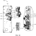
- Figs. 1A , 1B , 1C , and 1D disclose the device implementing the first charging and discharging mechanism for the ZVC spring.
- the device implementing the first charging and discharging mechanism may be referred hereinafter as a device 160.
- the device 106 comprises a ZVC 101, a ZVC plunger 103, a ZVC spring 102, a circuit breaking mechanism 108, a charging mechanism 130, and a discharging mechanism 140.
- the ZVC plunger 103 is arranged to be displaced between the charged position in which its held by a magnetic field generated by the ZVC 101, and a discharged position in which it is released by the ZVC 101.
- the ZVC spring 102 is connected to the ZVC plunger 103.
- the ZVC spring 102 is operable between a charged position corresponding to the charged position of the ZVC plunger and a discharged position corresponding to the discharged position of the ZVC plunger 103.
- the charging mechanism 130 is configured for displacing the ZVC spring 102 to its charged position.
- the charging mechanism 130 comprises a plural linkage mechanism configured to be connected in one end of the ZVC plunger 103 for enabling charging of the ZVC plunger 103 and of the ZVC spring 102 through a pivotation of at least one of links of the plural linkage mechanism.
- the charging mechanism 130 may comprise a rotary retention lever 109.
- the end referred herein may be an end of the plural linkage mechanism that is distant from the ZVC plunger 103.
- the rotation of the rotary retention lever 109 may cause a displacement of links of the plural linkage mechanism to a position in which the ZVC plunger 103 and the ZVC spring 102 are in their respective charged position and in which a spacing between at least two links of the plural linkage mechanism is present.
- the plural linkage mechanism of the charging mechanism 130 comprises a charging lever 110 and a cam element 112.
- the charging lever 110 un-releasably connected to cam via coupler 111.
- Cam releasably connected to plunger and to be releasably connected to the retention lever 109.
- the cam element 112 may be configured to be connected to the charging lever 110 by means of a coupler 111.
- the discharging mechanism 140 is configured to be connected to the ZVC plunger 103 and to be displaced by the ZVC spring 102 and the ZVC plunger 102 upon discharging of the ZVC spring 102, and the ZVC plunger 103 into a position in which it triggers the circuit breaking mechanism 108 to break the electrical circuit.
- the discharging mechanism comprises a plural linkage mechanism connected in one end to the ZVC plunger and in an opposite end with the circuit breaking mechanism 108.
- the discharging mechanism 140 comprises an L-bracket 102, a connection strip 105, and a bend bracket 106.
- the L-bracket 104 may be connected in one end to the ZVC plunger 103.
- the connection strip 105 may be connected to the L-bracket 104.
- the bend bracket 106 may be connected to the connection strip 105.
- the ZVC plunger 103 and the ZVC spring 102 When the ZVC plunger 103 and the ZVC spring 102 are in their respective charged position, there is a spacing between at least two links of the plural linkage mechanism of the charging mechanism 130, or between the charging mechanism 130 and the ZVC plunger 103 or between the charging mechanism 130 and any part of the discharging mechanism 140 via which the charging mechanism 130 is connected to the ZVC plunger 103.
- the spacing enables the ZVC plunger 103 to move from its charged position to its discharged position without being hindered by the charging mechanism 130. Thereby, to displace the discharging mechanism 140 to the position in which it triggers the circuit breaking mechanism 108 to break the electrical circuit.
- the ZVC spring 102 is in the discharged position.
- the ZVC spring 102 and the ZVC plunger 103 may be charged by the action of the charging mechanism 130.
- the retention lever 109 may be configured to rotate by exceeding a first pre-defined threshold for causing rotation of the charging lever 110 and for further causing rotation of the cam element 112 to displace the ZVC plunger 103 and the ZVC spring 102 to their respective charged position.
- the rotation of the retention lever 109 exceeding the first pre-defined threshold may be referred as an overtravel of the retention lever 109.
- the overtravel may be a variable parameter, which normally reduces with consecutive operations of the device 160.
- the overtravel may be dependent on a closing speed of the device 160. Higher the closing speed, higher will be the overtravel of the retention lever 109.
- the overtravel may also be a function of excess amount of energy available in a closing spring over an opening spring.
- the charging lever 110 comprises a spring 115 and a stopper pin 116.
- the spring 115 may be configured to rotate the charging lever 110, when the charging lever 110 crosses a first toggle position during charging of the ZVC spring 102 and the ZVC plunger 103 to their respective charged position by the action of the charging mechanism 130.
- the stopper pin 116 may be configured to stop rotation of the charging lever 110, when the charging lever 110 crosses a second toggle position during charging of the ZVC spring 102 and the ZVC plunger 103 to their respective charged position by the action of the charging mechanism 130.
- a profile of the cam element 112 may be designed in such a way that the cam element 112 would be able to charge the ZVC spring 102 at a minimum overtravel. Additionally, dwell may be provided on the cam element 112, so that it does not damage the ZVC 101 by causing dead-stop inside the ZVC 101 during a maximum overtravel.
- the cam element 112 comprises a pin 113 mounted on it.
- the pin 112 may be configured to slide inside a slot of a slotted lever 114 pivotally connected to the L-bracket 104, and the retention lever 109 may be configured to rotate further to a position in which said spacing exists between the retention lever 109 and the charging lever 110.
- disengagement of charging and discharging mechanism after charging of the ZVC spring 102 and the ZVC plunger 103 to their respective charged position may be advantageous, as it eliminates a need to test robustness of entire plural linkage mechanism of the charging mechanism 130 connected to the ZVC 101.
- the spring 115 on the charging lever 110 may show a tendency to rotate the charging lever 110 in a clockwise direction when the ZVC 101 is in a discharged condition.
- the spring 115 may show a tendency to rotate the charging lever 110 in an anticlockwise direction when and the charging lever 110 cross the first toggle position.
- the charging lever 110 may be stopped by the stopper pin 116 after crossing the second toggle position.
- the pin 113 on the cam element 112 may slide freely inside the slot of the slotted lever 114 during charging of the ZVC spring 102 and the ZVC plunger 103 to their respective charged position.
- the slotted lever 114 may have the slot such that at an end of charging of the ZVC spring 102 and the ZVC plunger 103 to their respective charged position, the pin 113 may touch an end of the slot of the slotted lever 114.
- the spacing/positive gap created between the retention lever 109 and the charging lever 110 ensures that the plural linkage mechanism of the charging mechanism may be operated only if the ZVC spring 102 and the ZVC plunger 103 are operated and as the ZVC 101 is operated for fewer operations compared to the device 106. Thus, eliminating a need to perform mechanical endurance test of the plural linkage mechanism of the charging mechanism 130.
- the device 160 in the closed position and the ZVC 101 (i.e., the ZVC spring 102 and the ZVC plunger 103) in the charged position with disengagement of the plural linkage mechanism of the charging mechanism 130 with the retention lever 109 is depicted in Fig. 1C .
- the plural linkage mechanism of the charging mechanism 130 Upon discharging of the ZVC spring 102, the plural linkage mechanism of the charging mechanism 130 has to restore its position as depicted in Fig. 1A .
- energy from the ZVC spring 102 may be utilized for two purposes.
- a first purpose is to disturb an equilibrium state of the circuit breaking mechanism 108 by the discharging mechanism 140, which may result in opening operation of the device 160.
- a second purpose is to reset the position of the charging mechanism 130, which may be achieved by the slotted lever 114, which pushes the pin 113 that causes rotation of the cam element 112 and ultimately the charging lever 110. This may cause the spring 115 to cross a toggle position, which may restore an initial configuration of the charging mechanism 130.
- the ZVC spring 102 in discharged position and the opening condition of the device 160 is depicted in Fig. 1D .
- Figs. 2A , 2B , and 2C disclose the device implementing the second charging and discharging mechanism for the ZVC spring.
- the device implementing the second charging and discharging mechanism may be referred hereinafter as a device 260.
- the device 260 comprises a ZVC 201, a ZVC plunger 203, a ZVC spring 202, a circuit breaking mechanism 208, a charging mechanism 230, and a discharging mechanism 240.
- the ZVC plunger 203 is arranged to be displaced between the charged position in which its held by a magnetic field generated by the ZVC 201, and a discharged position in which it is released by the ZVC 201.
- the ZVC spring 202 is connected to the ZVC plunger 203.
- the ZVC spring 202 is operable between a charged position corresponding to the charged position of the ZVC plunger 203 and a discharged position corresponding to the discharged position of the ZVC plunger 203.
- the charging mechanism 230 is configured to displace the ZVC spring 202 to its charged position.
- the charging mechanism 230 comprises a plural linkage mechanism configured to be connected in one end of the ZVC plunger 203 for enabling charging of the ZVC plunger 203 and of the ZVC spring 202 through a pivotation of at least one of links of the plural linkage mechanism.
- the charging mechanism 230 comprises the retention lever 209 and charging lever 210.
- the charging lever 210 may be configured to be connected to the plunger 203 with connection link 222 by lower pair and to retention lever 209 by higher pair.
- the discharging mechanism 240 is configured to be connected to the ZVC plunger 203 and to be displaced by the ZVC spring 202 and the ZVC plunger 203 upon discharging of the ZVC spring 202, and the ZVC plunger 203 into a position in which it triggers the circuit breaking mechanism 208 to break the electrical circuit.
- the discharging mechanism 240 comprises a plural linage mechanism connected in one end to the ZVC plunger 203 and in an opposite end with the circuit breaking mechanism 208.
- the plural linkage mechanism of the discharging mechanism 240 comprises a connection link 222, a connection strip 205, and a bend bracket 206.
- the connection link 222 may be connected in one end to the ZVC plunger 203.
- the connection strip 205 may be connected to the connection link 222.
- the bend bracket 206 may be connected to the connection strip 205 and to the circuit breaking mechanism 208.
- the charging lever 210 is connected to the ZVC plunger 203 via the connecting link 222.
- the ZVC plunger 203 and the ZVC spring 202 When the ZVC plunger 203 and the ZVC spring 202 are in their respective charged position, there is a spacing between at least two links of the plural linkage mechanism of the charging mechanism 230, or between the charging mechanism 230 and the ZVC plunger 203 or between the charging mechanism 230 and any part of the discharging mechanism 240 via which the charging mechanism 230 is connected to the ZVC plunger 203.
- the spacing enables the ZVC plunger 203 to move from its charged position to its discharged position without being hindered by the charging mechanism 230. Thereby, to displace the discharging mechanism 240 to the position in which it triggers the circuit breaking mechanism 208 to break the electrical circuit.
- the charging mechanism 230 may comprise the rotary retention lever 209.
- the end referred herein may be an end of the plural linkage mechanism that is distant from the ZVC plunger 203.
- the rotation of the rotary retention lever 209 may cause a displacement of the links of the plural linkage mechanism to a position in which the ZVC plunger 203 and the ZVC spring 202 are in their respective charged position and in which the spacing between at least two links of the plural linkage mechanism is present.
- the device 260 may be in the open position.
- a supply may be provided to the ZVC 201.
- an additional mechanism may be used to push the ZVC plunger 203 against the ZVC spring 202.
- the ZVC spring 202 and the ZVC plunger 203 may be charged to their respective charged position by the action of the charging mechanism 230.
- the retention lever 209 may be configured to rotate (in a counter clockwise direction) by exceeding the first pre-defined threshold. Rotation of the retention lever 209 exceeding the first pre-defined threshold may be referred as overtravel of the retention lever 209 or rotation of the retention lever 209 in an overtravel zone.
- Rotation of the retention lever 209 in the overtravel zone may cause rotation of the charging lever 210 to displace the ZVC plunger 203 and the ZVC spring 202 via the connection link 222 to their respective charged position.
- rotation of the charging lever 210 may cause the ZVC plunger 203 to start moving in an upward direction.
- the ZVC plunger 203 may be pulled and hold by the magnetic force generated by the ZVC 201.
- a profile on the retention lever 209 is such that even if the retention lever 209 rotates excess in the overtravel, it may not rotate the charging lever 210 after certain rotation, as depicted in Fig. 2C (i.e., the charging lever 210 may be in dwell condition).
- the retention lever 209 may start rotating back in an opposite direction and may be locked on the circuit breaking mechanism 208, as depicted in Fig. 2D .
- the retention lever 209 and the charging lever 210 may be spaced apart by the spacing. The said spacing may be required for discharging of the ZVC spring 202 and ultimately tripping the device 260.
- the ZVC 201 may lose its magnetic force and the ZVC spring 202 may be configured to displace the ZVC plunger 203 (in a downward direction) and the connection link 222 to which the charging lever 210 is connected. Thereby, causing rotation of the charging lever 210 back to a position in which it will be releasably connected by the retention lever 209 upon rotation of the retention lever 209 to the first pre-defined threshold during the subsequent charging operation.
- the charging lever 210 may be further configured to transfer motion to the bend bracket 206 through the connection link 205.
- the bend bracket 206 may rotate and hit a latch catch connected to the circuit breaking mechanism 208 to rotate it. Rotation of the latch catch disturbs an equilibrium state of the circuit breaking mechanism 209. Thereby, triggering the circuit breaking mechanism 208 to break the electrical circuit, as depicted in Fig. 2E .
- Figs. 3A , 3B , and 3C disclose the device implementing the third charging and discharging mechanism for the ZVC spring.
- the device implementing the third breaking mechanism may be referred hereinafter as a device 360.
- the device 360 comprises a ZVC 301, a ZVC plunger 303, a ZVC spring 302, a circuit breaking mechanism 308, a charging mechanism 330, and a discharging mechanism 340.
- the ZVC plunger 303 is arranged to be displaced between the charged position in which its held by a magnetic field generated by the ZVC 301, and a discharged position in which it is released by the ZVC 301.
- the ZVC spring 302 is connected to the ZVC plunger 303.
- the ZVC spring 302 is operable between a charged position corresponding to the charged position of the ZVC plunger 303 and a discharged position corresponding to the discharged position of the ZVC plunger 303.
- the charging mechanism 330 is configured to displace the ZVC spring 302 to its charged position.
- the charging mechanism 330 comprises a plural linkage mechanism configured to be connected in one end of the ZVC plunger 303 for enabling charging of the ZVC plunger 303 and of the ZVC spring 302 through a pivotation of at least one of links of the plural linkage mechanism.
- the discharging mechanism 340 is configured to be connected to the ZVC plunger 303 and to be displaced by the ZVC spring 302 and the ZVC plunger 303 upon discharging of the ZVC spring 302, and the ZVC plunger 303 into a position in which it triggers the circuit breaking mechanism 308 to break the electrical circuit.
- the discharging mechanism 340 comprises a plural linage mechanism connected in one end to the ZVC plunger 303 and in an opposite end with the circuit breaking mechanism 308.
- the ZVC plunger 303 and the ZVC spring 302 When the ZVC plunger 303 and the ZVC spring 302 are in their respective charged position, there is a spacing between at least two links of the plural linkage mechanism of the charging mechanism 330, or between the charging mechanism 330 and the ZVC plunger 303 or between the charging mechanism 330 and any part of the discharging mechanism 340 via which the charging mechanism 330 is connected to the ZVC plunger 303.
- the spacing enables the ZVC plunger 303 to move from its charged position to its discharged position without being hindered by the charging mechanism 330. Thereby, to displace the discharging mechanism 340 to the position in which it triggers the circuit breaking mechanism 308 to break the electrical circuit.
- the charging mechanism 330 may comprise a rotary retention lever 309.
- the end referred herein may be an end of the plural linkage mechanism that is distant from the ZVC plunger 303.
- the rotation of the rotary retention lever 309 may cause a displacement of the links of the plural linkage mechanism to a position in which the ZVC plunger 303 and the ZVC spring 302 are in their respective charged position and in which the spacing between at least two links of the plural linkage mechanism is present.
- the charging mechanism 330 comprises the retention lever 309, a coupler 311, and an oscillator 328.
- the coupler 311 may be connected to the retention lever 309.
- the oscillator 328 may be connected to the coupler 311.
- the discharging mechanism 340 comprises a connecting link 322, a charging link 324, a connection strip 305, and a bend bracket 326.
- the connecting link 322 may be connected in one end to the ZVC plunger 303.
- the charging link 324 may be connected to the connecting link 322.
- the connection strip 305 may be connected in one end to the charging link 324.
- the bend bracket 326 may be connected in one end to the connection strip 305 and in opposite end to the circuit breaking mechanism 308.
- the oscillator 328 may have a charging pin 327, which may be connectable to the charging link 324 and configured to push the charging link 324 upon a pre-determined rotation of the retention lever 309. Thereby inducing charging motion of the ZVC plunger 303 and the ZVC spring 302. After rotation of the retention lever 309 such that charging of the ZVC plunger 303 and the ZVC spring 302 is achieved, the retention lever 309 is configured to be rotated in an opposite direction such that said spacing is formed between the charging pin 327 and the charging link 324.
- the ZVC spring 302 and the ZVC plunger 303 may be charged to their respective charged position by the action of the charging mechanism 330.
- the retention lever 309 may be configured to displace the oscillator 328.
- the oscillator 328 may be configured to push the charging link 324 at an end of an opening stroke for enabling the charging link 324, the connection link 322, and the plunger 303 to displace the ZVC spring 302 and the ZVC plunger 303 to their respective charged position.
- the charging link 324, the connection strip 305, and the bend bracket 326 may be configured to move for bringing the circuit breaking mechanism 308 to a latched condition.
- the retention lever 309 may cause the oscillator 328 to rotate by a desired angle, which may create the spacing between the charging pin 327 and the charging link 324.
- the said spacing may be necessary for discharging of the ZVC spring 302/ZVC 301 without encountering the dead-stop.
- the ZVC spring 302 when the ZVC spring 302 moves to its discharged position during the tripping operation of the device 360, the ZVC spring 302 may be configured to transfer energy to a latch catch of the circuit breaking mechanism 308 by means of the discharging mechanism 340 for disturbing an equilibrium of the circuit breaking mechanism 308 and to further release the retention lever 309 from the circuit breaking mechanism 308.
- Figs. 4A , 4B , and 4C disclose the device implementing the fourth charging and discharging mechanism for the ZVC spring.
- the device implementing the fourth breaking mechanism may be referred hereinafter as a device 460.
- the device 460 comprises a ZVC 401, a ZVC plunger 403, a ZVC spring 402, a circuit breaking mechanism 408, a charging mechanism 430, and a discharging mechanism 440.
- the ZVC plunger 403 is arranged to be displaced between the charged position in which its held by a magnetic field generated by the ZVC 401, and a discharged position in which it is released by the ZVC 401.
- the ZVC spring 402 is connected to the ZVC plunger 403.
- the ZVC spring 402 is operable between a charged position corresponding to the charged position of the ZVC plunger 403 and a discharged position corresponding to the discharged position of the ZVC plunger 403.
- the charging mechanism 430 is configured to displace the ZVC spring 402 to its charged position.
- the charging mechanism 430 comprises a plural linkage mechanism configured to be connected in one end of the ZVC plunger 403 for enabling charging of the ZVC plunger 403 and of the ZVC spring 402 through a pivotation of at least one of links of the plural linkage mechanism.
- the discharging mechanism 440 is configured to be connected to the ZVC plunger 403 and to be displaced by the ZVC spring 402 and the ZVC plunger 402 upon discharging of the ZVC spring 402, and the ZVC plunger 403 into a position in which it triggers the circuit breaking mechanism 408 to break the electrical circuit.
- the discharging mechanism 440 comprises a plural linage mechanism connected in one end to the ZVC plunger 403 and in an opposite end with the circuit breaking mechanism 408.
- the ZVC plunger 403 and the ZVC spring 402 When the ZVC plunger 403 and the ZVC spring 402 are in their respective charged position, there is a spacing between at least two links of the plural linkage mechanism of the charging mechanism 430, or between the charging mechanism 430 and the ZVC plunger 403 or between the charging mechanism 430 and any part of the discharging mechanism 440 via which the charging mechanism 430 is connected to the ZVC plunger 403.
- the spacing enables the ZVC plunger 403 to move from its charged position to its discharged position without being hindered by the charging mechanism 430. Thereby, to displace the discharging mechanism 440 to the position in which it triggers the circuit breaking mechanism 408 to break the electrical circuit.
- the charging mechanism 430 may comprise a rotary retention lever 409.
- the end referred herein may be an end of the plural linkage mechanism that is distant from the ZVC plunger 403.
- the rotation of the rotary retention lever 409 may cause a displacement of the links of the plural linkage mechanism to a position in which the ZVC plunger 403 and the ZVC spring 402 are in their respective charged position and in which the spacing between at least two links of the plural linkage mechanism is present.
- the charging mechanism 430 comprises the retention lever 409 and a charging lever 410.
- the charging lever 410 may be spring-loaded such that it exerts a charging force on the ZVC plunger 403.
- the retention lever 409 may be configured to be rotated such that it counteracts the spring load on the charging lever 410. After charging of the ZVC plunger 403 and the ZVC spring 402 by the action of the charging lever 410, the retention lever 409 is configured to be rotated to a pre-determined angular position such that it pivots the charging lever 410 to a position in which the spacing is present between the charging lever 410 and the ZVC plunger 403. The retention lever 409 may be further configured to engage and close the circuit breaker mechanism 408 upon being rotated to the pre-determined angular position. Upon discharging of the ZVC spring 403/ZVC plunger 403, the discharging mechanism 440 may trigger an opening of the circuit breaker mechanism 408. Such an opening may trigger a rotation of the retention lever 409 to an angular position in which the retention lever does not engage the charging lever 410. Thereby, enabling the charging lever 410 to apply its spring force on the ZVC plunger 403 for the charging thereof.
- the charging mechanism 430 may also comprise a stop pin 443 (also be referred to as eccentric pin) along with the retention lever 409 and the charging lever 410.
- the charging lever 410 may be rotatably mounted on the stop pin 443. By rotating the stop pin 443 during the opening operation of the device 460, angular position of the charging lever 410 may be set.
- the stop pin 443 may be configured to prevent the charging lever 410 from pivoting beyond a point at which remaining motion of the ZVC plunger 403 to its charged position is enabled by application of a pre-determined voltage on the ZVC 401.
- the discharging mechanism 440 comprises an L-bracket 404, a connection strip 405, and a bend bracket 406.
- the connection strip 405 may be connected to the L-bracket 404.
- the bend bracket 406 may be connected to the connection strip 405 and to the circuit breaking mechanism 408.
- the device 460 further comprises a torsion spring 441 and a spring stopper pin 442.
- the torsion spring 441 may be configured to apply the spring load on the charging lever 410. Also, a position of the charging lever 410 may be secured by the torsion spring 441.
- the spring stopper pin 442 may be configured to support a fixed leg of the torsion spring 441.
- the charging lever 410 is configured to displace the ZVC plunger 403 by means of the torsion spring 441 for displacing the ZVC spring 402 and the ZVC plunger 403 to the respective charged position.
- the ZVC spring 402 may be charged by eliminating issues related to dependency on overtravel of the retention lever 409. Further, using the fourth charging and discharging mechanism, the device 460 may be tripped at increased friction and relaxed spring conditions.
- the retention lever 409 is configured to rotate and interact with the charging lever 410 for causing the charging lever 410 to rotate and disengage from the ZVC plunger 403.
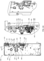
- the retention lever 409 may lock on the circuit breaking mechanism 408, as depicted in Fig. 4B .
- the ZVC plunger 403 may maintain its position due to magnetic pulling force of the ZVC 401, which may result in the spacing between the ZVC plunger 403 and the charging lever 410. The said spacing may be essential during tripping operation of the device 460 using the ZVC 401.
- the ZVC spring 402 starts discharging.
- the ZVC spring 402 may be configured to displace the ZVC plunger 403 in a downward direction.
- the downward motion of the ZVC plunger 403 may be transferred to a latch catch of the circuit breaking mechanism 408 using the discharging mechanism 440. Due to the movement of the latch catch, the equilibrium of the circuit breaking mechanism 408 may be disturbed and may result in tripping of the device 460.
- the retention lever 409 may rotate in a clockwise direction and the charging lever 410 may rotate in a counter clockwise direction to push the ZVC plunger 403 in the upward direction for enabling the ZVC spring 402 to move towards the charged position, as depicted in Fig. 4C .
- the device 460 further comprises a blockage assembly 432, and a micro switch 435.
- the blockage assembly 432 comprises a threaded bush 433, which may be configured to lock the ZVC plunger 403 in a lock condition using a bolt 431 for mechanically blocking the ZVC spring 402.
- the micro switch 435 may be configured to provide an alert indicating that the ZVC spring 402 is being blocked manually.
- the device 460 further comprises a holder 436, a latch link 437, and a latch torsion spring 438.
- the holder 436 may be configured to be mounted on the circuit breaking mechanism 408.
- the latch link 437 may be configured to be assembled on the holder 436 using a pin 439.
- the latch torsion spring 438 may be configured to be arranged between the holder 436 and the latch link 437 and over the pin 439.
- the latch link 437 may be operated against a torque of the latch torsion spring 438 for manually tripping of the device 460.
- all the charging and discharging mechanisms implemented by the device may be designed by considering one or more of: no dependency on open orientation of a retention lever of the charging mechanism, a minimum number of links in the charging mechanism, minimum horizontal force on the ZVC plunger, and high margin for force available to trip/break the device.
- the ZVC spring may be charged without any failure.
Landscapes
- Mechanisms For Operating Contacts (AREA)
Abstract
Description
- The present disclosure generally relates to circuit breaker drive mechanisms. More particularly, it relates to providing multiple charging and discharging mechanisms for a zero volt coil, ZVC, spring in a circuit breaker.
- Protection systems that include logic circuits, sensors, relays, circuit breakers, fuses, isolators, instrument transformers, and other protection devices, are provided in electrical power systems to control, protect and isolate electrical equipment of the electrical power systems during any electrical fault. The electrical fault may correspond to an abnormal condition in the electrical power system, which may damage the electrical equipment and disturb normal flow of electric current in the electrical power system. The electrical fault may occur in one or more of three phases or a power line of the electrical power system.
- During an electrical fault, an Intelligent Electronic Device, IED, provided in the electrical power system may sense occurrence of the electrical fault. Thereafter, the lED may cause operation of a circuit breaker to protect an electrical circuit from damage that may be caused due to the electrical fault. For example, the electrical fault may occur due to an overload or a short circuit in the power line in the electrical power system. In response to detection of the electrical fault by the IED, the circuit breaker may interrupt current flow in the power line. Once the electrical fault is cleared, the circuit breaker may be reset or closed to resume normal operation of the power line and the power system, either manually or automatically. To this end, sufficient mechanical power/potential energy is required during an opening operation and a closing operation of the circuit breaker.
- Moreover, the potential energy required for opening and closing operations of the circuit breaker may be provided by an operating mechanism, such as a spring operating mechanism/circuit breaking mechanism. The spring operating mechanism may have potential energy mechanically stored in springs. For example, different spring operating mechanisms, such as BLK, BLG, MSD, and FSA, may be used based on a rating of the power line to be isolated or a rating of the circuit breaker.
- Initially, a Zero Volt Coil, ZVC, solution was developed to adapt FSA-ZVC for BLK open latch application in FSA1+ I Drive. In ZVC solution, the circuit breaker comprises a ZVC, a ZVC plunger connected to the ZVC, and a ZVC spring connected to the ZVC plunger. Available FSA-ZVC based spring operating mechanism of the circuit breaker requires additional components/devices such as resistor, timer, contactor, under voltage relay, and so on, to satisfy International Organization for Standardization/International Electro technical Commission, IEC, requirements of tripping the circuit breaker below specified percentage of rated voltage.
- However, some customers may require ZVC solution without additional components. From feasibility studies, it was evident that FSA-ZVC is non-suitable for such requirements. On the other hand, BLK-ZVC satisfies customer requirements without additional components. Further, BLK-ZVC requires external force to charge the ZVC spring, whereas FSA-ZVC has inbuilt capacity to charge the spring.
- Consequently, there is a need for charging and discharging mechanisms for a ZVC spring in a device/circuit breaker that alleviates at least some of the above-cited problems.
- It is therefore an object of the present disclosure to provide a device for an electrical circuit, which implements multiple charging and discharging mechanisms for a ZVC spring, to mitigate, alleviate, or eliminate all or at least some of the above-discussed drawbacks of presently known solutions.
- This and other objects are achieved by means of a device, as defined in the appended claims. The term exemplary is in the present context to be understood as serving as an instance, example or illustration.
- According to a first aspect of the present disclosure, a device for an electrical circuit is provided. The device comprises a zero-volt coil, ZVC. The device comprises a ZVC plunger, which is arranged to be displaced between a charged position in which it is held by a magnetic field generated by the ZVC and a discharged position in which it is released by the ZVC. The device comprises a ZVC spring connected to the ZVC plunger. The ZVC spring is operable between a charged position corresponding to the charged position of the ZVC plunger and a discharged position corresponding to the discharged position of the ZVC plunger. The device comprises a circuit breaking mechanism. The device comprises a charging mechanism for displacing the ZVC spring to its charged position. The device comprises a discharging mechanism configured to be connected to the ZVC plunger and to be displaced by the ZVC spring and the ZVC plunger upon discharging of the ZVC spring and the ZVC plunger into a position in which it triggers the circuit breaking mechanism to break the electrical circuit. The charging mechanism comprises a plural linkage mechanism configured to be connected in one end to the ZVC plunger for enabling charging of the ZVC plunger and of the ZVC spring through a pivotation of at least one of the links of the plural linkage mechanism. The discharging mechanism comprises a plural linkage mechanism connected in one end to the ZVC plunger and in an opposite end with the circuit breaking mechanism. When the ZVC plunger and the ZVC spring are in their respective charged position, there is a spacing between at least two links of the plural linkage mechanism of the charging mechanism or between the charging mechanism and the ZVC plunger or between the charging mechanism and any part of the discharging mechanism via which the charging mechanism is connected to the ZVC plunger, which spacing enables the ZVC plunger to move from its charged position to its discharged position without being hindered by the charging mechanism and thereby to displace the discharging mechanism to the position in which it triggers the circuit breaking mechanism to break the electrical circuit.
- The ZVC plunger is arranged to be displaced between the charged position and the discharged position as a result of a predetermined voltage reduction in the ZVC and displaced relative to the charged position.
- When in its charged position, the ZVC spring exerts a force on the ZVC plunger in a direction in which it strives at forcing the ZVC plunger in a direction away from its charged position, in which the ZVC plunger is held by the ZVC upon application of a voltage onto the ZVC towards the discharged position of the ZVC plunger, such that, upon application of the predetermined reduced voltage on the ZVC. The ZVC plunger is moved in said direction by the action of the ZVC spring to adapt its discharged position, for the purpose of initiating circuit breaking by the device.
- In some embodiments, at an end of the plural linkage mechanism of the charging mechanism, which end is an end of the plural linkage mechanism, which is distant from the ZVC plunger. The charging mechanism comprises a rotary retention lever, wherein a rotation of the retention lever causes a displacement of the links of the plural linkage mechanism to a position in which the ZVC plunger and the ZVC spring are in their respective charged position and in which said spacing between at least two links of the plural linkage mechanism is present.
- Thus, the device disclosed herein implements charging and discharging mechanisms for charging the ZVC spring and for disengaging the plural linkage mechanism of the charging mechanism, thereby breaking the electrical circuit. Advantageously, using the charging and discharging mechanisms implemented by the device, the ZVC spring may be charged during opening or closing operation of the device.
- Further, the charging and discharging mechanisms implemented by the device may be designed by considering one or more of: no dependency on open orientation of a charging lever of the charging mechanism, a minimum number of links in the charging mechanism, minimum horizontal force on the ZVC plunger, and high margin for force available to trip/break the device.
- In some embodiments, the plural linkage mechanism of the charging mechanism comprises a charging lever configured to be connected to the ZVC plunger and to be releasably connected to the retention lever and a cam element configured to be connected to the charging lever by means of a coupler. The discharging mechanism comprises an L-bracket connected in one end to the ZVC plunger, a connection strip connected to the L-bracket, and a bend bracket connected to the connection strip.
- In some embodiments, during charging of the ZVC spring and the ZVC plunger to their respective charged position by the action of the charging mechanism, the retention lever is configured to rotate by exceeding a first pre-defined threshold for causing rotation of the charging lever and for further causing rotation of the cam element to displace the ZVC plunger and the ZVC spring to their respective charged position.
- In some embodiments, the charging lever comprises a spring configured to rotate the charging lever, when the charging lever crosses a first toggle positon during charging of the ZVC spring and the ZVC plunger to their respective charged position by the action of the charging mechanism and a stopper pin configured to stop rotation of the charging lever, when the charging lever crosses a second toggle position during charging of the ZVC spring and the ZVC plunger to their respective charged position by the action of the charging mechanism.
- In some embodiments, when the ZVC spring is being operated to the charged position by operation of the charging mechanism, a pin mounted on the cam element is configured to slide inside a slot of a slotted lever pivotally connected to the L-bracket, and the retention lever is configured to rotate further to a position in which said spacing exists between the retention lever and the charging lever.
- In some embodiments, upon discharging of the ZVC spring, the discharging mechanism is configured to disturb an equilibrium state of the circuit breaking mechanism and the slotted lever is configured to cause rotation of the cam element and the charging lever.
- In some embodiments, the charging mechanism comprises a retention lever and a charging lever configured to be connected to the ZVC plunger and to be releasably connected to the retention lever. The discharging mechanism comprises a connection link connected in one end to the ZVC plunger, a connection strip connected to the connection link, and a bend bracket connected to the connection strip and to the circuit breaking mechanism, and wherein the charging lever is connected to the ZVC plunger via the connecting link.
- In some embodiments, during charging of the ZVC spring and the ZVC plunger to their respective charged position by the action of the charging mechanism, the retention lever is configured to rotate by exceeding a first pre-defined threshold for causing rotation of the charging lever to displace the ZVC plunger and the ZVC spring via the connection link to their respective charged position.
- In some embodiments, during charging of the ZVC spring and the ZVC plunger to their respective charged position by the action of the charging mechanism by a rotation of the retention lever, the retention lever is configured to rotate back in an opposite direction such that, when the ZVC spring is in the charged position, the retention lever and the charging lever are spaced apart by said spacing.
- In some embodiments, wherein, during discharge of the ZVC spring, the ZVC spring is configured to displace the plunger and the connection link, to which the charging lever is connected, and thereby causing rotation of the charging lever back to a position in which it will be releasably connected by the retention lever upon rotation of the retention lever to said first threshold during a subsequent charging operation, and to further cause the bend bracket to disturb an equilibrium state of the circuit breaking mechanism and thereby trigger the circuit breaking mechanism to break an electric circuit.
- In some embodiments, the charging mechanism comprises a retention lever, a coupler connected to the retention lever, and an oscillator connected to the coupler. The discharging mechanism comprises a connecting link connected in one end to the ZVC plunger, a charging link connected to the connecting link, and a connection strip connected in one end to the charging link, and a bend bracket connected in one end to the connection strip and in an opposite end to the circuit breaking mechanism. The oscillator has a charging pin, which is connectable to the charging link and configured to push the charging link upon a predetermined rotation of the retention lever and thereby induce charging motion of the ZVC plunger and the ZVC spring and wherein, after rotation of the retention lever such that charging of the ZVC plunger and ZVC spring is achieved, the retention lever is configured to be rotated in an opposite direction such that said spacing is formed between said charging pin and the charging link.
- In some embodiments, during charging of the ZVC spring and the ZVC plunger to their respective charged position by the action of the charging mechanism, the retention lever is configured to displace the oscillator, which is configured to push the charging link at an end of an opening stroke for enabling the charging link, the connecting link, and the ZVC plunger to displace the ZVC spring and the ZVC plunger to their respective charged position.
- In some embodiments, wherein, during charging of the ZVC spring and the ZVC plunger, the charging link, the connection strip, and the bend bracket are configured to move for bringing the circuit breaking mechanism to a latched condition.
- In some embodiments, the charging mechanism comprises a charging lever, which is spring-loaded such that it exerts a charging force on the ZVC plunger and wherein the charging mechanism comprises a retention lever, which is configured to be rotated such that it counteracts the spring load on the charging lever, and wherein, after charging of the ZVC plunger and the ZVC spring by the action of the charging lever, the retention lever is configured to be rotated to a predetermined angular position such that it pivots the charging lever to a position in which said spacing is present between the charging lever and the ZVC plunger.
- In some embodiments, the charging mechanism comprises a charging lever which is spring-loaded such that it exerts a charging force on the ZVC plunger, and wherein the charging mechanism comprises a retention lever which is configured to be rotated such that it counteracts the spring load on the charging lever, and wherein, after charging of the ZVC plunger and the ZVC spring by the action of the charging lever the retention lever is configured to be rotated to a predetermined angular position such that it pivots the charging lever to a position in which said spacing is present between the charging lever and the ZVC plunger.
- In some embodiments, the retention lever is configured to engage and close the circuit breaker mechanism upon being rotated to said predetermined angular position, and wherein, upon discharging of the ZVC plunger, the discharging mechanism will trigger an opening of the circuit breaker mechanism, which opening will trigger a rotation of the retention lever to an angular position in which the retention lever does not engage the charging lever, thereby enabling the charging lever to apply its spring force on the ZVC plunger for the charging thereof.
- In some embodiments, the charging mechanism comprises the retention lever and the charging lever, and a stop pin, wherein the stop pin is configured to prevent the charging lever from pivoting beyond a point at which remaining motion of the ZVC plunger to its charged position is enabled by application of a predetermined voltage on the ZVC. The discharging mechanism comprises an L-bracket, a connection strip connected to the L-bracket and a bend bracket connected to the connection strip and to the circuit breaking mechanism.
- In some embodiments, the device further comprises a torsion spring configured to apply said spring load on the charging lever, and a spring stopper pin configured to support a fixed leg of the torsion spring.
- In some embodiments, during the opening operation of the device, and charging of the ZVC spring and the ZVC plunger, the charging lever is configured to displace the ZVC plunger by means of the torsion spring for displacing the ZVC spring and the ZVC plunger to their respective charged position.
- In some embodiments, during the closing operation of the device and the charging of the ZVC spring, the retention lever is configured to rotate and interact with the charging lever for causing the charging lever to rotate and disengage from the ZVC plunger, wherein when the ZVC spring is in the charged position, the retention lever is configured to lock on the circuit breaker mechanism.
- In some embodiments, wherein, when the ZVC spring moves to its discharged position during the closing operation of the circuit breaker, the ZVC spring is configured to transfer energy to a latch catch of the circuit breaking mechanism by means of the discharging mechanism and the charging mechanism for disturbing an equilibrium of the circuit breaking mechanism and to further release the retention lever from the circuit breaking mechanism.
- In some embodiments, when the circuit breaker is being operated from the closing operation to the opening operation, the ZVC spring is configured to displace the plunger for discharging mechanism to disturb an equilibrium of the circuit breaker mechanism for tripping of the circuit breaker.
- In some embodiments, when the circuit breaker is being tripped, the retention lever is configured to rotate for causing rotation of the charging lever to displace the plunger for enabling the ZVC spring to move towards the charged position.
- In some embodiments, the circuit breaker further comprises a blockage assembly comprising a threaded bush and is configured to lock the plunger in a locked condition using a bolt for mechanically blocking the ZVC spring and a microswitch configured to provide an alert indicating that the ZVC spring is being blocked.
- In some embodiments, wherein the circuit breaker further comprises: a holder configured to be mounted on the latch shaft, a latch link configured to be assembled on the holder using a pin, a latch torsion spring configured to be arranged between the holder and the latch link and over the pin. The latch link is operated against a torque of the latch torsion spring for manually tripping the circuit breaker.
- In some embodiments, any of the above aspects may additionally have features identical with or corresponding to any of the various features as explained above for any of the other aspects.
- Other advantages may be readily apparent to one having skill in the art. Certain embodiments may have some, or all of the recited advantages.
- The foregoing will be apparent from the following more particular description of the example embodiments, as illustrated in the accompanying drawings in which like reference characters refer to the same parts throughout the different views. The drawings are not necessarily to scale, emphasis instead being placed upon illustrating the example embodiments.
-
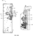
Figs. 1A ,1B ,1C , and1D disclose an example device for an electrical circuit implementing a first charging and discharging mechanism for a zero volt coil, ZVC, spring according to some embodiments; -
Figs. 2A ,2B ,2C ,2D , and2E disclose an example device for an electrical circuit implementing a second charging and discharging mechanism for a ZVC spring according to some embodiments; -
Figs. 3A ,3B , and3C disclose an example device for an electrical circuit implementing a third charging and discharging mechanism for a ZVC spring according to some embodiments; and -
Figs. 4A ,4B , and4C disclose an example device for an electrical circuit implementing a fourth charging and discharging mechanism for a ZVC spring according to some embodiments. - Aspects of the present disclosure will be described more fully hereinafter with reference to the accompanying drawings. The apparatus and methods disclosed herein can, however, be realized in many different forms and should not be construed as being limited to the aspects set forth herein. Like numbers in the drawings refer to like elements throughout.
- The terminology used herein is for the purpose of describing particular aspects of the disclosure only and is not intended to limit the invention. It should be emphasized that the term "comprises/comprising" when used in this specification is taken to specify the presence of stated features, integers, steps, or components, but does not preclude the presence or addition of one or more other features, integers, steps, components, or groups thereof. As used herein, the singular forms "a", "an" and "the" are intended to include the plural forms as well, unless the context clearly indicates otherwise.
- Embodiments herein disclose a device for an electrical circuit. The device referred herein may be a circuit breaker or a switching device, configured to be operated manually and/or automatically for controlling and protecting the electrical circuit (also be referred to as electrical equipment) of an electrical power system. For example, the device may operate to, for example, control opening and/or closing of the electrical circuit (specifically, a power line) to control flow of current through the circuit. As would be understood, the device may be provided at terminals of the power line for de-energization of a fault circuit or a faulty power line. In some examples, the device referred herein may be a high voltage circuit breaker.
- On detecting high fault current, an Intelligent Electronic Device, IED, may send an opening signal to the device. On receiving the opening signal, the device may interrupt current flow in the power line. Once the fault is cleared, the device may be reset or closed to resume normal operation of the power line and the electrical power system, either manually or automatically. A sufficient mechanical power/potential energy is required for the opening and closing operation of the device. The required potential energy for the opening and closing operation of the device may be provided by a spring operating mechanism. In some examples, the spring operating mechanism may be BLK.
- In embodiments disclosed herein, the device being operated in accordance with BLK comprises a zero volt coil, ZVC, spring coupled to a ZVC through a ZVC plunger. BLK-ZVC based spring operating mechanism of the device satisfy International Organization for Standardization/International Electro technical Commission, IEC, requirements of tripping the device below specified percentage of rated voltage without additional components such as resistor, timer, contactor, under voltage relay, and so on. BLK-ZVC charges the ZVC spring through an external force. Thus, there is a need for a charging and discharging mechanism for the ZVC spring in the device.
- Therefore, according to embodiments of the present disclosure, the device implements or triggers one of multiple (for example, first, second, third, fourth) charging and discharging mechanisms for efficient charging of the ZVC spring and for disengaging a charging mechanism configured for displacing the ZVC spring to its charged position. In first and second charging and discharging mechanisms, the ZVC spring is charged during a closing operation of the device. In third and fourth charging and discharging mechanisms, the ZVC spring is charged during an opening operation of the device.
- The device configured for implementing multiple charging and discharging mechanisms comprises a ZVC, a ZVC plunger, a ZVC spring, a circuit breaking mechanism, a charging mechanism, and a discharging mechanism.
- The ZVC plunger is arranged to be displaced between a charged position and a discharged position. In the charged position, the ZVC plunger is held by a magnetic field generated by the ZVC. In the discharged position, the ZVC plunger is released by the ZVC as a result of a predetermined voltage reduction in the ZVC and displaced relative to the charged position.
- The ZVC spring is connected to the ZVC plunger. The ZVC spring is operable between a charged position corresponding to the charged position of the ZVC plunger and a discharged position corresponding to the discharged position of the ZVC plunger. In its charged position, the ZVC spring exerts a force on the ZVC plunger in a direction in which it strives at forcing the ZVC plunger in a direction away from its charged position in which the ZVC plunger is held by the ZVC upon application of a voltage onto the ZVC. Towards the discharged position of the ZVC plunger, such that, upon application of the predetermined reduced voltage on the ZVC, the ZVC plunger is moved in said direction by the action of the ZVC spring to adapt its discharged position for the purpose of initiating a circuit breaking by the device.
- The charging mechanism is configured for displacing the ZVC spring to its charged position. The discharging mechanism is configured to be connected to the ZVC plunger and to be displaced by the ZVC spring and the ZVC plunger upon discharging of the ZVC spring and the ZVC plunger into a position in which it triggers the circuit breaking mechanism to break the electrical circuit.
- The charging mechanism comprises a plural linkage mechanism configured to be connected in one end to the ZVC plunger for enabling charging of the ZVC plunger and of the ZVC spring through a pivotation of at least one of links of the plural linkage mechanism. The discharging mechanism comprises a plural linkage mechanism connected in one end to the ZVC plunger and in an opposite end with the discharging mechanism.
- When the ZVC plunger and the ZVC spring are in their respective charged position, there is a spacing between at least two links of the plural linkage mechanism of the charging mechanism or between the charging mechanism and the ZVC plunger or between the charging mechanism and any part of the discharging mechanism via which the charging mechanism is connected to the ZVC plunger. The spacing enables the ZVC plunger to move from its charged position to its discharged position without being hindered by the charging mechanism, and thereby to displace the discharging mechanism to the position in which it triggers the circuit breaking mechanism to break the electrical circuit.
- Various embodiments describing the multiple charging and discharging mechanisms implemented by the device are explained in conjunction with figures in the later parts of the description.
-
Figs. 1A ,1B ,1C , and1D disclose the device implementing the first charging and discharging mechanism for the ZVC spring. The device implementing the first charging and discharging mechanism may be referred hereinafter as adevice 160. Thedevice 106 comprises aZVC 101, aZVC plunger 103, aZVC spring 102, acircuit breaking mechanism 108, acharging mechanism 130, and a dischargingmechanism 140. - The
ZVC plunger 103 is arranged to be displaced between the charged position in which its held by a magnetic field generated by theZVC 101, and a discharged position in which it is released by theZVC 101. - The
ZVC spring 102 is connected to theZVC plunger 103. TheZVC spring 102 is operable between a charged position corresponding to the charged position of the ZVC plunger and a discharged position corresponding to the discharged position of theZVC plunger 103. - The
charging mechanism 130 is configured for displacing theZVC spring 102 to its charged position. Thecharging mechanism 130 comprises a plural linkage mechanism configured to be connected in one end of theZVC plunger 103 for enabling charging of theZVC plunger 103 and of theZVC spring 102 through a pivotation of at least one of links of the plural linkage mechanism. At an end of the plural linkage mechanism of thecharging mechanism 130, thecharging mechanism 130 may comprise arotary retention lever 109. The end referred herein may be an end of the plural linkage mechanism that is distant from theZVC plunger 103. The rotation of therotary retention lever 109 may cause a displacement of links of the plural linkage mechanism to a position in which theZVC plunger 103 and theZVC spring 102 are in their respective charged position and in which a spacing between at least two links of the plural linkage mechanism is present. - More specifically, as depicted in
Figs. 1A-1D , the plural linkage mechanism of thecharging mechanism 130 comprises a charginglever 110 and acam element 112. The charginglever 110 un-releasably connected to cam viacoupler 111. Cam releasably connected to plunger and to be releasably connected to theretention lever 109. Thecam element 112 may be configured to be connected to the charginglever 110 by means of acoupler 111. - The discharging
mechanism 140 is configured to be connected to theZVC plunger 103 and to be displaced by theZVC spring 102 and theZVC plunger 102 upon discharging of theZVC spring 102, and theZVC plunger 103 into a position in which it triggers thecircuit breaking mechanism 108 to break the electrical circuit. The discharging mechanism comprises a plural linkage mechanism connected in one end to the ZVC plunger and in an opposite end with thecircuit breaking mechanism 108. - More specifically, as depicted in
Figs. 1A-1D , the dischargingmechanism 140 comprises an L-bracket 102, aconnection strip 105, and abend bracket 106. The L-bracket 104 may be connected in one end to theZVC plunger 103. Theconnection strip 105 may be connected to the L-bracket 104. Thebend bracket 106 may be connected to theconnection strip 105. - When the
ZVC plunger 103 and theZVC spring 102 are in their respective charged position, there is a spacing between at least two links of the plural linkage mechanism of thecharging mechanism 130, or between thecharging mechanism 130 and theZVC plunger 103 or between thecharging mechanism 130 and any part of the dischargingmechanism 140 via which thecharging mechanism 130 is connected to theZVC plunger 103. The spacing enables theZVC plunger 103 to move from its charged position to its discharged position without being hindered by thecharging mechanism 130. Thereby, to displace the dischargingmechanism 140 to the position in which it triggers thecircuit breaking mechanism 108 to break the electrical circuit. - As depicted in
Fig. 1A , during an open condition of thedevice 160, theZVC spring 102 is in the discharged position. - When the
device 160 undergoes closed operation/condition, as depicted inFig. 1B , theZVC spring 102 and theZVC plunger 103 may be charged by the action of thecharging mechanism 130. During charging of theZVC spring 102 and theZVC plunger 103 to their respective charged position by the action of thecharging mechanism 130, theretention lever 109 may be configured to rotate by exceeding a first pre-defined threshold for causing rotation of the charginglever 110 and for further causing rotation of thecam element 112 to displace theZVC plunger 103 and theZVC spring 102 to their respective charged position. - The rotation of the
retention lever 109 exceeding the first pre-defined threshold may be referred as an overtravel of theretention lever 109. The overtravel may be a variable parameter, which normally reduces with consecutive operations of thedevice 160. The overtravel may be dependent on a closing speed of thedevice 160. Higher the closing speed, higher will be the overtravel of theretention lever 109. The overtravel may also be a function of excess amount of energy available in a closing spring over an opening spring. - In some examples, the charging
lever 110 comprises aspring 115 and astopper pin 116. Thespring 115 may be configured to rotate the charginglever 110, when the charginglever 110 crosses a first toggle position during charging of theZVC spring 102 and theZVC plunger 103 to their respective charged position by the action of thecharging mechanism 130. Thestopper pin 116 may be configured to stop rotation of the charginglever 110, when the charginglever 110 crosses a second toggle position during charging of theZVC spring 102 and theZVC plunger 103 to their respective charged position by the action of thecharging mechanism 130. - In some examples, a profile of the
cam element 112 may be designed in such a way that thecam element 112 would be able to charge theZVC spring 102 at a minimum overtravel. Additionally, dwell may be provided on thecam element 112, so that it does not damage theZVC 101 by causing dead-stop inside theZVC 101 during a maximum overtravel. - In some examples, the
cam element 112 comprises apin 113 mounted on it. When theZVC spring 102 is being operated to the charged position by operation of thecharging mechanism 130, thepin 112 may be configured to slide inside a slot of a slottedlever 114 pivotally connected to the L-bracket 104, and theretention lever 109 may be configured to rotate further to a position in which said spacing exists between theretention lever 109 and the charginglever 110. - In some examples, disengagement of charging and discharging mechanism after charging of the
ZVC spring 102 and theZVC plunger 103 to their respective charged position may be advantageous, as it eliminates a need to test robustness of entire plural linkage mechanism of thecharging mechanism 130 connected to theZVC 101. To achieve such a disengagement, thespring 115 on the charginglever 110 may show a tendency to rotate the charginglever 110 in a clockwise direction when theZVC 101 is in a discharged condition. Upon minimum overtravel of theretention lever 109, thespring 115 may show a tendency to rotate the charginglever 110 in an anticlockwise direction when and the charginglever 110 cross the first toggle position. The charginglever 110 may be stopped by thestopper pin 116 after crossing the second toggle position. Thepin 113 on thecam element 112 may slide freely inside the slot of the slottedlever 114 during charging of theZVC spring 102 and theZVC plunger 103 to their respective charged position. The slottedlever 114 may have the slot such that at an end of charging of theZVC spring 102 and theZVC plunger 103 to their respective charged position, thepin 113 may touch an end of the slot of the slottedlever 114. When theretention lever 109 attains a close position and theZVC spring 102 and theZVC plunger 103 are charged to their respective charged position, the spacing is created between theretention lever 109 and the charginglever 110. The spacing/positive gap created between theretention lever 109 and the charginglever 110 ensures that the plural linkage mechanism of the charging mechanism may be operated only if theZVC spring 102 and theZVC plunger 103 are operated and as theZVC 101 is operated for fewer operations compared to thedevice 106. Thus, eliminating a need to perform mechanical endurance test of the plural linkage mechanism of thecharging mechanism 130. Thedevice 160 in the closed position and the ZVC 101 (i.e., theZVC spring 102 and the ZVC plunger 103) in the charged position with disengagement of the plural linkage mechanism of thecharging mechanism 130 with theretention lever 109 is depicted inFig. 1C . - Upon discharging of the
ZVC spring 102, the plural linkage mechanism of thecharging mechanism 130 has to restore its position as depicted inFig. 1A . When power is cut-off that is upon discharging of theZVC spring 102, energy from theZVC spring 102 may be utilized for two purposes. A first purpose is to disturb an equilibrium state of thecircuit breaking mechanism 108 by the dischargingmechanism 140, which may result in opening operation of thedevice 160. A second purpose is to reset the position of thecharging mechanism 130, which may be achieved by the slottedlever 114, which pushes thepin 113 that causes rotation of thecam element 112 and ultimately the charginglever 110. This may cause thespring 115 to cross a toggle position, which may restore an initial configuration of thecharging mechanism 130. TheZVC spring 102 in discharged position and the opening condition of thedevice 160 is depicted inFig. 1D . -
Figs. 2A ,2B , and2C disclose the device implementing the second charging and discharging mechanism for the ZVC spring. The device implementing the second charging and discharging mechanism may be referred hereinafter as adevice 260. Thedevice 260 comprises aZVC 201, aZVC plunger 203, aZVC spring 202, acircuit breaking mechanism 208, acharging mechanism 230, and a dischargingmechanism 240. - The
ZVC plunger 203 is arranged to be displaced between the charged position in which its held by a magnetic field generated by theZVC 201, and a discharged position in which it is released by theZVC 201. - The
ZVC spring 202 is connected to theZVC plunger 203. TheZVC spring 202 is operable between a charged position corresponding to the charged position of theZVC plunger 203 and a discharged position corresponding to the discharged position of theZVC plunger 203. - The
charging mechanism 230 is configured to displace theZVC spring 202 to its charged position. Thecharging mechanism 230 comprises a plural linkage mechanism configured to be connected in one end of theZVC plunger 203 for enabling charging of theZVC plunger 203 and of theZVC spring 202 through a pivotation of at least one of links of the plural linkage mechanism. Thecharging mechanism 230 comprises theretention lever 209 and charginglever 210. The charginglever 210 may be configured to be connected to theplunger 203 withconnection link 222 by lower pair and toretention lever 209 by higher pair. - The discharging
mechanism 240 is configured to be connected to theZVC plunger 203 and to be displaced by theZVC spring 202 and theZVC plunger 203 upon discharging of theZVC spring 202, and theZVC plunger 203 into a position in which it triggers thecircuit breaking mechanism 208 to break the electrical circuit. The dischargingmechanism 240 comprises a plural linage mechanism connected in one end to theZVC plunger 203 and in an opposite end with thecircuit breaking mechanism 208. - The plural linkage mechanism of the discharging
mechanism 240 comprises aconnection link 222, aconnection strip 205, and abend bracket 206. Theconnection link 222 may be connected in one end to theZVC plunger 203. Theconnection strip 205 may be connected to theconnection link 222. Thebend bracket 206 may be connected to theconnection strip 205 and to thecircuit breaking mechanism 208. The charginglever 210 is connected to theZVC plunger 203 via the connectinglink 222. - When the
ZVC plunger 203 and theZVC spring 202 are in their respective charged position, there is a spacing between at least two links of the plural linkage mechanism of thecharging mechanism 230, or between thecharging mechanism 230 and theZVC plunger 203 or between thecharging mechanism 230 and any part of the dischargingmechanism 240 via which thecharging mechanism 230 is connected to theZVC plunger 203. The spacing enables theZVC plunger 203 to move from its charged position to its discharged position without being hindered by thecharging mechanism 230. Thereby, to displace the dischargingmechanism 240 to the position in which it triggers thecircuit breaking mechanism 208 to break the electrical circuit. - At an end of the plural linkage mechanism of the
charging mechanism 230, thecharging mechanism 230 may comprise therotary retention lever 209. The end referred herein may be an end of the plural linkage mechanism that is distant from theZVC plunger 203. The rotation of therotary retention lever 209 may cause a displacement of the links of the plural linkage mechanism to a position in which theZVC plunger 203 and theZVC spring 202 are in their respective charged position and in which the spacing between at least two links of the plural linkage mechanism is present. - As depicted in
Fig. 2A , initially thedevice 260 may be in the open position. A supply may be provided to theZVC 201. As there is no self-picking up capacity in theZVC 201, an additional mechanism may be used to push theZVC plunger 203 against theZVC spring 202. - As depicted in
Fig. 2B , when the closing operation of thedevice 260 starts, theZVC spring 202 and theZVC plunger 203 may be charged to their respective charged position by the action of thecharging mechanism 230. During charging of theZVC spring 202 and theZVC plunger 203 to their respective charged position, theretention lever 209 may be configured to rotate (in a counter clockwise direction) by exceeding the first pre-defined threshold. Rotation of theretention lever 209 exceeding the first pre-defined threshold may be referred as overtravel of theretention lever 209 or rotation of theretention lever 209 in an overtravel zone. Rotation of theretention lever 209 in the overtravel zone may cause rotation of the charginglever 210 to displace theZVC plunger 203 and theZVC spring 202 via theconnection link 222 to their respective charged position. Thus, rotation of the charginglever 210 may cause theZVC plunger 203 to start moving in an upward direction. When theZVC plunger 203 reaches a certain distance, theZVC plunger 203 may be pulled and hold by the magnetic force generated by theZVC 201. - Further, a profile on the
retention lever 209 is such that even if theretention lever 209 rotates excess in the overtravel, it may not rotate the charginglever 210 after certain rotation, as depicted inFig. 2C (i.e., the charginglever 210 may be in dwell condition). - After completion of overtravel of the
retention lever 209 during charging of theZVC spring 202 and theZVC plunger 203, theretention lever 209 may start rotating back in an opposite direction and may be locked on thecircuit breaking mechanism 208, as depicted inFig. 2D . When theretention lever 209 is locked on thecircuit breaking mechanism 208, theretention lever 209 and the charginglever 210 may be spaced apart by the spacing. The said spacing may be required for discharging of theZVC spring 202 and ultimately tripping thedevice 260. - During discharging of the ZVC spring 202 (that is when the power supply of the
ZVC 201 is cut off), theZVC 201 may lose its magnetic force and theZVC spring 202 may be configured to displace the ZVC plunger 203 (in a downward direction) and theconnection link 222 to which the charginglever 210 is connected. Thereby, causing rotation of the charginglever 210 back to a position in which it will be releasably connected by theretention lever 209 upon rotation of theretention lever 209 to the first pre-defined threshold during the subsequent charging operation. The charginglever 210 may be further configured to transfer motion to thebend bracket 206 through theconnection link 205. Thebend bracket 206 may rotate and hit a latch catch connected to thecircuit breaking mechanism 208 to rotate it. Rotation of the latch catch disturbs an equilibrium state of thecircuit breaking mechanism 209. Thereby, triggering thecircuit breaking mechanism 208 to break the electrical circuit, as depicted inFig. 2E . -
Figs. 3A ,3B , and3C disclose the device implementing the third charging and discharging mechanism for the ZVC spring. The device implementing the third breaking mechanism may be referred hereinafter as adevice 360. Thedevice 360 comprises aZVC 301, aZVC plunger 303, aZVC spring 302, acircuit breaking mechanism 308, acharging mechanism 330, and a dischargingmechanism 340. - The
ZVC plunger 303 is arranged to be displaced between the charged position in which its held by a magnetic field generated by theZVC 301, and a discharged position in which it is released by theZVC 301. - The
ZVC spring 302 is connected to theZVC plunger 303. TheZVC spring 302 is operable between a charged position corresponding to the charged position of theZVC plunger 303 and a discharged position corresponding to the discharged position of theZVC plunger 303. - The
charging mechanism 330 is configured to displace theZVC spring 302 to its charged position. Thecharging mechanism 330 comprises a plural linkage mechanism configured to be connected in one end of theZVC plunger 303 for enabling charging of theZVC plunger 303 and of theZVC spring 302 through a pivotation of at least one of links of the plural linkage mechanism. - The discharging
mechanism 340 is configured to be connected to theZVC plunger 303 and to be displaced by theZVC spring 302 and theZVC plunger 303 upon discharging of theZVC spring 302, and theZVC plunger 303 into a position in which it triggers thecircuit breaking mechanism 308 to break the electrical circuit. The dischargingmechanism 340 comprises a plural linage mechanism connected in one end to theZVC plunger 303 and in an opposite end with thecircuit breaking mechanism 308. - When the
ZVC plunger 303 and theZVC spring 302 are in their respective charged position, there is a spacing between at least two links of the plural linkage mechanism of thecharging mechanism 330, or between thecharging mechanism 330 and theZVC plunger 303 or between thecharging mechanism 330 and any part of the dischargingmechanism 340 via which thecharging mechanism 330 is connected to theZVC plunger 303. The spacing enables theZVC plunger 303 to move from its charged position to its discharged position without being hindered by thecharging mechanism 330. Thereby, to displace the dischargingmechanism 340 to the position in which it triggers thecircuit breaking mechanism 308 to break the electrical circuit. - At an end of the plural linkage mechanism of the
charging mechanism 330, thecharging mechanism 330 may comprise arotary retention lever 309. The end referred herein may be an end of the plural linkage mechanism that is distant from theZVC plunger 303. The rotation of therotary retention lever 309 may cause a displacement of the links of the plural linkage mechanism to a position in which theZVC plunger 303 and theZVC spring 302 are in their respective charged position and in which the spacing between at least two links of the plural linkage mechanism is present. - More specifically, the
charging mechanism 330 comprises theretention lever 309, acoupler 311, and anoscillator 328. Thecoupler 311 may be connected to theretention lever 309. Theoscillator 328 may be connected to thecoupler 311. The dischargingmechanism 340 comprises a connectinglink 322, a charginglink 324, aconnection strip 305, and abend bracket 326. The connectinglink 322 may be connected in one end to theZVC plunger 303. The charginglink 324 may be connected to the connectinglink 322. Theconnection strip 305 may be connected in one end to thecharging link 324. Thebend bracket 326 may be connected in one end to theconnection strip 305 and in opposite end to thecircuit breaking mechanism 308. - The
oscillator 328 may have acharging pin 327, which may be connectable to thecharging link 324 and configured to push thecharging link 324 upon a pre-determined rotation of theretention lever 309. Thereby inducing charging motion of theZVC plunger 303 and theZVC spring 302. After rotation of theretention lever 309 such that charging of theZVC plunger 303 and theZVC spring 302 is achieved, theretention lever 309 is configured to be rotated in an opposite direction such that said spacing is formed between the chargingpin 327 and the charginglink 324. - As depicted in
Fig. 3A , when thedevice 360 is an open position, theZVC spring 302 and theZVC plunger 303 may be charged to their respective charged position by the action of thecharging mechanism 330. During charging of theZVC spring 302 and theZVC plunger 303 to their respective charged position by the action of thecharging mechanism 330, theretention lever 309 may be configured to displace theoscillator 328. Theoscillator 328 may be configured to push thecharging link 324 at an end of an opening stroke for enabling the charginglink 324, theconnection link 322, and theplunger 303 to displace theZVC spring 302 and theZVC plunger 303 to their respective charged position. During charging of theZVC spring 302 and theZVC plunger 303 to their respective charged position, the charginglink 324, theconnection strip 305, and thebend bracket 326 may be configured to move for bringing thecircuit breaking mechanism 308 to a latched condition. - As depicted in
Fig. 3B , when thedevice 360 starts to operate in the closed position and theZVC spring 302 is the charged position, theretention lever 309 may cause theoscillator 328 to rotate by a desired angle, which may create the spacing between the chargingpin 327 and the charginglink 324. The said spacing may be necessary for discharging of theZVC spring 302/ZVC 301 without encountering the dead-stop. - As depicted in
Fig. 3C , when theZVC spring 302 moves to its discharged position during the tripping operation of thedevice 360, theZVC spring 302 may be configured to transfer energy to a latch catch of thecircuit breaking mechanism 308 by means of the dischargingmechanism 340 for disturbing an equilibrium of thecircuit breaking mechanism 308 and to further release theretention lever 309 from thecircuit breaking mechanism 308. -
Figs. 4A ,4B , and4C disclose the device implementing the fourth charging and discharging mechanism for the ZVC spring. The device implementing the fourth breaking mechanism may be referred hereinafter as adevice 460. Thedevice 460 comprises aZVC 401, aZVC plunger 403, aZVC spring 402, acircuit breaking mechanism 408, acharging mechanism 430, and a dischargingmechanism 440. - The
ZVC plunger 403 is arranged to be displaced between the charged position in which its held by a magnetic field generated by theZVC 401, and a discharged position in which it is released by theZVC 401. TheZVC spring 402 is connected to theZVC plunger 403. TheZVC spring 402 is operable between a charged position corresponding to the charged position of theZVC plunger 403 and a discharged position corresponding to the discharged position of theZVC plunger 403. - The
charging mechanism 430 is configured to displace theZVC spring 402 to its charged position. Thecharging mechanism 430 comprises a plural linkage mechanism configured to be connected in one end of theZVC plunger 403 for enabling charging of theZVC plunger 403 and of theZVC spring 402 through a pivotation of at least one of links of the plural linkage mechanism. - The discharging
mechanism 440 is configured to be connected to theZVC plunger 403 and to be displaced by theZVC spring 402 and theZVC plunger 402 upon discharging of theZVC spring 402, and theZVC plunger 403 into a position in which it triggers thecircuit breaking mechanism 408 to break the electrical circuit. The dischargingmechanism 440 comprises a plural linage mechanism connected in one end to theZVC plunger 403 and in an opposite end with thecircuit breaking mechanism 408. - When the
ZVC plunger 403 and theZVC spring 402 are in their respective charged position, there is a spacing between at least two links of the plural linkage mechanism of thecharging mechanism 430, or between thecharging mechanism 430 and theZVC plunger 403 or between thecharging mechanism 430 and any part of the dischargingmechanism 440 via which thecharging mechanism 430 is connected to theZVC plunger 403. The spacing enables theZVC plunger 403 to move from its charged position to its discharged position without being hindered by thecharging mechanism 430. Thereby, to displace the dischargingmechanism 440 to the position in which it triggers thecircuit breaking mechanism 408 to break the electrical circuit. - At an end of the plural linkage mechanism of the
charging mechanism 430, thecharging mechanism 430 may comprise arotary retention lever 409. The end referred herein may be an end of the plural linkage mechanism that is distant from theZVC plunger 403. The rotation of therotary retention lever 409 may cause a displacement of the links of the plural linkage mechanism to a position in which theZVC plunger 403 and theZVC spring 402 are in their respective charged position and in which the spacing between at least two links of the plural linkage mechanism is present. - More specifically, the
charging mechanism 430 comprises theretention lever 409 and a charginglever 410. The charginglever 410 may be spring-loaded such that it exerts a charging force on theZVC plunger 403. - The
retention lever 409 may be configured to be rotated such that it counteracts the spring load on the charginglever 410. After charging of theZVC plunger 403 and theZVC spring 402 by the action of the charginglever 410, theretention lever 409 is configured to be rotated to a pre-determined angular position such that it pivots the charginglever 410 to a position in which the spacing is present between the charginglever 410 and theZVC plunger 403. Theretention lever 409 may be further configured to engage and close thecircuit breaker mechanism 408 upon being rotated to the pre-determined angular position. Upon discharging of theZVC spring 403/ZVC plunger 403, the dischargingmechanism 440 may trigger an opening of thecircuit breaker mechanism 408. Such an opening may trigger a rotation of theretention lever 409 to an angular position in which the retention lever does not engage the charginglever 410. Thereby, enabling the charginglever 410 to apply its spring force on theZVC plunger 403 for the charging thereof. - In some examples, the
charging mechanism 430 may also comprise a stop pin 443 (also be referred to as eccentric pin) along with theretention lever 409 and the charginglever 410. In some examples, the charginglever 410 may be rotatably mounted on thestop pin 443. By rotating thestop pin 443 during the opening operation of thedevice 460, angular position of the charginglever 410 may be set. Thestop pin 443 may be configured to prevent the charginglever 410 from pivoting beyond a point at which remaining motion of theZVC plunger 403 to its charged position is enabled by application of a pre-determined voltage on theZVC 401. - The discharging
mechanism 440 comprises an L-bracket 404, aconnection strip 405, and abend bracket 406. Theconnection strip 405 may be connected to the L-bracket 404. Thebend bracket 406 may be connected to theconnection strip 405 and to thecircuit breaking mechanism 408. - The
device 460 further comprises atorsion spring 441 and aspring stopper pin 442. Thetorsion spring 441 may be configured to apply the spring load on the charginglever 410. Also, a position of the charginglever 410 may be secured by thetorsion spring 441. Thespring stopper pin 442 may be configured to support a fixed leg of thetorsion spring 441. - As depicted in
Fig. 4A , during the opening operation of thedevice 460, the charginglever 410 is configured to displace theZVC plunger 403 by means of thetorsion spring 441 for displacing theZVC spring 402 and theZVC plunger 403 to the respective charged position. - Thus, by using the fourth charging and discharging mechanism, the
ZVC spring 402 may be charged by eliminating issues related to dependency on overtravel of theretention lever 409. Further, using the fourth charging and discharging mechanism, thedevice 460 may be tripped at increased friction and relaxed spring conditions. - As depicted in
Fig. 4B , during the closing operation of thedevice 460 and when theZVC spring 402 is in the charged position, theretention lever 409 is configured to rotate and interact with the charginglever 410 for causing the charginglever 410 to rotate and disengage from theZVC plunger 403. When the closing operation of thedevice 460 is completed, theretention lever 409 may lock on thecircuit breaking mechanism 408, as depicted inFig. 4B . During this operation, theZVC plunger 403 may maintain its position due to magnetic pulling force of theZVC 401, which may result in the spacing between theZVC plunger 403 and the charginglever 410. The said spacing may be essential during tripping operation of thedevice 460 using theZVC 401. - As depicted in
Fig. 4C , when the power supply to theZVC 401 cuts off, the magnetic force developed by theZVC 401 may be vanished. As a result, theZVC spring 402 starts discharging. During discharging of theZVC spring 402, theZVC spring 402 may be configured to displace theZVC plunger 403 in a downward direction. The downward motion of theZVC plunger 403 may be transferred to a latch catch of thecircuit breaking mechanism 408 using the dischargingmechanism 440. Due to the movement of the latch catch, the equilibrium of thecircuit breaking mechanism 408 may be disturbed and may result in tripping of thedevice 460. As soon as thedevice 460 trips, theretention lever 409 may rotate in a clockwise direction and the charginglever 410 may rotate in a counter clockwise direction to push theZVC plunger 403 in the upward direction for enabling theZVC spring 402 to move towards the charged position, as depicted inFig. 4C . - In some embodiments, the
device 460 further comprises ablockage assembly 432, and amicro switch 435. Theblockage assembly 432 comprises a threadedbush 433, which may be configured to lock theZVC plunger 403 in a lock condition using abolt 431 for mechanically blocking theZVC spring 402. Themicro switch 435 may be configured to provide an alert indicating that theZVC spring 402 is being blocked manually. - In some embodiments, the
device 460 further comprises aholder 436, alatch link 437, and alatch torsion spring 438. Theholder 436 may be configured to be mounted on thecircuit breaking mechanism 408. Thelatch link 437 may be configured to be assembled on theholder 436 using apin 439. Thelatch torsion spring 438 may be configured to be arranged between theholder 436 and thelatch link 437 and over thepin 439. Thelatch link 437 may be operated against a torque of thelatch torsion spring 438 for manually tripping of thedevice 460. - Advantageously, all the charging and discharging mechanisms implemented by the device may be designed by considering one or more of: no dependency on open orientation of a retention lever of the charging mechanism, a minimum number of links in the charging mechanism, minimum horizontal force on the ZVC plunger, and high margin for force available to trip/break the device. Thus, the ZVC spring may be charged without any failure.
- The foregoing description of the specific embodiments will so fully reveal the general nature of the embodiments herein that others can, by applying current knowledge, readily modify and/or adapt for various applications such specific embodiments without departing from the generic concept, and, therefore, such adaptations and modifications should and are intended to be comprehended within the meaning and range of equivalents of the disclosed embodiments. It is to be understood that the phraseology or terminology employed herein is for the purpose of description and not of limitation. Therefore, while the embodiments herein have been described in terms of preferred embodiments, those skilled in the art will recognize that the embodiments herein can be practiced with modification within the scope of the disclosure.
Claims (15)
- A device (160, 260, 360, 460) for an electrical circuit, the device (160, 260, 360, 460) comprising:- a zero volt coil, ZVC, (101, 201, 301, 401);- a ZVC plunger (103, 203, 303, 403), which is arranged to be displaced between a charged position in which it is held by a magnetic field generated by the ZVC (101, 201, 301, 401), and a discharged position in which it is released by the ZVC (101, 201, 301, 401);- a ZVC spring (102, 202, 302, 402) connected to the ZVC plunger (103, 203, 303, 403), wherein the ZVC spring (102, 202, 302, 402) is operable between a charged position, corresponding to the charged position of the ZVC plunger (103, 203, 303, 403), and a discharged position, corresponding to the discharged position of the ZVC plunger (103, 203, 303, 403);- a circuit breaking mechanism (108, 208, 308, 408);- a charging mechanism (130, 230, 330, 430) for displacing the ZVC spring (102, 202, 302, 402) to its charged position; and- a discharging mechanism (140, 240, 340, 440) configured to be connected to the ZVC plunger (103, 203, 303, 403) and to be displaced by the ZVC spring (102, 202, 302, 402) and the ZVC plunger (103, 203, 303, 403) upon discharging of the ZVC spring (102, 202, 302, 402) and the ZVC plunger (103, 203, 303, 403) into a position in which it triggers the circuit breaking mechanism (108, 208, 308, 408) to break the electrical circuit,
wherein- the charging mechanism (130, 230, 330, 430) comprises a plural linkage mechanism configured to be connected in one end to the ZVC plunger (103, 203, 303, 403) for enabling charging of the ZVC plunger (103, 203, 303, 403) and of the ZVC spring (102, 202, 302, 402) through a pivotation of at least one of links of the plural linkage mechanism; and- the discharging mechanism (140, 240, 340, 440) comprises a plural linkage mechanism connected in one end to the ZVC plunger (103, 203, 303, 403) and in an opposite end with the circuit breaking mechanism (108, 208, 308, 408), and wherein,- when the ZVC plunger (103, 203, 303, 403) and the ZVC spring (102, 202, 302, 402) are in their respective charged position, there is a spacing between at least two links of the plural linkage mechanism of the charging mechanism (130, 230, 330, 430) or between the charging mechanism (130, 230, 330, 430) and the ZVC plunger (103, 203, 303, 403) or between the charging mechanism (130, 230, 330, 430) and any part of the discharging mechanism (140, 240, 340, 440) via which the charging mechanism (130, 230, 330, 430) is connected to the ZVC plunger (103, 203, 303, 403), which spacing enables the ZVC plunger (103, 203, 303, 403) to move from its charged position to its discharged position without being hindered by the charging mechanism (130, 230, 330, 430), and thereby to displace the discharging mechanism (140, 240, 340, 440) to the position in which it triggers the circuit breaking mechanism (108, 208, 308, 408) to break the electrical circuit. - The device according to claim 1, wherein, at an end of the plural linkage mechanism of the charging mechanism (130, 230, 330, 430), which end is an end of the plural linkage mechanism which is distant from the ZVC plunger (103, 203, 303, 403), the charging mechanism (130, 230, 330, 430) comprises a rotary retention lever (109, 209, 309, 409), wherein a rotation of the retention lever (109, 209, 309, 409) causes a displacement of the links of the plural linkage mechanism to a position in which the ZVC plunger (103, 203, 303, 403) and the ZVC spring (102, 202, 302, 402) are in their respective charged position and in which said spacing between at least two links of the plural linkage mechanism is present.
- The device (160) according to claim 2, wherein- the plural linkage mechanism of the charging mechanism (130) comprises a charging lever (110) configured to be connected to the ZVC plunger (103) and to be releasably connected to the retention lever (109), and a cam element (112) configured to be connected to the charging lever (110) by means of a coupler (111); and- the discharging mechanism (140) comprises an L-bracket (104) connected in one end to the ZVC plunger (103), a connection strip (105) connected to the L-bracket (104), and a bend bracket (106) connected to the connection strip (105).
- The device (160) according to claim 3, wherein, during charging of the ZVC spring (102) and the ZVC plunger (103) to their respective charged position by the action of the charging mechanism (130),- the retention lever (109) is configured to rotate by exceeding a first pre-defined threshold for causing rotation of the charging lever (110) and for further causing rotation of the cam element (112) to displace the ZVC plunger (103) and the ZVC spring (102) to their respective charged position.
- The device (260) according to claim 1 or 2, wherein- the charging mechanism (230) comprises the retention lever (209) and a charging lever (210) configured to be connected to the ZVC plunger (203) and to be releasably connected to the retention lever (209); and- the discharging (240) comprises a connection link (222) connected in one end to the ZVC plunger (203), a connection strip (205) connected to the connection link (222), and a bend bracket (206) connected to the connection strip (205) and to the circuit breaking mechanism (208), and wherein the charging lever (210) is connected to the ZVC plunger (203) via the connecting link (222).
- The device (260) according to claim 5, wherein during charging of the ZVC spring (202) and the ZVC plunger (203) to their respective charged position by the action of the charging mechanism (230),- the retention lever (209) is configured to rotate by exceeding a first pre-defined threshold for causing rotation of the charging lever (210) to displace the ZVC plunger (203) and the ZVC spring (202) via the connection link (222) to their respective charged position.
- The device (360) according to claim 1, wherein- the charging mechanism (330) comprises a retention lever (309), a coupler (311) connected to the retention lever (309), and an oscillator (328) connected to the coupler (311); and- the discharging mechanism (340) comprises a connecting link (322) connected in one end to the ZVC plunger (303), a charging link (324) connected to the connecting link (322), a connection strip (305) connected in one end to the charging link (324), and a bend bracket (326) connected in one end to the connection strip (305) and in an opposite end to the circuit breaking mechanism (308),- and wherein the oscillator (328) has a charging pin (327) which is connectable to the charging link (324) and configured to push the charging link (324) upon a predetermined rotation of the retention lever (309) and thereby induce charging motion of the ZVC plunger (303) and the ZVC spring (302), and wherein, after rotation of the retention lever (309) such that charging of the ZVC plunger (303) and ZVC spring (302) is achieved, the retention lever is configured to be rotated in an opposite direction such that said spacing is formed between said charging pin (327) and the charging link (324).
- The device (360) according to claim 7, wherein during charging of the ZVC spring (302) and the ZVC plunger (303) to their respective charged position by the action of the charging mechanism (330),- the retention lever (309) is configured to displace the oscillator (328), which is configured to push the charging link (324) at an end of an opening stroke for enabling the charging link (324), the connecting link (322), and the ZVC plunger (303) to displace the ZVC spring (302) and the ZVC plunger (303) to their respective charged position.
- The device (460) according to claim 1, wherein the charging mechanism (430) comprises a charging lever (410) which is spring-loaded such that it exerts a charging force on the ZVC plunger (403), and wherein the charging mechanism (430) comprises a retention lever (409) which is configured to be rotated such that it counteracts the spring load on the charging lever (410), and wherein, after charging of the ZVC plunger (403) and the ZVC spring (402) by the action of the charging lever (410) the retention lever (409) is configured to be rotated to a predetermined angular position such that it pivots the charging lever (410) to a position in which said spacing is present between the charging lever (410) and the ZVC plunger (403).
- The device (460) according to claim 1, wherein the charging mechanism (430) comprises a charging lever (410) which is spring-loaded such that it exerts a charging force on the ZVC plunger (403), and wherein the charging mechanism (430) comprises a retention lever (409) which is configured to be rotated such that it counteracts the spring load on the charging lever (410), and wherein, after charging of the ZVC plunger (403) and the ZVC spring (402) by the action of the charging lever (410) the retention lever (409) is configured to be rotated to a predetermined angular position such that it pivots the charging lever (410) to a position in which said spacing is present between the charging lever (410) and the ZVC plunger (403).
- The device according to claim 10, wherein the retention lever (409) is configured to engage and close the circuit breaker mechanism (408) upon being rotated to said predetermined angular position, and wherein, upon discharging of the ZVC plunger (403), the discharging mechanism (440) will trigger an opening of the circuit breaker mechanism (408), which opening will trigger a rotation of the retention lever (409) to an angular position in which the retention lever does not engage the charging lever (410), thereby enabling the charging lever (410) to apply its spring force on the ZVC plunger (403) for the charging thereof.
- The device (460) according to claim 10 or 11, wherein,- the charging mechanism (430) comprises the retention lever (409) and the charging lever (410), and a stop pin (443), wherein the stop pin (443) is configured to prevent the charging lever (410) from pivoting beyond a point at which remaining motion of the ZVC plunger (403) to its charged position is enabled by application of a predetermined voltage on the ZVC (401).- the discharging mechanism (440) comprises a L-bracket (404), a connection strip (405) connected to the L-bracket (404) and a bend bracket (406) connected to the connection strip (405) and to the circuit breaking mechanism (408).
- The device (460) according to any one of claims 10-12, further comprising:- a torsion spring (441) configured to apply said spring load on the charging lever (410); and- a spring stopper pin (442) configured to support a fixed leg of the torsion spring (441).
- The device (460) according to any one of claims 10-13, wherein during the opening operation of the device (460), and charging of the ZVC spring (402) and the ZVC plunger (403),- the charging lever (410) is configured to displace the ZVC plunger (403) by means of the torsion spring (441) for displacing the ZVC spring (402) and the ZVC plunger (403) to their respective charged position.
- The device (460) according to any one of claims 10-14, wherein during the closing operation of the device (460) and the charging of the ZVC spring (402),- the retention lever (409) is configured to rotate and interact with the charging lever (410) for causing the charging lever (410) to rotate and disengage from the ZVC plunger (403),
wherein when the ZVC spring (402) is in the charged position, the retention lever (409) is configured to lock on the circuit breaker mechanism (408).
Priority Applications (1)
| Application Number | Priority Date | Filing Date | Title |
|---|---|---|---|
| EP23160189.9A EP4428893A1 (en) | 2023-03-06 | 2023-03-06 | Operating mechanism for zero volt coil spring in circuit breaker |
Applications Claiming Priority (1)
| Application Number | Priority Date | Filing Date | Title |
|---|---|---|---|
| EP23160189.9A EP4428893A1 (en) | 2023-03-06 | 2023-03-06 | Operating mechanism for zero volt coil spring in circuit breaker |
Publications (1)
| Publication Number | Publication Date |
|---|---|
| EP4428893A1 true EP4428893A1 (en) | 2024-09-11 |
Family
ID=85505744
Family Applications (1)
| Application Number | Title | Priority Date | Filing Date |
|---|---|---|---|
| EP23160189.9A Pending EP4428893A1 (en) | 2023-03-06 | 2023-03-06 | Operating mechanism for zero volt coil spring in circuit breaker |
Country Status (1)
| Country | Link |
|---|---|
| EP (1) | EP4428893A1 (en) |
Citations (3)
| Publication number | Priority date | Publication date | Assignee | Title |
|---|---|---|---|---|
| US5093643A (en) * | 1990-10-22 | 1992-03-03 | Westinghouse Electric Corp. | Undervoltage release device assembly for circuit breaker |
| EP0813219A1 (en) * | 1996-06-10 | 1997-12-17 | Siemens Aktiengesellschaft | Undervoltage release device |
| WO2022180074A1 (en) * | 2021-02-24 | 2022-09-01 | Hitachi Energy Switzerland Ag | Operating mechanism for circuit breakers |
-
2023
- 2023-03-06 EP EP23160189.9A patent/EP4428893A1/en active Pending
Patent Citations (3)
| Publication number | Priority date | Publication date | Assignee | Title |
|---|---|---|---|---|
| US5093643A (en) * | 1990-10-22 | 1992-03-03 | Westinghouse Electric Corp. | Undervoltage release device assembly for circuit breaker |
| EP0813219A1 (en) * | 1996-06-10 | 1997-12-17 | Siemens Aktiengesellschaft | Undervoltage release device |
| WO2022180074A1 (en) * | 2021-02-24 | 2022-09-01 | Hitachi Energy Switzerland Ag | Operating mechanism for circuit breakers |
Similar Documents
| Publication | Publication Date | Title |
|---|---|---|
| AU2006320816B2 (en) | Fault interrupting and reclosing device | |
| US4025883A (en) | Modular integral motor controller | |
| AU2009307039B2 (en) | Electrical switching apparatus | |
| CN105609386B (en) | Control and protective switching device | |
| EP3314628B1 (en) | Circuit breaker with current limiting and high speed fault capability | |
| KR20150006058A (en) | Dropout recloser | |
| WO2017011370A1 (en) | Component for electric power system, and contact assembly and open air arcing elimination method therefor | |
| KR101015333B1 (en) | Circuit breaker | |
| EP2788998B1 (en) | Trip mechanism and electrical switching apparatus including a trip member pushed by pressure arising from an arc in an arc chamber | |
| JP2011091042A (en) | Circuit breaker for wiring with instantaneous tripping mechanism | |
| CN104040674B (en) | circuit breaker for wiring | |
| US8542083B2 (en) | Collapsible mechanism for circuit breakers | |
| CA2633874C (en) | Fault interrupter and operating method | |
| CN107818891B (en) | Switchgear with means for reliably indicating the switch position when the contacts are welded | |
| EP3104385B1 (en) | Retaining assembly for a circuit breaker contact system | |
| EP3080830B1 (en) | Flux shunt trip actuator interface and breaker reset mechanism for circuit breaker | |
| EP3319102B1 (en) | Indication device of electric switch | |
| EP3107112B1 (en) | Contact system of a circuit breaker, and circuit breaker | |
| CN113745019A (en) | Backup protector with dual tripping mechanism | |
| EP4425517A1 (en) | Spring drive assembly for spring drive of circuit breaker | |
| EP3275005B1 (en) | Electrical switching apparatus and trip assembly therefor | |
| RU2832649C1 (en) | Intelligent switch-disconnector | |
| CN105489451B (en) | Switchgear with the blocking device for display switch position | |
| CN111463079B (en) | breaker | |
| GB2040573A (en) | Improvements in electric circuit breakers |
Legal Events
| Date | Code | Title | Description |
|---|---|---|---|
| PUAI | Public reference made under article 153(3) epc to a published international application that has entered the european phase |
Free format text: ORIGINAL CODE: 0009012 |
|
| STAA | Information on the status of an ep patent application or granted ep patent |
Free format text: STATUS: THE APPLICATION HAS BEEN PUBLISHED |
|
| AK | Designated contracting states |
Kind code of ref document: A1 Designated state(s): AL AT BE BG CH CY CZ DE DK EE ES FI FR GB GR HR HU IE IS IT LI LT LU LV MC ME MK MT NL NO PL PT RO RS SE SI SK SM TR |
|
| STAA | Information on the status of an ep patent application or granted ep patent |
Free format text: STATUS: REQUEST FOR EXAMINATION WAS MADE |
|
| 17P | Request for examination filed |
Effective date: 20250311 |
|
| STAA | Information on the status of an ep patent application or granted ep patent |
Free format text: STATUS: EXAMINATION IS IN PROGRESS |
|
| 17Q | First examination report despatched |
Effective date: 20260225 |