EP4428617A1 - Medium processing apparatus and image forming system - Google Patents
Medium processing apparatus and image forming system Download PDFInfo
- Publication number
- EP4428617A1 EP4428617A1 EP24160408.1A EP24160408A EP4428617A1 EP 4428617 A1 EP4428617 A1 EP 4428617A1 EP 24160408 A EP24160408 A EP 24160408A EP 4428617 A1 EP4428617 A1 EP 4428617A1
- Authority
- EP
- European Patent Office
- Prior art keywords
- medium
- processing apparatus
- image forming
- processing
- stopper
- Prior art date
- Legal status (The legal status is an assumption and is not a legal conclusion. Google has not performed a legal analysis and makes no representation as to the accuracy of the status listed.)
- Pending
Links
- 238000012545 processing Methods 0.000 title claims abstract description 150
- 238000000034 method Methods 0.000 claims abstract description 21
- 230000008569 process Effects 0.000 claims abstract description 21
- 238000012805 post-processing Methods 0.000 claims description 87
- 238000010586 diagram Methods 0.000 description 21
- 238000001514 detection method Methods 0.000 description 10
- 238000004891 communication Methods 0.000 description 6
- 238000004080 punching Methods 0.000 description 5
- 238000010079 rubber tapping Methods 0.000 description 5
- 238000003780 insertion Methods 0.000 description 4
- 230000037431 insertion Effects 0.000 description 4
- 238000005192 partition Methods 0.000 description 3
- 230000006870 function Effects 0.000 description 2
- 230000001052 transient effect Effects 0.000 description 2
- 230000005540 biological transmission Effects 0.000 description 1
- 230000008859 change Effects 0.000 description 1
- 230000000052 comparative effect Effects 0.000 description 1
- 239000012050 conventional carrier Substances 0.000 description 1
- 239000004744 fabric Substances 0.000 description 1
- 239000000463 material Substances 0.000 description 1
- 230000007246 mechanism Effects 0.000 description 1
- 239000002184 metal Substances 0.000 description 1
- 239000000203 mixture Substances 0.000 description 1
- 230000003287 optical effect Effects 0.000 description 1
- 239000002985 plastic film Substances 0.000 description 1
- 230000004044 response Effects 0.000 description 1
- 239000007787 solid Substances 0.000 description 1
- 238000011144 upstream manufacturing Methods 0.000 description 1
Images





Classifications
-
- G—PHYSICS
- G03—PHOTOGRAPHY; CINEMATOGRAPHY; ANALOGOUS TECHNIQUES USING WAVES OTHER THAN OPTICAL WAVES; ELECTROGRAPHY; HOLOGRAPHY
- G03G—ELECTROGRAPHY; ELECTROPHOTOGRAPHY; MAGNETOGRAPHY
- G03G15/00—Apparatus for electrographic processes using a charge pattern
- G03G15/65—Apparatus which relate to the handling of copy material
- G03G15/6502—Supplying of sheet copy material; Cassettes therefor
- G03G15/6514—Manual supply devices
-
- B—PERFORMING OPERATIONS; TRANSPORTING
- B65—CONVEYING; PACKING; STORING; HANDLING THIN OR FILAMENTARY MATERIAL
- B65H—HANDLING THIN OR FILAMENTARY MATERIAL, e.g. SHEETS, WEBS, CABLES
- B65H43/00—Use of control, checking, or safety devices, e.g. automatic devices comprising an element for sensing a variable
- B65H43/04—Use of control, checking, or safety devices, e.g. automatic devices comprising an element for sensing a variable detecting, or responding to, presence of faulty articles
-
- B—PERFORMING OPERATIONS; TRANSPORTING
- B65—CONVEYING; PACKING; STORING; HANDLING THIN OR FILAMENTARY MATERIAL
- B65H—HANDLING THIN OR FILAMENTARY MATERIAL, e.g. SHEETS, WEBS, CABLES
- B65H37/00—Article or web delivery apparatus incorporating devices for performing specified auxiliary operations
- B65H37/04—Article or web delivery apparatus incorporating devices for performing specified auxiliary operations for securing together articles or webs, e.g. by adhesive, stitching or stapling
-
- B—PERFORMING OPERATIONS; TRANSPORTING
- B65—CONVEYING; PACKING; STORING; HANDLING THIN OR FILAMENTARY MATERIAL
- B65H—HANDLING THIN OR FILAMENTARY MATERIAL, e.g. SHEETS, WEBS, CABLES
- B65H5/00—Feeding articles separated from piles; Feeding articles to machines
- B65H5/006—Feeding stacks of articles to machines
-
- B—PERFORMING OPERATIONS; TRANSPORTING
- B65—CONVEYING; PACKING; STORING; HANDLING THIN OR FILAMENTARY MATERIAL
- B65H—HANDLING THIN OR FILAMENTARY MATERIAL, e.g. SHEETS, WEBS, CABLES
- B65H9/00—Registering, e.g. orientating, articles; Devices therefor
- B65H9/04—Fixed or adjustable stops or gauges
-
- G—PHYSICS
- G03—PHOTOGRAPHY; CINEMATOGRAPHY; ANALOGOUS TECHNIQUES USING WAVES OTHER THAN OPTICAL WAVES; ELECTROGRAPHY; HOLOGRAPHY
- G03G—ELECTROGRAPHY; ELECTROPHOTOGRAPHY; MAGNETOGRAPHY
- G03G15/00—Apparatus for electrographic processes using a charge pattern
- G03G15/65—Apparatus which relate to the handling of copy material
- G03G15/6582—Special processing for irreversibly adding or changing the sheet copy material characteristics or its appearance, e.g. stamping, annotation printing, punching
-
- B—PERFORMING OPERATIONS; TRANSPORTING
- B65—CONVEYING; PACKING; STORING; HANDLING THIN OR FILAMENTARY MATERIAL
- B65H—HANDLING THIN OR FILAMENTARY MATERIAL, e.g. SHEETS, WEBS, CABLES
- B65H2301/00—Handling processes for sheets or webs
- B65H2301/50—Auxiliary process performed during handling process
- B65H2301/51—Modifying a characteristic of handled material
- B65H2301/516—Securing handled material to another material
- B65H2301/5161—Binding processes
- B65H2301/51611—Binding processes involving at least a binding element traversing the handled material, e.g. staple
-
- B—PERFORMING OPERATIONS; TRANSPORTING
- B65—CONVEYING; PACKING; STORING; HANDLING THIN OR FILAMENTARY MATERIAL
- B65H—HANDLING THIN OR FILAMENTARY MATERIAL, e.g. SHEETS, WEBS, CABLES
- B65H2402/00—Constructional details of the handling apparatus
- B65H2402/30—Supports; Subassemblies; Mountings thereof
- B65H2402/35—Supports; Subassemblies; Mountings thereof rotating around an axis
-
- B—PERFORMING OPERATIONS; TRANSPORTING
- B65—CONVEYING; PACKING; STORING; HANDLING THIN OR FILAMENTARY MATERIAL
- B65H—HANDLING THIN OR FILAMENTARY MATERIAL, e.g. SHEETS, WEBS, CABLES
- B65H2408/00—Specific machines
- B65H2408/10—Specific machines for handling sheet(s)
- B65H2408/12—Specific machines for handling sheet(s) stapler arrangement
- B65H2408/122—Specific machines for handling sheet(s) stapler arrangement movable stapler
- B65H2408/1222—Specific machines for handling sheet(s) stapler arrangement movable stapler movable transversely to direction of transport
-
- B—PERFORMING OPERATIONS; TRANSPORTING
- B65—CONVEYING; PACKING; STORING; HANDLING THIN OR FILAMENTARY MATERIAL
- B65H—HANDLING THIN OR FILAMENTARY MATERIAL, e.g. SHEETS, WEBS, CABLES
- B65H2511/00—Dimensions; Position; Numbers; Identification; Occurrences
- B65H2511/50—Occurence
- B65H2511/51—Presence
-
- B—PERFORMING OPERATIONS; TRANSPORTING
- B65—CONVEYING; PACKING; STORING; HANDLING THIN OR FILAMENTARY MATERIAL
- B65H—HANDLING THIN OR FILAMENTARY MATERIAL, e.g. SHEETS, WEBS, CABLES
- B65H2801/00—Application field
- B65H2801/03—Image reproduction devices
- B65H2801/06—Office-type machines, e.g. photocopiers
-
- B—PERFORMING OPERATIONS; TRANSPORTING
- B65—CONVEYING; PACKING; STORING; HANDLING THIN OR FILAMENTARY MATERIAL
- B65H—HANDLING THIN OR FILAMENTARY MATERIAL, e.g. SHEETS, WEBS, CABLES
- B65H2801/00—Application field
- B65H2801/24—Post -processing devices
-
- B—PERFORMING OPERATIONS; TRANSPORTING
- B65—CONVEYING; PACKING; STORING; HANDLING THIN OR FILAMENTARY MATERIAL
- B65H—HANDLING THIN OR FILAMENTARY MATERIAL, e.g. SHEETS, WEBS, CABLES
- B65H2801/00—Application field
- B65H2801/24—Post -processing devices
- B65H2801/27—Devices located downstream of office-type machines
Definitions
- Embodiments of the present disclosure relate to a medium processing apparatus and an image forming system incorporating the medium processing apparatus.
- Some medium processing apparatuses have a manual processing structure that enables processing by manual operation (manual processing) on a medium such as a sheet of paper manually inserted by a user.
- Japanese Unexamined Patent Application Publication No. 2019-181733 discloses a binding apparatus as a medium processing apparatus.
- the binding apparatus includes an opening, a partition, a first positioning member, a second positioning member, and binding means.
- a sheet can be inserted into the opening from the outside of a housing of the binding apparatus.
- the partition partitions the opening into a first insertion port and a second insertion port in a thickness direction of the sheet.
- the first positioning member positions two adjacent sides of the sheet inserted into the first insertion port at a predetermined angle.
- the second positioning member positions two adjacent sides of the sheet inserted into the second insertion port at an angle different from the predetermined angle.
- the binding means binds the sheet inserted into the opening.
- the apparatus disclosed in Japanese Unexamined Patent Application Publication No. 2019-181733 has a structure to perform horizontal binding when the medium is inserted horizontally or perform oblique binding when the medium is inserted obliquely.
- the apparatus may fail to bind a desired point on the medium.
- a medium processing apparatus for processing a medium ejected from an image forming apparatus includes conveying means, a slit, medium processing means, a stopper, and a plurality of detecting means.
- the conveying means conveys the medium ejected from the image forming apparatus.
- the slit communicates with an opening of a housing into which a medium is manually inserted from outside.
- the slit includes a placement face on which the inserted medium is placed.
- the placement face has a first side and a second side orthogonal to the first side. The first side and the second side are not parallel to a direction in which a side face of the housing extends.
- the medium processing means processes the medium conveyed by the conveying means or the medium placed on the slit.
- the stopper regulates edges of the medium along the first side and the second side of the placement face.
- the plurality of detecting means is disposed on the stopper to detect the medium.
- a medium processing apparatus for processing a medium ejected from an image forming apparatus includes conveying means, a slit, medium processing means, a stopper, and a plurality of detecting means.
- the conveying means conveys the medium ejected from the image forming apparatus.
- the slit communicates with an opening of a housing into which a medium is manually inserted from outside.
- the slit includes a placement face on which the inserted medium is placed.
- the placement face has a first side and a second side orthogonal to the first side. The first side and the second side are not parallel to a direction in which the conveying means conveys the medium.
- the medium processing means processes the medium conveyed by the conveying means or the medium placed on the slit.
- the stopper regulates edges of the medium along the first side and the second side of the placement face.
- the plurality of detecting means is disposed on the stopper to detect the medium.
- an image forming system includes an image forming apparatus that forms an image on a medium and the medium processing apparatus that performs post-processing on the medium on which the image is formed by the image forming apparatus.
- the medium processing apparatus detects whether an inserted medium is appropriately set and performs processing at the correct position.
- connection/coupled includes both direct connections and connections in which there are one or more intermediate connecting elements.
- FIGS. 1A and 1B is an external schematic view of an image forming system 1000, which includes a post-processing apparatus 100 as a medium processing apparatus and an image forming apparatus 300 according to the present embodiment.
- the image forming apparatus 300 is, for example, an apparatus that forms an image on a medium by an electrophotographic process.
- a medium to be processed by the image forming apparatus 300, the post-processing apparatus 100, and an optional apparatus 200 is described as a sheet.
- the medium is not limited to a paper medium.
- the medium may be a plastic sheet, a cloth sheet, or a metal sheet.
- FIG. 1A illustrates a configuration of the image forming apparatus 300 equipped with the post-processing apparatus 100 (inner finisher) as the medium processing apparatus, according to the present embodiment.
- FIG. 1B illustrates a configuration of the image forming apparatus 300 equipped with the post-processing apparatus 100 and the optional apparatus 200, according to the present embodiment.
- FIGS. 2A and 2B are block diagram of the image forming system 1000, which includes the image forming apparatus 300 and the post-processing apparatus 100 illustrated in FIGS. 1A and 1B , according to the present embodiment.
- the image forming system 1000 illustrated in FIG. 2A includes the optional apparatus 200 illustrated in FIG. 1B , in addition to the image forming apparatus 300 and the post-processing apparatus 100.
- the flow of communication signals is indicated by solid lines, whereas the flow of sheets is indicated by broken lines.
- FIG. 2A is a block diagram illustrating the image forming system 1000 of FIG. 1A .
- the image forming apparatus 300 includes a display unit 301, an operation unit 302, an operation panel 310, a sheet feeding unit 303, an image forming unit 304, a fixing unit 305, and a control unit 306.
- the display unit 301 notifies the user of the state of various devices and the operation contents of the apparatus.
- the operation unit 302 allows the user to set, for example, an operation mode and the number of copies.
- the sheet feeding unit 303 stocks sheets and feeds the sheets one by one.
- the image forming unit 304 forms a latent image on a photoconductor and transfers the image onto a sheet.
- the fixing unit 305 fixes the image transferred onto the sheet.
- the control unit 306 controls these units.
- the post-processing apparatus 100 includes a control unit 102 and a processing unit 101.
- the control unit 306 of the image forming apparatus 300 instructs, through a communication line 307, the control unit 102 to cause the processing unit 101 to perform the designated processing on the designated sheet.
- Examples of information exchanged through the communication line 307 include, but are not limited to, information on the type and mode of processing to be performed on a sheet, information on the size of a sheet, and information on the processing timing. Such a configuration enables the system to operate.
- FIG. 2B is a block diagram illustrating the image forming system 1000 of FIG. 1B .
- the configurations of the image forming apparatus 300 and the post-processing apparatus 100 are the same as those illustrated in FIG. 2A .
- the optional apparatus 200 includes a control unit 202 and a processing unit 201.
- the control unit 102 of the post-processing apparatus 100 instructs, through a communication line 103, the control unit 202 to cause the processing unit 201 to perform the designated processing on the designated sheet.
- examples of information exchanged through the communication line 103 include, but are not limited to, information on the type and mode of processing to be performed on a sheet, information on the size of a sheet, and information on the processing timing. Such a configuration enables the system to operate.
- FIG. 3 is a block diagram illustrating a hardware configuration of the image forming system 1000 according to the present embodiment.
- the control unit 102 of the post-processing apparatus 100 is connected to the control unit 306 of the image forming apparatus 300 through an interface (I/F) 102b.
- the post-processing apparatus 100 is controlled according to processing signals from the image forming apparatus 300.
- a central processing unit (CPU) 102a is processing means to control the entire operation of the post-processing apparatus 100.
- the image forming system 1000 illustrated in FIG. 3 includes, as optional apparatuses, the optional apparatus 200 that performs punching and an optional apparatus 400 that performs folding.
- the control unit 202 of the optional apparatus 200 is connected to the CPU 102a of the post-processing apparatus 100 through an I/F 202a.
- a control unit 402 of the optional apparatus 400 is connected to the CPU 102a of the post-processing apparatus 100 through an I/F 402a.
- the control unit 102 of the post-processing apparatus 100 controls the operations of the control unit 202 of the optional apparatus 200 and the control unit 402 of the optional apparatus 400.
- the post-processing apparatus 100, the optional apparatus 200, and the optional apparatus 400 are detachable apparatuses.
- the I/F 102b, the I/F 202a, and the I/F 402a are detachable in hardware by, for example, relay connectors or drawer connectors.
- the control unit 102 of the post-processing apparatus 100 is connected to a conveyance motor 111, a sheet ejection motor 112, a staple driving motor 113, a conveyance sensor 114, a sheet ejection sensor 115, and a staple movement home position (HP) sensor 116 through an I/F 102c.
- a punching motor 211, the punch movement motor 212, the pre-punching sensor 213, the cover opening/closing sensor 214, and the punching unit HP sensor 215 of the control unit 202 of the optional apparatus 200 are connected to the CPU 102a through the I/F 202a.
- a folding motor 411, an entrance sensor 412, and a folding sensor 413 of the control unit 402 of the optional apparatus 400 are connected to the CPU 102a through the I/F 402a.
- FIGS. 4A, 4B , and 5A to 5F is a diagram illustrating the configuration and operation of a main device 100a, which is a body of the post-processing apparatus 100 serving as a medium processing apparatus according to an embodiment of the present disclosure.
- the main device 100a executes post-processing on a sheet ejected from the image forming apparatus 300.
- the post-processing apparatus 100 is an apparatus that performs binding as post-processing.
- the post-processing apparatus 100 includes binding means (a binding device) as post-processing means.
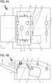
- FIG. 4A is a plan view of the post-processing apparatus 100.
- FIG. 4B is a side view of the post-processing apparatus 100 in a direction Y.
- the chain line indicates a reference position (reference line) as the widthwise center of the sheet conveyed in and ejected from the main device 100a.
- the broken line indicates a sheet conveyance passage along which the sheet is conveyed.
- the post-processing apparatus 100 includes entrance rollers 11, conveyance rollers 12, shift rollers 13, and output rollers 16.
- the entrance rollers 11 are disposed near an entrance into which the sheet ejected from the image forming apparatus 300 is conveyed.
- the entrance rollers 11 are located most upstream on the sheet conveyance passage in a sheet conveyance direction in which the sheet is conveyed.
- the conveyance rollers 12 are located downstream from the entrance rollers 11.
- the shift rollers 13 shift the sheet in the post-processing apparatus 100 in a direction (width direction) orthogonal to the sheet conveyance direction.
- the output rollers 16 are disposed near an output tray 20 onto which the sheet is ejected.
- the output rollers 16 are located most downstream on the sheet conveyance passage in the sheet conveyance direction.
- the output rollers 16 include pairs of an output driving roller 16a and an output driven roller 16b.
- the post-processing apparatus 100 further includes a reference fence 18 and an end fence 21.
- the leading end of the sheet in the sheet conveyance direction abuts against the reference fence 18 when the binding is executed.
- the trailing end of the ejected sheet in a sheet ejection direction in which the sheet is ejected abuts against the end fence 21.
- the sheets stopped by the reference fence 18 and the end fence 21 are aligned at the edges of the sheets in the sheet conveyance direction.
- the post-processing apparatus 100 further includes return rollers 14 and a tapping roller 15.
- the return rollers 14 convey the sheet toward the reference fence 18 and bring the sheet into contact with the reference fence 18.
- the tapping roller 15 conveys the sheet toward the reference fence 18.
- the post-processing apparatus 100 further includes a pair of jogger fences 22 (jogger fences 22a and 22b) to align the widthwise edges of a sheet P.
- the pair of jogger fences 22 can be displaced according to the size of the sheet.
- the jogger fences 22a and 22b sandwich the sheet P in directions indicated by arrows F in FIG. 4A to align the widthwise edges of the sheet P.
- the post-processing apparatus 100 further includes a binding device 19 (stapler) that performs binding and a staple tray 17 on which the sheets are stacked until the sheets are bound.
- a binding device 19 stapler
- the post-processing apparatus 100 has a "staple mode" and a "shift ejection mode.”
- staple mode the sheets ejected from the image forming apparatus 300 are bound.
- shift ejection mode the sheets ejected from the image forming apparatus 300 are conveyed and ejected without being subjected to post-processing. The user can select and set one of the modes as appropriate.
- the post-processing apparatus 100 receives and conveys a sheet ejected from the image forming apparatus 300 into the main device 100a with the entrance rollers 11. After conveying the sheet to the output rollers 16, the post-processing apparatus 100 ejects the sheet onto the output tray 20.
- the post-processing apparatus 100 receives and conveys the sheet ejected from the image forming apparatus 300 into the main device 100a with the entrance roller 11. After conveying the sheet to the shift rollers 13, the post-processing apparatus 100 ejects the sheet onto the staple tray 17. The post-processing apparatus 100 then causes the tapping roller 15 and the return rollers 14 to switch back the sheet to convey the sheet until the sheet end abuts against the reference fence 18. After conveying a plurality of sheets in the aforementioned way, the post-processing apparatus 100 binds the sheets as a sheet bundle with the binding device 19 and ejects the bound sheet bundle onto the output tray 20 by the rotation of the output rollers 16.
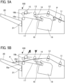
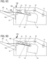
- FIGS. 5A to 5F a description is given below of a process in the staple mode according to the present embodiment.
- FIGS. 5A to 5F is a side view of the main device 100a of the post-processing apparatus 100 according to the present embodiment.
- FIGS. 5A to 5F illustrate a post-processing process of a sheet that is conveyed along the sheet conveyance passage after being ejected from the image forming apparatus 300.
- the broken line indicates the sheet conveyance passage along which the sheet P is conveyed.
- Each of arrows D1 and D2 indicates the sheet conveyance direction in which the sheet P is conveyed.
- the sheet P ejected from the image forming apparatus 300 is received and conveyed into the post-processing apparatus 100 by the entrance rollers 11.
- the sheet P is conveyed toward the staple tray 17 while the sheet P is not shifted and the output driven roller 16b is kept at a pressure release position.
- the sheet P is ejected onto the staple tray 17 by the shift rollers 13
- the sheet P is tapped and switched back toward the reference fence 18 by the tapping roller 15.
- the sheet P is conveyed by the tapping roller 15 and the return rollers 14 until the end of the sheet P abuts against the reference fence 18.
- the widthwise edges of the sheet P that has abutted against the reference fence 18 are aligned by the pair of jogger fences 22 (jogger fences 22a and 22b) illustrated in FIG. 4A .
- the first sheet P waits, in the state illustrated in FIG. 5D , for the subsequent sheet P to be conveyed as described above with reference to FIGS. 5A to 5D .
- the sheets P are sequentially stacked on the staple tray 17 as an aligned sheet bundle PS.
- the binding device 19 binds the sheet bundle PS.
- the output driven roller 16b moves to a nip position.
- the bound sheet bundle PS is ejected onto the output tray 20 by the output rollers 16 as illustrated in FIG. 5F .
- the post-processing apparatus 100 may include a plurality of binding means as a plurality of processing means.
- FIG. 6 is a plan view of the post-processing apparatus 100 (main device 100a) according to the present embodiment.
- the post-processing apparatus 100 illustrated in FIG. 6 includes, as the binding means, a staple-containing binding device 19 (stapler with staples) that performs binding with staples and a staple-free binding device 26 (stapler without staples) that performs binding without staples.
- the staple-free binding device 26 that performs binding without staples is disposed opposite the position at which the staple-containing binding device 19 is arranged, across the reference line in the direction Y.
- the relative positions of the staple-containing binding device 19 and the staple-free binding device 26 are not limited to those illustrated in FIG. 6 .
- the staple-free binding device 26 may be disposed at the position of the staple-containing binding device 19 illustrated in FIG. 6
- the staple-containing binding device 19 may be disposed at the position of the staple-free binding device 26 illustrated in FIG. 6 .
- either the staple-containing binding device 19 or the staple-free binding device 26 performs binding in the staple mode as described above with reference to FIGS. 5A to 5F .
- FIGS. 7A and 7B illustrates the post-processing apparatus 100 (main device 100a) according to the present embodiment.
- the post-processing apparatus 100 illustrated in FIGS. 7A and 7B includes the staple-free binding device 26.
- FIG. 7A is a plan view of the post-processing apparatus 100.
- FIG. 7B is a side view of the post-processing apparatus 100 in the direction Y.
- the staple-free binding device 26 performs binding in the staple mode as described above with reference to FIGS. 5A to 5F .
- FIGS. 8A, 8B , and 9 is a diagram illustrating the post-processing apparatus 100 as a medium processing apparatus according to an embodiment of the present disclosure.
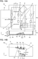
- FIG. 8A is a plan view of the post-processing apparatus 100.
- FIG. 8B is a side view of the post-processing apparatus 100.
- FIG. 9 is an external view of the post-processing apparatus 100.
- the post-processing apparatus 100 as the medium processing apparatus according to the present embodiment is an apparatus that performs binding as post-processing.
- the post-processing apparatus 100 includes binding means (binding devices) as post-processing means.
- the post-processing apparatus 100 includes the main device 100a, which performs post-processing on a sheet ejected from the image forming apparatus 300, and a manual processing device 100b.
- the chain line indicates a reference position (reference line) as the widthwise center of the sheet conveyed in and ejected from the main device 100a.
- the medium processing apparatus (the post-processing apparatus 100) is a medium processing apparatus installed in the image forming apparatus 300.
- the medium processing apparatus (the post-processing apparatus 100) according to the present embodiment includes a conveyor (conveying means), a slit 23, the medium processing devices 19 and 26 (medium processing means), a plurality of detectors 50 (detecting means) that includes detectors 50a, 50b, and 50c, and stoppers 25a and 25b.
- the conveyor conveys a medium ejected from the image forming apparatus 300.
- the slit 23 communicates with an opening of a housing 25 into which a medium is manually inserted from the outside.
- the slit 23 includes a placement face 23a on which the inserted medium is placed.
- the medium processing devices 19 and 26 process the medium conveyed by the conveyor and the medium placed on the slit 23.
- the detectors 50 (detectors 50a, 50b, and 50c) detect the medium.
- the placement face 23a is defined by a first side and a second side orthogonal to the first side.
- the first side and the second side of the placement face 23a are not parallel to directions Db and Dc in which the side faces of the housing 25 extend.
- the stoppers 25a and 25b regulate the edges of the medium along the first side and the second side of the placement face 23a.
- the detectors 50 are disposed on the stoppers 25a and 25b.
- the medium processing apparatus (the post-processing apparatus 100) is a medium processing apparatus installed in the image forming apparatus 300.
- the medium processing apparatus (the post-processing apparatus 100) according to the present embodiment includes a conveyor (conveying means), the slit 23, the medium processing devices 19 and 26 (medium processing means), the detectors 50 (detecting means) that includes the detectors 50a, 50b, and 50c, and the stoppers 25a and 25b.
- the conveyor conveys a medium ejected from the image forming apparatus 300.
- the slit 23 communicates with the opening of the housing 25 into which a medium is manually inserted from the outside.
- the slit 23 includes the placement face 23a on which the inserted medium is placed.
- the medium processing devices 19 and 26 process the medium conveyed by the conveyor and the medium placed on the slit 23.
- the detectors 50 (detectors 50a, 50b, and 50c) detect the medium.
- the placement face 23a is defined by a first side and a second side orthogonal to the first side. The first side and the second side of the placement face 23a are not parallel to a direction Da in which the conveyor conveys the medium.
- the stoppers 25a and 25b regulate the edges of the medium along the first side and the second side of the placement face 23a.
- the detectors 50 are disposed on the stoppers 25a and 25b.
- the post-processing apparatus 100 as the medium processing apparatus illustrated in FIGS. 8A and 8B includes, as the medium processing means, the staple-containing binding device 19 and the staple-free binding device 26 that bind media.
- the medium processing means provided with a rotation mechanism can be rotated in a direction R as illustrated in FIG. 8A to change the orientation of the medium processing means.
- the manual processing device 100b includes the first stopper 25a and the second stopper 25b.
- the first stopper 25a regulates a first edge of a rectangular medium, such as a sheet of paper, manually inserted into the slit 23.
- the second stopper 25b regulates a second edge orthogonal to the first edge of the rectangular medium.
- the first edge of the rectangular medium contacts a stopper (for example, the first stopper 25a) that is disposed along the first side of the placement face 23a, whereas the second edge of the rectangular medium orthogonal to the first edge contacts a stopper (for example, the second stopper 25b) that is disposed along the second side of the placement face 23a.
- a stopper for example, the first stopper 25a
- the second edge of the rectangular medium orthogonal to the first edge contacts a stopper (for example, the second stopper 25b) that is disposed along the second side of the placement face 23a.
- the rectangular medium such as a sheet of paper
- the first edge of the rectangular medium is stopped by the first stopper 25a whereas the second edge of the rectangular medium is stopped by the second stopper 25b.
- the recording medium is positioned.
- Each of the stoppers 25a and 25b includes a contact face that contacts the medium.
- the contact face is a face against which the medium abuts when the medium is set on the placement face 23a.
- the detectors 50 are disposed on the contact faces of the stoppers 25a and 25b.
- the detectors 50 may be sensors (for example, photosensors) that can detect contact with the medium.
- the medium processing apparatus preferably includes a placement detector (placement detecting means) to detect that a medium is placed on the placement face 23a.
- the sensors are preferably insensitive to contact with, for example, foreign matter other than the medium or a finger of a user.
- the medium processing apparatus preferably performs control such that the medium can be processed only when the placement of the medium is detected.
- the medium processing apparatus is allowed to bind media such as sheets of paper only when the placement of the media on the placement face 23a is detected, to enhance the safety of the user.
- the slit 23 is inclined at a predetermined angle with respect to the horizontal direction so that the medium is placed on substantially the same plane as the output tray 20.
- the aspect of the slit 23 is not limited to that illustrated in FIG. 8B .
- the slit 23 may be provided horizontally.
- the relative positions of the output tray 20 and the slit 23 are not particularly limited provided that the relative positions allow the binding means to perform both the processing in the main device 100a and the processing in the manual processing device 100b.
- a manual process is started when the user presses a start key 24 illustrated in FIGS. 8B and 9 .
- the home position (HP) of the processing means may be set to a position at which the manual process is performed.
- the manual process can be performed immediately in response to the start key 24 being pressed after the power of the medium processing apparatus is turned on.
- the placement face 23a of the manual processing device 100b of the medium processing apparatus is narrower than a placement face shaped such that either the first side or the second side is parallel to the direction Da in which the conveying means conveys media, or a placement face shaped parallel to the directions Db and Dc in which the side faces of the housing 25 extend.
- the placement faced 23a has a smaller area that supports the media placed thereon than the aforementioned placement faces. For this reason, for example, when the sheet bundle is set to be bound, the sheet bundle is likely to be inclined and may be failed to be bound.
- the medium processing apparatus includes a plurality of detecting means to detect whether the inserted medium is appropriately set and perform processing at a correct position.
- FIGS. 10A to 13B is a plan view of the manual processing device 100b, with sheets (or sheet bundle) P as media placed.
- FIGS. 10A to and 10B illustrates a comparative example in which the detector 50a is disposed only at one location on the stopper 25b.
- the set position of the sheets P may be inappropriate as illustrated in FIG. 10A .
- the medium may contact only the stopper 25b disposed along the side of the placement face 23a provided with the detector 50a, without contacting the stopper 25a disposed along the other side of the placement face 23a.
- the processing is executed even when the sheets P are placed as illustrated in FIGS. 10A or 10B .
- staples may remain in the apparatus and cause a failure.
- idle driving may reduce the strength of the teeth.
- FIGS. 11A, 11B , and 12A illustrates an example in which the two detectors (detectors 50a and 50b) are disposed only on the stopper 25b.
- FIG. 12B illustrates an example in which one of the two detectors (detector 50a) is disposed on the stopper 25b and the other detector (detector 50c) is disposed on the stopper 25a.
- the sheets P placed in an inclined state are detected by only one detector (detector 50a) and are not detected by the other detector (detector 50b).
- the medium processing apparatus detects that the sheets P are not appropriately set. In this case, the user may be notified of a warning.
- the medium processing apparatus detects that the sheets P are appropriately set.
- the medium process apparatus may erroneously detect that the sheets P are appropriately set.
- the detectors 50a and 50b detect the medium that is incorrectly placed as illustrated in FIG. 12A
- the medium processing apparatus may erroneously detect that the sheets P are appropriately set.
- the medium processing apparatus may erroneously detect that the sheets P are appropriately set.
- an increased number of detectors may be disposed at an increased number of locations.
- FIGS. 13A and 13B illustrates an example in which two of the three detectors (detectors 50a and 50b) are disposed on the stopper 25b whereas one of the three detectors (detector 50c) is disposed on the stopper 25a.
- the sheets P placed at the correct position are detected by the detectors 50a, 50b, and 50c.
- the medium processing apparatus detects that the sheets P are appropriately set. Regardless of the orientation of the sheets P, the medium processing apparatus can detect the sheets P.
- the detectors 50 are disposed at: at least two locations on the stopper 25b that is disposed along a longer one of the first side and the second side, and at least one location on the stopper 25a that is disposed along a shorter one of the first side and the second side.
- detectors are disposed is not limited to the above example.
- three or more detectors 50 may be disposed at three or more locations.
- FIGS. 14A and 14B are diagram illustrating the post-processing apparatus 100 as a medium processing apparatus according to an embodiment of the present disclosure.
- FIG. 14A is a plan view of the post-processing apparatus 100.
- FIG. 14B is a side view of the manual processing device 100b.
- the post-processing apparatus 100 as the medium processing apparatus according to the present embodiment is an apparatus that performs binding as post-processing.
- the post-processing apparatus 100 includes binding means (binding devices) as post-processing means.
- the post-processing apparatus 100 includes the main device 100a, which performs post-processing on a sheet ejected from the image forming apparatus 300, and a manual processing device 100b.
- the chain line indicates a reference position (reference line) as the widthwise center of the sheet conveyed in and ejected from the main device 100a.
- the medium processing apparatus includes a rotating unit (rotating means) and a control unit (control means).
- the rotating unit rotates the medium processing means in the horizontal direction.
- the control unit controls the amount of rotation of the rotating unit.
- the binding device as the medium processing means is provided with the rotating means.
- the rotating means includes a rotator 31 such as a drive motor and a movable part 30 that is connected to the rotator 31 and the staple-containing binding device 19.
- a rotator 31 such as a drive motor
- a movable part 30 that is connected to the rotator 31 and the staple-containing binding device 19.
- the staple-free binding device 26 has a configuration like the configuration described above.
- the control means controls the direction and amount of rotation of the rotating means.
- Such control enables desired processing such as oblique binding or horizontal binding.
- the medium processing apparatus binds the media obliquely with respect to the edge of the media.
- the medium processing apparatus binds the media horizontally with respect to the edge of the media.
- the medium processing apparatus includes a movable member 33 that enables the medium processing means to reciprocate in directions indicated by double-headed arrow M in FIG. 14A .
- the staple-containing binding device 19 is attached to the movable member 33 through a fixed part 32 as illustrated in FIG. 14B .
- the staple-free binding device 26 has a configuration like the configuration described above.
- the control means controls the direction and amount of movement of the movable member 33.
- the processing means can be moved to and disposed at a desired processing position.
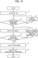
- FIG. 15 is a flowchart of a manual process in the medium processing apparatus according to the present embodiment.
- the manual process starts when a user presses the start key 24.
- step S1 the start key 24 is turned on.
- step S2 the control unit 306 determines whether the main device 100a is in the processing operation (for example, in the staple mode). When the main device 100a is in the processing operation (YES in step S2), in step S3, the control unit 306 displays an instruction of job standby on the operation panel 310 to notify the user of the instruction.
- FIG. 16A illustrates an image displayed on the operation panel 310 at this time, according to the present embodiment.
- step S4 the detectors 50 detect the set media.
- the medium processing apparatus includes the multiple detectors 50 (detecting means).
- the CPU 102a determines whether the media are appropriately set, depending on whether all of the detectors 50 have detected the media as illustrated in, for example, FIGS. 13A and 13B .
- step S5 When any of the detectors 50 (for example, any one or two of three detectors disposed at three locations) has not detected the media (NO in step S5), the CPU 102a determines that the media are inappropriately set. In step S6, the control unit 306 displays, on the operation panel 310, a warning that the media are inappropriately set.
- FIG. 16B illustrates an image displayed on the operation panel 310 at this time, according to the present embodiment.
- the user who has confirmed the warning displayed can correct the setting of the media.
- step S4 the detectors 50 detect the media again. This flow is repeated until the media are appropriately set.
- step S5 When all of the detectors 50 have detected the media (YES in step S5), the CPU 102a determines that the media are appropriately set. In step S7, the CPU 102a executes processing. In step S8, the control unit 306 displays, on the operation panel 310, a message indicating that the processing is in progress.
- FIG. 16C illustrates an image displayed on the operation panel 310 at this time, according to the present embodiment.
- the configuration according to the embodiments of the present disclosure can also be applied to a medium processing apparatus that performs post-processing other than binding.
- a medium processing apparatus to be installed in an image forming apparatus includes conveying means, a slit, medium processing means, a plurality of detecting means, and a stopper.
- the conveying means conveys a medium ejected from the image forming apparatus.
- the slit communicates with an opening of a housing into which a medium is manually inserted from the outside.
- the slit includes a placement face on which the inserted medium is placed.
- the medium processing means processes the medium conveyed by the conveying means or the medium placed on the slit.
- the detecting means detect the medium.
- the placement face has a first side and a second side orthogonal to the first side. The first side and the second side are not parallel to a direction in which a side face of the housing extends.
- the stopper regulates edges of the medium along the first side and the second side of the placement face.
- the detecting means are disposed on the stopper.
- a medium processing apparatus to be installed in an image forming apparatus includes conveying means, a slit, medium processing means, a plurality of detecting means, and a stopper.
- the conveying means conveys a medium ejected from the image forming apparatus.
- the slit communicates with an opening of a housing into which a medium is manually inserted from the outside.
- the slit includes a placement face on which the inserted medium is placed.
- the medium processing means processes the medium conveyed by the conveying means or the medium placed on the slit.
- the detecting means detect the medium.
- the placement face has a first side and a second side orthogonal to the first side. The first side and the second side of the placement face are not parallel to a direction in which the conveying means conveys the medium.
- the stopper regulates edges of the medium along the first side and the second side of the placement face.
- the detecting means are disposed on the stopper.
- the medium processing apparatus of the first or second aspect further includes rotating means and control means.
- the rotating means rotates the medium processing means in a horizontal direction.
- the control means controls an amount of rotation of the rotating means.
- the medium is a rectangular medium and includes a first edge and a second edge orthogonal to the first edge.
- the first edge of the rectangular medium contacts the stopper disposed along the first side.
- the second edge of the rectangular medium contacts the stopper disposed along the second side.
- the detecting means include placement detecting means to detect that the medium is placed on the placement face.
- the placement face has a first side and a second side of different lengths.
- the detecting means are disposed at: at least two locations on the stopper disposed along a longer one of the first side and the second side, and at least one location on the stopper disposed along a shorter one of the first side and the second side.
- an image forming system includes an image forming apparatus that forms an image on a medium and the medium processing apparatus according to any one of the first to sixth aspects.
- the medium processing apparatus performs post-processing on the medium on which the image is formed by the image forming unit.
- the present invention can be implemented in any convenient form, for example using dedicated hardware, or a mixture of dedicated hardware and software.
- the present invention may be implemented as computer software implemented by one or more networked processing apparatuses.
- the processing apparatuses include any suitably programmed apparatuses such as a general purpose computer, a personal digital assistant, a Wireless Application Protocol (WAP) or third-generation (3G)-compliant mobile telephone, and so on. Since the present invention can be implemented as software, each and every aspect of the present invention thus encompasses computer software implementable on a programmable device.
- the computer software can be provided to the programmable device using any conventional carrier medium (carrier means).
- the carrier medium includes a transient carrier medium such as an electrical, optical, microwave, acoustic or radio frequency signal carrying the computer code.
- transient medium is a Transmission Control Protocol/Internet Protocol (TCP/IP) signal carrying computer code over an IP network, such as the Internet.
- the carrier medium may also include a storage medium for storing processor readable code such as a floppy disk, a hard disk, a compact disc read-only memory (CD-ROM), a magnetic tape device, or a solid state memory device.
Landscapes
- Engineering & Computer Science (AREA)
- Textile Engineering (AREA)
- Physics & Mathematics (AREA)
- General Physics & Mathematics (AREA)
- Mechanical Engineering (AREA)
- Folding Of Thin Sheet-Like Materials, Special Discharging Devices, And Others (AREA)
- Accessory Devices And Overall Control Thereof (AREA)
- Pile Receivers (AREA)
Abstract
A medium processing apparatus (100) for processing a medium ejected from an image forming apparatus includes conveying means (11, 12, 13), a slit (23), medium processing means (19, 26), a stopper (25a, 25b), and a plurality of detecting means (50). The conveying means (11, 12, 13) conveys the medium ejected from the image forming apparatus. The slit (23) communicates with an opening of a housing (25) into which a medium is manually inserted from outside. The slit (23) includes a placement face (23a) on which the inserted medium is placed. The placement face (23a) has a first side and a second side orthogonal to the first side. The first side and the second side are not parallel to a direction in which a side face of the housing (25) extends. The medium processing means (19, 26) processes the medium conveyed by the conveying means (11, 12, 13) or the medium placed on the slit (23). The stopper (25a, 25b) regulates edges of the medium along the first side and the second side of the placement face (23a). The plurality of detecting means (50) is disposed on the stopper (25a, 25b) to detect the medium.
Description
- Embodiments of the present disclosure relate to a medium processing apparatus and an image forming system incorporating the medium processing apparatus.
- Medium processing apparatuses have been developed as post-processing apparatuses to perform post-processing such as binding sheets on which images are formed by image forming apparatuses.
- Some medium processing apparatuses have a manual processing structure that enables processing by manual operation (manual processing) on a medium such as a sheet of paper manually inserted by a user.
- When a medium is processed, the medium is to be placed at an appropriate position. An apparatus has been proposed that includes a positioning structure to perform processing on a desired point on a medium (for example, see
Japanese Unexamined Patent Application Publication No. 2019-181733 -
Japanese Unexamined Patent Application Publication No. 2019-181733 - The apparatus disclosed in
Japanese Unexamined Patent Application Publication No. 2019-181733 - However, when the medium is inserted obliquely in an inclined position relative to an appropriate set position, the apparatus may fail to bind a desired point on the medium.
- According to an embodiment of the present invention, a medium processing apparatus for processing a medium ejected from an image forming apparatus includes conveying means, a slit, medium processing means, a stopper, and a plurality of detecting means. The conveying means conveys the medium ejected from the image forming apparatus. The slit communicates with an opening of a housing into which a medium is manually inserted from outside. The slit includes a placement face on which the inserted medium is placed. The placement face has a first side and a second side orthogonal to the first side. The first side and the second side are not parallel to a direction in which a side face of the housing extends. The medium processing means processes the medium conveyed by the conveying means or the medium placed on the slit. The stopper regulates edges of the medium along the first side and the second side of the placement face. The plurality of detecting means is disposed on the stopper to detect the medium.
- According to an embodiment of the present invention, a medium processing apparatus for processing a medium ejected from an image forming apparatus includes conveying means, a slit, medium processing means, a stopper, and a plurality of detecting means. The conveying means conveys the medium ejected from the image forming apparatus. The slit communicates with an opening of a housing into which a medium is manually inserted from outside. The slit includes a placement face on which the inserted medium is placed. The placement face has a first side and a second side orthogonal to the first side. The first side and the second side are not parallel to a direction in which the conveying means conveys the medium. The medium processing means processes the medium conveyed by the conveying means or the medium placed on the slit. The stopper regulates edges of the medium along the first side and the second side of the placement face. The plurality of detecting means is disposed on the stopper to detect the medium.
- According to an embodiment of the present invention, an image forming system includes an image forming apparatus that forms an image on a medium and the medium processing apparatus that performs post-processing on the medium on which the image is formed by the image forming apparatus.
- Accordingly, the medium processing apparatus detects whether an inserted medium is appropriately set and performs processing at the correct position.
- A more complete appreciation of embodiments of the present disclosure and many of the attendant advantages and features thereof can be readily obtained and understood from the following detailed description with reference to the accompanying drawings, wherein:
-
FIGS. 1A and 1B are schematic diagrams each illustrating a configuration of an image forming system according to an embodiment of the present disclosure; -
FIG. 2A is a block diagram illustrating the image forming system ofFIG. 1A ; -
FIG. 2B is a block diagram illustrating the image forming system ofFIG. 1B ; -
FIG. 3 is a block diagram illustrating a hardware configuration of an image forming system according to an embodiment of the present disclosure; -
FIG. 4A is a plan view of a medium processing apparatus according to an embodiment of the present disclosure; -
FIG. 4B is a side view of the medium processing apparatus ofFIG. 4A ; -
FIGS. 5A to 5F are diagrams illustrating a process performed on a medium ejected from an image forming apparatus, according to an embodiment of the present disclosure. -
FIG. 6 is a plan view of a medium processing apparatus according to an embodiment of the present disclosure; -
FIG. 7A is a plan view of a medium processing apparatus according to an embodiment of the present disclosure; -
FIG. 7B is a side view of the medium processing apparatus ofFIG. 7A ; -
FIG. 8A is a plan view of a medium processing apparatus according to an embodiment of the present disclosure; -
FIG. 8B is a side view of the medium processing apparatus ofFIG. 8A ; -
FIG. 9 is an external perspective view of a medium processing device according to an embodiment of the present disclosure; -
FIG. 10A is a diagram illustrating a first example of the detection of a medium set on a placement face with a detector; -
FIG. 10B is a diagram illustrating a second example of the detection of a medium set on the placement face with the detector; -
FIG. 11A is a diagram illustrating a first example of the detection of a medium set on a placement face with one of two detectors; -
FIG. 11B is a diagram illustrating a second example of the detection of a medium set on a placement face with the two detectors; -
FIG. 12A is a diagram illustrating a first example of the detection of a medium set on a placement face with two detectors; -
FIG. 12B is a diagram illustrating a second example of the detection of a medium set on a placement face with two detectors; -
FIG. 13A is a diagram illustrating a first example of the detection of a medium set on a placement face with three detectors; -
FIG. 13B is a diagram illustrating a second example of the detection of a medium set on the placement face with the three detectors; -
FIG. 14A is a plan view of a medium processing apparatus according to an embodiment of the present disclosure; -
FIG. 14B is a side view of the medium processing apparatus ofFIG. 14A ; -
FIG. 15 is a flowchart of a manual process according to an embodiment of the present disclosure; and -
FIGS. 16A to 16C are diagrams each illustrating a display example on a control panel according to an embodiment of the present disclosure. - The accompanying drawings are intended to depict embodiments of the present disclosure and should not be interpreted to limit the scope thereof. The accompanying drawings are not to be considered as drawn to scale unless explicitly noted. Also, identical or similar reference numerals designate identical or similar components throughout the several views.
- In describing embodiments illustrated in the drawings, specific terminology is employed for the sake of clarity. However, the disclosure of this specification is not intended to be limited to the specific terminology so selected and it is to be understood that each specific element includes all technical equivalents that have a similar function, operate in a similar manner, and achieve a similar result.
- Referring to the drawings, embodiments of the present disclosure are described below.
- As used herein, the singular forms "a," "an," and "the" are intended to include the plural forms as well, unless the context clearly indicates otherwise.
- For the sake of simplicity, like reference signs denote like elements such as parts and materials having the same functions, and redundant descriptions thereof are omitted unless otherwise required.
- As used herein, the term "connected/coupled" includes both direct connections and connections in which there are one or more intermediate connecting elements.
- Each of
FIGS. 1A and 1B is an external schematic view of animage forming system 1000, which includes apost-processing apparatus 100 as a medium processing apparatus and animage forming apparatus 300 according to the present embodiment. - The
image forming apparatus 300 is, for example, an apparatus that forms an image on a medium by an electrophotographic process. - In the following description, a medium to be processed by the
image forming apparatus 300, thepost-processing apparatus 100, and anoptional apparatus 200 is described as a sheet. However, the medium is not limited to a paper medium. Alternatively, for example, the medium may be a plastic sheet, a cloth sheet, or a metal sheet. -
FIG. 1A illustrates a configuration of theimage forming apparatus 300 equipped with the post-processing apparatus 100 (inner finisher) as the medium processing apparatus, according to the present embodiment. After a sheet is subjected to image forming processing in theimage forming apparatus 300 and ejected from theimage forming apparatus 300, the sheet is conveyed to thepost-processing apparatus 100 and subjected to post-processing such as binding. -
FIG. 1B illustrates a configuration of theimage forming apparatus 300 equipped with thepost-processing apparatus 100 and theoptional apparatus 200, according to the present embodiment. After a sheet is subjected to the image forming processing in theimage forming apparatus 300 and ejected from theimage forming apparatus 300, the sheet is conveyed to theoptional apparatus 200 and subjected to post-processing such as punching or folding. The post-processed medium is then conveyed to thepost-processing apparatus 100 and subjected to post-processing such as binding. A user can appropriately determine whether to install theoptional apparatus 200 in theimage forming apparatus 300. - Each of
FIGS. 2A and 2B is a block diagram of theimage forming system 1000, which includes theimage forming apparatus 300 and thepost-processing apparatus 100 illustrated inFIGS. 1A and 1B , according to the present embodiment. Theimage forming system 1000 illustrated inFIG. 2A includes theoptional apparatus 200 illustrated inFIG. 1B , in addition to theimage forming apparatus 300 and thepost-processing apparatus 100. In each ofFIGS. 2A and 2B , the flow of communication signals is indicated by solid lines, whereas the flow of sheets is indicated by broken lines. -
FIG. 2A is a block diagram illustrating theimage forming system 1000 ofFIG. 1A . - The
image forming apparatus 300 includes adisplay unit 301, anoperation unit 302, anoperation panel 310, asheet feeding unit 303, animage forming unit 304, a fixingunit 305, and acontrol unit 306. Thedisplay unit 301 notifies the user of the state of various devices and the operation contents of the apparatus. Theoperation unit 302 allows the user to set, for example, an operation mode and the number of copies. Thesheet feeding unit 303 stocks sheets and feeds the sheets one by one. Theimage forming unit 304 forms a latent image on a photoconductor and transfers the image onto a sheet. The fixingunit 305 fixes the image transferred onto the sheet. Thecontrol unit 306 controls these units. - The
post-processing apparatus 100 includes acontrol unit 102 and aprocessing unit 101. - The
control unit 306 of theimage forming apparatus 300 instructs, through acommunication line 307, thecontrol unit 102 to cause theprocessing unit 101 to perform the designated processing on the designated sheet. Examples of information exchanged through thecommunication line 307 include, but are not limited to, information on the type and mode of processing to be performed on a sheet, information on the size of a sheet, and information on the processing timing. Such a configuration enables the system to operate. -
FIG. 2B is a block diagram illustrating theimage forming system 1000 ofFIG. 1B . - The configurations of the
image forming apparatus 300 and thepost-processing apparatus 100 are the same as those illustrated inFIG. 2A . - The
optional apparatus 200 includes acontrol unit 202 and aprocessing unit 201. - The
control unit 102 of thepost-processing apparatus 100 instructs, through acommunication line 103, thecontrol unit 202 to cause theprocessing unit 201 to perform the designated processing on the designated sheet. Like the information exchanged through thecommunication line 307, examples of information exchanged through thecommunication line 103 include, but are not limited to, information on the type and mode of processing to be performed on a sheet, information on the size of a sheet, and information on the processing timing. Such a configuration enables the system to operate. -
FIG. 3 is a block diagram illustrating a hardware configuration of theimage forming system 1000 according to the present embodiment. - The
control unit 102 of thepost-processing apparatus 100 is connected to thecontrol unit 306 of theimage forming apparatus 300 through an interface (I/F) 102b. Thepost-processing apparatus 100 is controlled according to processing signals from theimage forming apparatus 300. - A central processing unit (CPU) 102a is processing means to control the entire operation of the
post-processing apparatus 100. - The
image forming system 1000 illustrated inFIG. 3 includes, as optional apparatuses, theoptional apparatus 200 that performs punching and anoptional apparatus 400 that performs folding. - The
control unit 202 of theoptional apparatus 200 is connected to theCPU 102a of thepost-processing apparatus 100 through an I/F 202a. Acontrol unit 402 of theoptional apparatus 400 is connected to theCPU 102a of thepost-processing apparatus 100 through an I/F 402a. Thecontrol unit 102 of thepost-processing apparatus 100 controls the operations of thecontrol unit 202 of theoptional apparatus 200 and thecontrol unit 402 of theoptional apparatus 400. - The
post-processing apparatus 100, theoptional apparatus 200, and theoptional apparatus 400 are detachable apparatuses. Similarly, the I/F 102b, the I/F 202a, and the I/F 402a are detachable in hardware by, for example, relay connectors or drawer connectors. - The
control unit 102 of thepost-processing apparatus 100 is connected to aconveyance motor 111, asheet ejection motor 112, astaple driving motor 113, aconveyance sensor 114, asheet ejection sensor 115, and a staple movement home position (HP)sensor 116 through an I/F 102c. - A punching
motor 211, thepunch movement motor 212, thepre-punching sensor 213, the cover opening/closing sensor 214, and the punchingunit HP sensor 215 of thecontrol unit 202 of theoptional apparatus 200 are connected to theCPU 102a through the I/F 202a. - A
folding motor 411, anentrance sensor 412, and afolding sensor 413 of thecontrol unit 402 of theoptional apparatus 400 are connected to theCPU 102a through the I/F 402a. - Each of
FIGS. 4A, 4B , and5A to 5F is a diagram illustrating the configuration and operation of amain device 100a, which is a body of thepost-processing apparatus 100 serving as a medium processing apparatus according to an embodiment of the present disclosure. Themain device 100a executes post-processing on a sheet ejected from theimage forming apparatus 300. - The
post-processing apparatus 100 according to the present embodiment is an apparatus that performs binding as post-processing. Thepost-processing apparatus 100 includes binding means (a binding device) as post-processing means. - Specifically,
FIG. 4A is a plan view of thepost-processing apparatus 100.FIG. 4B is a side view of thepost-processing apparatus 100 in a direction Y. - In
FIG. 4A , the chain line indicates a reference position (reference line) as the widthwise center of the sheet conveyed in and ejected from themain device 100a. - In
FIG. 4B , the broken line indicates a sheet conveyance passage along which the sheet is conveyed. - As illustrated in
FIGS. 4A and 4B , thepost-processing apparatus 100 includesentrance rollers 11,conveyance rollers 12,shift rollers 13, andoutput rollers 16. Theentrance rollers 11 are disposed near an entrance into which the sheet ejected from theimage forming apparatus 300 is conveyed. Theentrance rollers 11 are located most upstream on the sheet conveyance passage in a sheet conveyance direction in which the sheet is conveyed. Theconveyance rollers 12 are located downstream from theentrance rollers 11. Theshift rollers 13 shift the sheet in thepost-processing apparatus 100 in a direction (width direction) orthogonal to the sheet conveyance direction. Theoutput rollers 16 are disposed near anoutput tray 20 onto which the sheet is ejected. Theoutput rollers 16 are located most downstream on the sheet conveyance passage in the sheet conveyance direction. Theoutput rollers 16 include pairs of anoutput driving roller 16a and an output drivenroller 16b. - The
post-processing apparatus 100 further includes areference fence 18 and anend fence 21. The leading end of the sheet in the sheet conveyance direction abuts against thereference fence 18 when the binding is executed. The trailing end of the ejected sheet in a sheet ejection direction in which the sheet is ejected abuts against theend fence 21. The sheets stopped by thereference fence 18 and theend fence 21 are aligned at the edges of the sheets in the sheet conveyance direction. - The
post-processing apparatus 100 further includesreturn rollers 14 and a tappingroller 15. Thereturn rollers 14 convey the sheet toward thereference fence 18 and bring the sheet into contact with thereference fence 18. The tappingroller 15 conveys the sheet toward thereference fence 18. - As illustrated in
FIG. 4A , thepost-processing apparatus 100 further includes a pair of jogger fences 22 (jogger fences jogger fences FIG. 4A to align the widthwise edges of the sheet P. - The
post-processing apparatus 100 further includes a binding device 19 (stapler) that performs binding and astaple tray 17 on which the sheets are stacked until the sheets are bound. - The
post-processing apparatus 100 according to the present embodiment has a "staple mode" and a "shift ejection mode." In the staple mode, the sheets ejected from theimage forming apparatus 300 are bound. In the shift ejection mode, the sheets ejected from theimage forming apparatus 300 are conveyed and ejected without being subjected to post-processing. The user can select and set one of the modes as appropriate. - In the shift ejection mode, the
post-processing apparatus 100 receives and conveys a sheet ejected from theimage forming apparatus 300 into themain device 100a with theentrance rollers 11. After conveying the sheet to theoutput rollers 16, thepost-processing apparatus 100 ejects the sheet onto theoutput tray 20. - In the staple mode, the
post-processing apparatus 100 receives and conveys the sheet ejected from theimage forming apparatus 300 into themain device 100a with theentrance roller 11. After conveying the sheet to theshift rollers 13, thepost-processing apparatus 100 ejects the sheet onto thestaple tray 17. Thepost-processing apparatus 100 then causes the tappingroller 15 and thereturn rollers 14 to switch back the sheet to convey the sheet until the sheet end abuts against thereference fence 18. After conveying a plurality of sheets in the aforementioned way, thepost-processing apparatus 100 binds the sheets as a sheet bundle with thebinding device 19 and ejects the bound sheet bundle onto theoutput tray 20 by the rotation of theoutput rollers 16. - Referring to
FIGS. 5A to 5F , a description is given below of a process in the staple mode according to the present embodiment. - Each of
FIGS. 5A to 5F is a side view of themain device 100a of thepost-processing apparatus 100 according to the present embodiment.FIGS. 5A to 5F illustrate a post-processing process of a sheet that is conveyed along the sheet conveyance passage after being ejected from theimage forming apparatus 300. In each ofFIGS. 5A to 5F , the broken line indicates the sheet conveyance passage along which the sheet P is conveyed. Each of arrows D1 and D2 indicates the sheet conveyance direction in which the sheet P is conveyed. - As illustrated in
FIG. 5A , the sheet P ejected from theimage forming apparatus 300 is received and conveyed into thepost-processing apparatus 100 by theentrance rollers 11. - As illustrated in
FIG. 5B , the sheet P is conveyed toward thestaple tray 17 while the sheet P is not shifted and the output drivenroller 16b is kept at a pressure release position. - As illustrated in
FIG. 5C , after the sheet P is ejected onto thestaple tray 17 by theshift rollers 13, the sheet P is tapped and switched back toward thereference fence 18 by the tappingroller 15. - As illustrated in
FIG. 5D , the sheet P is conveyed by the tappingroller 15 and thereturn rollers 14 until the end of the sheet P abuts against thereference fence 18. - The widthwise edges of the sheet P that has abutted against the
reference fence 18 are aligned by the pair of jogger fences 22 (jogger fences FIG. 4A . - The first sheet P waits, in the state illustrated in
FIG. 5D , for the subsequent sheet P to be conveyed as described above with reference toFIGS. 5A to 5D . - As illustrated in
FIG. 5E , the sheets P are sequentially stacked on thestaple tray 17 as an aligned sheet bundle PS. The bindingdevice 19 binds the sheet bundle PS. The bindingdevice 19, which is a stapler with staples, drives staples into predetermined points on the sheet bundle PS to bind the sheet bundle PS. The output drivenroller 16b moves to a nip position. - The bound sheet bundle PS is ejected onto the
output tray 20 by theoutput rollers 16 as illustrated inFIG. 5F . - The
post-processing apparatus 100 may include a plurality of binding means as a plurality of processing means. -
FIG. 6 is a plan view of the post-processing apparatus 100 (main device 100a) according to the present embodiment. Thepost-processing apparatus 100 illustrated inFIG. 6 includes, as the binding means, a staple-containing binding device 19 (stapler with staples) that performs binding with staples and a staple-free binding device 26 (stapler without staples) that performs binding without staples. - In the
post-processing apparatus 100 illustrated inFIG. 6 , the staple-freebinding device 26 that performs binding without staples is disposed opposite the position at which the staple-containingbinding device 19 is arranged, across the reference line in the direction Y. The relative positions of the staple-containingbinding device 19 and the staple-freebinding device 26 are not limited to those illustrated inFIG. 6 . Alternatively, for example, the staple-freebinding device 26 may be disposed at the position of the staple-containingbinding device 19 illustrated inFIG. 6 , whereas the staple-containingbinding device 19 may be disposed at the position of the staple-freebinding device 26 illustrated inFIG. 6 . - In the
post-processing apparatus 100 illustrated inFIG. 6 , either the staple-containingbinding device 19 or the staple-freebinding device 26 performs binding in the staple mode as described above with reference toFIGS. 5A to 5F . - Each of
FIGS. 7A and 7B illustrates the post-processing apparatus 100 (main device 100a) according to the present embodiment. Thepost-processing apparatus 100 illustrated inFIGS. 7A and 7B includes the staple-freebinding device 26. - Specifically,
FIG. 7A is a plan view of thepost-processing apparatus 100.FIG. 7B is a side view of thepost-processing apparatus 100 in the direction Y. - In the
post-processing apparatus 100 illustrated inFIGS. 7A and 7B , the staple-freebinding device 26 performs binding in the staple mode as described above with reference toFIGS. 5A to 5F . - Each of
FIGS. 8A, 8B , and9 is a diagram illustrating thepost-processing apparatus 100 as a medium processing apparatus according to an embodiment of the present disclosure. - Specifically,
FIG. 8A is a plan view of thepost-processing apparatus 100.FIG. 8B is a side view of thepost-processing apparatus 100.FIG. 9 is an external view of thepost-processing apparatus 100. - The
post-processing apparatus 100 as the medium processing apparatus according to the present embodiment is an apparatus that performs binding as post-processing. Thepost-processing apparatus 100 includes binding means (binding devices) as post-processing means. - The
post-processing apparatus 100 according to the present embodiment includes themain device 100a, which performs post-processing on a sheet ejected from theimage forming apparatus 300, and amanual processing device 100b. - In
FIG. 8A , the chain line indicates a reference position (reference line) as the widthwise center of the sheet conveyed in and ejected from themain device 100a. - The medium processing apparatus (the post-processing apparatus 100) according to the present embodiment is a medium processing apparatus installed in the
image forming apparatus 300. The medium processing apparatus (the post-processing apparatus 100) according to the present embodiment includes a conveyor (conveying means), aslit 23, themedium processing devices 19 and 26 (medium processing means), a plurality of detectors 50 (detecting means) that includesdetectors stoppers image forming apparatus 300. Theslit 23 communicates with an opening of ahousing 25 into which a medium is manually inserted from the outside. Theslit 23 includes aplacement face 23a on which the inserted medium is placed. Themedium processing devices slit 23. The detectors 50 (detectors placement face 23a is defined by a first side and a second side orthogonal to the first side. The first side and the second side of theplacement face 23a are not parallel to directions Db and Dc in which the side faces of thehousing 25 extend. Thestoppers placement face 23a. The detectors 50 are disposed on thestoppers - The medium processing apparatus (the post-processing apparatus 100) according to the present embodiment is a medium processing apparatus installed in the
image forming apparatus 300. The medium processing apparatus (the post-processing apparatus 100) according to the present embodiment includes a conveyor (conveying means), theslit 23, themedium processing devices 19 and 26 (medium processing means), the detectors 50 (detecting means) that includes thedetectors stoppers image forming apparatus 300. Theslit 23 communicates with the opening of thehousing 25 into which a medium is manually inserted from the outside. Theslit 23 includes theplacement face 23a on which the inserted medium is placed. Themedium processing devices slit 23. The detectors 50 (detectors placement face 23a is defined by a first side and a second side orthogonal to the first side. The first side and the second side of theplacement face 23a are not parallel to a direction Da in which the conveyor conveys the medium. Thestoppers placement face 23a. The detectors 50 are disposed on thestoppers - The
post-processing apparatus 100 as the medium processing apparatus illustrated inFIGS. 8A and 8B includes, as the medium processing means, the staple-containingbinding device 19 and the staple-freebinding device 26 that bind media. - The medium processing means provided with a rotation mechanism can be rotated in a direction R as illustrated in
FIG. 8A to change the orientation of the medium processing means. - As illustrated in
FIG. 8A , themanual processing device 100b includes thefirst stopper 25a and thesecond stopper 25b. Thefirst stopper 25a regulates a first edge of a rectangular medium, such as a sheet of paper, manually inserted into theslit 23. Thesecond stopper 25b regulates a second edge orthogonal to the first edge of the rectangular medium. - The first edge of the rectangular medium contacts a stopper (for example, the
first stopper 25a) that is disposed along the first side of theplacement face 23a, whereas the second edge of the rectangular medium orthogonal to the first edge contacts a stopper (for example, thesecond stopper 25b) that is disposed along the second side of theplacement face 23a. - When the rectangular medium such as a sheet of paper is manually inserted into the
slit 23 and placed on theplacement face 23a, the first edge of the rectangular medium is stopped by thefirst stopper 25a whereas the second edge of the rectangular medium is stopped by thesecond stopper 25b. Thus, the recording medium is positioned. - Each of the
stoppers placement face 23a. The detectors 50 are disposed on the contact faces of thestoppers - The detectors 50 may be sensors (for example, photosensors) that can detect contact with the medium.
- The medium processing apparatus according to the present embodiment preferably includes a placement detector (placement detecting means) to detect that a medium is placed on the
placement face 23a. The sensors are preferably insensitive to contact with, for example, foreign matter other than the medium or a finger of a user. The medium processing apparatus according to the present embodiment preferably performs control such that the medium can be processed only when the placement of the medium is detected. - For example, the medium processing apparatus is allowed to bind media such as sheets of paper only when the placement of the media on the
placement face 23a is detected, to enhance the safety of the user. - In the example illustrated in
FIG. 8B , theslit 23 is inclined at a predetermined angle with respect to the horizontal direction so that the medium is placed on substantially the same plane as theoutput tray 20. However, the aspect of theslit 23 is not limited to that illustrated inFIG. 8B . Alternatively, for example, theslit 23 may be provided horizontally. - The relative positions of the
output tray 20 and theslit 23 are not particularly limited provided that the relative positions allow the binding means to perform both the processing in themain device 100a and the processing in themanual processing device 100b. - A manual process is started when the user presses a start key 24 illustrated in
FIGS. 8B and9 . - The home position (HP) of the processing means may be set to a position at which the manual process is performed. In this case, the manual process can be performed immediately in response to the start key 24 being pressed after the power of the medium processing apparatus is turned on.
- The
placement face 23a of themanual processing device 100b of the medium processing apparatus according to the present embodiment is narrower than a placement face shaped such that either the first side or the second side is parallel to the direction Da in which the conveying means conveys media, or a placement face shaped parallel to the directions Db and Dc in which the side faces of thehousing 25 extend. In addition, the placement faced 23a has a smaller area that supports the media placed thereon than the aforementioned placement faces. For this reason, for example, when the sheet bundle is set to be bound, the sheet bundle is likely to be inclined and may be failed to be bound. - To prevent such a binding failure, the medium processing apparatus according to the present embodiment includes a plurality of detecting means to detect whether the inserted medium is appropriately set and perform processing at a correct position.
- Referring to
FIGS. 10A to 13B , a description is given below of some examples of detection with detecting means. - Each of
FIGS. 10A to 13B is a plan view of themanual processing device 100b, with sheets (or sheet bundle) P as media placed. - Specifically, each of
FIGS. 10A to and 10B illustrates a comparative example in which thedetector 50a is disposed only at one location on thestopper 25b. - When the
detector 50a detects the sheets P, the set position of the sheets P may be inappropriate as illustrated inFIG. 10A . As illustrated inFIG. 10B , the medium may contact only thestopper 25b disposed along the side of theplacement face 23a provided with thedetector 50a, without contacting thestopper 25a disposed along the other side of theplacement face 23a. - When the
single detector 50a is disposed alone, the processing is executed even when the sheets P are placed as illustrated inFIGS. 10A or 10B . In this case, in the processing with the staple-containingbinding device 19, staples may remain in the apparatus and cause a failure. In the processing with the staple-freebinding device 26, idle driving may reduce the strength of the teeth. - A description is given below of some examples in which two detectors (detecting means) are disposed.
- Each of
FIGS. 11A, 11B , and12A illustrates an example in which the two detectors (detectors stopper 25b.FIG. 12B illustrates an example in which one of the two detectors (detector 50a) is disposed on thestopper 25b and the other detector (detector 50c) is disposed on thestopper 25a. - As illustrated in
FIG. 11A , the sheets P placed in an inclined state are detected by only one detector (detector 50a) and are not detected by the other detector (detector 50b). Thus, the medium processing apparatus detects that the sheets P are not appropriately set. In this case, the user may be notified of a warning. - On the other hand, as illustrated in
FIG. 11B , the sheets P placed at the correct position are detected by thedetectors - However, even when the medium processing apparatus includes two detectors, the medium process apparatus may erroneously detect that the sheets P are appropriately set. For example, when the
detectors FIG. 12A , the medium processing apparatus may erroneously detect that the sheets P are appropriately set. - Alternatively, when the
detectors stoppers FIG. 12B , the medium processing apparatus may erroneously detect that the sheets P are appropriately set. - To prevent such erroneous detection, an increased number of detectors (detecting means) may be disposed at an increased number of locations.
- A description is given below of an example in which three detectors (detecting means) are disposed.
- Each of
FIGS. 13A and 13B illustrates an example in which two of the three detectors (detectors stopper 25b whereas one of the three detectors (detector 50c) is disposed on thestopper 25a. - As illustrated in
FIGS. 13A and 13B , the sheets P placed at the correct position are detected by thedetectors - As described above, when the first side and the second side of the placement face 23 a have different lengths, the detectors 50 (detecting means) are disposed at: at least two locations on the
stopper 25b that is disposed along a longer one of the first side and the second side, and at least one location on thestopper 25a that is disposed along a shorter one of the first side and the second side. - The way in which the detectors are disposed is not limited to the above example. Alternatively, for example, three or more detectors 50 (detecting means) may be disposed at three or more locations.
- Each of
FIGS. 14A and 14B is a diagram illustrating thepost-processing apparatus 100 as a medium processing apparatus according to an embodiment of the present disclosure. Specifically,FIG. 14A is a plan view of thepost-processing apparatus 100.FIG. 14B is a side view of themanual processing device 100b. - The
post-processing apparatus 100 as the medium processing apparatus according to the present embodiment is an apparatus that performs binding as post-processing. Thepost-processing apparatus 100 includes binding means (binding devices) as post-processing means. - The
post-processing apparatus 100 according to the present embodiment includes themain device 100a, which performs post-processing on a sheet ejected from theimage forming apparatus 300, and amanual processing device 100b. - In
FIG. 14A , the chain line indicates a reference position (reference line) as the widthwise center of the sheet conveyed in and ejected from themain device 100a. - The medium processing apparatus according to the present embodiment includes a rotating unit (rotating means) and a control unit (control means). The rotating unit rotates the medium processing means in the horizontal direction. The control unit controls the amount of rotation of the rotating unit.
- In the example illustrated in
FIGS. 14A and 14B , the binding device as the medium processing means is provided with the rotating means. - The rotating means includes a
rotator 31 such as a drive motor and amovable part 30 that is connected to therotator 31 and the staple-containingbinding device 19. As therotator 31 rotates in directions indicated by double-headed arrow R1 inFIGS. 14A and 14B , the staple-containingbinding device 19 horizontally rotates in directions indicated by double-headed arrow R2 inFIGS. 14A and 14B . - The staple-free
binding device 26 has a configuration like the configuration described above. - The control means controls the direction and amount of rotation of the rotating means.
- Such control enables desired processing such as oblique binding or horizontal binding. In the oblique binding, the medium processing apparatus binds the media obliquely with respect to the edge of the media. In the horizontal binding, the medium processing apparatus binds the media horizontally with respect to the edge of the media.
- The medium processing apparatus according to the present embodiment includes a
movable member 33 that enables the medium processing means to reciprocate in directions indicated by double-headed arrow M inFIG. 14A . The staple-containingbinding device 19 is attached to themovable member 33 through afixed part 32 as illustrated inFIG. 14B . The staple-freebinding device 26 has a configuration like the configuration described above. - The control means controls the direction and amount of movement of the
movable member 33. - Thus, the processing means can be moved to and disposed at a desired processing position.
-
FIG. 15 is a flowchart of a manual process in the medium processing apparatus according to the present embodiment. - The manual process starts when a user presses the
start key 24. - In step S1, the
start key 24 is turned on. In step S2, thecontrol unit 306 determines whether themain device 100a is in the processing operation (for example, in the staple mode). When themain device 100a is in the processing operation (YES in step S2), in step S3, thecontrol unit 306 displays an instruction of job standby on theoperation panel 310 to notify the user of the instruction. -
FIG. 16A illustrates an image displayed on theoperation panel 310 at this time, according to the present embodiment. - When the
main device 100a is not in the processing operation (NO in step S2), the manual process is executed. - In step S4, the detectors 50 detect the set media.
- The medium processing apparatus according to the present embodiment includes the multiple detectors 50 (detecting means). In step S5, the
CPU 102a determines whether the media are appropriately set, depending on whether all of the detectors 50 have detected the media as illustrated in, for example,FIGS. 13A and 13B . - When any of the detectors 50 (for example, any one or two of three detectors disposed at three locations) has not detected the media (NO in step S5), the
CPU 102a determines that the media are inappropriately set. In step S6, thecontrol unit 306 displays, on theoperation panel 310, a warning that the media are inappropriately set. -
FIG. 16B illustrates an image displayed on theoperation panel 310 at this time, according to the present embodiment. - The user who has confirmed the warning displayed can correct the setting of the media.
- After the user sets the media again, in step S4, the detectors 50 detect the media again. This flow is repeated until the media are appropriately set.
- When all of the detectors 50 have detected the media (YES in step S5), the
CPU 102a determines that the media are appropriately set. In step S7, theCPU 102a executes processing. In step S8, thecontrol unit 306 displays, on theoperation panel 310, a message indicating that the processing is in progress. -
FIG. 16C illustrates an image displayed on theoperation panel 310 at this time, according to the present embodiment. - Although the aspect has been described above in which the post-processing apparatus as the medium processing apparatus according to the present embodiment performs binding, the configuration according to the embodiments of the present disclosure can also be applied to a medium processing apparatus that performs post-processing other than binding.
- A description is now given of some aspects of the present disclosure.
- According to a first aspect, a medium processing apparatus to be installed in an image forming apparatus includes conveying means, a slit, medium processing means, a plurality of detecting means, and a stopper. The conveying means conveys a medium ejected from the image forming apparatus. The slit communicates with an opening of a housing into which a medium is manually inserted from the outside. The slit includes a placement face on which the inserted medium is placed. The medium processing means processes the medium conveyed by the conveying means or the medium placed on the slit. The detecting means detect the medium. The placement face has a first side and a second side orthogonal to the first side. The first side and the second side are not parallel to a direction in which a side face of the housing extends. The stopper regulates edges of the medium along the first side and the second side of the placement face. The detecting means are disposed on the stopper.
- According to a second aspect, a medium processing apparatus to be installed in an image forming apparatus includes conveying means, a slit, medium processing means, a plurality of detecting means, and a stopper. The conveying means conveys a medium ejected from the image forming apparatus. The slit communicates with an opening of a housing into which a medium is manually inserted from the outside. The slit includes a placement face on which the inserted medium is placed. The medium processing means processes the medium conveyed by the conveying means or the medium placed on the slit. The detecting means detect the medium. The placement face has a first side and a second side orthogonal to the first side. The first side and the second side of the placement face are not parallel to a direction in which the conveying means conveys the medium. The stopper regulates edges of the medium along the first side and the second side of the placement face. The detecting means are disposed on the stopper.
- According to a third aspect, the medium processing apparatus of the first or second aspect, further includes rotating means and control means. The rotating means rotates the medium processing means in a horizontal direction. The control means controls an amount of rotation of the rotating means.
- According to a fourth aspect, in the medium processing apparatus of any one of the first to third aspects, the medium is a rectangular medium and includes a first edge and a second edge orthogonal to the first edge. The first edge of the rectangular medium contacts the stopper disposed along the first side. The second edge of the rectangular medium contacts the stopper disposed along the second side.
- According to a fifth aspect, in the medium processing apparatus according to any one of the first to fourth aspects, the detecting means include placement detecting means to detect that the medium is placed on the placement face.
- According to a sixth aspect, in the medium processing apparatus of any one of the first to fifth aspects, The placement face has a first side and a second side of different lengths. The detecting means are disposed at: at least two locations on the stopper disposed along a longer one of the first side and the second side, and at least one location on the stopper disposed along a shorter one of the first side and the second side.
- According to a seventh aspect, an image forming system includes an image forming apparatus that forms an image on a medium and the medium processing apparatus according to any one of the first to sixth aspects. The medium processing apparatus performs post-processing on the medium on which the image is formed by the image forming unit.
- Any one of the above-described operations may be performed in various other ways, for example, in an order different from the one described above.
- The present invention can be implemented in any convenient form, for example using dedicated hardware, or a mixture of dedicated hardware and software. The present invention may be implemented as computer software implemented by one or more networked processing apparatuses. The processing apparatuses include any suitably programmed apparatuses such as a general purpose computer, a personal digital assistant, a Wireless Application Protocol (WAP) or third-generation (3G)-compliant mobile telephone, and so on. Since the present invention can be implemented as software, each and every aspect of the present invention thus encompasses computer software implementable on a programmable device. The computer software can be provided to the programmable device using any conventional carrier medium (carrier means). The carrier medium includes a transient carrier medium such as an electrical, optical, microwave, acoustic or radio frequency signal carrying the computer code. An example of such a transient medium is a Transmission Control Protocol/Internet Protocol (TCP/IP) signal carrying computer code over an IP network, such as the Internet. The carrier medium may also include a storage medium for storing processor readable code such as a floppy disk, a hard disk, a compact disc read-only memory (CD-ROM), a magnetic tape device, or a solid state memory device.
Claims (7)
- A medium processing apparatus (100) for processing a medium ejected from an image forming apparatus, the medium processing apparatus (100) comprising:conveying means (11, 12, 13) configured to convey the medium ejected from the image forming apparatus;a slit (23) communicating with an opening of a housing into which a medium is manually inserted from outside, the slit (23) including a placement face (23a) on which the inserted medium is placed, the placement face (23a) having a first side and a second side orthogonal to the first side, the first side and the second side being not parallel to a direction in which a side face of the housing extends;medium processing means (19, 26) configured to process the medium conveyed by the conveying means (11, 12, 13) or the medium placed on the slit (23);a stopper (25a, 25b) configured to regulate edges of the medium along the first side and the second side of the placement face (23a); anda plurality of detecting means (50) disposed on the stopper (25a, 25b) to detect the medium.
- A medium processing apparatus (100) for processing a medium ejected from an image forming apparatus, the medium processing apparatus (100) comprising:conveying means (11, 12, 13) configured to convey the medium ejected from the image forming apparatus;a slit (23) communicating with an opening of a housing into which a medium is manually inserted from outside, the slit (23) including a placement face (23a) on which the inserted medium is placed, the placement face (23a) having a first side and a second side orthogonal to the first side, the first side and the second side being not parallel to a direction in which the conveying means (11, 12, 13) conveys the medium;medium processing means (19, 26) configured to process the medium conveyed by the conveying means (11, 12, 13) or the medium placed on the slit (23);a stopper (25a, 25b) configured to regulate edges of the medium along the first side and the second side of the placement face (23a); anda plurality of detecting means (50) disposed on the stopper (25a, 25b) to detect the medium.
- The medium processing apparatus (100) according to claim 1 or 2, further comprising:rotating means (30, 31) configured to rotate the medium processing means (19, 26) in a horizontal direction; andcontrol means (102) configured to control an amount of rotation of the rotating means (30, 31).
- The medium processing apparatus (100) according to any one of claims 1 to 3,wherein the medium is a rectangular medium and includes a first edge and a second edge orthogonal to the first edge,wherein the first edge of the rectangular medium contacts the stopper disposed along the first side, andwherein the second edge of the rectangular medium contacts the stopper (25a, 25b) disposed along the second side.
- The medium processing apparatus (100) according to any one of claims 1 to 4,
wherein the plurality of detecting means (50) includes placement detecting means (50) configured to detect that the medium is placed on the placement face (23a). - The medium processing apparatus (100) according to any one of claims 1 to 5,wherein the placement face (23a) has a first side and a second side of different lengths, andwherein the plurality of detecting means are disposed at:at least two locations on the stopper disposed along a longer one of the first side and the second side; andat least one location on the stopper disposed along a shorter one of the first side and the second side.
- An image forming system (1000) comprising:an image forming apparatus (300) configured to form an image on a medium; andthe medium processing apparatus (100) according to claim 1 or 2, the medium processing apparatus (100) being configured to perform post-processing on the medium on which the image is formed by the image forming apparatus (300).
Applications Claiming Priority (1)
| Application Number | Priority Date | Filing Date | Title |
|---|---|---|---|
| JP2023037826A JP2024128692A (en) | 2023-03-10 | 2023-03-10 | Media processing device and imaging system |
Publications (1)
| Publication Number | Publication Date |
|---|---|
| EP4428617A1 true EP4428617A1 (en) | 2024-09-11 |
Family
ID=90123143
Family Applications (1)
| Application Number | Title | Priority Date | Filing Date |
|---|---|---|---|
| EP24160408.1A Pending EP4428617A1 (en) | 2023-03-10 | 2024-02-29 | Medium processing apparatus and image forming system |
Country Status (4)
| Country | Link |
|---|---|
| US (1) | US12351416B2 (en) |
| EP (1) | EP4428617A1 (en) |
| JP (1) | JP2024128692A (en) |
| CN (1) | CN118618990A (en) |
Citations (4)
| Publication number | Priority date | Publication date | Assignee | Title |
|---|---|---|---|---|
| JP2005096392A (en) * | 2003-08-29 | 2005-04-14 | Kyocera Mita Corp | Recording medium processing equipment |
| EP2889248A2 (en) * | 2013-12-27 | 2015-07-01 | Canon Finetech Inc. | Post-processing apparatus, image formation apparatus provided with the same, post-processing method, and image formation method |
| JP2019181733A (en) | 2018-04-04 | 2019-10-24 | キヤノンファインテックニスカ株式会社 | Sheet binding device |
| EP3923079A2 (en) * | 2020-05-19 | 2021-12-15 | Konica Minolta, Inc. | Post-process apparatus and control method |
Family Cites Families (44)
| Publication number | Priority date | Publication date | Assignee | Title |
|---|---|---|---|---|
| US8226079B2 (en) * | 2009-08-04 | 2012-07-24 | Kabushiki Kaisha Toshiba | Manual stapling mode for sheet finishing apparatus |
| JP6334860B2 (en) | 2013-07-11 | 2018-05-30 | キヤノンファインテックニスカ株式会社 | Sheet bundle binding processing apparatus and image forming system provided with the same |
| JP6582541B2 (en) | 2014-06-16 | 2019-10-02 | 株式会社リコー | Sheet processing apparatus and image forming system |
| JP6395475B2 (en) * | 2014-07-03 | 2018-09-26 | キヤノン株式会社 | Post-processing apparatus and image forming system having the post-processing apparatus |
| US10106364B2 (en) | 2014-09-03 | 2018-10-23 | Ricoh Company, Limited | Sheet processing apparatus and image forming system |
| JP6520023B2 (en) | 2014-09-04 | 2019-05-29 | 株式会社リコー | Sheet processing apparatus, image forming system |
| US9776449B2 (en) * | 2014-10-02 | 2017-10-03 | Canon Kabushiki Kaisha | Post-processing apparatus and image forming system including the post-processing apparatus |
| US9993987B2 (en) | 2014-10-28 | 2018-06-12 | Ricoh Company, Ltd. | Sheet processing device, image forming system, and sheet processing method |
| US9624061B2 (en) | 2015-02-02 | 2017-04-18 | Ricoh Company, Limited | Sheet processing device, image forming system, and computer-readable storage medium |
| JP6657598B2 (en) | 2015-05-22 | 2020-03-04 | 株式会社リコー | Sheet processing device, image forming system |
| JP6544041B2 (en) | 2015-05-22 | 2019-07-17 | 株式会社リコー | Sheet processing apparatus, image forming system |
| JP6573155B2 (en) | 2015-06-04 | 2019-09-11 | 株式会社リコー | Sheet processing apparatus and image forming system |
| JP2017100402A (en) | 2015-12-03 | 2017-06-08 | 株式会社リコー | Binding teeth, sheet processing device, image formation device, image formation system and sheet binding method |
| JP6703760B2 (en) | 2016-02-03 | 2020-06-03 | 株式会社リコー | Binding device and image forming device |
| JP6829813B2 (en) | 2017-03-08 | 2021-02-17 | 株式会社リコー | Binding device and image forming device |
| JP7047490B2 (en) | 2018-03-12 | 2022-04-05 | 株式会社リコー | Folding device and image forming system |
| JP7064714B2 (en) | 2018-03-19 | 2022-05-11 | 株式会社リコー | Sheet processing equipment and image forming system |
| JP7064712B2 (en) | 2018-03-19 | 2022-05-11 | 株式会社リコー | Sheet processing equipment and image forming system |
| JP7045651B2 (en) | 2018-03-19 | 2022-04-01 | 株式会社リコー | Sheet processing device, image forming device and image forming system |
| JP7096995B2 (en) | 2018-03-19 | 2022-07-07 | 株式会社リコー | Sheet processing equipment and image forming system |
| US10689222B2 (en) | 2018-03-19 | 2020-06-23 | Ricoh Company, Ltd. | Sheet processing apparatus and image forming system incorporating the same |
| US10899573B2 (en) | 2018-03-19 | 2021-01-26 | Ricoh Company, Ltd. | Folding device with skew correction |
| JP7079423B2 (en) | 2018-03-19 | 2022-06-02 | 株式会社リコー | Sheet processing equipment and image forming system |
| JP7201333B2 (en) * | 2018-04-10 | 2023-01-10 | キヤノンファインテックニスカ株式会社 | SHEET PROCESSING APPARATUS AND IMAGE FORMING SYSTEM INCLUDING THE SAME |
| JP2020050494A (en) | 2018-09-27 | 2020-04-02 | キヤノンファインテックニスカ株式会社 | Sheet binder |
| JP7223313B2 (en) | 2018-09-27 | 2023-02-16 | 株式会社リコー | Drive control device, drive device, sheet conveying device, image forming apparatus, and drive control method |
| JP7196642B2 (en) | 2019-01-30 | 2022-12-27 | 株式会社リコー | Sheet folding system and image forming system |
| JP7306010B2 (en) | 2019-03-26 | 2023-07-11 | 株式会社リコー | Binding device, post-processing device and image forming system |
| JP7275750B2 (en) | 2019-03-28 | 2023-05-18 | 株式会社リコー | Sheet stacking device, post-processing device and image forming system |
| JP7226113B2 (en) | 2019-06-07 | 2023-02-21 | 株式会社リコー | Sheet folding device and image forming system |
| JP7318368B2 (en) | 2019-06-28 | 2023-08-01 | 株式会社リコー | Folding device, image forming system |
| JP7322583B2 (en) | 2019-08-09 | 2023-08-08 | 株式会社リコー | Sheet processing equipment, image forming system |
| JP7476636B2 (en) | 2020-04-14 | 2024-05-01 | 株式会社リコー | Cutting device, post-processing device, and image forming system |
| US11261043B2 (en) | 2020-05-07 | 2022-03-01 | Ricoh Company, Ltd. | Sheet processing device, sheet laminator, image forming apparatus, and image forming system |
| JP7512707B2 (en) | 2020-06-29 | 2024-07-09 | 株式会社リコー | SHEET PROCESSING APPARATUS, LAMINATING APPARATUS, IMAGE FORMING APPARATUS, AND IMAGE FORMING SYSTEM |
| JP7593009B2 (en) | 2020-08-24 | 2024-12-03 | 株式会社リコー | Sheet stacking tray, sheet stacking device and image forming system |
| JP7625908B2 (en) | 2021-03-11 | 2025-02-04 | 株式会社リコー | SHEET PROCESSING APPARATUS, LAMINATING APPARATUS, IMAGE FORMING APPARATUS, AND IMAGE FORMING SYSTEM |
| JP7727167B2 (en) | 2021-04-16 | 2025-08-21 | 株式会社リコー | Sheet processing apparatus, image forming apparatus, and image forming system |
| US11897279B2 (en) | 2021-05-11 | 2024-02-13 | Ricoh Company, Ltd. | Envelope processing apparatus and image forming system |
| JP7737620B2 (en) | 2021-06-01 | 2025-09-11 | 株式会社リコー | Sheet processing apparatus, image forming apparatus, and image forming system |
| JP7647394B2 (en) | 2021-06-30 | 2025-03-18 | 株式会社リコー | Image forming system |
| JP7806603B2 (en) | 2022-04-19 | 2026-01-27 | 株式会社リコー | Media processing device and image forming system |
| JP2023158844A (en) | 2022-04-19 | 2023-10-31 | 株式会社リコー | Encapsulating equipment, enclosing and sealing equipment, and image forming systems |
| US12286317B2 (en) | 2022-06-07 | 2025-04-29 | Ricoh Company, Ltd. | Sheet feeder, automatic sheet feeder, image reader, and image forming apparatus |
-
2023
- 2023-03-10 JP JP2023037826A patent/JP2024128692A/en active Pending
-
2024
- 2024-02-20 US US18/582,543 patent/US12351416B2/en active Active
- 2024-02-29 EP EP24160408.1A patent/EP4428617A1/en active Pending
- 2024-03-04 CN CN202410245773.XA patent/CN118618990A/en active Pending
Patent Citations (4)
| Publication number | Priority date | Publication date | Assignee | Title |
|---|---|---|---|---|
| JP2005096392A (en) * | 2003-08-29 | 2005-04-14 | Kyocera Mita Corp | Recording medium processing equipment |
| EP2889248A2 (en) * | 2013-12-27 | 2015-07-01 | Canon Finetech Inc. | Post-processing apparatus, image formation apparatus provided with the same, post-processing method, and image formation method |
| JP2019181733A (en) | 2018-04-04 | 2019-10-24 | キヤノンファインテックニスカ株式会社 | Sheet binding device |
| EP3923079A2 (en) * | 2020-05-19 | 2021-12-15 | Konica Minolta, Inc. | Post-process apparatus and control method |
Also Published As
| Publication number | Publication date |
|---|---|
| US12351416B2 (en) | 2025-07-08 |
| US20240300771A1 (en) | 2024-09-12 |
| CN118618990A (en) | 2024-09-10 |
| JP2024128692A (en) | 2024-09-24 |
Similar Documents
| Publication | Publication Date | Title |
|---|---|---|
| JP4298360B2 (en) | Sheet processing apparatus and image forming apparatus provided with the apparatus | |
| EP2388220B1 (en) | Sheet processing apparatus and image forming apparatus | |
| US8540228B2 (en) | Sheet processing device and image forming apparatus | |
| US8132994B2 (en) | Bookbinding system | |
| US8888088B2 (en) | Stapler rotation device for sheet processing apparatus | |
| US8905395B2 (en) | Sheet processing apparatus, image forming system, and sheet processing method | |
| JPH10250900A (en) | Finisher | |
| US20140062003A1 (en) | Sheet processing apparatus, method for using the same image and image forming system | |
| US20100239391A1 (en) | Bookbinding device, system, and method | |
| US7419151B2 (en) | Sheet processing apparatus | |
| EP1352760B1 (en) | Delivery Processing Apparatus And Image Forming Apparatus | |
| EP1352866B1 (en) | Delivery Processing Apparatus And Image Forming Apparatus | |
| US12351416B2 (en) | Medium processing apparatus and image forming system | |
| JPH11322181A (en) | Sheet processing apparatus and image forming apparatus having the same | |
| JP4427385B2 (en) | Paper processing apparatus and image forming apparatus | |
| JP4846623B2 (en) | Skew correction device, punching device, and image forming system | |
| JP4371596B2 (en) | Sheet post-processing apparatus and image forming apparatus | |
| JP2024179702A (en) | Media processing device, image forming device, and image forming system | |
| JP2025085439A (en) | Media processing device and image forming system | |
| JP2024120440A (en) | Post-processing device and image forming apparatus | |
| JP2025080662A (en) | Sheet processing apparatus, image forming apparatus, image forming system | |
| JP2025018621A (en) | Media processing device, image forming device, and image forming system | |
| JP2001240307A (en) | Sheet folding device and image-forming device provided with this device | |
| JP2005335903A (en) | Paper processing device | |
| JP2003238017A (en) | Sheet post-treatment device |
Legal Events
| Date | Code | Title | Description |
|---|---|---|---|
| PUAI | Public reference made under article 153(3) epc to a published international application that has entered the european phase |
Free format text: ORIGINAL CODE: 0009012 |
|
| STAA | Information on the status of an ep patent application or granted ep patent |
Free format text: STATUS: REQUEST FOR EXAMINATION WAS MADE |
|
| 17P | Request for examination filed |
Effective date: 20240229 |
|
| AK | Designated contracting states |
Kind code of ref document: A1 Designated state(s): AL AT BE BG CH CY CZ DE DK EE ES FI FR GB GR HR HU IE IS IT LI LT LU LV MC ME MK MT NL NO PL PT RO RS SE SI SK SM TR |