EP4428525A1 - Measurement device and measurement method - Google Patents
Measurement device and measurement method Download PDFInfo
- Publication number
- EP4428525A1 EP4428525A1 EP22890037.9A EP22890037A EP4428525A1 EP 4428525 A1 EP4428525 A1 EP 4428525A1 EP 22890037 A EP22890037 A EP 22890037A EP 4428525 A1 EP4428525 A1 EP 4428525A1
- Authority
- EP
- European Patent Office
- Prior art keywords
- frequency
- vibration
- measurement target
- target portion
- measurement
- Prior art date
- Legal status (The legal status is an assumption and is not a legal conclusion. Google has not performed a legal analysis and makes no representation as to the accuracy of the status listed.)
- Pending
Links
Images


Classifications
-
- G—PHYSICS
- G01—MEASURING; TESTING
- G01N—INVESTIGATING OR ANALYSING MATERIALS BY DETERMINING THEIR CHEMICAL OR PHYSICAL PROPERTIES
- G01N21/00—Investigating or analysing materials by the use of optical means, i.e. using sub-millimetre waves, infrared, visible or ultraviolet light
- G01N21/17—Systems in which incident light is modified in accordance with the properties of the material investigated
- G01N21/55—Specular reflectivity
- G01N21/552—Attenuated total reflection
-
- G—PHYSICS
- G01—MEASURING; TESTING
- G01N—INVESTIGATING OR ANALYSING MATERIALS BY DETERMINING THEIR CHEMICAL OR PHYSICAL PROPERTIES
- G01N19/00—Investigating materials by mechanical methods
- G01N19/04—Measuring adhesive force between materials, e.g. of sealing tape, of coating
-
- G—PHYSICS
- G01—MEASURING; TESTING
- G01N—INVESTIGATING OR ANALYSING MATERIALS BY DETERMINING THEIR CHEMICAL OR PHYSICAL PROPERTIES
- G01N21/00—Investigating or analysing materials by the use of optical means, i.e. using sub-millimetre waves, infrared, visible or ultraviolet light
- G01N21/17—Systems in which incident light is modified in accordance with the properties of the material investigated
- G01N21/21—Polarisation-affecting properties
-
- G—PHYSICS
- G01—MEASURING; TESTING
- G01N—INVESTIGATING OR ANALYSING MATERIALS BY DETERMINING THEIR CHEMICAL OR PHYSICAL PROPERTIES
- G01N21/00—Investigating or analysing materials by the use of optical means, i.e. using sub-millimetre waves, infrared, visible or ultraviolet light
- G01N21/17—Systems in which incident light is modified in accordance with the properties of the material investigated
- G01N21/25—Colour; Spectral properties, i.e. comparison of effect of material on the light at two or more different wavelengths or wavelength bands
- G01N21/31—Investigating relative effect of material at wavelengths characteristic of specific elements or molecules, e.g. atomic absorption spectrometry
- G01N21/35—Investigating relative effect of material at wavelengths characteristic of specific elements or molecules, e.g. atomic absorption spectrometry using infrared light
- G01N21/3581—Investigating relative effect of material at wavelengths characteristic of specific elements or molecules, e.g. atomic absorption spectrometry using infrared light using far infrared light; using Terahertz radiation
-
- G—PHYSICS
- G01—MEASURING; TESTING
- G01N—INVESTIGATING OR ANALYSING MATERIALS BY DETERMINING THEIR CHEMICAL OR PHYSICAL PROPERTIES
- G01N21/00—Investigating or analysing materials by the use of optical means, i.e. using sub-millimetre waves, infrared, visible or ultraviolet light
- G01N21/84—Systems specially adapted for particular applications
- G01N21/88—Investigating the presence of flaws or contamination
-
- G—PHYSICS
- G01—MEASURING; TESTING
- G01N—INVESTIGATING OR ANALYSING MATERIALS BY DETERMINING THEIR CHEMICAL OR PHYSICAL PROPERTIES
- G01N21/00—Investigating or analysing materials by the use of optical means, i.e. using sub-millimetre waves, infrared, visible or ultraviolet light
- G01N21/84—Systems specially adapted for particular applications
- G01N21/88—Investigating the presence of flaws or contamination
- G01N21/94—Investigating contamination, e.g. dust
-
- G—PHYSICS
- G01—MEASURING; TESTING
- G01N—INVESTIGATING OR ANALYSING MATERIALS BY DETERMINING THEIR CHEMICAL OR PHYSICAL PROPERTIES
- G01N29/00—Investigating or analysing materials by the use of ultrasonic, sonic or infrasonic waves; Visualisation of the interior of objects by transmitting ultrasonic or sonic waves through the object
- G01N29/22—Details, e.g. general constructional or apparatus details
- G01N29/24—Probes
- G01N29/2418—Probes using optoacoustic interaction with the material, e.g. laser radiation, photoacoustics
-
- G—PHYSICS
- G01—MEASURING; TESTING
- G01N—INVESTIGATING OR ANALYSING MATERIALS BY DETERMINING THEIR CHEMICAL OR PHYSICAL PROPERTIES
- G01N21/00—Investigating or analysing materials by the use of optical means, i.e. using sub-millimetre waves, infrared, visible or ultraviolet light
- G01N21/84—Systems specially adapted for particular applications
- G01N21/8422—Investigating thin films, e.g. matrix isolation method
- G01N2021/8438—Mutilayers
Definitions
- the present disclosure relates to a measurement apparatus and a measurement method.
- Non-destructive testing refers to a testing technique to examine the state of defects or deterioration inside or on the surface of a sample without destroying the sample.
- Patent Literature (PTL) 1 describes a technique for nondestructive testing to determine the adhesive strength between layers of a multilayer sample.
- a measurement apparatus includes a controller configured to output an electromagnetic wave from an electromagnetic wave output source toward a sample that has a first layer and a second layer adj acent to each other and is subj ected to vibration at a predetermined vibration frequency, receive a reflected wave of the electromagnetic wave from a measurement target portion at an interface between the first layer and the second layer, calculate a frequency or an amplitude of vibration of the measurement target portion based on the reflected wave, and measure an adhesive strength of the measurement target portion based on the frequency or the amplitude of vibration of the measurement target portion calculated based on the reflected wave.
- the measurement apparatus can measure the adhesive strength between layers with high accuracy, since the adhesive strength is measured by acquiring the frequency or amplitude of vibration of the measurement target portion while the degree of the adhesive strength at the interface is brought to light by the vibration.
- the controller is configured to measure the adhesive strength of the measurement target portion based on a frequency spectrum of the vibration of the measurement target portion in a frequency band that includes a different frequency than the vibration frequency. In this way, the measurement apparatus can measure the adhesive strength of the measurement target portion with even higher accuracy by referring to the frequency spectrum of the vibration of the measurement target portion in a frequency band that includes a different frequency than the vibration frequency of the sample.
- the controller is configured to calculate the frequency or the amplitude of vibration of the measurement target portion by performing a Doppler measurement of the reflected wave.
- the measurement apparatus can reduce the effect of background noise by using Doppler measurement and can measure the adhesive strength of the measurement target portion with even higher accuracy.
- the controller is configured to cause a p-polarized laser from a laser light source to be outputted toward the sample at Brewster's angle as the electromagnetic wave. This can exclude the effect of reflected waves from the surface of the sample, and the measurement apparatus can measure the adhesive strength of the measurement target portion with even higher accuracy.
- the controller is configured to output the electromagnetic wave toward the sample subjected to vibration at a first vibration frequency as the predetermined vibration frequency and calculate a first frequency or a first amplitude, which is the frequency or the amplitude of vibration of the measurement target portion, based on the reflected wave of the electromagnetic wave from the measurement target portion of the sample subjected to vibration at the first vibration frequency, output the electromagnetic wave toward the sample subjected to vibration at a second vibration frequency as the predetermined vibration frequency and calculate a second frequency or a second amplitude, which is the frequency or the amplitude of vibration of the measurement target portion, based on the reflected wave of the electromagnetic wave from the measurement target portion of the sample subjected to vibration at the second vibration frequency, and measure the adhesive strength of the measurement target portion based on at least one of the first frequency and the second frequency, and the first amplitude and the second amplitude.
- the measurement apparatus may use the total of the frequency or amplitude of the reflected wave from the sample subjected to vibration at the first vibration frequency and the frequency or amplitude of the reflected wave from the sample subjected to vibration at the second vibration frequency.
- the measurement apparatus can therefore measure the adhesive strength of the measurement target portion with even higher accuracy.
- the controller is configured to output an electromagnetic wave toward each measurement target portion in a plurality of measurement target portions at the interface between the first layer and the second layer, receive a reflected wave of the electromagnetic wave from each measurement target portion in the plurality of measurement target portions, analyze, for each measurement target portion in the plurality of measurement target portions, the reflected wave from the measurement target portion to calculate a frequency or an amplitude of vibration of the measurement target portion, and measure, for each measurement target portion in the plurality of measurement target portions, an adhesive strength of the measurement target portion based on a comparison between the frequency or the amplitude of vibration of the measurement target portion and an average value of the frequency or the amplitude of vibration of the plurality of measurement target portions.
- the measurement apparatus measures the frequency or amplitude of vibration of the plurality of measurement target portions and measures the adhesive strength of a certain measurement target portion based on a comparison with the frequency or the amplitude of vibration of the plurality of measurement target portions.
- the measurement apparatus can thereby further increase the measurement accuracy.
- the controller is configured to output an electromagnetic wave of a first frequency from a first electromagnetic wave output source toward the sample, the second layer of the sample being provided with an additive that increases reflectance of the electromagnetic wave of the first frequency. This enables the measurement apparatus to receive reflected waves with high reflection intensity from the second layer and to measure, with even higher accuracy, the adhesive strength of the measurement target portion located at the interface between the first layer and the second layer.
- the controller is configured to output an electromagnetic wave of a second frequency from a second electromagnetic wave output source toward the sample, the sample further including a third layer that is adjacent to the second layer and is provided with an additive that increases reflectance of the electromagnetic wave of the second frequency, receive a reflected wave of the electromagnetic wave of the second frequency from a measurement target portion at an interface between the second layer and the third layer, calculate a frequency or an amplitude of vibration of the measurement target portion at the interface between the second layer and the third layer based on the reflected wave of the second frequency, and measure an adhesive strength of the measurement target portion at the interface between the second layer and the third layer based on the frequency or the amplitude of vibration of the measurement target portion at the interface between the second layer and the third layer.
- This enables the measurement apparatus to receive reflected waves with high reflection intensity from the third layer and to measure, with even higher accuracy, the adhesive strength of the measurement target portion located at the interface between the second layer and the third layer.
- the controller is configured to output, from a third electromagnetic wave output source, an electromagnetic wave of a third frequency that is reflected by a specific foreign object, and determine that the specific foreign object is present in the sample in response to reception of a reflected wave of the electromagnetic wave of the third frequency from the sample.
- the measurement apparatus can therefore determine whether a foreign object is present in the sample.
- a measurement method is a measurement method of a measurement apparatus, the measurement method including outputting, by a controller, an electromagnetic wave from an electromagnetic wave output source toward a sample that has a first layer and a second layer adjacent to each other and is subjected to vibration at a predetermined vibration frequency, receiving, by the controller, a reflected wave of the electromagnetic wave from a measurement target portion at an interface between the first layer and the second layer, calculating, by the controller, a frequency or an amplitude of vibration of the measurement target portion based on the reflected wave, and measuring, by the controller, an adhesive strength of the measurement target portion based on the frequency or the amplitude of vibration of the measurement target portion calculated based on the reflected wave.
- the measurement method can measure the adhesive strength between layers with high accuracy, since the adhesive strength is measured by acquiring the frequency or amplitude of vibration of the measurement target portion while the degree of the adhesive strength at the interface is brought to light by the vibration.
- the measurement accuracy of the adhesive strength between layers can be improved.
- a system according to a Comparative Example described in PTL 1 outputs electromagnetic radiation toward a multilayer sample and analyzes the electromagnetic radiation reflected by or transmitted through the sample to determine the adhesive strength between the layers of the multilayer sample.
- the system according to the Comparative Example includes a transmitter that outputs electromagnetic radiation toward a sample, a receiver that receives electromagnetic radiation reflected by or transmitted through the sample, and a data collection device.
- the system according to the Comparative Example determines the adhesive strength between the first layer and the second layer based on the waveform of the electromagnetic radiation reflected by or transmitted through the sample.
- the system according to the Comparative Example outputs electromagnetic radiation from the outside toward a stationary sample and determines the adhesive strength based on the waveform of the reflected electromagnetic radiation and the like, it is difficult to accurately distinguish between the cases in which the first layer and second layer are weakly and strongly adhered to each other. Therefore, the system according to the Comparative Example has difficulty in measuring the adhesive strength between the layers of a sample with high accuracy. To address this issue, the present disclosure describes a measurement apparatus and a measurement method capable of measuring the adhesive strength between layers with high accuracy.
- the measurement apparatus irradiates electromagnetic waves toward a sample, as a measurement target consisting of multiple layers, while vibrating the sample. From the reflected wave, the measurement apparatus detects the frequency, amplitude, and the like regarding the vibration of the interface at a measurement point and measures the adhesive strength at the interface of the adherend. In this way, the measurement apparatus according to the present embodiment measures the adhesive strength according to the characteristics of the vibration at the measurement point as detected from the reflected wave from the vibrating sample. The measurement apparatus can thereby measure the adhesive strength between layers with high accuracy.
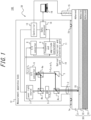
- FIG. 1 is a diagram illustrating a schematic configuration of a measurement system 100 that includes a measurement apparatus 20 according to an embodiment.
- the measurement system 100 includes the measurement apparatus 20 and a terminal apparatus 16.
- the measurement system 100 measures the adhesive strength between layers in a sample 30 composed of a plurality of plate-shaped layers.
- the sample 30 includes an adherend 33 as a third layer, an adhesive 32 as a second layer, and an adherend 31 as a first layer, stacked in this order from the bottom to the top of the page.
- the adherends 31, 33 are resins having the shape of plates adhered to each other by the adhesive 32 provided in between.
- the adherends 31, 33 may, for example, be made of polypropylene or polyethylene.
- the material of the adhesive 32 may be any material that adheres the adherends 31, 33, such as a water-based adhesive, a solvent-based adhesive, a chemical reaction-based adhesive, or a hot-melt adhesive.
- the surfaces of the adherends 31, 33 and adhesive 32 all have a planar shape extending in the horizontal direction, and the adherend 33, adhesive 32, and adherend 31 are stacked in this order from the bottom to the top in the vertical direction, but the shape and arrangement of the sample 30 are not limited to this example.
- the surfaces of the adherends 31, 33 and the adhesive 32 may be curved.
- the surface of at least one of the adherends 31, 33 and the adhesive 32 may be arranged to have a certain inclination with respect to the horizontal plane.
- the sample 30 may, for example, be an aircraft chassis or a wall surface of a building.
- the measurement apparatus 20 includes a measurement apparatus body 12 and a vibrator 15.
- the measurement apparatus body 12 and the vibrator 15 are placed on the surface of the adherend 31.
- the measurement apparatus body 12 is arranged vertically above the measurement target portion 35 in the sample 30, irradiates electromagnetic waves toward the sample 30, and analyzes the reflected waves from the sample 30 to measure the adhesive strength at the measurement target portion 35.
- the measurement target portion 35 is within the range of the adhesive 32 between the adherends 31, 33.
- the vibrator 15 is an apparatus that applies vibration to the sample 30 when the measurement apparatus body 12 transmits and receives electromagnetic waves.
- the vibrator 15 may, for example, apply vibration to the sample 30 by outputting sound waves, including ultrasonic waves.
- the vibrator 15 may, for example, vibrate the sample 30 by outputting sound waves using a phased array or by ablation of the material by a laser.
- FIG. 1 illustrates an example of applying vibration to the sample 30 by contacting the adherend 31, which is the surface irradiated by the laser
- the vibrator 15 may apply vibration to the sample 30 from any location.
- the vibrator 15 may apply vibration to the sample 30 from the adherend 33 located on the opposite side from the irradiated surface, or from the side of the sample 30.
- the vibrator 15 may vibrate only a specific portion of the sample, such as by using a phased array or the like to scan, in the depth direction, the position where the measurement target portion 35 is located.
- FIG. 1 illustrates one vibrator 15 applying vibration to the sample 30, a plurality of vibrators 15 may apply vibration to the sample 30.
- the measurement apparatus body 12 is equipped with movable parts 1 (1a, 1b), an optical part 10, an electrical and electronic part 11, a controller 13, and a data processor 14.
- the movable parts 1 (1a, 1b) include any movable structure that can improve the portability of the measurement apparatus body 12.
- the movable parts 1 (1a, 1b) may include a tire attached to the measurement apparatus body 12.
- the measurement apparatus body 12 can be moved over the surface of the adherend 31 by tires or the like forming the movable parts 1 (1a, 1b).
- the movable parts 1 (1a, 1b) move the measurement apparatus body 12 to enable scanning of the irradiation position of the electromagnetic waves toward the sample 30.
- the optical part 10 irradiates electromagnetic waves toward the sample 30, receives reflected waves from the sample 30, and outputs the reflected waves as an electric signal to the electrical and electronic part 11.
- the optical part 10 is described below as including an optical system for measuring the frequency, amplitude, and the like of vibration at the measurement target portion 35 by optical Doppler measurement, but the method for measuring the frequency, amplitude, and the like of vibration is not limited to this case.
- the measurement apparatus 20 may simply measure the frequency, amplitude, and the like of the vibration from the phase displacement of the reflected waves in a case in which the amplitude of the vibration at the measurement target portion 35 is greater than a predetermined value, or a case in which the frequency of the vibration is greater than a predetermined value.
- the optical part 10 includes a lens 2, a mirror 3, beam splitters 4 (4a, 4b, 4c), an acousto-optical element (acousto-optics modulator, hereinafter “AOM”) 5, a photoelectric (optical signal/electrical signal, hereinafter “O/E”) converter 6, and a laser light source 7.
- AOM acousto-optical element
- O/E photoelectric (optical signal/electrical signal, hereinafter "O/E”) converter 6
- laser light source 7 a laser light source 7.
- the laser light source 7 as an electromagnetic wave output source outputs a laser as an electromagnetic wave.
- the laser light source 7 may be configured by a light-emitting device capable of outputting a laser in a frequency band closer to the frequency band that is highly transmissive with respect to the resin forming the adherend 31.
- the bandwidth of the laser may, for example, be approximately 0.1 THz to 10 THz or may be microwaves, millimeter waves, or terahertz waves.
- the frequency of the laser outputted by the laser light source 7 is denoted as f.
- the signal wave of the laser outputted by the laser light source 7 acts as a carrier wave to transmit information indicating the vibration of the measurement target portion 35 due to the vibrator 15.
- the laser outputted from the laser light source 7 is split in two at the beam splitter 4b.
- One of the lasers split in two at the beam splitter 4b is guided to the AOM 5, and the other laser is guided to the beam splitter 4a.
- the beam splitters 4 (4a, 4b, 4c) may, for example, be one-way mirrors.
- the AOM 5 displaces the frequency f of the laser inputted through the beam splitter 4b to a frequency f + f off .
- the offset frequency f off is selected from a range of values such that a laser with frequency f + f off passes through the resin forming the adherend 31.
- the laser with the frequency displaced in the AOM 5 is guided to the beam splitter 4c.
- the laser inputted from the AOM 5 to the beam splitter 4c passes through the beam splitter 4c, is focused by the lens 2, and is incident on the adherend 31.
- the laser incident on the adherend 31 passes through the adherend 31 and is reflected at the measurement target portion 35 in the adhesive 32.
- the reflected wave contains a frequency component of f + f off ⁇ f d , which reflects the vibration of the measurement target portion 35.
- fa is the change in frequency of the laser displaced by the vibration of the measurement target portion 35 and is equivalent to the vibration frequency of the measurement target portion 35.
- the reflected wave reflected at the measurement target portion 35 is focused by the lens 2 and is incident on the beam splitter 4c.
- the lens 2 focuses both the laser as the incident wave irradiated toward the sample 30 and the reflected wave from the sample 30, but separate lenses may be provided respectively for the incident wave and the reflected wave.
- the reflected wave incident on the beam splitter 4c is reflected at the beam splitter 4c and guided to the mirror 3.
- the mirror 3 reflects the inputted reflected wave and guides the reflected wave to the beam splitter 4a.
- the reflected wave that contains the frequency component of f + f off ⁇ f d and is guided to the beam splitter 4a passes through the beam splitter 4a and is guided to the O/E converter 6.
- the laser of frequency f guided from the beam splitter 4b to the beam splitter 4a is reflected at the beam splitter 4a and guided to the O/E converter 6.
- the O/E converter 6 converts the inputted optical signal to a photoelectric signal and outputs a current signal. Since the polarity of the laser outputted from the laser light source 7 is inverted upon reflection by the measurement target portion 35, the frequency f component of the reflected wave, which contains the frequency components of f + f off ⁇ f d , and the frequency f component of the laser cancel each other out in the O/E converter 6. Therefore, the O/E converter 6 outputs a current signal representing the frequency f off ⁇ f d . In the present embodiment, the optical part 10 thus provokes interference between the reflected light, which is subjected to a frequency shift by the vibration of the AOM 5 and the sample 30, and the laser as a reference light outputted from the laser light source 7.
- the optical part 10 thereby detects a signal pertaining to the vibration of the sample 30 by a heterodyne method.
- the detection of signals pertaining to the vibration of the sample 30 is not limited to such a heterodyne method.
- the mirror 3 instead of the AOM 5, the mirror 3 may be vibrated at a frequency f off so that the reflected wave from the measurement target portion 35 includes a frequency component varied by f off .
- the O/E converter 6 outputs a current signal including a frequency component of f off ⁇ f d to the electrical and electronic part 11.
- the electrical and electronic part 11 analyzes the current signal of frequency f off ⁇ f d inputted from the O/E converter 6 of the optical part 10 to calculate the frequency and amplitude of the vibration at the measurement target portion 35.
- the electrical and electronic part 11 includes an F/V (Frequency/Voltage) converter 8 and a frequency and amplitude calculator 9.
- the F/V converter 8 outputs a voltage signal corresponding to the frequency f off ⁇ f d of the current signal inputted from the O/E converter 6 to the frequency and amplitude calculator 9.
- the frequency and amplitude calculator 9 calculates the frequency, amplitude, and the like of the vibration at the measurement target portion 35 from the voltage signal inputted from the F/V converter 8.
- the frequency and amplitude calculator 9 can measure ⁇ by performing frequency modulation (FM) on the current i outputted from the O/E converter 6, calculating the frequency f off + ⁇ of the current i, and obtaining the difference from the known offset frequency f off .
- FM frequency modulation
- V 0 the amplitude of the speed of the measurement target portion 35 that is vibrating
- ⁇ the wavelength of the light source
- ⁇ is indicated by Mathematical Expression 1.
- ⁇ ⁇ 4 ⁇ f d V 0 cos 2 ⁇ f d t ⁇
- the change in frequency f d is identical to the frequency of the vibration of the measurement target portion 35.
- the frequency and amplitude calculator 9 can determine the frequency f d of the vibration of the measurement target portion 35 based on the frequency of ⁇ . Furthermore, since the change in frequency ⁇ is proportional to the moving speed of the measurement target portion 35, the frequency and amplitude calculator 9 can calculate the amplitude of the measurement target portion 35 by integrating ⁇ .
- the measurement apparatus 20 measures the frequency, amplitude, and the like of the vibration in the measurement target portion 35 directly below the points and analyzes the measured data.
- the data processor 14 of the measurement apparatus body 12 is an arithmetic unit that performs arithmetic processing of such data.
- the controller 13 controls the operation of each component of the measurement apparatus 20.
- the controller 13 may control the operations related to the irradiation of the laser by the laser light source 7, vibration of the vibrator 15, and analysis of the measurement data by the data processor 14.
- the measurement apparatus 20 may be capable of specifying in advance the range over which the measurement apparatus body 12 scans the adherend 31 in order to measure the frequency, amplitude, and the like of the vibration at a plurality of measurement target portions 35 corresponding to a plurality of points.
- the controller 13 may control the operation of the movable parts 1 (1a, 1b) to move the measurement apparatus body 12 to each point where measurement is to be performed and may measure the frequency, amplitude, and the like of vibration at the measurement target portion 35 corresponding to each point.
- the controller 13 includes one or more processors.
- the "processor” in an embodiment is a general-purpose processor or a dedicated processor specialized for particular processing, but these examples are not limiting.
- the functions of the measurement apparatus 20 may be achieved by a processor included in the controller 13 executing a program that can be used to cause the measurement system 100 according to the present embodiment to function.
- the terminal apparatus 16 is an information processing apparatus that accepts instruction input from a user regarding the operation of the measurement apparatus 20.
- the terminal apparatus 16 may be achieved by a general-purpose apparatus, such as a personal computer (PC), tablet, or smartphone, or by a dedicated apparatus.
- PC personal computer
- the terminal apparatus 16 Upon receiving an instruction input from the user, the terminal apparatus 16 issues a measurement execution command corresponding to the content of the instruction input and outputs the command to the data processor 14 of the measurement apparatus 20.
- the data processor 14 outputs the inputted measurement execution command to the controller 13.
- the controller 13 controls the operation of each component of the measurement apparatus 20, including setting, starting, and stopping the laser light source 7 and the vibrator 15, according to the measurement execution command.
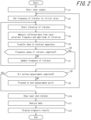
- FIG. 2 is a flowchart illustrating an example of measurement procedures using the measurement apparatus 20 in FIG. 1 .
- FIG. 2 illustrates an example of an operational procedure for measuring adhesive strength by switching the vibration frequency of the vibrator 15 among a plurality of values at each of a plurality of measurement points on the adherend 31 and detecting the frequency, amplitude, and the like of the vibration at the measurement target portion 35 for each vibration frequency.
- the measurement apparatus 20 may measure the adhesive strength by detecting the frequency, amplitude, and the like of the vibration at the measurement target portion 35 in the case of applying vibration at each of the frequencies of 10 kHz, 15 kHz, and 20 kHz at each of a predetermined plurality of measurement points.
- the range of such vibration frequencies may, for example, be determined according to the difference between the modulus of elasticity of the material (for example, the adherends 31, 33) and the modulus of elasticity of the adhesive 32.
- the operation of the measurement apparatus 20 described with reference to FIG. 2 corresponds to one measurement method according to the present embodiment.
- the operation of each step in FIG. 2 is performed based on control by the controller 13.
- a program for causing a computer to execute the measurement method according to the present embodiment may include each of the steps illustrated in FIG. 2 .
- step S1 the controller 13 controls the laser light source 7 to output a laser.
- step S2 the controller 13 sets the frequency of the vibrator 15 to a preset initial value.
- the controller 13 may set 10 kHz as the initial value of the frequency of the vibrator 15.
- step S3 the controller 13 initiates the output of vibration by the vibrator 15 according to the set vibration frequency.
- step S4 the controller 13 measures the reflected wave, from the sample 30, of the laser that was outputted from the laser light source 7 and whose frequency was displaced in the AOM 5 to calculate the frequency, amplitude, and the like of the vibration at the measurement target portion 35.
- the controller 13 may calculate the frequency, amplitude, and the like of the vibration at the measurement target portion 35 by optical Doppler measurement.
- step S5 the controller 13 transfers data on the calculated frequency, amplitude, and the like of the vibration to the terminal apparatus 16.
- step S6 the controller 13 determines whether the predetermined frequency sweep of the vibrator 15 has been completed at that measurement point. For example, the controller 13 may determine that the sweep has been completed in a case in which measurement based on vibration at 10 kHz, 15 kHz, and 20 kHz frequencies is complete at that measurement point. In a case in which the sweep has been completed (YES in step S6), the controller 13 proceeds to step S8. Otherwise (NO in step S6), the controller 13 proceeds to step S7.
- step S7 the controller 13 updates the frequency of the vibrator 15 to a vibration frequency for which measurement has not yet been performed at that measurement point. After completing the process of step S7, the controller 13 returns to step S3 to continue the process.
- step S8 the controller 13 determines whether all of the surface measurement has been completed, i.e., whether the measurement for each of the predetermined plurality of vibration frequencies has been completed for all of the predetermined measurement points. In a case in which all of the surface measurement has been completed (YES in step S8), the controller 13 proceeds to step S10. Otherwise (NO in step S8), the controller 13 proceeds to step S9.
- step S9 the controller 13 moves the measurement apparatus body 12 to the next measurement point at which measurement has not yet been performed.
- the controller 13 may operate the movable parts 1 (1a, 1b) or may, for example, provide notification via a display of the terminal apparatus 16, by audio output, or the like prompting the user to move the measurement apparatus body 12.
- the controller 13 returns to step S2 to continue the process.
- step S10 the controller 13 stops operation of the laser light source 7 and the vibrator 15.
- step S11 the controller 13 analyzes each piece of data obtained by the processes in steps S1 to S9 and measures the adhesive strength at each measurement point.
- vibration characteristics such as the frequency or amplitude
- the vibration at the interface thereof is expected to be nonlinear vibration different than the vibration of the vibrator 15, due to closings or openings.
- the controller 13 therefore determines the adhesive strength of a measurement target portion 35 based on the characteristics, such as the frequency or amplitude, of the vibration of the measurement target portion 35.
- the controller 13 can, for example, determine that the adhesive strength of a certain measurement target portion 35 is weak in a case in which the value of the frequency, amplitude, or the like of the vibration of the measurement target portion 35 is significantly different from the frequency, amplitude, or the like of the vibration of another measurement target portion 35. Specifically, the controller 13 can, for example, acquire the average value and standard deviation ⁇ of the frequency, amplitude, or the like of the vibration of the measurement target portion 35 corresponding to each measurement point and determine that the adhesive strength of a measurement target portion 35 is weak if the value of its frequency, amplitude, or the like is at least a certain value (for example, 2 ⁇ ) away from the average value.
- a certain value for example, 2 ⁇
- the controller 13 may mark the measurement target portions 35 whose frequency, amplitude, or other value of vibration is at least a certain value away from the average value for each frequency of the vibrator 15. The controller 13 can then determine that the adhesive strength is weak for a measurement target portion 35 marked for at least one vibration frequency of the vibrator 15. Alternatively, the controller 13 can determine that the adhesive strength is weak for a measurement target portion 35 marked for at least two, or all, vibration frequencies of the vibrator 15.
- the controller 13 may determine the adhesive strength of the measurement target portion 35 by comparing the measured value of the frequency, amplitude, or the like of vibration of the measurement target portion 35 with the information, stored in the memory apparatus in advance, indicating the relationship between the characteristics and the adhesive strength.
- the measurement apparatus 20 may, in this case as well, switch the vibration frequency of the vibrator 15 among a plurality of values and detect the frequency and amplitude of the vibration at the measurement target portion 35 for each vibration frequency to further improve the accuracy for determining the adhesive strength.
- the measurement apparatus 20 may use phase information to determine the adhesive strength.
- step S12 the controller 13 displays an image illustrating the measurement results (diagnosis results) on a display of the terminal apparatus 16.
- the controller 13 may display values indicating the adhesive strength at each measurement point, the marked measurement target portions 35, and the like.
- the controller 13 ends the process of the flowchart.
- FIG. 2 illustrates an example of starting the vibration of the vibrator 15 in step S3 after starting the output of the laser in step S1, the measurement apparatus 20 may start the vibration of the vibrator 15 before starting the output of the laser.
- Closings and openings are generated by vibration, for example, in a case in which the layers forming the sample 30 are in contact but not adhered. This results in complex vibration behavior, and the spectrum of vibration of the measurement target portion 35 will contain various frequency components.
- the measurement apparatus 20 uses this property for highly accurate measurement of the adhesive strength at the measurement target portion 35.
- the controller 13 may also cause a p-polarized laser to be outputted from the laser light source 7 toward the sample 30 at Brewster's angle as the electromagnetic wave. This can exclude the effect of reflected waves from the surface of the sample 30, and the measurement apparatus 20 can measure the adhesive strength of the measurement target portion 35 with even higher accuracy.
- the controller 13 may output the electromagnetic wave toward the sample 30 subjected to vibration at a first vibration frequency as the predetermined vibration frequency.
- the controller 13 may calculate a first frequency or a first amplitude, which is the frequency or the amplitude of vibration of the measurement target portion 35, based on the reflected wave of the electromagnetic wave from the measurement target portion 35 of the sample 30 subjected to vibration at the first vibration frequency.
- the controller 13 may output the electromagnetic wave toward the sample 30 subjected to vibration at a second vibration frequency as the predetermined vibration frequency.
- the controller 13 may calculate a second frequency or a second amplitude, which is the frequency or the amplitude of vibration of the measurement target portion 35, based on the reflected wave of the electromagnetic wave from the measurement target portion 35 of the sample 30 subjected to vibration at the second vibration frequency.
- the controller 13 may then measure the adhesive strength of the measurement target portion 35 based on at least one of the first frequency and the second frequency, and the first amplitude and the second amplitude. In this way, the measurement apparatus 20 may use the total of the frequency or amplitude of the reflected wave from the sample 30 subjected to vibration at the first vibration frequency and the frequency or amplitude of the reflected wave from the sample 30 subjected to vibration at the second vibration frequency.
- the measurement apparatus 20 can therefore measure the adhesive strength of the measurement target portion 35 with even higher accuracy.
- the controller 13 may output an electromagnetic wave toward each measurement target portion 35 in a plurality of measurement target portions 35 at the interface between the first layer and the second layer and may receive a reflected wave of the electromagnetic wave from each measurement target portion 35 in the plurality of measurement target portions 35.
- the controller 13 may analyze, for each measurement target portion 35 in the plurality of measurement target portions 35, the reflected wave from the measurement target portion 35 to calculate a frequency or an amplitude of vibration of the measurement target portion 35.
- the controller 13 may measure, for each measurement target portion 35 in the plurality of measurement target portions 35, an adhesive strength of the measurement target portion 35 based on a comparison between the frequency or the amplitude of the vibration of the measurement target portion 35 and an average value of the frequency or the amplitude of the vibration of the plurality of measurement target portions 35.
- the measurement apparatus 20 measures the frequency or amplitude of the vibration of the plurality of measurement target portions 35 and measures the adhesive strength of a certain measurement target portion 35 based on a comparison with the frequency or the amplitude of the vibration of the plurality of measurement target portions 35.
- the measurement apparatus 20 can thereby further increase the measurement accuracy.
- the controller 13 may output an electromagnetic wave of a first frequency f 1 from a first electromagnetic wave output source (laser light source 7) toward the sample 30, the second layer of the sample 30 being provided with an additive that increases reflectance of the electromagnetic wave of the first frequency f 1 .
- a first electromagnetic wave output source laser light source 7
- This enables the measurement apparatus 20 to receive reflected waves with high reflection intensity from the second layer and to measure, with even higher accuracy, the adhesive strength of the measurement target portion 35 located at the interface between the first layer and the second layer.
- the controller 13 may output an electromagnetic wave of a second frequency f 2 from a second electromagnetic wave output source toward the sample 30, the sample 30 further including a third layer (for example, the adherend 33) that is adjacent to the second layer and is provided with an additive that increases reflectance of the electromagnetic wave of the second frequency f 2 .
- the controller 13 may receive a reflected wave of the electromagnetic wave of the second frequency f 2 from a measurement target portion 35 at the interface between the second layer and the third layer.
- the controller 13 may calculate a frequency or an amplitude of vibration of the measurement target portion 35 at the interface between the second layer and the third layer based on the reflected wave of the second frequency f 2 .
- the controller 13 may measure an adhesive strength of the measurement target portion 35 at the interface between the second layer and the third layer based on the frequency or the amplitude of the vibration of the measurement target portion 35 at the interface between the second layer and the third layer. In this way, the measurement apparatus 20 may irradiate an electromagnetic wave of the second frequency f 2 toward the sample 30 that includes the third layer with an additive that increases the reflectance of the electromagnetic wave of the second frequency f 2 . The measurement apparatus 20 may then measure the adhesive strength of the measurement target portion 35 at the interface between the second layer and the third layer based on the reflected wave. This enables the measurement apparatus 20 to receive reflected waves with high reflection intensity from the third layer and to measure, with high accuracy, the adhesive strength of the measurement target portion 35 located at the interface between the second layer and the third layer.
- the present disclosure is not limited to the above embodiments.
- a plurality of blocks described in the block diagrams may be integrated, or a block may be divided.
- the plurality of steps described in the flowcharts may be executed in chronological order in accordance with the description, the plurality of steps may be executed in parallel or in a different order according to the processing capability of the apparatus that executes each step, or as required.
- Other modifications can be made without departing from the spirit of the present disclosure.
Landscapes
- Physics & Mathematics (AREA)
- Health & Medical Sciences (AREA)
- General Physics & Mathematics (AREA)
- Life Sciences & Earth Sciences (AREA)
- Chemical & Material Sciences (AREA)
- Analytical Chemistry (AREA)
- Biochemistry (AREA)
- General Health & Medical Sciences (AREA)
- Immunology (AREA)
- Pathology (AREA)
- Spectroscopy & Molecular Physics (AREA)
- Toxicology (AREA)
- Optics & Photonics (AREA)
- Investigating Or Analyzing Materials By The Use Of Ultrasonic Waves (AREA)
Abstract
Description
- The present application claims priority to
Japanese Patent Application No. 2021-181510 filed on November 5, 2021 - The present disclosure relates to a measurement apparatus and a measurement method.
- Non-destructive testing refers to a testing technique to examine the state of defects or deterioration inside or on the surface of a sample without destroying the sample. Patent Literature (PTL) 1 describes a technique for nondestructive testing to determine the adhesive strength between layers of a multilayer sample.
- PTL 1:
JP 5684819 B2 - Conventional configurations have room for improvement, however, in the measurement accuracy of the adhesive strength between layers.
- It is an aim of the present disclosure to provide a measurement apparatus and a measurement method capable of improving the measurement accuracy of the adhesive strength between layers.
- A measurement apparatus according to several embodiments includes a controller configured to output an electromagnetic wave from an electromagnetic wave output source toward a sample that has a first layer and a second layer adj acent to each other and is subj ected to vibration at a predetermined vibration frequency, receive a reflected wave of the electromagnetic wave from a measurement target portion at an interface between the first layer and the second layer, calculate a frequency or an amplitude of vibration of the measurement target portion based on the reflected wave, and measure an adhesive strength of the measurement target portion based on the frequency or the amplitude of vibration of the measurement target portion calculated based on the reflected wave. In this way, the measurement apparatus can measure the adhesive strength between layers with high accuracy, since the adhesive strength is measured by acquiring the frequency or amplitude of vibration of the measurement target portion while the degree of the adhesive strength at the interface is brought to light by the vibration.
- In the measurement apparatus according to an embodiment, the controller is configured to measure the adhesive strength of the measurement target portion based on a frequency spectrum of the vibration of the measurement target portion in a frequency band that includes a different frequency than the vibration frequency. In this way, the measurement apparatus can measure the adhesive strength of the measurement target portion with even higher accuracy by referring to the frequency spectrum of the vibration of the measurement target portion in a frequency band that includes a different frequency than the vibration frequency of the sample.
- In the measurement apparatus according to an embodiment, the controller is configured to calculate the frequency or the amplitude of vibration of the measurement target portion by performing a Doppler measurement of the reflected wave. The measurement apparatus can reduce the effect of background noise by using Doppler measurement and can measure the adhesive strength of the measurement target portion with even higher accuracy.
- In the measurement apparatus according to an embodiment, the controller is configured to cause a p-polarized laser from a laser light source to be outputted toward the sample at Brewster's angle as the electromagnetic wave. This can exclude the effect of reflected waves from the surface of the sample, and the measurement apparatus can measure the adhesive strength of the measurement target portion with even higher accuracy.
- In the measurement apparatus according to an embodiment, the controller is configured to output the electromagnetic wave toward the sample subjected to vibration at a first vibration frequency as the predetermined vibration frequency and calculate a first frequency or a first amplitude, which is the frequency or the amplitude of vibration of the measurement target portion, based on the reflected wave of the electromagnetic wave from the measurement target portion of the sample subjected to vibration at the first vibration frequency, output the electromagnetic wave toward the sample subjected to vibration at a second vibration frequency as the predetermined vibration frequency and calculate a second frequency or a second amplitude, which is the frequency or the amplitude of vibration of the measurement target portion, based on the reflected wave of the electromagnetic wave from the measurement target portion of the sample subjected to vibration at the second vibration frequency, and measure the adhesive strength of the measurement target portion based on at least one of the first frequency and the second frequency, and the first amplitude and the second amplitude. In this way, the measurement apparatus may use the total of the frequency or amplitude of the reflected wave from the sample subjected to vibration at the first vibration frequency and the frequency or amplitude of the reflected wave from the sample subjected to vibration at the second vibration frequency. The measurement apparatus can therefore measure the adhesive strength of the measurement target portion with even higher accuracy.
- In the measurement apparatus according to an embodiment, there are a plurality of measurement target portions at the interface between the first layer and the second layer, and the controller is configured to output an electromagnetic wave toward each measurement target portion in a plurality of measurement target portions at the interface between the first layer and the second layer, receive a reflected wave of the electromagnetic wave from each measurement target portion in the plurality of measurement target portions, analyze, for each measurement target portion in the plurality of measurement target portions, the reflected wave from the measurement target portion to calculate a frequency or an amplitude of vibration of the measurement target portion, and measure, for each measurement target portion in the plurality of measurement target portions, an adhesive strength of the measurement target portion based on a comparison between the frequency or the amplitude of vibration of the measurement target portion and an average value of the frequency or the amplitude of vibration of the plurality of measurement target portions. In this way, the measurement apparatus measures the frequency or amplitude of vibration of the plurality of measurement target portions and measures the adhesive strength of a certain measurement target portion based on a comparison with the frequency or the amplitude of vibration of the plurality of measurement target portions. The measurement apparatus can thereby further increase the measurement accuracy.
- In the measurement apparatus according to an embodiment, the controller is configured to output an electromagnetic wave of a first frequency from a first electromagnetic wave output source toward the sample, the second layer of the sample being provided with an additive that increases reflectance of the electromagnetic wave of the first frequency. This enables the measurement apparatus to receive reflected waves with high reflection intensity from the second layer and to measure, with even higher accuracy, the adhesive strength of the measurement target portion located at the interface between the first layer and the second layer.
- In the measurement apparatus according to an embodiment, the controller is configured to output an electromagnetic wave of a second frequency from a second electromagnetic wave output source toward the sample, the sample further including a third layer that is adjacent to the second layer and is provided with an additive that increases reflectance of the electromagnetic wave of the second frequency, receive a reflected wave of the electromagnetic wave of the second frequency from a measurement target portion at an interface between the second layer and the third layer, calculate a frequency or an amplitude of vibration of the measurement target portion at the interface between the second layer and the third layer based on the reflected wave of the second frequency, and measure an adhesive strength of the measurement target portion at the interface between the second layer and the third layer based on the frequency or the amplitude of vibration of the measurement target portion at the interface between the second layer and the third layer. This enables the measurement apparatus to receive reflected waves with high reflection intensity from the third layer and to measure, with even higher accuracy, the adhesive strength of the measurement target portion located at the interface between the second layer and the third layer.
- In the measurement apparatus according to an embodiment, the controller is configured to output, from a third electromagnetic wave output source, an electromagnetic wave of a third frequency that is reflected by a specific foreign object, and determine that the specific foreign object is present in the sample in response to reception of a reflected wave of the electromagnetic wave of the third frequency from the sample. The measurement apparatus can therefore determine whether a foreign object is present in the sample.
- A measurement method according to several embodiments is a measurement method of a measurement apparatus, the measurement method including outputting, by a controller, an electromagnetic wave from an electromagnetic wave output source toward a sample that has a first layer and a second layer adjacent to each other and is subjected to vibration at a predetermined vibration frequency, receiving, by the controller, a reflected wave of the electromagnetic wave from a measurement target portion at an interface between the first layer and the second layer, calculating, by the controller, a frequency or an amplitude of vibration of the measurement target portion based on the reflected wave, and measuring, by the controller, an adhesive strength of the measurement target portion based on the frequency or the amplitude of vibration of the measurement target portion calculated based on the reflected wave. In this way, the measurement method can measure the adhesive strength between layers with high accuracy, since the adhesive strength is measured by acquiring the frequency or amplitude of vibration of the measurement target portion while the degree of the adhesive strength at the interface is brought to light by the vibration.
- According to an embodiment of the present disclosure, the measurement accuracy of the adhesive strength between layers can be improved.
- In the accompanying drawings:
-
FIG. 1 is a diagram illustrating the schematic configuration of a measurement system including a measurement apparatus according to one embodiment; -
FIG. 2 is a flowchart illustrating an example of measurement procedures using the measurement apparatus inFIG. 1 ; -
FIG. 3 is a diagram schematically illustrating the output of a laser, from the measurement apparatus inFIG. 1 , at Brewster's angle toward a sample; -
FIG. 4A is a diagram schematically illustrating reflection of a laser from a sample containing an adherend provided with an additive; -
FIG. 4B is a diagram schematically illustrating reflection of a laser from a sample containing an adherend provided with an additive; and -
FIG. 4C is a diagram schematically illustrating reflection of a laser from a sample containing an adherend provided with an additive. - A system according to a Comparative Example described in
PTL 1 outputs electromagnetic radiation toward a multilayer sample and analyzes the electromagnetic radiation reflected by or transmitted through the sample to determine the adhesive strength between the layers of the multilayer sample. The system according to the Comparative Example includes a transmitter that outputs electromagnetic radiation toward a sample, a receiver that receives electromagnetic radiation reflected by or transmitted through the sample, and a data collection device. The system according to the Comparative Example determines the adhesive strength between the first layer and the second layer based on the waveform of the electromagnetic radiation reflected by or transmitted through the sample. - However, since the system according to the Comparative Example outputs electromagnetic radiation from the outside toward a stationary sample and determines the adhesive strength based on the waveform of the reflected electromagnetic radiation and the like, it is difficult to accurately distinguish between the cases in which the first layer and second layer are weakly and strongly adhered to each other. Therefore, the system according to the Comparative Example has difficulty in measuring the adhesive strength between the layers of a sample with high accuracy. To address this issue, the present disclosure describes a measurement apparatus and a measurement method capable of measuring the adhesive strength between layers with high accuracy.
- Embodiments of the present disclosure are now described with reference to the drawings. Portions having an identical configuration or function in the drawings are labeled with the same reference signs. In the explanation of the embodiments, a redundant description of identical portions may be omitted or simplified as appropriate.
- The measurement apparatus according to the present embodiment irradiates electromagnetic waves toward a sample, as a measurement target consisting of multiple layers, while vibrating the sample. From the reflected wave, the measurement apparatus detects the frequency, amplitude, and the like regarding the vibration of the interface at a measurement point and measures the adhesive strength at the interface of the adherend. In this way, the measurement apparatus according to the present embodiment measures the adhesive strength according to the characteristics of the vibration at the measurement point as detected from the reflected wave from the vibrating sample. The measurement apparatus can thereby measure the adhesive strength between layers with high accuracy.
-
FIG. 1 is a diagram illustrating a schematic configuration of ameasurement system 100 that includes ameasurement apparatus 20 according to an embodiment. Themeasurement system 100 includes themeasurement apparatus 20 and aterminal apparatus 16. Themeasurement system 100 measures the adhesive strength between layers in asample 30 composed of a plurality of plate-shaped layers. In the example inFIG. 1 , thesample 30 includes anadherend 33 as a third layer, an adhesive 32 as a second layer, and anadherend 31 as a first layer, stacked in this order from the bottom to the top of the page. Theadherends adherends adherends adherends adherend 33, adhesive 32, andadherend 31 are stacked in this order from the bottom to the top in the vertical direction, but the shape and arrangement of thesample 30 are not limited to this example. For example, the surfaces of theadherends adherends sample 30 may, for example, be an aircraft chassis or a wall surface of a building. - The
measurement apparatus 20 includes ameasurement apparatus body 12 and avibrator 15. In the example inFIG. 1 , themeasurement apparatus body 12 and thevibrator 15 are placed on the surface of theadherend 31. Themeasurement apparatus body 12 is arranged vertically above themeasurement target portion 35 in thesample 30, irradiates electromagnetic waves toward thesample 30, and analyzes the reflected waves from thesample 30 to measure the adhesive strength at themeasurement target portion 35. Themeasurement target portion 35 is within the range of the adhesive 32 between theadherends - The
vibrator 15 is an apparatus that applies vibration to thesample 30 when themeasurement apparatus body 12 transmits and receives electromagnetic waves. Thevibrator 15 may, for example, apply vibration to thesample 30 by outputting sound waves, including ultrasonic waves. Specifically, thevibrator 15 may, for example, vibrate thesample 30 by outputting sound waves using a phased array or by ablation of the material by a laser. AlthoughFIG. 1 illustrates an example of applying vibration to thesample 30 by contacting theadherend 31, which is the surface irradiated by the laser, thevibrator 15 may apply vibration to thesample 30 from any location. For example, thevibrator 15 may apply vibration to thesample 30 from theadherend 33 located on the opposite side from the irradiated surface, or from the side of thesample 30. Alternatively, thevibrator 15 may vibrate only a specific portion of the sample, such as by using a phased array or the like to scan, in the depth direction, the position where themeasurement target portion 35 is located. AlthoughFIG. 1 illustrates onevibrator 15 applying vibration to thesample 30, a plurality ofvibrators 15 may apply vibration to thesample 30. - The
measurement apparatus body 12 is equipped with movable parts 1 (1a, 1b), anoptical part 10, an electrical andelectronic part 11, acontroller 13, and adata processor 14. The movable parts 1 (1a, 1b) include any movable structure that can improve the portability of themeasurement apparatus body 12. For example, the movable parts 1 (1a, 1b) may include a tire attached to themeasurement apparatus body 12. Themeasurement apparatus body 12 can be moved over the surface of theadherend 31 by tires or the like forming the movable parts 1 (1a, 1b). The movable parts 1 (1a, 1b) move themeasurement apparatus body 12 to enable scanning of the irradiation position of the electromagnetic waves toward thesample 30. - The
optical part 10 irradiates electromagnetic waves toward thesample 30, receives reflected waves from thesample 30, and outputs the reflected waves as an electric signal to the electrical andelectronic part 11. As an example, theoptical part 10 is described below as including an optical system for measuring the frequency, amplitude, and the like of vibration at themeasurement target portion 35 by optical Doppler measurement, but the method for measuring the frequency, amplitude, and the like of vibration is not limited to this case. For example, themeasurement apparatus 20 may simply measure the frequency, amplitude, and the like of the vibration from the phase displacement of the reflected waves in a case in which the amplitude of the vibration at themeasurement target portion 35 is greater than a predetermined value, or a case in which the frequency of the vibration is greater than a predetermined value. Theoptical part 10 includes alens 2, amirror 3, beam splitters 4 (4a, 4b, 4c), an acousto-optical element (acousto-optics modulator, hereinafter "AOM") 5, a photoelectric (optical signal/electrical signal, hereinafter "O/E")converter 6, and alaser light source 7. - In the
optical part 10, thelaser light source 7 as an electromagnetic wave output source outputs a laser as an electromagnetic wave. Thelaser light source 7 may be configured by a light-emitting device capable of outputting a laser in a frequency band closer to the frequency band that is highly transmissive with respect to the resin forming theadherend 31. The bandwidth of the laser may, for example, be approximately 0.1 THz to 10 THz or may be microwaves, millimeter waves, or terahertz waves. Hereafter, the frequency of the laser outputted by thelaser light source 7 is denoted as f. The signal wave of the laser outputted by thelaser light source 7 acts as a carrier wave to transmit information indicating the vibration of themeasurement target portion 35 due to thevibrator 15. - The laser outputted from the
laser light source 7 is split in two at thebeam splitter 4b. One of the lasers split in two at thebeam splitter 4b is guided to theAOM 5, and the other laser is guided to thebeam splitter 4a. The beam splitters 4 (4a, 4b, 4c) may, for example, be one-way mirrors. - The
AOM 5 displaces the frequency f of the laser inputted through thebeam splitter 4b to a frequency f + foff. The offset frequency foff is selected from a range of values such that a laser with frequency f + foff passes through the resin forming theadherend 31. The laser with the frequency displaced in theAOM 5 is guided to thebeam splitter 4c. - The laser inputted from the
AOM 5 to thebeam splitter 4c passes through thebeam splitter 4c, is focused by thelens 2, and is incident on theadherend 31. The laser incident on theadherend 31 passes through theadherend 31 and is reflected at themeasurement target portion 35 in the adhesive 32. Since thesample 30 is subjected to vibration by thevibrator 15, the reflected wave contains a frequency component of f + foff ± fd, which reflects the vibration of themeasurement target portion 35. Here, fa is the change in frequency of the laser displaced by the vibration of themeasurement target portion 35 and is equivalent to the vibration frequency of themeasurement target portion 35. The reflected wave reflected at themeasurement target portion 35 is focused by thelens 2 and is incident on thebeam splitter 4c. In the example inFIG. 1 , thelens 2 focuses both the laser as the incident wave irradiated toward thesample 30 and the reflected wave from thesample 30, but separate lenses may be provided respectively for the incident wave and the reflected wave. - The reflected wave incident on the
beam splitter 4c is reflected at thebeam splitter 4c and guided to themirror 3. Themirror 3 reflects the inputted reflected wave and guides the reflected wave to thebeam splitter 4a. The reflected wave that contains the frequency component of f + foff ± fd and is guided to thebeam splitter 4a passes through thebeam splitter 4a and is guided to the O/E converter 6. On the other hand, the laser of frequency f guided from thebeam splitter 4b to thebeam splitter 4a is reflected at thebeam splitter 4a and guided to the O/E converter 6. - The O/
E converter 6 converts the inputted optical signal to a photoelectric signal and outputs a current signal. Since the polarity of the laser outputted from thelaser light source 7 is inverted upon reflection by themeasurement target portion 35, the frequency f component of the reflected wave, which contains the frequency components of f + foff ± fd, and the frequency f component of the laser cancel each other out in the O/E converter 6. Therefore, the O/E converter 6 outputs a current signal representing the frequency foff ± fd. In the present embodiment, theoptical part 10 thus provokes interference between the reflected light, which is subjected to a frequency shift by the vibration of theAOM 5 and thesample 30, and the laser as a reference light outputted from thelaser light source 7. Theoptical part 10 thereby detects a signal pertaining to the vibration of thesample 30 by a heterodyne method. The detection of signals pertaining to the vibration of thesample 30 is not limited to such a heterodyne method. For example, instead of theAOM 5, themirror 3 may be vibrated at a frequency foff so that the reflected wave from themeasurement target portion 35 includes a frequency component varied by foff. The O/E converter 6 outputs a current signal including a frequency component of foff ± fd to the electrical andelectronic part 11. - The electrical and
electronic part 11 analyzes the current signal of frequency foff ± fd inputted from the O/E converter 6 of theoptical part 10 to calculate the frequency and amplitude of the vibration at themeasurement target portion 35. The electrical andelectronic part 11 includes an F/V (Frequency/Voltage)converter 8 and a frequency andamplitude calculator 9. The F/V converter 8 outputs a voltage signal corresponding to the frequency foff ± fd of the current signal inputted from the O/E converter 6 to the frequency andamplitude calculator 9. The frequency andamplitude calculator 9 calculates the frequency, amplitude, and the like of the vibration at themeasurement target portion 35 from the voltage signal inputted from the F/V converter 8. - Specifically, the frequency and
amplitude calculator 9 can measure Δν by performing frequency modulation (FM) on the current i outputted from the O/E converter 6, calculating the frequency foff + Δν of the current i, and obtaining the difference from the known offset frequency foff. Here, letting t be time, V0 be the amplitude of the speed of themeasurement target portion 35 that is vibrating, and λ be the wavelength of the light source, Δν is indicated byMathematical Expression 1.
measurement target portion 35. Therefore, the frequency andamplitude calculator 9 can determine the frequency fd of the vibration of themeasurement target portion 35 based on the frequency of Δν. Furthermore, since the change in frequency Δν is proportional to the moving speed of themeasurement target portion 35, the frequency andamplitude calculator 9 can calculate the amplitude of themeasurement target portion 35 by integrating Δν. - From a plurality of points on the surface of the
adherend 31, themeasurement apparatus 20 measures the frequency, amplitude, and the like of the vibration in themeasurement target portion 35 directly below the points and analyzes the measured data. Thedata processor 14 of themeasurement apparatus body 12 is an arithmetic unit that performs arithmetic processing of such data. - The
controller 13 controls the operation of each component of themeasurement apparatus 20. For example, thecontroller 13 may control the operations related to the irradiation of the laser by thelaser light source 7, vibration of thevibrator 15, and analysis of the measurement data by thedata processor 14. Themeasurement apparatus 20 may be capable of specifying in advance the range over which themeasurement apparatus body 12 scans theadherend 31 in order to measure the frequency, amplitude, and the like of the vibration at a plurality ofmeasurement target portions 35 corresponding to a plurality of points. In the case in which such a scanning range is specified, thecontroller 13 may control the operation of the movable parts 1 (1a, 1b) to move themeasurement apparatus body 12 to each point where measurement is to be performed and may measure the frequency, amplitude, and the like of vibration at themeasurement target portion 35 corresponding to each point. Thecontroller 13 includes one or more processors. The "processor" in an embodiment is a general-purpose processor or a dedicated processor specialized for particular processing, but these examples are not limiting. The functions of themeasurement apparatus 20 may be achieved by a processor included in thecontroller 13 executing a program that can be used to cause themeasurement system 100 according to the present embodiment to function. - The
terminal apparatus 16 is an information processing apparatus that accepts instruction input from a user regarding the operation of themeasurement apparatus 20. Theterminal apparatus 16 may be achieved by a general-purpose apparatus, such as a personal computer (PC), tablet, or smartphone, or by a dedicated apparatus. Upon receiving an instruction input from the user, theterminal apparatus 16 issues a measurement execution command corresponding to the content of the instruction input and outputs the command to thedata processor 14 of themeasurement apparatus 20. Thedata processor 14 outputs the inputted measurement execution command to thecontroller 13. Thecontroller 13 controls the operation of each component of themeasurement apparatus 20, including setting, starting, and stopping thelaser light source 7 and thevibrator 15, according to the measurement execution command. - Next, details of the operation of the
measurement apparatus 20 are described with reference toFIG. 2. FIG. 2 is a flowchart illustrating an example of measurement procedures using themeasurement apparatus 20 inFIG. 1 .FIG. 2 illustrates an example of an operational procedure for measuring adhesive strength by switching the vibration frequency of thevibrator 15 among a plurality of values at each of a plurality of measurement points on theadherend 31 and detecting the frequency, amplitude, and the like of the vibration at themeasurement target portion 35 for each vibration frequency. For example, themeasurement apparatus 20 may measure the adhesive strength by detecting the frequency, amplitude, and the like of the vibration at themeasurement target portion 35 in the case of applying vibration at each of the frequencies of 10 kHz, 15 kHz, and 20 kHz at each of a predetermined plurality of measurement points. The range of such vibration frequencies may, for example, be determined according to the difference between the modulus of elasticity of the material (for example, theadherends 31, 33) and the modulus of elasticity of the adhesive 32. The operation of themeasurement apparatus 20 described with reference toFIG. 2 corresponds to one measurement method according to the present embodiment. The operation of each step inFIG. 2 is performed based on control by thecontroller 13. A program for causing a computer to execute the measurement method according to the present embodiment may include each of the steps illustrated inFIG. 2 . - In step S1, the
controller 13 controls thelaser light source 7 to output a laser. - In step S2, the
controller 13 sets the frequency of thevibrator 15 to a preset initial value. For example, thecontroller 13 may set 10 kHz as the initial value of the frequency of thevibrator 15. - In step S3, the
controller 13 initiates the output of vibration by thevibrator 15 according to the set vibration frequency. - In step S4, the
controller 13 measures the reflected wave, from thesample 30, of the laser that was outputted from thelaser light source 7 and whose frequency was displaced in theAOM 5 to calculate the frequency, amplitude, and the like of the vibration at themeasurement target portion 35. For example, as mentioned above, thecontroller 13 may calculate the frequency, amplitude, and the like of the vibration at themeasurement target portion 35 by optical Doppler measurement. - In step S5, the
controller 13 transfers data on the calculated frequency, amplitude, and the like of the vibration to theterminal apparatus 16. - In step S6, the
controller 13 determines whether the predetermined frequency sweep of thevibrator 15 has been completed at that measurement point. For example, thecontroller 13 may determine that the sweep has been completed in a case in which measurement based on vibration at 10 kHz, 15 kHz, and 20 kHz frequencies is complete at that measurement point. In a case in which the sweep has been completed (YES in step S6), thecontroller 13 proceeds to step S8. Otherwise (NO in step S6), thecontroller 13 proceeds to step S7. - In step S7, the
controller 13 updates the frequency of thevibrator 15 to a vibration frequency for which measurement has not yet been performed at that measurement point. After completing the process of step S7, thecontroller 13 returns to step S3 to continue the process. - In step S8, the
controller 13 determines whether all of the surface measurement has been completed, i.e., whether the measurement for each of the predetermined plurality of vibration frequencies has been completed for all of the predetermined measurement points. In a case in which all of the surface measurement has been completed (YES in step S8), thecontroller 13 proceeds to step S10. Otherwise (NO in step S8), thecontroller 13 proceeds to step S9. - In step S9, the
controller 13 moves themeasurement apparatus body 12 to the next measurement point at which measurement has not yet been performed. To move themeasurement apparatus body 12, thecontroller 13 may operate the movable parts 1 (1a, 1b) or may, for example, provide notification via a display of theterminal apparatus 16, by audio output, or the like prompting the user to move themeasurement apparatus body 12. After completing the process of step S9, thecontroller 13 returns to step S2 to continue the process. - In step S10, the
controller 13 stops operation of thelaser light source 7 and thevibrator 15. - In step S11, the
controller 13 analyzes each piece of data obtained by the processes in steps S1 to S9 and measures the adhesive strength at each measurement point. In general, when thesample 30 is subjected to vibration, it is considered that there will be a difference in vibration characteristics, such as the frequency or amplitude, between ameasurement target portion 35 that has high adhesive strength and ameasurement target portion 35 that has low adhesive strength. For example, in a case in which theadherends vibrator 15, due to closings or openings. Thecontroller 13 therefore determines the adhesive strength of ameasurement target portion 35 based on the characteristics, such as the frequency or amplitude, of the vibration of themeasurement target portion 35. Thecontroller 13 can, for example, determine that the adhesive strength of a certainmeasurement target portion 35 is weak in a case in which the value of the frequency, amplitude, or the like of the vibration of themeasurement target portion 35 is significantly different from the frequency, amplitude, or the like of the vibration of anothermeasurement target portion 35. Specifically, thecontroller 13 can, for example, acquire the average value and standard deviation σ of the frequency, amplitude, or the like of the vibration of themeasurement target portion 35 corresponding to each measurement point and determine that the adhesive strength of ameasurement target portion 35 is weak if the value of its frequency, amplitude, or the like is at least a certain value (for example, 2σ) away from the average value. At this time, thecontroller 13 may mark themeasurement target portions 35 whose frequency, amplitude, or other value of vibration is at least a certain value away from the average value for each frequency of thevibrator 15. Thecontroller 13 can then determine that the adhesive strength is weak for ameasurement target portion 35 marked for at least one vibration frequency of thevibrator 15. Alternatively, thecontroller 13 can determine that the adhesive strength is weak for ameasurement target portion 35 marked for at least two, or all, vibration frequencies of thevibrator 15. - The
measurement apparatus 20 can determine that the adhesive strength of themeasurement target portion 35 that vibrates with characteristics that differ significantly from the characteristics of the vibration of thevibrator 15 is weak. For example, themeasurement apparatus 20 can determine that the adhesive strength of ameasurement target portion 35 for which the difference in frequency or amplitude from the vibration of thevibrator 15 is equal to or greater than a certain value is weak. Themeasurement apparatus 20 may acquire in advance, and store in a memory apparatus, the relationship between characteristics, such as frequency or amplitude, of the vibration of themeasurement target portion 35 and the adhesive strength for each type ofsample 30, each measurement environment (including the vibration frequency of the vibrator 15), and the like. In this case, thecontroller 13 may determine the adhesive strength of themeasurement target portion 35 by comparing the measured value of the frequency, amplitude, or the like of vibration of themeasurement target portion 35 with the information, stored in the memory apparatus in advance, indicating the relationship between the characteristics and the adhesive strength. Themeasurement apparatus 20 may, in this case as well, switch the vibration frequency of thevibrator 15 among a plurality of values and detect the frequency and amplitude of the vibration at themeasurement target portion 35 for each vibration frequency to further improve the accuracy for determining the adhesive strength. In addition to, or instead of, the frequency and amplitude of the vibration of themeasurement target portion 35, themeasurement apparatus 20 may use phase information to determine the adhesive strength. - In this way, the
controller 13 may acquire a value indicating the adhesive strength at eachmeasurement target portion 35 by, for example, acquiring the difference between a characteristic of vibration at thatmeasurement target portion 35 and a reference vibration characteristic. Such a reference vibration characteristic may, for example, be the average value of a vibration characteristic of othermeasurement target portions 35, a characteristic of the vibration of thevibrator 15, or a value related to a previously learned characteristic. Themeasurement target portion 35 for which the difference between the value indicating the adhesive strength and the reference vibration characteristic is at least a certain value (for example, 2σ) may be marked as a portion at which the adhesive strength is weak. - In step S12, the
controller 13 displays an image illustrating the measurement results (diagnosis results) on a display of theterminal apparatus 16. For example, thecontroller 13 may display values indicating the adhesive strength at each measurement point, the markedmeasurement target portions 35, and the like. After completing the process of step S12, thecontroller 13 ends the process of the flowchart. AlthoughFIG. 2 illustrates an example of starting the vibration of thevibrator 15 in step S3 after starting the output of the laser in step S1, themeasurement apparatus 20 may start the vibration of thevibrator 15 before starting the output of the laser. - As described above, the
measurement apparatus 20 vibrates thesample 30 that is the measurement target while irradiating a laser in the microwave, millimeter wave, or terahertz wave band toward the target, thereby transmitting radiation through theadherend 31, and performs Doppler measurement of the reflection from themeasurement target portion 35 at the adhesive interface to be observed. This enables highly accurate determination of the adhesive state at themeasurement target portion 35. In other words, as in the Comparative Example, it is difficult to determine, in a static state, whether the layers forming thesample 30 are in contact but not adhered. By vibrating thesample 30, themeasurement apparatus 20 brings to light the difference between a state of being in contact but not adhered and a state of being in contact and adhered. Closings and openings are generated by vibration, for example, in a case in which the layers forming thesample 30 are in contact but not adhered. This results in complex vibration behavior, and the spectrum of vibration of themeasurement target portion 35 will contain various frequency components. Themeasurement apparatus 20 uses this property for highly accurate measurement of the adhesive strength at themeasurement target portion 35. - In a case of irradiating the
sample 30 with a laser and determining the adhesive strength at themeasurement target portion 35 based on the reflected wave, as described above, the signal of interest is the reflected wave from the adhesive interface, whereas the reflected wave from the interface between the air and theadherend 31 is noise and is preferably eliminated insofar as possible. Therefore, themeasurement apparatus 20 may cause p-polarized light to be incident on theadherend 31 at Brewster's angle.FIG. 3 is a diagram schematically illustrating the reflection of the laser outputted from themeasurement apparatus 20 inFIG. 1 . - In
FIG. 3 , theoptical part 10 of themeasurement apparatus 20 irradiates a p-polarized laser through anaperture 101a and receives a reflected wave at anaperture 101b. Themeasurement apparatus 20 may, for example, irradiate a p-polarized laser by providing a polarization filter at theaperture 101a. Theaperture 101a is adjusted so that the irradiated laser forms Brewster's angle θB with the surface of theadherend 31. Brewster's angle θB is determined based on the refractive index of theadherend 31. - The
measurement apparatus 20 can thus make the reflected wave from the interface between the air and theadherend 31 zero by irradiating a p-polarized laser toward theadherend 31 at Brewster's angle θB. The measurement apparatus can therefore eliminate the reflected waves that are noise and can measure the adhesive strength of themeasurement target portion 35 with high accuracy. - The intensity of the reflected wave may be increased by adding an additive, to the adhesive or the like forming the
sample 30, to increase the reflectance of the laser.FIGS. 4A to 4C are diagrams schematically illustrating the relationship between the frequency of the laser outputted from themeasurement apparatus 20 inFIG. 1 and the intensity of the reflected wave from the interface of thesample 30. - In a case in which the refractive indices of the
adherend 31 and the adhesive 32 are close to each other, sufficient reflection intensity might not be obtained at the adhesive interface between theadherend 31 and the adhesive 32. Therefore, to obtain a reflected wave with higher intensity from the adhesive interface between theadherend 31 and the adhesive 32, an additive with high reflection intensity with respect to a frequency f1 used in the laser to be irradiated may be added to the adhesive 32, as illustrated inFIG. 4A . This can increase the intensity of the reflected wave from the adhesive interface between theadherend 31 and the adhesive 32, enabling themeasurement apparatus 20 to measure the adhesive strength with high accuracy. The offset frequency foff is omitted inFIGS. 4A to 4C . Similarly, to obtain high reflection intensity from the adhesive interface between the adhesive 32 and theadherend 33, an additive with high reflection intensity with respect to a frequency f2 used in the laser to be irradiated may be added to theadherend 33, as illustrated inFIG. 4B . Metamaterials may be used as such additives that exhibit high reflection at specific frequencies f1, f2. - The
measurement apparatus 20 may also use a laser of frequency f3 that has high reflectance with respect to air to detect vibration of an air interface (void 37) as a specific foreign object present in the adhesive 32. Furthermore, themeasurement apparatus 20 may include a plurality oflaser light sources 7 capable of outputting lasers of such frequencies f1, f2, and f3, and thelaser light sources 7 may be switched to measure the reflected waves from the laser of each frequency. This makes it possible to select a specific type of interface inside thesample 30 as themeasurement target portion 35 and to measure the adhesive strength thereof. - The
vibrator 15 may use an ultrasonic phased array to provide a pinpoint vibration load to the site to be vibrated. This minimizes the influence of vibration generated at sites other than themeasurement target portion 35. Themeasurement apparatus 20 can therefore measure the adhesive strength of a specificmeasurement target portion 35 with even higher accuracy. - As described above, in a case in which the complex refractive index of the
adherend 31 and the adhesive 32 are close, and the interfacial reflection intensity of themeasurement target portion 35 is low, the adhesive 32 may be provided with an additive designed to obtain a large reflection at the frequency of the laser to be irradiated. This will increase the intensity of the reflected wave obtained from the surface of the adhesive 32, enabling themeasurement apparatus 20 to perform highly accurate measurements. Themeasurement apparatus 20 may include a plurality of types oflaser light sources 7 that emit lasers, and thecontroller 13 may switch among theselaser light sources 7. This enables themeasurement apparatus 20 to measure, for example, the adhesive strength at the interface between theadherend 31 and the adhesive 32, the adhesive strength at the interface between the adhesive 32 and theadherend 33, and the presence ofvoids 37. - In each of the above embodiments, an example has been described in which the
sample 30 that is the measurement target has a three-layer structure with theadherend 31, the adhesive 32, and theadherend 33, but as long as thesample 30 that is the measurement target has a plurality of layers, thesample 30 is not limited to such a three-layer structure. For example, thesample 30 may have a two-layer structure with two resins (for example, adherends 31, 33) mechanically bonded together. Asample 30 formed by a resin and a metal anchored together at the nano level, such as NMT® (NMT is a registered trademark in Japan, other countries, or both), may be taken as the measurement target, and themeasurement apparatus 20 may use the method of each of the above embodiments to measure the adhesive strength of the anchor joints. - As described above, the
controller 13 of themeasurement apparatus 20 outputs an electromagnetic wave from thelaser light source 7 toward asample 30 that has a first layer (for example, the adherend 31) and a second layer (for example, the adhesive 32) adjacent to each other and is subjected to vibration at a predetermined vibration frequency by thevibrator 15. Thecontroller 13 receives a reflected wave of the electromagnetic wave from ameasurement target portion 35 at the interface between the first layer and the second layer and calculates a frequency or an amplitude of vibration of themeasurement target portion 35 based on the reflected wave. Thecontroller 13 measures the adhesive strength of themeasurement target portion 35 based on the frequency or the amplitude of the vibration of themeasurement target portion 35 calculated based on the reflected wave. In this way, themeasurement apparatus 20 can measure the adhesive strength between layers with high accuracy, since the adhesive strength is measured by acquiring the frequency or amplitude of the vibration of themeasurement target portion 35 while the degree of the adhesive strength at the interface is brought to light by the vibration. - The
controller 13 may also measure the adhesive strength of themeasurement target portion 35 based on a frequency spectrum of the vibration of themeasurement target portion 35 in a frequency band that includes a different frequency than the vibration frequency. In a case in which the adhesive strength at the interface of a plurality of layers is not sufficient, themeasurement target portion 35 will vibrate in an irregular and nonlinear manner due to factors such as a difference in the modulus of elasticity between the layers. As a result, the frequency spectrum of the vibration of themeasurement target portion 35 is wider than the frequency of thevibrator 15. Thecontroller 13 can therefore measure the adhesive strength of themeasurement target portion 35 with even higher accuracy by referring to the frequency spectrum of the vibration of themeasurement target portion 35 in a frequency band that includes a different frequency than the vibration frequency of thevibrator 15. - The
controller 13 may also calculate the frequency or the amplitude of vibration of themeasurement target portion 35 based on Doppler measurement. In this case, the effect of background noise can be reduced, and themeasurement apparatus 20 can measure the adhesive strength of themeasurement target portion 35 with even higher accuracy. - The
controller 13 may also cause a p-polarized laser to be outputted from thelaser light source 7 toward thesample 30 at Brewster's angle as the electromagnetic wave. This can exclude the effect of reflected waves from the surface of thesample 30, and themeasurement apparatus 20 can measure the adhesive strength of themeasurement target portion 35 with even higher accuracy. - The
controller 13 may output the electromagnetic wave toward thesample 30 subjected to vibration at a first vibration frequency as the predetermined vibration frequency. Thecontroller 13 may calculate a first frequency or a first amplitude, which is the frequency or the amplitude of vibration of themeasurement target portion 35, based on the reflected wave of the electromagnetic wave from themeasurement target portion 35 of thesample 30 subjected to vibration at the first vibration frequency. Furthermore, thecontroller 13 may output the electromagnetic wave toward thesample 30 subjected to vibration at a second vibration frequency as the predetermined vibration frequency. Thecontroller 13 may calculate a second frequency or a second amplitude, which is the frequency or the amplitude of vibration of themeasurement target portion 35, based on the reflected wave of the electromagnetic wave from themeasurement target portion 35 of thesample 30 subjected to vibration at the second vibration frequency. Thecontroller 13 may then measure the adhesive strength of themeasurement target portion 35 based on at least one of the first frequency and the second frequency, and the first amplitude and the second amplitude. In this way, themeasurement apparatus 20 may use the total of the frequency or amplitude of the reflected wave from thesample 30 subjected to vibration at the first vibration frequency and the frequency or amplitude of the reflected wave from thesample 30 subjected to vibration at the second vibration frequency. Themeasurement apparatus 20 can therefore measure the adhesive strength of themeasurement target portion 35 with even higher accuracy. - The
controller 13 may output an electromagnetic wave toward eachmeasurement target portion 35 in a plurality ofmeasurement target portions 35 at the interface between the first layer and the second layer and may receive a reflected wave of the electromagnetic wave from eachmeasurement target portion 35 in the plurality ofmeasurement target portions 35. Thecontroller 13 may analyze, for eachmeasurement target portion 35 in the plurality ofmeasurement target portions 35, the reflected wave from themeasurement target portion 35 to calculate a frequency or an amplitude of vibration of themeasurement target portion 35. Thecontroller 13 may measure, for eachmeasurement target portion 35 in the plurality ofmeasurement target portions 35, an adhesive strength of themeasurement target portion 35 based on a comparison between the frequency or the amplitude of the vibration of themeasurement target portion 35 and an average value of the frequency or the amplitude of the vibration of the plurality ofmeasurement target portions 35. In this way, themeasurement apparatus 20 measures the frequency or amplitude of the vibration of the plurality ofmeasurement target portions 35 and measures the adhesive strength of a certainmeasurement target portion 35 based on a comparison with the frequency or the amplitude of the vibration of the plurality ofmeasurement target portions 35. Themeasurement apparatus 20 can thereby further increase the measurement accuracy. - The
controller 13 may output an electromagnetic wave of a first frequency f1 from a first electromagnetic wave output source (laser light source 7) toward thesample 30, the second layer of thesample 30 being provided with an additive that increases reflectance of the electromagnetic wave of the first frequency f1. This enables themeasurement apparatus 20 to receive reflected waves with high reflection intensity from the second layer and to measure, with even higher accuracy, the adhesive strength of themeasurement target portion 35 located at the interface between the first layer and the second layer. - The
controller 13 may output an electromagnetic wave of a second frequency f2 from a second electromagnetic wave output source toward thesample 30, thesample 30 further including a third layer (for example, the adherend 33) that is adjacent to the second layer and is provided with an additive that increases reflectance of the electromagnetic wave of the second frequency f2. Thecontroller 13 may receive a reflected wave of the electromagnetic wave of the second frequency f2 from ameasurement target portion 35 at the interface between the second layer and the third layer. Thecontroller 13 may calculate a frequency or an amplitude of vibration of themeasurement target portion 35 at the interface between the second layer and the third layer based on the reflected wave of the second frequency f2. Thecontroller 13 may measure an adhesive strength of themeasurement target portion 35 at the interface between the second layer and the third layer based on the frequency or the amplitude of the vibration of themeasurement target portion 35 at the interface between the second layer and the third layer. In this way, themeasurement apparatus 20 may irradiate an electromagnetic wave of the second frequency f2 toward thesample 30 that includes the third layer with an additive that increases the reflectance of the electromagnetic wave of the second frequency f2. Themeasurement apparatus 20 may then measure the adhesive strength of themeasurement target portion 35 at the interface between the second layer and the third layer based on the reflected wave. This enables themeasurement apparatus 20 to receive reflected waves with high reflection intensity from the third layer and to measure, with high accuracy, the adhesive strength of themeasurement target portion 35 located at the interface between the second layer and the third layer. - The
controller 13 may output, from a third electromagnetic wave output source, an electromagnetic wave of a third frequency f3 that is reflected by a specific foreign object (for example, the void 37), and determine that the specific foreign object is present in thesample 30 in response to reception of a reflected wave of the electromagnetic wave of the third frequency f3 from thesample 30. Themeasurement apparatus 20 can therefore determine whether a foreign object is present in thesample 30. - The present disclosure is not limited to the above embodiments. For example, a plurality of blocks described in the block diagrams may be integrated, or a block may be divided. Instead of a plurality of steps described in the flowcharts being executed in chronological order in accordance with the description, the plurality of steps may be executed in parallel or in a different order according to the processing capability of the apparatus that executes each step, or as required. Other modifications can be made without departing from the spirit of the present disclosure.
-
- 1a, 1b
- Movable part
- 2
- Lens
- 3
- Mirror
- 4a, 4b, 4c
- Beam splitter
- 5
- AOM
- 6
- O/E converter
- 7
- Laser light source
- 8
- F/V converter
- 9
- Frequency and amplitude calculator
- 10
- Optical part
- 11
- Electrical and electronic part
- 12
- Measurement apparatus body
- 13
- Controller
- 14
- Data processor
- 15
- Vibrator
- 16
- Terminal
- 20
- Measurement apparatus
- 30
- Sample
- 31, 33
- Adherend
- 32
- Adhesive
- 35
- Measurement target portion
- 37
- Void
- 100
- Measurement system
- 101a, 101b
- Aperture
Claims (10)
- A measurement apparatus comprising a controller configured to:output an electromagnetic wave from an electromagnetic wave output source toward a sample that has a first layer and a second layer adjacent to each other and is subjected to vibration at a predetermined vibration frequency;receive a reflected wave of the electromagnetic wave from a measurement target portion at an interface between the first layer and the second layer;calculate a frequency or an amplitude of vibration of the measurement target portion based on the reflected wave; andmeasure an adhesive strength of the measurement target portion based on the frequency or the amplitude of vibration of the measurement target portion calculated based on the reflected wave.
- The measurement apparatus according to claim 1, wherein the controller is configured to measure the adhesive strength of the measurement target portion based on a frequency spectrum of the vibration of the measurement target portion in a frequency band that includes a different frequency than the vibration frequency.
- The measurement apparatus according to claim 1 or 2, wherein the controller is configured to calculate the frequency or the amplitude of vibration of the measurement target portion by performing a Doppler measurement of the reflected wave.
- The measurement apparatus according to any one of claims 1 to 3, wherein the controller is configured to cause a p-polarized laser from a laser light source to be outputted toward the sample at Brewster's angle as the electromagnetic wave.
- The measurement apparatus according to any one of claims 1 to 4, wherein the controller is configured tooutput the electromagnetic wave toward the sample subjected to vibration at a first vibration frequency as the predetermined vibration frequency and calculate a first frequency or a first amplitude, which is the frequency or the amplitude of vibration of the measurement target portion, based on the reflected wave of the electromagnetic wave from the measurement target portion of the sample subjected to vibration at the first vibration frequency,output the electromagnetic wave toward the sample subjected to vibration at a second vibration frequency as the predetermined vibration frequency and calculate a second frequency or a second amplitude, which is the frequency or the amplitude of vibration of the measurement target portion, based on the reflected wave of the electromagnetic wave from the measurement target portion of the sample subjected to vibration at the second vibration frequency, andmeasure the adhesive strength of the measurement target portion based on at least one of the first frequency and the second frequency, and the first amplitude and the second amplitude.
- The measurement apparatus according to any one of claims 1 to 5,wherein there are a plurality of measurement target portions at the interface between the first layer and the second layer, andwherein the controller is configured tooutput an electromagnetic wave toward each measurement target portion in a plurality of measurement target portions at the interface between the first layer and the second layer,receive a reflected wave of the electromagnetic wave from each measurement target portion in the plurality of measurement target portions,analyze, for each measurement target portion in the plurality of measurement target portions, the reflected wave from the measurement target portion to calculate a frequency or an amplitude of vibration of the measurement target portion, andmeasure, for each measurement target portion in the plurality of measurement target portions, an adhesive strength of the measurement target portion based on a comparison between the frequency or the amplitude of vibration of the measurement target portion and an average value of the frequency or the amplitude of vibration of the plurality of measurement target portions.
- The measurement apparatus according to any one of claims 1 to 6, wherein the controller is configured to output an electromagnetic wave of a first frequency from a first electromagnetic wave output source toward the sample, the second layer of the sample being provided with an additive that increases reflectance of the electromagnetic wave of the first frequency.
- The measurement apparatus according to any one of claims 1 to 7, wherein the controller is configured tooutput an electromagnetic wave of a second frequency from a second electromagnetic wave output source toward the sample, the sample further comprising a third layer that is adjacent to the second layer and is provided with an additive that increases reflectance of the electromagnetic wave of the second frequency,receive a reflected wave of the electromagnetic wave of the second frequency from a measurement target portion at an interface between the second layer and the third layer,calculate a frequency or an amplitude of vibration of the measurement target portion at the interface between the second layer and the third layer based on the reflected wave of the second frequency, andmeasure an adhesive strength of the measurement target portion at the interface between the second layer and the third layer based on the frequency or the amplitude of vibration of the measurement target portion at the interface between the second layer and the third layer.
- The measurement apparatus according to any one of claims 1 to 8, wherein the controller is configured tooutput, from a third electromagnetic wave output source, an electromagnetic wave of a third frequency that is reflected by a specific foreign object, anddetermine that the specific foreign object is present in the sample in response to reception of a reflected wave of the electromagnetic wave of the third frequency from the sample.
- A measurement method of a measurement apparatus, the measurement method comprising:outputting, by a controller, an electromagnetic wave from an electromagnetic wave output source toward a sample that has a first layer and a second layer adjacent to each other and is subjected to vibration at a predetermined vibration frequency;receiving, by the controller, a reflected wave of the electromagnetic wave from a measurement target portion at an interface between the first layer and the second layer;calculating, by the controller, a frequency or an amplitude of vibration of the measurement target portion based on the reflected wave; andmeasuring, by the controller, an adhesive strength of the measurement target portion based on the frequency or the amplitude of vibration of the measurement target portion calculated based on the reflected wave.
Applications Claiming Priority (2)
| Application Number | Priority Date | Filing Date | Title |
|---|---|---|---|
| JP2021181510 | 2021-11-05 | ||
| PCT/JP2022/041248 WO2023080217A1 (en) | 2021-11-05 | 2022-11-04 | Measurement device and measurement method |
Publications (2)
| Publication Number | Publication Date |
|---|---|
| EP4428525A1 true EP4428525A1 (en) | 2024-09-11 |
| EP4428525A4 EP4428525A4 (en) | 2025-10-29 |
Family
ID=86241514
Family Applications (1)
| Application Number | Title | Priority Date | Filing Date |
|---|---|---|---|
| EP22890037.9A Pending EP4428525A4 (en) | 2021-11-05 | 2022-11-04 | Measurement device and measurement method |
Country Status (5)
| Country | Link |
|---|---|
| US (1) | US20250020588A1 (en) |
| EP (1) | EP4428525A4 (en) |
| JP (1) | JP7838584B2 (en) |
| CN (1) | CN118159830A (en) |
| WO (1) | WO2023080217A1 (en) |
Families Citing this family (2)
| Publication number | Priority date | Publication date | Assignee | Title |
|---|---|---|---|---|
| CN121241251A (en) * | 2023-12-12 | 2025-12-30 | 株式会社Lg新能源 | A learning device and method for predicting electrode adhesion force, an electrode monitoring device and an electrode manufacturing method using a prediction model trained by the learning device, and a lithium secondary battery manufactured by the electrode manufacturing method. |
| JP2025141644A (en) * | 2024-03-15 | 2025-09-29 | 横河電機株式会社 | Measurement method and measurement system |
Family Cites Families (11)
| Publication number | Priority date | Publication date | Assignee | Title |
|---|---|---|---|---|
| US6181431B1 (en) * | 1997-12-19 | 2001-01-30 | Bernard Siu | System and method for laser ultrasonic bond integrity evaluation |
| JP3425923B2 (en) * | 2000-03-27 | 2003-07-14 | Necエレクトロニクス株式会社 | Evaluation method and evaluation device for anisotropic multilayer thin film structure |
| US7463364B2 (en) * | 2003-07-31 | 2008-12-09 | Ler Technologies, Inc. | Electro-optic sensor |
| US7624640B2 (en) * | 2005-06-03 | 2009-12-01 | Brown University | Opto-acoustic methods and apparatus for performing high resolution acoustic imaging and other sample probing and modification operations |
| WO2007128138A1 (en) * | 2006-05-10 | 2007-11-15 | National Research Council Of Canada | Method of assessing bond integrity in bonded structures |
| JP2009097890A (en) * | 2007-10-12 | 2009-05-07 | Seven Kogyo Kk | Non-destructive inspection method and apparatus of glulam for structure |
| CA2777381C (en) * | 2009-10-13 | 2017-10-03 | Picometrix, Llc | System and method for detection and measurement of interfacial properties in single and multilayer objects |
| JP2013195176A (en) * | 2012-03-19 | 2013-09-30 | Canon Inc | Electromagnetic wave pulse measuring device, electromagnetic wave pulse measuring method, and application device using electromagnetic wave pulse measuring device |
| JP7095648B2 (en) * | 2019-04-15 | 2022-07-05 | 横河電機株式会社 | Measuring device and measuring method |
| KR102713733B1 (en) * | 2019-06-07 | 2024-10-04 | 산진 옵토일렉트로닉스 (난징) 컴퍼니 리미티드 | Device for testing adhesive stain of polarizing plate |
| JP7422004B2 (en) | 2020-05-18 | 2024-01-25 | 花王株式会社 | Powder cleaning composition for clothing |
-
2022
- 2022-11-04 JP JP2023558084A patent/JP7838584B2/en active Active
- 2022-11-04 CN CN202280071596.7A patent/CN118159830A/en active Pending
- 2022-11-04 EP EP22890037.9A patent/EP4428525A4/en active Pending
- 2022-11-04 US US18/706,997 patent/US20250020588A1/en active Pending
- 2022-11-04 WO PCT/JP2022/041248 patent/WO2023080217A1/en not_active Ceased
Also Published As
| Publication number | Publication date |
|---|---|
| CN118159830A (en) | 2024-06-07 |
| EP4428525A4 (en) | 2025-10-29 |
| WO2023080217A1 (en) | 2023-05-11 |
| US20250020588A1 (en) | 2025-01-16 |
| JP7838584B2 (en) | 2026-04-01 |
| JPWO2023080217A1 (en) | 2023-05-11 |
Similar Documents
| Publication | Publication Date | Title |
|---|---|---|
| JP3130223B2 (en) | Detection method and detection device | |
| JP6791029B2 (en) | Defect detection method and defect detection device | |
| US10054685B2 (en) | Foreign-matter detecting apparatus and method for detecting foreign-matter in powder using terahertz pulse wave | |
| US20250020588A1 (en) | Measurement apparatus and measurement method | |
| CN105699315B (en) | THz wave measuring device, measurement method and measuring instrument | |
| US11391700B2 (en) | Defect detection device | |
| JP6214917B2 (en) | Internal defect inspection apparatus and internal defect inspection method | |
| US20180106765A1 (en) | Ultrasonic inspection technique to assess bond quality in composite structures | |
| JP6121873B2 (en) | Laser ultrasonic inspection apparatus and method | |
| JP4241451B2 (en) | Radar test method | |
| JP2014194344A (en) | Method for measurement using terahertz wave | |
| JP2008309564A (en) | Interface inspection apparatus and interface inspection method | |
| US9534889B2 (en) | Wavelength-selectable coating thickness measurement apparatus | |
| JP5890437B2 (en) | Ultrasonic flaw detection method and ultrasonic flaw detection apparatus | |
| CN113711010B (en) | Measuring device and measuring method | |
| US9778229B2 (en) | Apparatus and method for measuring nonlinearity parameter using laser | |
| JP2002243703A (en) | Ultrasonic flaw detector | |
| KR101963820B1 (en) | Reflection mode nonlinear ultrasonic diagnosis apparatus | |
| JP7484795B2 (en) | Measuring device and measuring method | |
| JP2007017289A (en) | Non-destructive inspection system and non-destructive inspection method of fss sandwich panel | |
| CN116046234B (en) | Laser ultrasonic residual stress detection method, system, equipment and medium based on time modulation | |
| JP2545974B2 (en) | Spectrum ultrasound microscope | |
| CN119413817A (en) | A nondestructive detection system and method for vibrating objects based on electromagnetic waves | |
| CN120651865A (en) | Measurement method and measurement system | |
| CN111077117A (en) | A surface second-order nonlinear optical testing device and testing method |
Legal Events
| Date | Code | Title | Description |
|---|---|---|---|
| STAA | Information on the status of an ep patent application or granted ep patent |
Free format text: STATUS: THE INTERNATIONAL PUBLICATION HAS BEEN MADE |
|
| PUAI | Public reference made under article 153(3) epc to a published international application that has entered the european phase |
Free format text: ORIGINAL CODE: 0009012 |
|
| STAA | Information on the status of an ep patent application or granted ep patent |
Free format text: STATUS: REQUEST FOR EXAMINATION WAS MADE |
|
| 17P | Request for examination filed |
Effective date: 20240430 |
|
| AK | Designated contracting states |
Kind code of ref document: A1 Designated state(s): AL AT BE BG CH CY CZ DE DK EE ES FI FR GB GR HR HU IE IS IT LI LT LU LV MC ME MK MT NL NO PL PT RO RS SE SI SK SM TR |
|
| DAV | Request for validation of the european patent (deleted) | ||
| DAX | Request for extension of the european patent (deleted) | ||
| A4 | Supplementary search report drawn up and despatched |
Effective date: 20250929 |
|
| RIC1 | Information provided on ipc code assigned before grant |
Ipc: G01N 21/552 20140101AFI20250923BHEP Ipc: G01N 19/04 20060101ALI20250923BHEP Ipc: G01N 21/88 20060101ALI20250923BHEP Ipc: G01N 21/21 20060101ALI20250923BHEP Ipc: G01N 21/3581 20140101ALI20250923BHEP Ipc: G01N 21/94 20060101ALI20250923BHEP Ipc: G01N 29/24 20060101ALI20250923BHEP Ipc: G01N 29/12 20060101ALI20250923BHEP |