EP4428506A1 - Color measurement apparatus and control method - Google Patents
Color measurement apparatus and control method Download PDFInfo
- Publication number
- EP4428506A1 EP4428506A1 EP24161876.8A EP24161876A EP4428506A1 EP 4428506 A1 EP4428506 A1 EP 4428506A1 EP 24161876 A EP24161876 A EP 24161876A EP 4428506 A1 EP4428506 A1 EP 4428506A1
- Authority
- EP
- European Patent Office
- Prior art keywords
- color
- color measurement
- carriage
- measurement
- patch
- Prior art date
- Legal status (The legal status is an assumption and is not a legal conclusion. Google has not performed a legal analysis and makes no representation as to the accuracy of the status listed.)
- Pending
Links
- 238000005259 measurement Methods 0.000 title claims abstract description 317
- 238000000034 method Methods 0.000 title claims description 24
- 239000000758 substrate Substances 0.000 description 13
- 230000008878 coupling Effects 0.000 description 6
- 238000010168 coupling process Methods 0.000 description 6
- 238000005859 coupling reaction Methods 0.000 description 6
- 238000012937 correction Methods 0.000 description 4
- 230000003287 optical effect Effects 0.000 description 4
- 238000004904 shortening Methods 0.000 description 3
- 239000004744 fabric Substances 0.000 description 2
- 238000003825 pressing Methods 0.000 description 2
- 238000012545 processing Methods 0.000 description 2
- 239000007779 soft material Substances 0.000 description 2
- 238000003860 storage Methods 0.000 description 2
- 239000002390 adhesive tape Substances 0.000 description 1
- 238000012217 deletion Methods 0.000 description 1
- 230000037430 deletion Effects 0.000 description 1
- 230000000694 effects Effects 0.000 description 1
- 238000004519 manufacturing process Methods 0.000 description 1
Images




Classifications
-
- G—PHYSICS
- G01—MEASURING; TESTING
- G01J—MEASUREMENT OF INTENSITY, VELOCITY, SPECTRAL CONTENT, POLARISATION, PHASE OR PULSE CHARACTERISTICS OF INFRARED, VISIBLE OR ULTRAVIOLET LIGHT; COLORIMETRY; RADIATION PYROMETRY
- G01J3/00—Spectrometry; Spectrophotometry; Monochromators; Measuring colours
- G01J3/46—Measurement of colour; Colour measuring devices, e.g. colorimeters
- G01J3/50—Measurement of colour; Colour measuring devices, e.g. colorimeters using electric radiation detectors
-
- G—PHYSICS
- G01—MEASURING; TESTING
- G01J—MEASUREMENT OF INTENSITY, VELOCITY, SPECTRAL CONTENT, POLARISATION, PHASE OR PULSE CHARACTERISTICS OF INFRARED, VISIBLE OR ULTRAVIOLET LIGHT; COLORIMETRY; RADIATION PYROMETRY
- G01J3/00—Spectrometry; Spectrophotometry; Monochromators; Measuring colours
- G01J3/02—Details
- G01J3/0289—Field-of-view determination; Aiming or pointing of a spectrometer; Adjusting alignment; Encoding angular position; Size of measurement area; Position tracking
-
- G—PHYSICS
- G01—MEASURING; TESTING
- G01J—MEASUREMENT OF INTENSITY, VELOCITY, SPECTRAL CONTENT, POLARISATION, PHASE OR PULSE CHARACTERISTICS OF INFRARED, VISIBLE OR ULTRAVIOLET LIGHT; COLORIMETRY; RADIATION PYROMETRY
- G01J3/00—Spectrometry; Spectrophotometry; Monochromators; Measuring colours
- G01J3/02—Details
- G01J3/0202—Mechanical elements; Supports for optical elements
-
- G—PHYSICS
- G01—MEASURING; TESTING
- G01J—MEASUREMENT OF INTENSITY, VELOCITY, SPECTRAL CONTENT, POLARISATION, PHASE OR PULSE CHARACTERISTICS OF INFRARED, VISIBLE OR ULTRAVIOLET LIGHT; COLORIMETRY; RADIATION PYROMETRY
- G01J3/00—Spectrometry; Spectrophotometry; Monochromators; Measuring colours
- G01J3/02—Details
- G01J3/0267—Sample holders for colorimetry
-
- G—PHYSICS
- G01—MEASURING; TESTING
- G01J—MEASUREMENT OF INTENSITY, VELOCITY, SPECTRAL CONTENT, POLARISATION, PHASE OR PULSE CHARACTERISTICS OF INFRARED, VISIBLE OR ULTRAVIOLET LIGHT; COLORIMETRY; RADIATION PYROMETRY
- G01J3/00—Spectrometry; Spectrophotometry; Monochromators; Measuring colours
- G01J3/02—Details
- G01J3/027—Control of working procedures of a spectrometer; Failure detection; Bandwidth calculation
-
- G—PHYSICS
- G01—MEASURING; TESTING
- G01J—MEASUREMENT OF INTENSITY, VELOCITY, SPECTRAL CONTENT, POLARISATION, PHASE OR PULSE CHARACTERISTICS OF INFRARED, VISIBLE OR ULTRAVIOLET LIGHT; COLORIMETRY; RADIATION PYROMETRY
- G01J3/00—Spectrometry; Spectrophotometry; Monochromators; Measuring colours
- G01J3/02—Details
- G01J3/06—Scanning arrangements arrangements for order-selection
-
- G—PHYSICS
- G01—MEASURING; TESTING
- G01J—MEASUREMENT OF INTENSITY, VELOCITY, SPECTRAL CONTENT, POLARISATION, PHASE OR PULSE CHARACTERISTICS OF INFRARED, VISIBLE OR ULTRAVIOLET LIGHT; COLORIMETRY; RADIATION PYROMETRY
- G01J3/00—Spectrometry; Spectrophotometry; Monochromators; Measuring colours
- G01J3/46—Measurement of colour; Colour measuring devices, e.g. colorimeters
- G01J3/52—Measurement of colour; Colour measuring devices, e.g. colorimeters using colour charts
- G01J3/524—Calibration of colorimeters
-
- H—ELECTRICITY
- H04—ELECTRIC COMMUNICATION TECHNIQUE
- H04N—PICTORIAL COMMUNICATION, e.g. TELEVISION
- H04N1/00—Scanning, transmission or reproduction of documents or the like, e.g. facsimile transmission; Details thereof
- H04N1/46—Colour picture communication systems
- H04N1/56—Processing of colour picture signals
- H04N1/60—Colour correction or control
- H04N1/603—Colour correction or control controlled by characteristics of the picture signal generator or the picture reproducer
- H04N1/6033—Colour correction or control controlled by characteristics of the picture signal generator or the picture reproducer using test pattern analysis
- H04N1/6044—Colour correction or control controlled by characteristics of the picture signal generator or the picture reproducer using test pattern analysis involving a sensor integrated in the machine or otherwise specifically adapted to read the test pattern
-
- G—PHYSICS
- G01—MEASURING; TESTING
- G01J—MEASUREMENT OF INTENSITY, VELOCITY, SPECTRAL CONTENT, POLARISATION, PHASE OR PULSE CHARACTERISTICS OF INFRARED, VISIBLE OR ULTRAVIOLET LIGHT; COLORIMETRY; RADIATION PYROMETRY
- G01J3/00—Spectrometry; Spectrophotometry; Monochromators; Measuring colours
- G01J3/02—Details
- G01J3/06—Scanning arrangements arrangements for order-selection
- G01J2003/061—Mechanisms, e.g. sine bar
Definitions
- the present disclosure relates to a color measurement apparatus and a control method.
- JP-A-2000-241248 discloses a color measurement apparatus configured to measure a patch of a color measurement target provided by a first reference line or the like to perform highly accurate color measurement. By grasping the inclination of the first reference line, the inclination of the color measurement target can be grasped.
- JP-A-2016-212001 discloses an automatic color measurement apparatus to which a colorimeter that measures a color of a measured object is detachably attached.
- the automatic color measurement apparatus of JP-A-2016-212001 is a color measurement apparatus in which a colorimeter that is a color measurement portion performs color measurement in a non-contact state with respect to a measured object that is a color measurement target.
- a color measurement apparatus to which a colorimeter that measures a color of a patch of a color measurement target provided with the patch and a measured portion for grasping a position of the patch is configured to be attached, the color measurement apparatus including a support base that supports the color measurement target, a carriage that supports the colorimeter, a scanning mechanism portion that causes the carriage to perform scanning on the support base, and a control portion that controls the scanning mechanism portion, in which the carriage includes a support portion that supports the colorimeter and has an opening portion that exposes a color measurement portion of the colorimeter from the carriage in a state in which the colorimeter is supported by the support portion, and a first measurement portion and a second measurement portion that measure the measured portion and are provided to interpose the opening portion, and the control portion specifies a position of the patch by measurement results of the first measurement portion and the second measurement portion.
- a control method that controls a color measurement apparatus to which a colorimeter that measures a color of a patch of a color measurement target provided with the patch and a measured portion for grasping a position of the patch is configured to be attached
- the color measurement apparatus including a support base that supports the color measurement target, a carriage that supports the colorimeter, and a scanning mechanism portion that causes the carriage to perform scanning on the support base, in which the carriage includes a support portion that supports the colorimeter and has an opening portion that exposes a color measurement portion of the colorimeter from the carriage in a state in which the colorimeter is supported by the support portion, and a first measurement portion and a second measurement portion that measure the measured portion and are provided to interpose the opening portion
- the control method including specifying a position of the patch by measurement results of the first measurement portion and the second measurement portion.
- a color measurement apparatus is a color measurement apparatus to which a colorimeter that measures a color of a patch of a color measurement target provided with the patch and a measured portion for grasping a position of the patch is configured to be attached, the color measurement apparatus including a support base that supports the color measurement target, a carriage that supports the colorimeter, a scanning mechanism portion that causes the carriage to perform scanning on the support base, and a control portion that controls the scanning mechanism portion, in which the carriage includes a support portion that supports the colorimeter and has an opening portion that exposes a color measurement portion of the colorimeter from the carriage in a state in which the colorimeter is supported by the support portion, and a first measurement portion and a second measurement portion that measure the measured portion and are provided to interpose the opening portion, and the control portion specifies a position of the patch by measurement results of the first measurement portion and the second measurement portion.
- a position of the patch is specified by measurement results of the first measurement portion and the second measurement portion provided to interpose the opening portion. That is, the measured portion can be measured by one of the first measurement portion and the second measurement portion in which a movement distance of the carriage with respect to the measured portion is shortened. Since the first measurement portion and the second measurement portion are provided to interpose the opening portion, the movement distance of the carriage can be shortened at least by the length of the opening portion. Therefore, by measuring the measured portion, the position of the patch provided on the color measurement target can be grasped from the measurement position of the measured portion, and the size of the color measurement apparatus can be suppressed from being increased by shortening the movement distance of the carriage. Therefore, without increasing the size of the color measurement apparatus, color measurement can be performed on the patch provided on the color measurement target without causing a positional deviation.
- the color measurement apparatus is an aspect involved in the first aspect, in which the scanning mechanism portion is configured to move the carriage in a first direction and in a second direction intersecting the first direction, and the first measurement portion and the second measurement portion are provided at different positions in any direction of the first direction and the second direction.
- the carriage is movable in the first direction and the second direction, and the first measurement portion and the second measurement portion are provided at different positions in any direction of the first direction and the second direction. Therefore, for example, the movement distance of the carriage can be shortened even in the first direction and even in the second direction with respect to the color measurement target in which the measured portions are provided at two different positions in the first direction and two different positions in the second direction. Therefore, by particularly effectively suppressing the size of the color measurement apparatus from being increased, color measurement can be performed on the patch provided on the color measurement target without causing a positional deviation.
- the color measurement apparatus is an aspect involved in the first or second aspect, in which the color measurement target is a quadrangle and provided with a linear measured portion as the measured portion along four sides of the color measurement target, and the control portion specifies the position of the patch based on results obtained by the first measurement portion and the second measurement portion measuring the linear measured portion.
- a position of the patch is specified based on results obtained by the first measurement portion and the second measurement portion measuring the linear measured portion.
- the color measurement apparatus is an aspect involved in the third aspect, in which the control portion calculates positions of four straight lines along the linear measured portion and positions of intersections of the straight lines based on results obtained by the first measurement portion and the second measurement portion measuring the linear measured portion corresponding to every side of the color measurement target at at least two points, and specifies the position of the patch based on the calculated position of the intersection.
- the color measurement target made of a soft material is easily deformed, and the color measurement target having a rectangular shape may be changed into a trapezoidal shape and be supported by the support base.
- the position of the patch deviates from an actual position.
- positions of four straight lines along the linear measured portion and positions of intersections of the straight lines are calculated based on results obtained by the first measurement portion and the second measurement portion measuring the linear measured portion corresponding to every side of the color measurement target at at least two points, and a position of the patch is specified based on the calculated position of the intersection.
- the color measurement target having a rectangular shape is changed into being in a trapezoidal shape and is supported by the support base
- the fact that the color measurement target is changed into being in a trapezoidal shape and is supported by the support base can be grasped based on the measurement results of the first measurement portion and the second measurement portion, and the position of the patch is accurately specified based on the calculated position of the intersection.
- the color measurement apparatus is an aspect involved in any one of the first to fourth aspects, in which the color measurement target is a quadrangle and is provided with a corner measured portion as the measured portion at at least three corners of four corners of the color measurement target, and the control portion specifies an orientation of the color measurement target supported by the support base based on results obtained by the first measurement portion and the second measurement portion measuring the corner measured portion.
- the color measurement target having a rectangular shape may be supported by the support base in a direction rotated by 180° when viewed from the support direction of the support base.
- an orientation of the color measurement target supported by the support base is specified base based on results obtained by the first measurement portion and the second measurement portion measuring the corner measured portion. Therefore, although the color measurement target having a rectangular shape is supported by the support base in a direction rotated by 180° when viewed from the support direction of the support base, this can be recognized, and the position of the patch can be accurately specified.
- the control method is a control method that controls a color measurement apparatus to which a colorimeter that measures a color of a patch of a color measurement target provided with the patch and a measured portion for grasping a position of the patch is configured to be attached, the color measurement apparatus including a support base that supports the color measurement target, a carriage that supports the colorimeter, and a scanning mechanism portion that causes the carriage to perform scanning on the support base, in which the carriage includes a support portion that supports the colorimeter and has an opening portion that exposes a color measurement portion of the colorimeter from the carriage in a state in which the colorimeter is supported by the support portion, and a first measurement portion and a second measurement portion that measure the measured portion and are provided to interpose the opening portion, the control method including specifying a position of the patch by measurement results of the first measurement portion and the second measurement portion.
- a position of the patch is specified by measurement results of the first measurement portion and the second measurement portion provided to interpose the opening portion. That is, the measured portion can be measured by one of the first measurement portion and the second measurement portion in which a movement distance of the carriage with respect to the measured portion is shortened. Since the first measurement portion and the second measurement portion are provided to interpose the opening portion, the movement distance of the carriage can be shortened at least by the length of the opening portion. Therefore, by measuring the measured portion, the position of the patch provided on the color measurement target can be grasped from the measurement position of the measured portion, and the size of the color measurement apparatus can be suppressed from being increased by shortening the movement distance of the carriage. Therefore, without increasing the size of the color measurement apparatus, color measurement can be performed on the patch provided on the color measurement target without causing a positional deviation.
- An X-Y-Z coordinate system illustrated in each drawing is an orthogonal coordinate system, an X-Y plane is a horizontal plane, and an X-Z plane and a Y-Z plane are vertical planes.
- the Z-axis direction is a vertical direction, that is, a height direction
- a +Z direction is a vertically upward direction
- a -Z direction is a vertically downward direction.
- the X-axis direction is a horizontal direction orthogonal to the Z-axis direction that is a vertical direction.
- the Y-axis direction is a horizontal direction and is a direction orthogonal to both the X-axis direction and the Z-axis direction.
- the +Y direction side of a color measurement apparatus 1 is referred to as the rear direction side
- the - Y direction side of the color measurement apparatus 1 is referred to as the front direction side
- the +X direction side of the color measurement apparatus 1 is referred to as the right direction side
- the -X direction side of the color measurement apparatus 1 is referred to as the left direction side.
- the colorimeter 100 includes a color measurement port 106, and is an optical device that emits light in the -Z direction from the color measurement port 106 and performs color measurement by receiving light reflected by a color chart 10, which is a color measurement target, as illustrated in FIG. 2 .
- the optical axis direction is the Z-axis direction
- the position of the optical axis corresponds to the position of the color measurement port 106.
- the colorimeter 100 includes a casing 120 having an upper surface 121 that is a surface on the +Z direction side, a color measurement surface 122 that is a bottom surface on the -Z direction side and is provided with the color measurement port 106, a rear surface 123 that is a surface on the +Y direction side, a front surface 124 that is a surface on the -Y direction side, a right surface 125 that is a surface on the +X direction side, and a left surface 126 that is a surface on the -X direction side.
- An operation portion 110 and a screen portion 105 are disposed on the upper surface 121 in the Y-axis direction. Specifically, the operation portion 110 is provided on the +Y direction side of the upper surface 121, and the screen portion 105 is provided on the -Y direction side of the upper surface 121.
- the operation portion 110 includes a plus-shaped button 111 configured with a bar shape 111a extending in the Y-axis direction and a bar shape 111b extending in the X-axis direction, and a determination button 112 provided at the center of the plus-shaped button 111.
- a user moves the menus to be activated in front/rear and left/right directions by pressing the plus-shaped button 111 with respect to a plurality of menus displayed on the screen portion 105, and can determine the desired menu by pressing the determination button 112.
- a terminal 101 to which a USB cable 50 illustrated in FIG. 2 or the like can be coupled is provided on the rear surface 123.
- the colorimeter 100 of the present example is provided with a projection portion 127 and a projection portion 128 that are projected toward the outside when viewed in the Y-axis direction.
- the projection portion 127 is provided in an area on the +Z direction side as compared with the center portion of the right surface 125 in the Z-axis direction
- the projection portion 128 is provided in an area on the +Z direction side as compared with the center portion of the left surface 126 in the Z-axis direction.
- FIG. 2 illustrates a configuration of the color measurement apparatus 1 of the present example.
- the color measurement apparatus 1 includes a main body portion 40 having a support base 41 extending in the X-axis direction and the Y-axis direction, and further includes a gantry 20 extending in the Y-axis direction to cover a portion of the support base 41 from the +Z direction side.
- a carriage 30 having a support portion 310 that can accommodate the colorimeter 100 is attached to the gantry 20.
- the gantry 20 can move in the X-axis direction with respect to the support base 41, and the carriage 30 can move in the Y-axis direction with respect to the gantry 20. These movements are also referred to as scanning.
- the carriage 30 can move in the Y-axis direction with respect to the gantry 20, and can also move in the Z-axis direction with respect to the gantry 20.
- One end of the USB cable 50 is coupled to the gantry 20 and the other end of the USB cable 50 is coupled to the colorimeter 100 accommodated in the carriage 30.
- the color chart 10 which is an example of a measurement target, can be placed on the support base 41, and the color chart 10 is composed by, for example, a plurality of color patches 11, a black frame 12, a corner measured portion 13 are provided on a fabric portion 14.
- the color chart 10 is fixed to the support base 41 by, for example, attaching an adhesive tape at a periphery of the color chart 10, and corresponds to automatic color measurement up to A3 size, for example.
- the gantry 20 has a gate shape when viewed from the X-axis direction and has a space portion 21 corresponding to the gate shape, a long paper that exceeds the A3 size can be also placed in the X-axis direction on the support base 41. The details of the color chart 10 will be described later.
- a front surface 42 is provided at a position lower in the -Z direction side than the support base 41, and on the +Y direction side of the main body portion 40, a rear surface 43 is provided at a position lower in the -Z direction side than the support base 41.
- a power button 42a that is an example of an operation portion of the color measurement apparatus 1 is provided on the front surface 42.
- FIG. 3 illustrates an internal configuration of the color measurement apparatus 1, and is a view in which the exterior component of FIG. 2 is removed.
- the front frame 44 and the rear frame 45 are disposed to extend in the X-axis direction at an interval, and a gantry frame 26 having a gate shape and composing a portion of the gantry 20 moves in the X-axis direction along the front frame 44 and the rear frame 45.
- the front frame 44 and the rear frame 45 are coupled by a coupling shaft 46 at a position on the +X direction side of the main body portion 40, and the rotational drive of a gantry motor 47 is transmitted from the gantry motor 47, which is a power source for moving the gantry 20 in the X-axis direction, to the coupling shaft 46 via a gear group (not illustrated).
- an endless belt (not illustrated) hung on a pulley (not illustrated) provided on the side of the front frame 44 that is the -Y direction side of the coupling shaft 46, and an endless belt (not illustrated) hung on a pulley (not illustrated) provided on the side of the rear frame 45 that is the +Y direction side of the coupling shaft 46 are rotated, and the gantry frame 26 coupled to the endless belts is moved.
- a carriage motor 22 is fixed to the front side corresponding to the -Y direction side of the gantry frame 26, and an endless carriage belt 23 hung on a front pulley 24 and a back pulley 25 rotates via the front pulley 24 coupled to the carriage motor 22.
- a carriage slider 31, which composes a portion of the carriage 30, is fixed to the carriage belt 23, and moves along the Y-axis direction in accordance with the pivoting operation of the carriage belt 23 accompanying the pivoting operation of the carriage motor 22.
- a main substrate 52, a sub-substrate 53, a power supply box 51, or the like as a control portion are provided inside the main body portion 40.
- the main substrate 52 as the control portion is provided with a non-volatile storage portion 52a that can store information.
- FIG. 4 is a bottom view illustrating a periphery of the carriage 30 in a state in which the colorimeter 100 is attached to the carriage 30.
- the colorimeter 100 is supported by the carriage 30, in which the right surface 125 and the left surface 126 are supported in the Y-axis direction by a rib 301 provided on the carriage 30, and the rear surface 123 and the front surface 124 are supported in the X-axis direction by a rib 303 provided on the carriage 30.
- a front side sensor 37 and a rear side sensor 38 that are configured to measure the width of the color chart 10 and the position of the color patch 11 by reading the position of the black frame 12 of the color chart 10, are provided on the surface on the -Z direction side of the carriage 30. Details of the front side sensor 37 and the rear side sensor 38 will be described later.
- the power of the Z-axis movement direction movement motor 36 which is a drive source, is transmitted to the motor gear 61, the worm gear 62, the first driving gear 63, and the second driving gear 64 in this order, so that the carriage 30 slidably moves in the Z-axis direction with respect to the gantry 20 via the rack gear 65 illustrated in FIG. 5 or the like.
- the carriage 30 is provided with a home position sensor 39 that measures whether or not the position of the carriage 30 in the Z-axis direction with respect to the gantry 20 is a home position.
- FIG. 5 is a view illustrating a disposition when the carriage 30 performs scanning in a state in which the colorimeter 100 is accommodated in the carriage 30, that is, when the carriage 30 is moved along the Y-axis direction with respect to the gantry 20.
- both the color measurement surface 122 of the colorimeter 100 and a bottom surface 302 of the carriage 30 are in a state in which a gap is vacant in the Z-axis direction with respect to the color chart 10 that is a measurement target.
- FIG. 6 is a view illustrating a disposition at the moment at which the carriage is moved downward in the -Z direction from the state of FIG. 5 and the color measurement surface 122 of the colorimeter 100 comes into contact with the color chart 10.
- a gap G1 in the Z-axis direction between the bottom surface 302 of the carriage 30 and the color chart 10 at this time is 2 mm.
- the colorimeter 100 is accommodated in the carriage 30 in a state in which the projection portion 127 and the projection portion 128 are caught and placed by their own weight on the rib 301 provided in the carriage 30, and the color measurement surface 122 of the colorimeter 100 is configured to protrude in the -Z direction from a hole portion 302a provided in the bottom surface 302 of the carriage 30 illustrated in FIG. 4 .
- FIG. 7 illustrates a disposition when the color of the color measurement target is measured, that is, the disposition when the color of the color patch 11 and the black frame 12 of the color chart 10 is measured.
- the gap G2 in the Z-axis direction between the bottom surface 302 of the carriage 30 and the color chart 10 at this time is 1 mm.
- the color measurement surface 122 when the color of the color measurement target is measured, the color measurement surface 122 is in contact with the color measurement target, but the bottom surface 302 of the carriage 30 is in a state in which a gap is provided.
- the color measurement is performed in a state in which the entire periphery of the color measurement surface 122 of the colorimeter 100 viewed from the Z-axis direction comes into contact with the color chart 10 on the support base 41 and follows the surface of the color chart 10.
- color measurement can be performed in a state in which the color measurement port 106 that is an optical axis opening of the colorimeter 100 is covered with the color measurement surface 122, so that it is unlikely affected by external light and color measurement accuracy rises. Even in the state of FIG.
- color measurement can be performed in a state of being unlikely to be affected by external light, but since the carriage 30, the colorimeter 100, and the support base 41 have a tolerance due to manufacturing variations in parts or the like, the holding position of the colorimeter 100 of the carriage 30 or the distance from the color measurement surface 122 to the support base 41 may deviate. However, by further lowering the carriage 30 from the state of FIG. 6 , color measurement can be performed without being affected by such a tolerance.
- the gap G2 is provided between the bottom surface 302 of the carriage 30 and the color chart 10, and the bottom surface 302 of the carriage 30 and the color chart 10 are in a state of being separated from each other. Therefore, the weight of the carriage 30 is not transmitted to the color chart 10, and it is in a state in which only its own weight of the colorimeter 100 is applied to the color chart 10. Therefore, the colorimeter 100 is in contact with the color chart 10 in a state in which an appropriate load is applied, so that the color chart 10 is unlikely to be damaged.
- the color measurement apparatus 1 of the present example can measure color of various color measurement targets.
- the color measurement target that can be color-measured by the color measurement apparatus 1 of the present example has various thicknesses. Therefore, the color measurement apparatus 1 of the present example brings the carriage 30 into contact with the color measurement target by moving the carriage 30 in the Z-axis direction with respect to the color measurement target to be used, and the abutting height, which is the height of the carriage 30 at the contact time, can be measured.
- the abutting height of the carriage 30 is a height of the carriage 30 when the color measurement target is abutted.
- the color measurement apparatus 1 of the present example in order to know the abutting height of the carriage 30, by bringing the bottom surface 302 of the carriage 30 in contact with the color measurement target and driving the Z-axis movement direction movement motor 36 to continue lowering the height of the carriage 30 until a threshold value at which the load of the Z-axis movement direction movement motor 36 is present is exceeded, the height exceeding the threshold value is measured, so that the abutting height of the carriage 30 can be known.
- FIG 8 is a view illustrating a state when, in order to know the abutting height of the carriage 30, the bottom surface 302 of the carriage 30 abuts the color chart 10 that is a color measurement target and the threshold value at which the load of the Z-axis movement direction movement motor 36 is present is exceeded.
- the color measurement apparatus 1 of the present example is provided with a home position sensor 39 that measures whether or not the position of the carriage 30 in the Z-axis direction with respect to the gantry 20 is a home position.
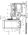
- FIG. 9 illustrates a state in which the carriage 30 is at the home position in the Z-axis direction.
- the color measurement apparatus 1 of the present example is a color measurement apparatus configured to attach the colorimeter 100 that measures the color of the color patch 11 of the color chart 10 in which the color patch 11 and the black frame 12 as a measured portion for grasping the position of the color patch 11 are provided.
- the color measurement apparatus 1 of the present example includes the support base 41 that supports the color chart 10 and the carriage 30 that supports the colorimeter 100.
- the color measurement apparatus 1 of the present example includes the gantry 20, and the gantry 20 includes the carriage motor 22, the carriage belt 23, the front pulley 24, the back pulley 25, or the like, and serves as a scanning mechanism portion that causes the carriage 30 to perform scanning on the support base 41.
- the color measurement apparatus 1 of the present example includes the main substrate 52 or the like as a control portion that controls the colorimeter 100, the carriage 30, and the scanning mechanism portion.
- the carriage 30 has the support portion 310 that supports the colorimeter 100, and the support portion 310 has the hole portion 302a that is an opening portion that exposes the color measurement surface 122 of the colorimeter 100 from the carriage 30 in a state in which the colorimeter 100 is supported.
- the front side sensor 37 and the rear side sensor 38 that measure the black frame 12 as a measured portion and the corner measured portion 13 with the hole portion 302a interposed therebetween are provided in the carriage 30.
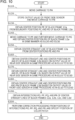
- FIG. 10 is a flowchart illustrating a flow of specifying the position of the color patch 11 by the measurement results of the black frame 12 by the front side sensor 37 and the rear side sensor 38.
- FIG. 11 is a plan view of the color chart 10 and is a view for describing the positions of the front side sensor 37 and the rear side sensor 38 when the black frame 12 is measured by the front side sensor 37 and the rear side sensor 38.
- FIG. 11 is a perspective view of the carriage 30 such that positions of respective components are easy to understand.
- FIG. 12 is a graph illustrating the relationship between the position of the rear side sensor 38 and the output value when a black frame 12a is measured by the rear side sensor 38.
- each step is executed by the control of the main substrate 52 as a control portion.
- the inclination of the color chart 10 illustrated in FIG. 11 with respect to the support base 41 when viewed from the Z-axis direction is specified, and based on the result, the position of the color patch 11 is specified.
- the color chart 10 illustrated in FIG. 11 is a quadrangle, and the black frame 12 that is a linear measured portion as a measured portion along four sides of the color chart 10 in a periphery of an area in which the color patch 11 is provided.
- the storage portion 52a of the color measurement apparatus 1 stores information regarding the positional influence of each of the color patches 11 with respect to the black frame 12a, the black frame 12b, the black frame 12c, and the black frame 12d.
- each of the color patches 11 can be grasped from the position of each of the black frames 12.
- Each of the black frames 12 of the present example is continuously provided along the side of the color chart 10, but, for example, may be discontinuously provided by a dotted line, or further may be configured to be provided in only specific positions along the side.
- a step S110 the carriage motor 22 or the like is driven to move the carriage 30 to a position PA illustrated in FIG. 11 .
- the gantry motor 47 or the like is driven to move the carriage 30 to a position PB illustrated in FIG. 11 .
- the front side sensor 37 is turned on and the output value thereof is recorded.
- the graph in FIG. 12 illustrates an output value of the front side sensor 37 when the carriage 30 is moved from the position PA to the position PB.
- boundary positions PC and PD of the black frame 12a with respect to the fabric portion 14 are obtained from the output value acquired in the step S120. Specifically, the point in time when the output value falls below a predetermined threshold value is set as the boundary position PC, and the point in time when the output value exceeds the threshold value again is set as the boundary position PD. A midpoint between the boundary positions PC and PD is obtained as a center position PE of the black frame 12a.
- a step S140 the carriage motor 22, the gantry motor 47, or the like is driven to move the carriage 30 to a position PF illustrated in FIG. 11 . Then, the gantry motor 47 or the like is further driven to move the carriage 30 to a position PG illustrated in FIG. 11 . Even at this time, the front side sensor 37 is turned on and the output value thereof is recorded. Then, a center position PH of the black frame 12a is obtained from the output value.
- the center position PH is deviated in the Y-axis direction with respect to the center position PE, and the straight line coupling the center position PH and the center position PE is the center straight line of the black frame 12a.
- a step S150 the center straight line of the black frame 12a is obtained.
- a step S160 the center positions PI and PJ of the black frame 12b and the center straight line of the black frame 12b are obtained by the same procedure as in the step S110 to the step S150.
- the rear side sensor 38 is used instead of the front side sensor 37.
- the rear side sensor 38 is provided on the +X direction side of the front side sensor 37. Therefore, by measuring the black frame 12a on the -X direction side by the front side sensor 37 and measuring the black frame 12b on the +X direction side by the rear side sensor 38, the scanning range of the gantry 20 and the carriage 30 in the X-axis direction can be narrowed, and the length of the support base 41 in the X-axis direction can be shortened.
- center positions PK and PL of the black frame 12c and the center straight line of the black frame 12c are obtained by the same procedures as in the step S110 to the step S150.
- the movement direction of the carriage 30 when the black frame 12c is measured is the direction along the Y-axis direction.
- the rear side sensor 38 is used.
- center positions PM and PN of the black frame 12d and the center straight line of the black frame 12d are obtained by the same procedures as in the step S110 to the step S150.
- the movement direction of the carriage 30 when the black frame 12d is measured is also the direction along the Y-axis direction.
- the front side sensor 37 is used.
- the front side sensor 37 is provided on the -Y direction side of the rear side sensor 38. Therefore, by measuring the black frame 12c on the +Y direction side by the rear side sensor 38 and measuring the black frame 12d on the -Y direction side by the front side sensor 37, the scanning range of the carriage 30 in the Y-axis direction can be narrowed, and the length of the support base 41 in the Y-axis direction can be shortened.
- the intersections PO, PP, PQ, and PR are obtained from the center straight line of the black frame 12a, the center straight line of the black frame 12b, the center straight line of the black frame 12c, and the center straight line of the black frame 12d.
- the main substrate 52 can recognize, for example, whether or not the color chart 10 having an originally rectangular shape, due to deformation or the like, is changed into being in a trapezoidal shape, or the like, from the positions of the intersections PO, PP, PQ, and PR.
- a step S200 the main substrate 52 performs correction processing such as trapezoidal correction from the positions of the intersections PO, PP, PQ, and PR, at the same time, specifies the position of the color patch 11, and ends the present flowchart.
- correction processing such as trapezoidal correction from the positions of the intersections PO, PP, PQ, and PR, at the same time, specifies the position of the color patch 11, and ends the present flowchart.
- a color measurement operation can be started for the color patch 11 of which the position is specified by the present flowchart.
- the color measurement apparatus 1 of the present example is provided with the front side sensor 37 and the rear side sensor 38 with the hole portion 302a interposed therebetween, and specifies the position of the color patch 11 based on the measurement results of the front side sensor 37 and the rear side sensor 38 controlled by the main substrate 52.
- a movement distance of the carriage 30 with respect to the black frame 12 can be shortened, and either the front side sensor 37 or the rear side sensor 38 can measure the black frame 12.
- the front side sensor 37 and the rear side sensor 38 are provided with the hole portion 302a interposed in the Y-axis direction, so that when the black frame 12c and the black frame 12d are measured, the movement distance of the carriage 30 can be shortened by at least the length of the hole portion 302a in the Y-axis direction.
- the color measurement apparatus 1 of the present example can grasp the position of the color patch 11 provided on the color chart 10 from the measurement position of the black frame 12 by measuring the black frame 12, and by shortening the movement distance of the carriage 30 in the Y-axis direction, the size of the color measurement apparatus 1 can be suppressed from being increased in the Y-axis direction. Therefore, the color measurement apparatus 1 of the present example has a configuration in which the color patch 11 provided on the color chart 10 can be automatically and easily measured without any positional deviation without an increase in size.
- the color measurement apparatus 1 of the present example can also measure the inclination of the color chart 10 with respect to the support base 41 when viewed from the Z-axis direction
- the color measurement apparatus is configured to attach the colorimeter 100 that measures the color of the color patch 11 of the color chart 10 provided with the black frame 12 to grasp the inclination of the color chart 10 with respect to the support base 41 when viewed from the Z-axis direction, and can also be expressed as a color measurement apparatus that specifies the inclination of the color chart 10 by the measurement results of the front side sensor 37 and the rear side sensor 38.
- the front side sensor 37 and the rear side sensor 38 are provided at positions different from each other not only in the Y-axis direction as the first direction but also in the X-axis direction as the second direction that is the direction intersecting the Y-axis direction. Therefore, as illustrated in FIG. 11 , with respect to the color chart 10 in which the black frame 12 is provided at two different positions in the Y-axis direction and two different positions in the X-axis direction, the movement distance of the carriage 30 can be shortened even in the X-axis direction and even in the Y-axis direction. Therefore, the color measurement apparatus 1 of the present example can particularly effectively suppress a size of the color measurement apparatus 1 from being increased, and at the same time, can perform color measurement on the color patch 11 provided in the color chart 10 without positional deviation.
- the front side sensor 37 and the rear side sensor 38 are provided substantially diagonally with the hole portion 302a as a reference.
- the front side sensor 37 and the rear side sensor 38 may be provided to interpose the hole portion 302a in at least one of the X-axis direction and the Y-axis direction, and may not be provided on a diagonal line.
- the color chart 10 illustrated in FIG. 11 is a quadrangle, and the black frame 12 that is a linear measured portion as a measured portion along four sides of the color chart 10 is provided.
- the color measurement apparatus 1 of the present example can specify the position of the color patch 11 based on the result obtained by measuring the black frame 12 by the front side sensor 37 and the rear side sensor 38, by the control of the main substrate 52.
- the four sides of the color chart 10 can be measured, for example, the intersections PO, PP, PQ, and PR of the four sides of the color chart 10 are calculated, so that the inclination or the like of the color chart 10 with respect to the support base 41 can be accurately grasped, and the position of the color patch 11 can be particularly accurately specified.
- the color chart 10 made of a soft material is easily deformed, and the color chart 10 having a rectangular shape may be changed into being in a trapezoidal shape and be supported by the support base 41.
- the color chart 10 when an attempt is made to specify the position of the color patch 11 assuming that the color chart 10 is rectangular, there is a concern that the color patch 11 deviates from an actual position.
- the color measurement apparatus 1 of the present example based on the result obtained by the front side sensor 37 and the rear side sensor 38 measuring the black frame 12 corresponding to each side of the color chart 10 at at least two points by the control of the main substrate 52, calculates the positions of the center straight lines of the four black frames 12 and the positions of the intersections PO, PP, PQ, and PR among the center straight lines, and specifies the position of the color patch 11 based on the calculated positions of the intersections PO, PP, PQ, and PR.
- the color chart 10 having a rectangular shape is supported by the support base 41 in a state of being deformed into a trapezoidal shape
- the fact that the color chart 10 is changed into being in a trapezoidal shape and is supported by the support base 41 can be grasped based on the measurement results of the front side sensor 37 and the rear side sensor 38, and the position of the color patch 11 can be accurately specified based on the calculated positions of the intersections PO, PP, PQ, and PR.
- the main substrate 52 performs correction processing such as trapezoidal correction from the positions of the intersections PO, PP, PQ, and PR, and at the same time, specifies the position of the color patch 11.
- correction processing such as trapezoidal correction from the positions of the intersections PO, PP, PQ, and PR
- an error may be displayed on the screen portion 105 or the like of the colorimeter 100.
- the deformation of the color chart 10 is large and the position of the color patch 11 is outside the operating area of the carriage 30, or the like, it is preferable to display an error.
- the color chart 10 of FIG. 11 is a quadrangle, and the corner measured portions 13 are provided at the four corners of the color chart 10.
- a corner measured portion 13a, a corner measured portion 13b, and corner measured portion 13c of the corner measured portion 13 are black patches, but a corner measured portion 13d is a white patch.
- the color measurement apparatus 1 of the present example can cause the front side sensor 37 and the rear side sensor 38 to measure at least three of the four corner measured portions 13 by the control of the main substrate 52, and can specify the orientation of the color chart 10 supported by the support base 41 based on the measurement results of the front side sensor 37 and the rear side sensor 38.
- the color chart 10 having a rectangular shape may be supported by the support base 41 in a direction rotated by 180° when viewed from the Z-axis direction that is the support direction of the support base 41.
- the color chart 10 that is a quadrangle and provided with the corner measured portion 13 as a measured portion at at least three corners of the four corners of the color chart 10 by specifying the direction of the color chart 10 supported by the support base 41 based on the results obtained by the front side sensor 37 and the rear side sensor 38 measuring the corner measured portion 13, although the color chart 10 having a rectangular shape is supported by the support base 41 in a direction rotated by 180° when viewed from the Z-axis direction, this can be recognized, and the position of the color patch 11 can be accurately specified.
- an error can be displayed on the screen portion 105 or the like of the colorimeter 100.
- the color chart 10 is not inclined up to the direction rotated by 180° when viewed from the Z-axis direction, when the inclination of the color chart 10 when viewed from the Z-axis direction is large and, for example, the position of the color patch 11 is out of the operation area of the carriage 30, or the like, it is preferable to display an error.
- the color measurement apparatus 1 of the present example measures whether the corner measured portion 13 at the upper left position in FIG. 11 among the corner measured portions 13 is black or white, by the rear side sensor 38.
- the rear side sensor 38 measures whether the corner measured portion 13 at the upper right position in FIG. 11 among the corner measured portions 13 is black or white.
- the front side sensor 37 measures whether the corner measured portion 13 at the lower left position in FIG. 11 is black or white.
- the measurement of the corner measured portion 13 at the lower right position in FIG. 11 may be performed, but may not be performed.
- the front side sensor 37 is used when the corner measured portion 13 at the lower right position in FIG. 11 is measured.
- the color measurement apparatus 1 of the present example can automatically specify the position or the inclination of the color chart 10 on the support base 41, that is, the position of the color patch 11 by executing the control method of the flowchart of FIG. 10 .
- the control method of the flowchart of FIG. 10 is executed by using the color measurement apparatus 1 of the present example, there is a concern that the position of the color patch 11 cannot be automatically specified. For example, when the output value crossing the threshold value illustrated in FIG.
- the color measurement apparatus 1 of the present example cannot automatically specify the position of the color patch 11 although the control method of the flowchart of FIG. 10 is executed.
- the color measurement apparatus 1 of the present example is configured such that a user can manually specify the position of the color patch 11 when the position of the color patch 11 cannot be automatically specified.
- a user can manually specify the position of the color patch 11 when the position of the color patch 11 cannot be automatically specified.
- FIG. 13 an example of a method when the user manually specifies the position of the color patch 11 will be described with reference to FIG. 13 .
- the user when the position of the color patch 11 cannot be automatically specified, or the like, the user holds, for example, a manual adjustment portion 305 or the like illustrated in FIGS. 2 and 3 , and as illustrated in FIG. 13 , the position of the carriage 30 is adjusted to a position PS such that the position of a positioning frame 304 coincides with the position of an upper left patch 11A of the color patch 11 at the upper left in plan view.
- the user acquires the coordinate of the carriage 30 by operating the colorimeter 100 via the operation portion 110 or the like in a state in which the carriage 30 is positioned at the position PS.
- the user adjusts the position of the carriage 30 to a position PT such that the position of the positioning frame 304 coincides with the position of an upper right patch 11B of the color patch 11 at the upper right in plan view, and acquires the coordinate thereof.
- the user adjusts the position of the carriage 30 to a position PU such that the position of the positioning frame 304 coincides with the position of a lower right patch 11C of the color patch 11 at the lower right in plan view, and acquires the coordinate thereof.
- the user adjusts the position of the carriage 30 to a position PV such that the position of the positioning frame 304 coincides with the position of a lower left patch 11D of the color patch 11 at the lower left in plan view, and acquires the coordinate thereof.
- the color measurement apparatus 1 of the present example specifies the position of each of the color patches 11 based on the coordinates of the position PS, the position PT, the position PU, and the position PV.
- the position of each of the color patches 11 is specified based on the coordinates of the four positions of the position PS, the position PT, the position PU, and the position PV, but the position of each of the color patches 11 may be specified based on the coordinates of any three positions of the position PS, the position PT, the position PU, and the position PV.
- the coordinates of the four positions are acquired in the order of the position PS, the position PT, the position PU, and the position PV, in other words, in clockwise order in plan view, but the acquisition order of the coordinates is not particularly limited.
- the error display may be displayed by a computer or the like coupled to the color measurement apparatus 1. Further, at the time of measuring the position PS, the position PT, the position PU, and the position PV, when it is determined that one of these is not at a position within the assumed range, an error may be immediately displayed without waiting for the measurement results of the other positions.
- the display for prompting the manual operation of specifying the position of the color patch 11 again may be performed, or the display for prompting the automatic operation of specifying the position of the color patch 11 illustrated by the control method of the flowchart of FIG. 10 , or the like may be performed.
- the present disclosure is not limited to the above-described examples, and can be realized in various configurations without departing from the gist of the present disclosure.
- the color measurement apparatus 1 of the present example is configured to measure the color of the color measurement target in a state of being in contact with the color measurement target, but may be applied to a configuration in which color measurement is performed on the color measurement target in a state of not being in contact with the color measurement target.
- technical features in the embodiments corresponding to technical features in each form described in a column of the outline of the disclosure can be appropriately replaced or combined to partially or entirely solve the above-described problems, or to partially or entirely achieve the above-described advantageous effects.
- deletion is possible as appropriate.
Landscapes
- Physics & Mathematics (AREA)
- Spectroscopy & Molecular Physics (AREA)
- General Physics & Mathematics (AREA)
- Engineering & Computer Science (AREA)
- Multimedia (AREA)
- Signal Processing (AREA)
- Spectrometry And Color Measurement (AREA)
Abstract
A color measurement apparatus to which a colorimeter that measures a color of a patch of a color measurement target is configured to be attached includes a support base that supports the color measurement target, a carriage that supports the colorimeter, a scanning mechanism portion that causes the carriage to perform scanning on the support base, and a control portion that controls the scanning mechanism portion, in which the carriage includes a support portion that has an opening portion that exposes a color measurement portion from the carriage in a state in which the colorimeter is supported, and a first measurement portion and a second measurement portion that are provided to interpose the opening portion, and the control portion specifies a position of the patch by measurement results of a measured portion by the first measurement portion and the second measurement portion.
Description
- The present application is based on, and claims priority from
JP Application Serial Number 2023-035341, filed March 8, 2023 JP Application Serial Number 2023-089634, filed May 31, 2023 - The present disclosure relates to a color measurement apparatus and a control method.
- In the related art, various color measurement apparatuses that measure a color of a color measurement target are used. Among the above, there is a color measurement apparatus configured to measure a color of a patch of a color measurement target provided with the patch and a measured portion used for grasping a position of the patch, or the like. For example,
JP-A-2000-241248 JP-A-2016-212001 JP-A-2016-212001 - However, in the color measurement apparatus of
JP-A-2000-241248 JP-A-2016-212001 JP-A-2000-241248 - According to an aspect of the present disclosure, there is provided a color measurement apparatus to which a colorimeter that measures a color of a patch of a color measurement target provided with the patch and a measured portion for grasping a position of the patch is configured to be attached, the color measurement apparatus including a support base that supports the color measurement target, a carriage that supports the colorimeter, a scanning mechanism portion that causes the carriage to perform scanning on the support base, and a control portion that controls the scanning mechanism portion, in which the carriage includes a support portion that supports the colorimeter and has an opening portion that exposes a color measurement portion of the colorimeter from the carriage in a state in which the colorimeter is supported by the support portion, and a first measurement portion and a second measurement portion that measure the measured portion and are provided to interpose the opening portion, and the control portion specifies a position of the patch by measurement results of the first measurement portion and the second measurement portion.
- According to another aspect of the present disclosure, there is provided a control method that controls a color measurement apparatus to which a colorimeter that measures a color of a patch of a color measurement target provided with the patch and a measured portion for grasping a position of the patch is configured to be attached, the color measurement apparatus including a support base that supports the color measurement target, a carriage that supports the colorimeter, and a scanning mechanism portion that causes the carriage to perform scanning on the support base, in which the carriage includes a support portion that supports the colorimeter and has an opening portion that exposes a color measurement portion of the colorimeter from the carriage in a state in which the colorimeter is supported by the support portion, and a first measurement portion and a second measurement portion that measure the measured portion and are provided to interpose the opening portion, the control method including specifying a position of the patch by measurement results of the first measurement portion and the second measurement portion.
-
-
FIG. 1 is a schematic perspective view of a colorimeter that can be used in a color measurement apparatus according to an example of the present disclosure. -
FIG. 2 is a perspective view of the color measurement apparatus according to the example of the present disclosure. -
FIG. 3 is a perspective view illustrating an internal configuration of the color measurement apparatus according to the example of the present disclosure. -
FIG. 4 is a bottom view illustrating a periphery of a carriage of the color measurement apparatus according to the example of the present disclosure, and is a view illustrating a state in which the colorimeter ofFIG. 1 is accommodated. -
FIG. 5 is a rear view illustrating a periphery of the carriage of the color measurement apparatus according to the example of the present disclosure, and is a view illustrating a disposition when the colorimeter ofFIG. 1 is accommodated and the carriage is caused to perform scanning. -
FIG. 6 is a rear view illustrating a periphery of the carriage of the color measurement apparatus according to the example of the present disclosure, and is a view illustrating a disposition at a moment at which the colorimeter ofFIG. 1 is accommodated, the carriage is moved downward from the state ofFIG. 5 , and a color measurement portion comes into contact with a color measurement target. -
FIG. 7 is a rear view illustrating a periphery of the carriage of the color measurement apparatus according to the example of the present disclosure, and is a view illustrating a disposition when the colorimeter ofFIG. 1 is accommodated, the carriage is further moved downward from the state ofFIG.6 , and a color of the color measurement target is measured. -
FIG. 8 is a rear view illustrating a periphery of the carriage of the color measurement apparatus according to the example of the present disclosure, and is a view illustrating a disposition when the colorimeter ofFIG. 1 is accommodated, the carriage is further moved downward from the state ofFIG. 7 , and a bottom surface of the carriage comes into contact with the color measurement target. -
FIG. 9 is a rear view illustrating a periphery of the carriage of the color measurement apparatus according to the example of the present disclosure, and is a view illustrating a disposition in a state in which the colorimeter ofFIG. 1 is accommodated and the carriage is moved to a home position. -
FIG. 10 is an example of a control method performed using the color measurement apparatus according to the example of the present disclosure, and is a flowchart illustrating a flow in which a position of a patch is specified by a measurement result of a measured portion by a first measurement portion and a second measurement portion. -
FIG. 11 is a view of the color measurement target, and is a view for describing positions of the first measurement portion and the second measurement portion when a measured portion is measured by the first measurement portion and the second measurement portion. -
FIG. 12 is a graph illustrating a relationship between a position of the first measurement portion and an output value when a measured portion is measured by the first measurement portion. -
FIG. 13 is a view for describing a method of manually specifying a position of a patch when the position of the patch cannot be automatically specified using the color measurement apparatus according to the example of the present disclosure. - Hereinafter, the present disclosure will be schematically described.
- A color measurement apparatus according to a first aspect is a color measurement apparatus to which a colorimeter that measures a color of a patch of a color measurement target provided with the patch and a measured portion for grasping a position of the patch is configured to be attached, the color measurement apparatus including a support base that supports the color measurement target, a carriage that supports the colorimeter, a scanning mechanism portion that causes the carriage to perform scanning on the support base, and a control portion that controls the scanning mechanism portion, in which the carriage includes a support portion that supports the colorimeter and has an opening portion that exposes a color measurement portion of the colorimeter from the carriage in a state in which the colorimeter is supported by the support portion, and a first measurement portion and a second measurement portion that measure the measured portion and are provided to interpose the opening portion, and the control portion specifies a position of the patch by measurement results of the first measurement portion and the second measurement portion.
- According to the present aspect, a position of the patch is specified by measurement results of the first measurement portion and the second measurement portion provided to interpose the opening portion. That is, the measured portion can be measured by one of the first measurement portion and the second measurement portion in which a movement distance of the carriage with respect to the measured portion is shortened. Since the first measurement portion and the second measurement portion are provided to interpose the opening portion, the movement distance of the carriage can be shortened at least by the length of the opening portion. Therefore, by measuring the measured portion, the position of the patch provided on the color measurement target can be grasped from the measurement position of the measured portion, and the size of the color measurement apparatus can be suppressed from being increased by shortening the movement distance of the carriage. Therefore, without increasing the size of the color measurement apparatus, color measurement can be performed on the patch provided on the color measurement target without causing a positional deviation.
- Next, the color measurement apparatus according to a second aspect is an aspect involved in the first aspect, in which the scanning mechanism portion is configured to move the carriage in a first direction and in a second direction intersecting the first direction, and the first measurement portion and the second measurement portion are provided at different positions in any direction of the first direction and the second direction.
- According to the present aspect, the carriage is movable in the first direction and the second direction, and the first measurement portion and the second measurement portion are provided at different positions in any direction of the first direction and the second direction. Therefore, for example, the movement distance of the carriage can be shortened even in the first direction and even in the second direction with respect to the color measurement target in which the measured portions are provided at two different positions in the first direction and two different positions in the second direction. Therefore, by particularly effectively suppressing the size of the color measurement apparatus from being increased, color measurement can be performed on the patch provided on the color measurement target without causing a positional deviation.
- Next, the color measurement apparatus according to a third aspect is an aspect involved in the first or second aspect, in which the color measurement target is a quadrangle and provided with a linear measured portion as the measured portion along four sides of the color measurement target, and the control portion specifies the position of the patch based on results obtained by the first measurement portion and the second measurement portion measuring the linear measured portion.
- According to the present aspect, with respect to the color measurement target that is a quadrangle and provided with the linear measured portion as the measured portion along the four sides, a position of the patch is specified based on results obtained by the first measurement portion and the second measurement portion measuring the linear measured portion. With such a configuration, since the four sides can be measured, for example, by calculating intersections of the four sides, the inclination or the like of the color measurement target with respect to the support base can be accurately grasped, and the position of the patch can be particularly accurately specified.
- Next, the color measurement apparatus according to a fourth aspect is an aspect involved in the third aspect, in which the control portion calculates positions of four straight lines along the linear measured portion and positions of intersections of the straight lines based on results obtained by the first measurement portion and the second measurement portion measuring the linear measured portion corresponding to every side of the color measurement target at at least two points, and specifies the position of the patch based on the calculated position of the intersection.
- For example, the color measurement target made of a soft material is easily deformed, and the color measurement target having a rectangular shape may be changed into a trapezoidal shape and be supported by the support base. In such a case, when an attempt is made to specify the position of the patch assuming that the color measurement target is rectangular, there is a concern that the position of the patch deviates from an actual position. However, according to the present aspect, positions of four straight lines along the linear measured portion and positions of intersections of the straight lines are calculated based on results obtained by the first measurement portion and the second measurement portion measuring the linear measured portion corresponding to every side of the color measurement target at at least two points, and a position of the patch is specified based on the calculated position of the intersection. Therefore, although the color measurement target having a rectangular shape is changed into being in a trapezoidal shape and is supported by the support base, the fact that the color measurement target is changed into being in a trapezoidal shape and is supported by the support base can be grasped based on the measurement results of the first measurement portion and the second measurement portion, and the position of the patch is accurately specified based on the calculated position of the intersection.
- Next, the color measurement apparatus according to a fifth aspect is an aspect involved in any one of the first to fourth aspects, in which the color measurement target is a quadrangle and is provided with a corner measured portion as the measured portion at at least three corners of four corners of the color measurement target, and the control portion specifies an orientation of the color measurement target supported by the support base based on results obtained by the first measurement portion and the second measurement portion measuring the corner measured portion.
- For example, due to a user mistake or the like, the color measurement target having a rectangular shape may be supported by the support base in a direction rotated by 180° when viewed from the support direction of the support base. However, according to the present aspect, with respect to the color measurement target that is a quadrangle and provided with a corner measured portion as the measured portion at at least three corners of four corners of the color measurement target, an orientation of the color measurement target supported by the support base is specified base based on results obtained by the first measurement portion and the second measurement portion measuring the corner measured portion. Therefore, although the color measurement target having a rectangular shape is supported by the support base in a direction rotated by 180° when viewed from the support direction of the support base, this can be recognized, and the position of the patch can be accurately specified.
- Next, the control method according to a sixth aspect is a control method that controls a color measurement apparatus to which a colorimeter that measures a color of a patch of a color measurement target provided with the patch and a measured portion for grasping a position of the patch is configured to be attached, the color measurement apparatus including a support base that supports the color measurement target, a carriage that supports the colorimeter, and a scanning mechanism portion that causes the carriage to perform scanning on the support base, in which the carriage includes a support portion that supports the colorimeter and has an opening portion that exposes a color measurement portion of the colorimeter from the carriage in a state in which the colorimeter is supported by the support portion, and a first measurement portion and a second measurement portion that measure the measured portion and are provided to interpose the opening portion, the control method including specifying a position of the patch by measurement results of the first measurement portion and the second measurement portion.
- According to the present aspect, a position of the patch is specified by measurement results of the first measurement portion and the second measurement portion provided to interpose the opening portion. That is, the measured portion can be measured by one of the first measurement portion and the second measurement portion in which a movement distance of the carriage with respect to the measured portion is shortened. Since the first measurement portion and the second measurement portion are provided to interpose the opening portion, the movement distance of the carriage can be shortened at least by the length of the opening portion. Therefore, by measuring the measured portion, the position of the patch provided on the color measurement target can be grasped from the measurement position of the measured portion, and the size of the color measurement apparatus can be suppressed from being increased by shortening the movement distance of the carriage. Therefore, without increasing the size of the color measurement apparatus, color measurement can be performed on the patch provided on the color measurement target without causing a positional deviation.
- Hereinafter, the present disclosure will be specifically described.
- An X-Y-Z coordinate system illustrated in each drawing is an orthogonal coordinate system, an X-Y plane is a horizontal plane, and an X-Z plane and a Y-Z plane are vertical planes. Here, the Z-axis direction is a vertical direction, that is, a height direction, and a +Z direction is a vertically upward direction and a -Z direction is a vertically downward direction. In addition, the X-axis direction is a horizontal direction orthogonal to the Z-axis direction that is a vertical direction. In addition, the Y-axis direction is a horizontal direction and is a direction orthogonal to both the X-axis direction and the Z-axis direction. In the following description, the +Y direction side of a
color measurement apparatus 1 is referred to as the rear direction side, the - Y direction side of thecolor measurement apparatus 1 is referred to as the front direction side, the +X direction side of thecolor measurement apparatus 1 is referred to as the right direction side, and the -X direction side of thecolor measurement apparatus 1 is referred to as the left direction side. - First, with reference to
FIG. 1 , an example of acolorimeter 100 that can be used in thecolor measurement apparatus 1 according to an example of the present disclosure will be described. Thecolorimeter 100 according to the present example includes acolor measurement port 106, and is an optical device that emits light in the -Z direction from thecolor measurement port 106 and performs color measurement by receiving light reflected by acolor chart 10, which is a color measurement target, as illustrated inFIG. 2 . In other words, the optical axis direction is the Z-axis direction, and the position of the optical axis corresponds to the position of thecolor measurement port 106. - The
colorimeter 100 according to the present example includes acasing 120 having anupper surface 121 that is a surface on the +Z direction side, acolor measurement surface 122 that is a bottom surface on the -Z direction side and is provided with thecolor measurement port 106, arear surface 123 that is a surface on the +Y direction side, afront surface 124 that is a surface on the -Y direction side, aright surface 125 that is a surface on the +X direction side, and aleft surface 126 that is a surface on the -X direction side. - An
operation portion 110 and ascreen portion 105 are disposed on theupper surface 121 in the Y-axis direction. Specifically, theoperation portion 110 is provided on the +Y direction side of theupper surface 121, and thescreen portion 105 is provided on the -Y direction side of theupper surface 121. Theoperation portion 110 includes a plus-shapedbutton 111 configured with abar shape 111a extending in the Y-axis direction and abar shape 111b extending in the X-axis direction, and adetermination button 112 provided at the center of the plus-shapedbutton 111. For example, a user moves the menus to be activated in front/rear and left/right directions by pressing the plus-shapedbutton 111 with respect to a plurality of menus displayed on thescreen portion 105, and can determine the desired menu by pressing thedetermination button 112. - A terminal 101 to which a
USB cable 50 illustrated inFIG. 2 or the like can be coupled is provided on therear surface 123. In addition, thecolorimeter 100 of the present example is provided with aprojection portion 127 and aprojection portion 128 that are projected toward the outside when viewed in the Y-axis direction. Specifically, theprojection portion 127 is provided in an area on the +Z direction side as compared with the center portion of theright surface 125 in the Z-axis direction, and theprojection portion 128 is provided in an area on the +Z direction side as compared with the center portion of theleft surface 126 in the Z-axis direction. - Next, a detailed configuration of the
color measurement apparatus 1 according to the example of the present disclosure will be described with reference toFIGS. 2 to 9 .FIG. 2 illustrates a configuration of thecolor measurement apparatus 1 of the present example. Thecolor measurement apparatus 1 includes amain body portion 40 having asupport base 41 extending in the X-axis direction and the Y-axis direction, and further includes agantry 20 extending in the Y-axis direction to cover a portion of thesupport base 41 from the +Z direction side. - A
carriage 30 having asupport portion 310 that can accommodate thecolorimeter 100 is attached to thegantry 20. Thegantry 20 can move in the X-axis direction with respect to thesupport base 41, and thecarriage 30 can move in the Y-axis direction with respect to thegantry 20. These movements are also referred to as scanning. Here, thecarriage 30 can move in the Y-axis direction with respect to thegantry 20, and can also move in the Z-axis direction with respect to thegantry 20. One end of theUSB cable 50 is coupled to thegantry 20 and the other end of theUSB cable 50 is coupled to thecolorimeter 100 accommodated in thecarriage 30. - The
color chart 10, which is an example of a measurement target, can be placed on thesupport base 41, and thecolor chart 10 is composed by, for example, a plurality ofcolor patches 11, ablack frame 12, a corner measuredportion 13 are provided on afabric portion 14. Thecolor chart 10 is fixed to thesupport base 41 by, for example, attaching an adhesive tape at a periphery of thecolor chart 10, and corresponds to automatic color measurement up to A3 size, for example. However, since thegantry 20 has a gate shape when viewed from the X-axis direction and has aspace portion 21 corresponding to the gate shape, a long paper that exceeds the A3 size can be also placed in the X-axis direction on thesupport base 41. The details of thecolor chart 10 will be described later. - On the -Y direction side of the
main body portion 40, afront surface 42 is provided at a position lower in the -Z direction side than thesupport base 41, and on the +Y direction side of themain body portion 40, arear surface 43 is provided at a position lower in the -Z direction side than thesupport base 41. Apower button 42a that is an example of an operation portion of thecolor measurement apparatus 1 is provided on thefront surface 42. -
FIG. 3 illustrates an internal configuration of thecolor measurement apparatus 1, and is a view in which the exterior component ofFIG. 2 is removed. On the +Z direction side above a case lower 48, thefront frame 44 and therear frame 45 are disposed to extend in the X-axis direction at an interval, and agantry frame 26 having a gate shape and composing a portion of thegantry 20 moves in the X-axis direction along thefront frame 44 and therear frame 45. - The
front frame 44 and therear frame 45 are coupled by acoupling shaft 46 at a position on the +X direction side of themain body portion 40, and the rotational drive of agantry motor 47 is transmitted from thegantry motor 47, which is a power source for moving thegantry 20 in the X-axis direction, to thecoupling shaft 46 via a gear group (not illustrated). By the rotational drive transmitted to thecoupling shaft 46, an endless belt (not illustrated) hung on a pulley (not illustrated) provided on the side of thefront frame 44 that is the -Y direction side of thecoupling shaft 46, and an endless belt (not illustrated) hung on a pulley (not illustrated) provided on the side of therear frame 45 that is the +Y direction side of thecoupling shaft 46 are rotated, and thegantry frame 26 coupled to the endless belts is moved. - A
carriage motor 22 is fixed to the front side corresponding to the -Y direction side of thegantry frame 26, and anendless carriage belt 23 hung on a front pulley 24 and aback pulley 25 rotates via the front pulley 24 coupled to thecarriage motor 22. Acarriage slider 31, which composes a portion of thecarriage 30, is fixed to thecarriage belt 23, and moves along the Y-axis direction in accordance with the pivoting operation of thecarriage belt 23 accompanying the pivoting operation of thecarriage motor 22. Inside themain body portion 40, amain substrate 52, a sub-substrate 53, apower supply box 51, or the like as a control portion are provided. Themain substrate 52 as the control portion is provided with anon-volatile storage portion 52a that can store information. -
FIG. 4 is a bottom view illustrating a periphery of thecarriage 30 in a state in which thecolorimeter 100 is attached to thecarriage 30. Thecolorimeter 100 is supported by thecarriage 30, in which theright surface 125 and theleft surface 126 are supported in the Y-axis direction by arib 301 provided on thecarriage 30, and therear surface 123 and thefront surface 124 are supported in the X-axis direction by arib 303 provided on thecarriage 30. As illustrated inFIG. 4 , afront side sensor 37 and arear side sensor 38 that are configured to measure the width of thecolor chart 10 and the position of thecolor patch 11 by reading the position of theblack frame 12 of thecolor chart 10, are provided on the surface on the -Z direction side of thecarriage 30. Details of thefront side sensor 37 and therear side sensor 38 will be described later. - In the
carriage 30, the power of the Z-axis movementdirection movement motor 36, which is a drive source, is transmitted to themotor gear 61, theworm gear 62, thefirst driving gear 63, and thesecond driving gear 64 in this order, so that thecarriage 30 slidably moves in the Z-axis direction with respect to thegantry 20 via therack gear 65 illustrated inFIG. 5 or the like. In addition, as illustrated inFIG. 4 , thecarriage 30 is provided with ahome position sensor 39 that measures whether or not the position of thecarriage 30 in the Z-axis direction with respect to thegantry 20 is a home position. - Next, mainly with reference to
FIGS. 5 to 9 , the position of thecarriage 30 in the Z-axis direction with respect to thegantry 20, that is, the position of thecarriage 30 and thecolorimeter 100 accommodated in thecarriage 30 in the Z-axis direction with respect to the measurement target placed on thesupport base 41 will be described.FIG. 5 is a view illustrating a disposition when thecarriage 30 performs scanning in a state in which thecolorimeter 100 is accommodated in thecarriage 30, that is, when thecarriage 30 is moved along the Y-axis direction with respect to thegantry 20. At this time, both thecolor measurement surface 122 of thecolorimeter 100 and abottom surface 302 of thecarriage 30 are in a state in which a gap is vacant in the Z-axis direction with respect to thecolor chart 10 that is a measurement target. -
FIG. 6 is a view illustrating a disposition at the moment at which the carriage is moved downward in the -Z direction from the state ofFIG. 5 and thecolor measurement surface 122 of thecolorimeter 100 comes into contact with thecolor chart 10. For example, in the present example, a gap G1 in the Z-axis direction between thebottom surface 302 of thecarriage 30 and thecolor chart 10 at this time is 2 mm. Here, in the present example, thecolorimeter 100 is accommodated in thecarriage 30 in a state in which theprojection portion 127 and theprojection portion 128 are caught and placed by their own weight on therib 301 provided in thecarriage 30, and thecolor measurement surface 122 of thecolorimeter 100 is configured to protrude in the -Z direction from ahole portion 302a provided in thebottom surface 302 of thecarriage 30 illustrated inFIG. 4 . - Therefore, as illustrated in
FIG. 7 , when thecarriage 30 is further moved in the -Z direction from the state ofFIG. 6 , its own weight of thecolorimeter 100 is applied to thecolor measurement surface 122.FIG. 7 illustrates a disposition when the color of the color measurement target is measured, that is, the disposition when the color of thecolor patch 11 and theblack frame 12 of thecolor chart 10 is measured. For example, in the present example, the gap G2 in the Z-axis direction between thebottom surface 302 of thecarriage 30 and thecolor chart 10 at this time is 1 mm. In other words, in thecolor measurement apparatus 1 of the present example, when the color of the color measurement target is measured, thecolor measurement surface 122 is in contact with the color measurement target, but thebottom surface 302 of thecarriage 30 is in a state in which a gap is provided. - In the
color measurement apparatus 1 of the present example, the color measurement is performed in a state in which the entire periphery of thecolor measurement surface 122 of thecolorimeter 100 viewed from the Z-axis direction comes into contact with thecolor chart 10 on thesupport base 41 and follows the surface of thecolor chart 10. With such a configuration, color measurement can be performed in a state in which thecolor measurement port 106 that is an optical axis opening of thecolorimeter 100 is covered with thecolor measurement surface 122, so that it is unlikely affected by external light and color measurement accuracy rises. Even in the state ofFIG. 6 , color measurement can be performed in a state of being unlikely to be affected by external light, but since thecarriage 30, thecolorimeter 100, and thesupport base 41 have a tolerance due to manufacturing variations in parts or the like, the holding position of thecolorimeter 100 of thecarriage 30 or the distance from thecolor measurement surface 122 to thesupport base 41 may deviate. However, by further lowering thecarriage 30 from the state ofFIG. 6 , color measurement can be performed without being affected by such a tolerance. - In addition, in a state of
FIG. 7 , the gap G2 is provided between thebottom surface 302 of thecarriage 30 and thecolor chart 10, and thebottom surface 302 of thecarriage 30 and thecolor chart 10 are in a state of being separated from each other. Therefore, the weight of thecarriage 30 is not transmitted to thecolor chart 10, and it is in a state in which only its own weight of thecolorimeter 100 is applied to thecolor chart 10. Therefore, thecolorimeter 100 is in contact with thecolor chart 10 in a state in which an appropriate load is applied, so that thecolor chart 10 is unlikely to be damaged. - The
color measurement apparatus 1 of the present example can measure color of various color measurement targets. The color measurement target that can be color-measured by thecolor measurement apparatus 1 of the present example has various thicknesses. Therefore, thecolor measurement apparatus 1 of the present example brings thecarriage 30 into contact with the color measurement target by moving thecarriage 30 in the Z-axis direction with respect to the color measurement target to be used, and the abutting height, which is the height of thecarriage 30 at the contact time, can be measured. Describing from another viewpoint, the abutting height of thecarriage 30 is a height of thecarriage 30 when the color measurement target is abutted. Specifically, in thecolor measurement apparatus 1 of the present example, in order to know the abutting height of thecarriage 30, by bringing thebottom surface 302 of thecarriage 30 in contact with the color measurement target and driving the Z-axis movementdirection movement motor 36 to continue lowering the height of thecarriage 30 until a threshold value at which the load of the Z-axis movementdirection movement motor 36 is present is exceeded, the height exceeding the threshold value is measured, so that the abutting height of thecarriage 30 can be known.FIG. 8 is a view illustrating a state when, in order to know the abutting height of thecarriage 30, thebottom surface 302 of thecarriage 30 abuts thecolor chart 10 that is a color measurement target and the threshold value at which the load of the Z-axis movementdirection movement motor 36 is present is exceeded. - In addition, as described above, the
color measurement apparatus 1 of the present example is provided with ahome position sensor 39 that measures whether or not the position of thecarriage 30 in the Z-axis direction with respect to thegantry 20 is a home position.FIG. 9 illustrates a state in which thecarriage 30 is at the home position in the Z-axis direction. - As described above, the
color measurement apparatus 1 of the present example is a color measurement apparatus configured to attach thecolorimeter 100 that measures the color of thecolor patch 11 of thecolor chart 10 in which thecolor patch 11 and theblack frame 12 as a measured portion for grasping the position of thecolor patch 11 are provided. Thecolor measurement apparatus 1 of the present example includes thesupport base 41 that supports thecolor chart 10 and thecarriage 30 that supports thecolorimeter 100. In addition, thecolor measurement apparatus 1 of the present example includes thegantry 20, and thegantry 20 includes thecarriage motor 22, thecarriage belt 23, the front pulley 24, theback pulley 25, or the like, and serves as a scanning mechanism portion that causes thecarriage 30 to perform scanning on thesupport base 41. In addition, thecolor measurement apparatus 1 of the present example includes themain substrate 52 or the like as a control portion that controls thecolorimeter 100, thecarriage 30, and the scanning mechanism portion. - Hereinafter, as an example of a control method performed using the
color measurement apparatus 1 of the present example, a flow of measuring theblack frame 12 as a measured portion by thefront side sensor 37 as a first measurement portion and therear side sensor 38 as a second measurement portion and specifying the position of thecolor patch 11 by the measurement result, will be described. Here, as illustrated inFIG. 4 or the like, thecarriage 30 has thesupport portion 310 that supports thecolorimeter 100, and thesupport portion 310 has thehole portion 302a that is an opening portion that exposes thecolor measurement surface 122 of thecolorimeter 100 from thecarriage 30 in a state in which thecolorimeter 100 is supported. Thefront side sensor 37 and therear side sensor 38 that measure theblack frame 12 as a measured portion and the corner measuredportion 13 with thehole portion 302a interposed therebetween are provided in thecarriage 30. - Further, Hereinafter, the details of the
front side sensor 37 and therear side sensor 38 of thecolor measurement apparatus 1 of the present example and the details of thecolor chart 10 that can be measured by thecolor measurement apparatus 1 of the present example will be described together. Here,FIG. 10 is a flowchart illustrating a flow of specifying the position of thecolor patch 11 by the measurement results of theblack frame 12 by thefront side sensor 37 and therear side sensor 38. In addition,FIG. 11 is a plan view of thecolor chart 10 and is a view for describing the positions of thefront side sensor 37 and therear side sensor 38 when theblack frame 12 is measured by thefront side sensor 37 and therear side sensor 38.FIG. 11 is a perspective view of thecarriage 30 such that positions of respective components are easy to understand.FIG. 12 is a graph illustrating the relationship between the position of therear side sensor 38 and the output value when ablack frame 12a is measured by therear side sensor 38. - In any control method illustrated in the flowchart of
FIG. 10 , each step is executed by the control of themain substrate 52 as a control portion. In addition, in the control method illustrated in the flowchart ofFIG. 10 , the inclination of thecolor chart 10 illustrated inFIG. 11 with respect to thesupport base 41 when viewed from the Z-axis direction is specified, and based on the result, the position of thecolor patch 11 is specified. Thecolor chart 10 illustrated inFIG. 11 is a quadrangle, and theblack frame 12 that is a linear measured portion as a measured portion along four sides of thecolor chart 10 in a periphery of an area in which thecolor patch 11 is provided. Specifically, thecolor chart 10 illustrated inFIG. 11 includes, as theblack frame 12, theblack frame 12a provided in the vicinity of the side of thecolor chart 10 on the -X direction side, ablack frame 12b provided in the vicinity of the side of thecolor chart 10 on the +X direction side, ablack frame 12c provided in the vicinity of the side of thecolor chart 10 on the +Y direction side, and ablack frame 12d provided in the vicinity of the side of thecolor chart 10 on the -Y direction side. Thestorage portion 52a of thecolor measurement apparatus 1 stores information regarding the positional influence of each of thecolor patches 11 with respect to theblack frame 12a, theblack frame 12b, theblack frame 12c, and theblack frame 12d. That is, it is configured such that the position of each of thecolor patches 11 can be grasped from the position of each of the black frames 12. Each of theblack frames 12 of the present example is continuously provided along the side of thecolor chart 10, but, for example, may be discontinuously provided by a dotted line, or further may be configured to be provided in only specific positions along the side. - When the flowchart of
FIG. 10 is started, first, in a step S110, thecarriage motor 22 or the like is driven to move thecarriage 30 to a position PA illustrated inFIG. 11 . Then, in a step S120, thegantry motor 47 or the like is driven to move thecarriage 30 to a position PB illustrated inFIG. 11 . Here, when thecarriage 30 moves from the position PA to the position PB, thefront side sensor 37 is turned on and the output value thereof is recorded. The graph inFIG. 12 illustrates an output value of thefront side sensor 37 when thecarriage 30 is moved from the position PA to the position PB. - Next, in a step S130, boundary positions PC and PD of the
black frame 12a with respect to thefabric portion 14 are obtained from the output value acquired in the step S120. Specifically, the point in time when the output value falls below a predetermined threshold value is set as the boundary position PC, and the point in time when the output value exceeds the threshold value again is set as the boundary position PD. A midpoint between the boundary positions PC and PD is obtained as a center position PE of theblack frame 12a. - Next, in a step S140, the
carriage motor 22, thegantry motor 47, or the like is driven to move thecarriage 30 to a position PF illustrated inFIG. 11 . Then, thegantry motor 47 or the like is further driven to move thecarriage 30 to a position PG illustrated inFIG. 11 . Even at this time, thefront side sensor 37 is turned on and the output value thereof is recorded. Then, a center position PH of theblack frame 12a is obtained from the output value. Here, the center position PH is deviated in the Y-axis direction with respect to the center position PE, and the straight line coupling the center position PH and the center position PE is the center straight line of theblack frame 12a. In a step S150, the center straight line of theblack frame 12a is obtained. - Next, in a step S160, the center positions PI and PJ of the
black frame 12b and the center straight line of theblack frame 12b are obtained by the same procedure as in the step S110 to the step S150. However, in this case, therear side sensor 38 is used instead of thefront side sensor 37. As illustrated inFIG. 11 , therear side sensor 38 is provided on the +X direction side of thefront side sensor 37. Therefore, by measuring theblack frame 12a on the -X direction side by thefront side sensor 37 and measuring theblack frame 12b on the +X direction side by therear side sensor 38, the scanning range of thegantry 20 and thecarriage 30 in the X-axis direction can be narrowed, and the length of thesupport base 41 in the X-axis direction can be shortened. - Next, in a step S170, center positions PK and PL of the
black frame 12c and the center straight line of theblack frame 12c are obtained by the same procedures as in the step S110 to the step S150. However, the movement direction of thecarriage 30 when theblack frame 12c is measured is the direction along the Y-axis direction. In addition, at this time, therear side sensor 38 is used. Next, in a step S180, center positions PM and PN of theblack frame 12d and the center straight line of theblack frame 12d are obtained by the same procedures as in the step S110 to the step S150. The movement direction of thecarriage 30 when theblack frame 12d is measured is also the direction along the Y-axis direction. In addition, at this time, thefront side sensor 37 is used. As illustrated inFIG. 11 , thefront side sensor 37 is provided on the -Y direction side of therear side sensor 38. Therefore, by measuring theblack frame 12c on the +Y direction side by therear side sensor 38 and measuring theblack frame 12d on the -Y direction side by thefront side sensor 37, the scanning range of thecarriage 30 in the Y-axis direction can be narrowed, and the length of thesupport base 41 in the Y-axis direction can be shortened. - Next, in a step S190, the intersections PO, PP, PQ, and PR are obtained from the center straight line of the
black frame 12a, the center straight line of theblack frame 12b, the center straight line of theblack frame 12c, and the center straight line of theblack frame 12d. Here, themain substrate 52 can recognize, for example, whether or not thecolor chart 10 having an originally rectangular shape, due to deformation or the like, is changed into being in a trapezoidal shape, or the like, from the positions of the intersections PO, PP, PQ, and PR. Therefore, in a step S200, themain substrate 52 performs correction processing such as trapezoidal correction from the positions of the intersections PO, PP, PQ, and PR, at the same time, specifies the position of thecolor patch 11, and ends the present flowchart. When the present flowchart is ended, a color measurement operation can be started for thecolor patch 11 of which the position is specified by the present flowchart. - As described above, the
color measurement apparatus 1 of the present example is provided with thefront side sensor 37 and therear side sensor 38 with thehole portion 302a interposed therebetween, and specifies the position of thecolor patch 11 based on the measurement results of thefront side sensor 37 and therear side sensor 38 controlled by themain substrate 52. In this way, by specifying the position of thecolor patch 11 by the measurement results of thefront side sensor 37 and therear side sensor 38 provided with thehole portion 302a interposed therebetween, a movement distance of thecarriage 30 with respect to theblack frame 12 can be shortened, and either thefront side sensor 37 or therear side sensor 38 can measure theblack frame 12. - Specifically, the
front side sensor 37 and therear side sensor 38 are provided with thehole portion 302a interposed in the Y-axis direction, so that when theblack frame 12c and theblack frame 12d are measured, the movement distance of thecarriage 30 can be shortened by at least the length of thehole portion 302a in the Y-axis direction. Thecolor measurement apparatus 1 of the present example can grasp the position of thecolor patch 11 provided on thecolor chart 10 from the measurement position of theblack frame 12 by measuring theblack frame 12, and by shortening the movement distance of thecarriage 30 in the Y-axis direction, the size of thecolor measurement apparatus 1 can be suppressed from being increased in the Y-axis direction. Therefore, thecolor measurement apparatus 1 of the present example has a configuration in which thecolor patch 11 provided on thecolor chart 10 can be automatically and easily measured without any positional deviation without an increase in size. - In addition, since the
color patch 11 can be automatically positioned, the time for the user to manually position thecolor patch 11 can be shortened, and variation in measurement can be suppressed, so that color measurement accuracy can be improved. Since thecolor measurement apparatus 1 of the present example can also measure the inclination of thecolor chart 10 with respect to thesupport base 41 when viewed from the Z-axis direction, the color measurement apparatus is configured to attach thecolorimeter 100 that measures the color of thecolor patch 11 of thecolor chart 10 provided with theblack frame 12 to grasp the inclination of thecolor chart 10 with respect to thesupport base 41 when viewed from the Z-axis direction, and can also be expressed as a color measurement apparatus that specifies the inclination of thecolor chart 10 by the measurement results of thefront side sensor 37 and therear side sensor 38. - In addition, as described above, the
front side sensor 37 and therear side sensor 38 are provided at positions different from each other not only in the Y-axis direction as the first direction but also in the X-axis direction as the second direction that is the direction intersecting the Y-axis direction. Therefore, as illustrated inFIG. 11 , with respect to thecolor chart 10 in which theblack frame 12 is provided at two different positions in the Y-axis direction and two different positions in the X-axis direction, the movement distance of thecarriage 30 can be shortened even in the X-axis direction and even in the Y-axis direction. Therefore, thecolor measurement apparatus 1 of the present example can particularly effectively suppress a size of thecolor measurement apparatus 1 from being increased, and at the same time, can perform color measurement on thecolor patch 11 provided in thecolor chart 10 without positional deviation. - Here, as illustrated in
FIG. 4 andFIG. 11 , in thecolor measurement apparatus 1 of the present example, thefront side sensor 37 and therear side sensor 38 are provided substantially diagonally with thehole portion 302a as a reference. However, the present disclosure is not limited to this configuration. Thefront side sensor 37 and therear side sensor 38 may be provided to interpose thehole portion 302a in at least one of the X-axis direction and the Y-axis direction, and may not be provided on a diagonal line. - In addition, the
color chart 10 illustrated inFIG. 11 is a quadrangle, and theblack frame 12 that is a linear measured portion as a measured portion along four sides of thecolor chart 10 is provided. As described above, thecolor measurement apparatus 1 of the present example can specify the position of thecolor patch 11 based on the result obtained by measuring theblack frame 12 by thefront side sensor 37 and therear side sensor 38, by the control of themain substrate 52. With such a configuration, since the four sides of thecolor chart 10 can be measured, for example, the intersections PO, PP, PQ, and PR of the four sides of thecolor chart 10 are calculated, so that the inclination or the like of thecolor chart 10 with respect to thesupport base 41 can be accurately grasped, and the position of thecolor patch 11 can be particularly accurately specified. - In addition, for example, the
color chart 10 made of a soft material is easily deformed, and thecolor chart 10 having a rectangular shape may be changed into being in a trapezoidal shape and be supported by thesupport base 41. In such a case, when an attempt is made to specify the position of thecolor patch 11 assuming that thecolor chart 10 is rectangular, there is a concern that thecolor patch 11 deviates from an actual position. However, thecolor measurement apparatus 1 of the present example, based on the result obtained by thefront side sensor 37 and therear side sensor 38 measuring theblack frame 12 corresponding to each side of thecolor chart 10 at at least two points by the control of themain substrate 52, calculates the positions of the center straight lines of the fourblack frames 12 and the positions of the intersections PO, PP, PQ, and PR among the center straight lines, and specifies the position of thecolor patch 11 based on the calculated positions of the intersections PO, PP, PQ, and PR. Therefore, although thecolor chart 10 having a rectangular shape is supported by thesupport base 41 in a state of being deformed into a trapezoidal shape, the fact that thecolor chart 10 is changed into being in a trapezoidal shape and is supported by thesupport base 41 can be grasped based on the measurement results of thefront side sensor 37 and therear side sensor 38, and the position of thecolor patch 11 can be accurately specified based on the calculated positions of the intersections PO, PP, PQ, and PR. - In the control method of the flowchart of
FIG. 10 , in the step S200, themain substrate 52 performs correction processing such as trapezoidal correction from the positions of the intersections PO, PP, PQ, and PR, and at the same time, specifies the position of thecolor patch 11. However, when it is measured that thecolor chart 10 having a rectangular shape is in a trapezoidal shape and is supported by thesupport base 41, an error may be displayed on thescreen portion 105 or the like of thecolorimeter 100. Particularly, for example, when the deformation of thecolor chart 10 is large and the position of thecolor patch 11 is outside the operating area of thecarriage 30, or the like, it is preferable to display an error. - In addition, as illustrated in
FIG. 11 , thecolor chart 10 ofFIG. 11 is a quadrangle, and the corner measuredportions 13 are provided at the four corners of thecolor chart 10. A corner measuredportion 13a, a corner measuredportion 13b, and corner measuredportion 13c of the corner measuredportion 13 are black patches, but a corner measuredportion 13d is a white patch. Then, thecolor measurement apparatus 1 of the present example can cause thefront side sensor 37 and therear side sensor 38 to measure at least three of the four corner measuredportions 13 by the control of themain substrate 52, and can specify the orientation of thecolor chart 10 supported by thesupport base 41 based on the measurement results of thefront side sensor 37 and therear side sensor 38. - For example, due to a user's mistake or the like, the
color chart 10 having a rectangular shape may be supported by thesupport base 41 in a direction rotated by 180° when viewed from the Z-axis direction that is the support direction of thesupport base 41. However, with respect to thecolor chart 10 that is a quadrangle and provided with the corner measuredportion 13 as a measured portion at at least three corners of the four corners of thecolor chart 10, by specifying the direction of thecolor chart 10 supported by thesupport base 41 based on the results obtained by thefront side sensor 37 and therear side sensor 38 measuring the corner measuredportion 13, although thecolor chart 10 having a rectangular shape is supported by thesupport base 41 in a direction rotated by 180° when viewed from the Z-axis direction, this can be recognized, and the position of thecolor patch 11 can be accurately specified. In addition, in such a case, an error can be displayed on thescreen portion 105 or the like of thecolorimeter 100. Although thecolor chart 10 is not inclined up to the direction rotated by 180° when viewed from the Z-axis direction, when the inclination of thecolor chart 10 when viewed from the Z-axis direction is large and, for example, the position of thecolor patch 11 is out of the operation area of thecarriage 30, or the like, it is preferable to display an error. - Specifically, the
color measurement apparatus 1 of the present example measures whether the corner measuredportion 13 at the upper left position inFIG. 11 among the corner measuredportions 13 is black or white, by therear side sensor 38. Next, therear side sensor 38 measures whether the corner measuredportion 13 at the upper right position inFIG. 11 among the corner measuredportions 13 is black or white. Then, thefront side sensor 37 measures whether the corner measuredportion 13 at the lower left position inFIG. 11 is black or white. In addition, the measurement of the corner measuredportion 13 at the lower right position inFIG. 11 may be performed, but may not be performed. Thefront side sensor 37 is used when the corner measuredportion 13 at the lower right position inFIG. 11 is measured. - When all of the corner measured
portions 13 at the positions of the three corner portions of the upper left, the upper right, and the lower left inFIG. 11 are black, it is determined that thecolor chart 10 is disposed on thesupport base 41 in a normal orientation. On the other hand, when thecolor chart 10 is disposed on thesupport base 41 in an orientation rotated by 180° when viewed from the Z-axis direction, since the corner measuredportion 13d is disposed at the corner portion at the upper left position inFIG. 11 , the measurement result of the corner measuredportion 13 at this position by therear side sensor 38 is white, and themain substrate 52 recognizes that thecolor chart 10 is supported by thesupport base 41 in a direction rotated by 180° when viewed from the Z-axis direction. - As described above, the
color measurement apparatus 1 of the present example can automatically specify the position or the inclination of thecolor chart 10 on thesupport base 41, that is, the position of thecolor patch 11 by executing the control method of the flowchart ofFIG. 10 . On the other hand, although the control method of the flowchart ofFIG. 10 is executed by using thecolor measurement apparatus 1 of the present example, there is a concern that the position of thecolor patch 11 cannot be automatically specified. For example, when the output value crossing the threshold value illustrated inFIG. 12 is not obtained due to the usage environment or the like of thecolor measurement apparatus 1 when theblack frame 12 is measured by thefront side sensor 37 or therear side sensor 38, or when the inclination of thecolor chart 10 on thesupport base 41 is excessively large, thecolor measurement apparatus 1 of the present example cannot automatically specify the position of thecolor patch 11 although the control method of the flowchart ofFIG. 10 is executed. - Therefore, the
color measurement apparatus 1 of the present example is configured such that a user can manually specify the position of thecolor patch 11 when the position of thecolor patch 11 cannot be automatically specified. Hereinafter, an example of a method when the user manually specifies the position of thecolor patch 11 will be described with reference toFIG. 13 . - In the
color measurement apparatus 1 of the present example, when the position of thecolor patch 11 cannot be automatically specified, or the like, the user holds, for example, amanual adjustment portion 305 or the like illustrated inFIGS. 2 and3 , and as illustrated inFIG. 13 , the position of thecarriage 30 is adjusted to a position PS such that the position of apositioning frame 304 coincides with the position of an upperleft patch 11A of thecolor patch 11 at the upper left in plan view. Next, the user acquires the coordinate of thecarriage 30 by operating thecolorimeter 100 via theoperation portion 110 or the like in a state in which thecarriage 30 is positioned at the position PS. - Next, the user adjusts the position of the
carriage 30 to a position PT such that the position of thepositioning frame 304 coincides with the position of an upperright patch 11B of thecolor patch 11 at the upper right in plan view, and acquires the coordinate thereof. Next, the user adjusts the position of thecarriage 30 to a position PU such that the position of thepositioning frame 304 coincides with the position of a lowerright patch 11C of thecolor patch 11 at the lower right in plan view, and acquires the coordinate thereof. Further, the user adjusts the position of thecarriage 30 to a position PV such that the position of thepositioning frame 304 coincides with the position of a lowerleft patch 11D of thecolor patch 11 at the lower left in plan view, and acquires the coordinate thereof. - Then, the
color measurement apparatus 1 of the present example specifies the position of each of thecolor patches 11 based on the coordinates of the position PS, the position PT, the position PU, and the position PV. In the above description, the position of each of thecolor patches 11 is specified based on the coordinates of the four positions of the position PS, the position PT, the position PU, and the position PV, but the position of each of thecolor patches 11 may be specified based on the coordinates of any three positions of the position PS, the position PT, the position PU, and the position PV. In addition, in the above description, the coordinates of the four positions are acquired in the order of the position PS, the position PT, the position PU, and the position PV, in other words, in clockwise order in plan view, but the acquisition order of the coordinates is not particularly limited. - In addition, in manually specifying the position of the
color patch 11 as described above, when at least one of the position PS, the position PT, the position PU, and the position PV is not at a position within the assumed range, the error display may be displayed by a computer or the like coupled to thecolor measurement apparatus 1. Further, at the time of measuring the position PS, the position PT, the position PU, and the position PV, when it is determined that one of these is not at a position within the assumed range, an error may be immediately displayed without waiting for the measurement results of the other positions. After the error display, the display for prompting the manual operation of specifying the position of thecolor patch 11 again may be performed, or the display for prompting the automatic operation of specifying the position of thecolor patch 11 illustrated by the control method of the flowchart ofFIG. 10 , or the like may be performed. - The present disclosure is not limited to the above-described examples, and can be realized in various configurations without departing from the gist of the present disclosure. For example, the
color measurement apparatus 1 of the present example is configured to measure the color of the color measurement target in a state of being in contact with the color measurement target, but may be applied to a configuration in which color measurement is performed on the color measurement target in a state of not being in contact with the color measurement target. In addition, for example, technical features in the embodiments corresponding to technical features in each form described in a column of the outline of the disclosure can be appropriately replaced or combined to partially or entirely solve the above-described problems, or to partially or entirely achieve the above-described advantageous effects. In addition, unless the technical features are described as essential in the present specification, deletion is possible as appropriate.
Claims (6)
- A color measurement apparatus to which a colorimeter that measures a color of a patch of a color measurement target provided with the patch and a measured portion for grasping a position of the patch is configured to be attached, the color measurement apparatus comprising:a support base that supports the color measurement target;a carriage that supports the colorimeter;a scanning mechanism portion that causes the carriage to perform scanning on the support base; anda control portion that controls the scanning mechanism portion, whereinthe carriage includesa support portion that supports the colorimeter and has an opening portion that exposes a color measurement portion of the colorimeter from the carriage in a state in which the colorimeter is supported by the support portion, anda first measurement portion and a second measurement portion that measure the measured portion and are provided to interpose the opening portion, andthe control portion specifies a position of the patch by measurement results of the first measurement portion and the second measurement portion.
- The color measurement apparatus according to claim 1, whereinthe scanning mechanism portion is configured to move the carriage in a first direction and in a second direction intersecting the first direction, andthe first measurement portion and the second measurement portion are provided at different positions in any direction of the first direction and the second direction.
- The color measurement apparatus according to claim 1 or 2, whereinthe color measurement target is a quadrangle and provided with a linear measured portion as the measured portion along four sides of the color measurement target, andthe control portion specifies the position of the patch based on results obtained by the first measurement portion and the second measurement portion measuring the linear measured portion.
- The color measurement apparatus according to claim 3, whereinthe control portioncalculates positions of four straight lines along the linear measured portion and positions of intersections of the straight lines based on results obtained by the first measurement portion and the second measurement portion measuring the linear measured portion corresponding to every side of the color measurement target at at least two points, andspecifies the position of the patch based on the calculated position of the intersection.
- The color measurement apparatus according to claim 1 or 2, whereinthe color measurement target is a quadrangle and is provided with a corner measured portion as the measured portion at at least three corners of four corners of the color measurement target, andthe control portion specifies an orientation of the color measurement target supported by the support base based on results obtained by the first measurement portion and the second measurement portion measuring the corner measured portion.
- A control method that controls a color measurement apparatus to which a colorimeter that measures a color of a patch of a color measurement target provided with the patch and a measured portion for grasping a position of the patch is configured to be attached, the color measurement apparatus includinga support base that supports the color measurement target,a carriage that supports the colorimeter, anda scanning mechanism portion that causes the carriage to perform scanning on the support base, in whichthe carriage includesa support portion that supports the colorimeter and has an opening portion that exposes a color measurement portion of the colorimeter from the carriage in a state in which the colorimeter is supported by the support portion, anda first measurement portion and a second measurement portion that measure the measured portion and are provided to interpose the opening portion, the control method comprising:
specifying a position of the patch by measurement results of the first measurement portion and the second measurement portion.
Applications Claiming Priority (2)
| Application Number | Priority Date | Filing Date | Title |
|---|---|---|---|
| JP2023035341 | 2023-03-08 | ||
| JP2023089634A JP2024127690A (en) | 2023-03-08 | 2023-05-31 | Color measurement device and control method |
Publications (1)
| Publication Number | Publication Date |
|---|---|
| EP4428506A1 true EP4428506A1 (en) | 2024-09-11 |
Family
ID=90362769
Family Applications (1)
| Application Number | Title | Priority Date | Filing Date |
|---|---|---|---|
| EP24161876.8A Pending EP4428506A1 (en) | 2023-03-08 | 2024-03-06 | Color measurement apparatus and control method |
Country Status (2)
| Country | Link |
|---|---|
| US (1) | US20240302209A1 (en) |
| EP (1) | EP4428506A1 (en) |
Citations (5)
| Publication number | Priority date | Publication date | Assignee | Title |
|---|---|---|---|---|
| JP2000241248A (en) | 1999-02-17 | 2000-09-08 | Fuji Photo Film Co Ltd | Colorimetric instrument |
| JP2000253262A (en) * | 1999-02-25 | 2000-09-14 | Sharp Corp | Color information measurement system |
| JP2016212001A (en) | 2015-05-11 | 2016-12-15 | サカタインクスエンジニアリング株式会社 | Colorimetric method and automatic colorimetric device |
| JP2023035341A (en) | 2021-09-01 | 2023-03-13 | 浜松ホトニクス株式会社 | Laser amplifier device and laser amplification method |
| JP2023089634A (en) | 2021-12-16 | 2023-06-28 | 日東電工株式会社 | How to cut the sheet material |
-
2024
- 2024-03-06 EP EP24161876.8A patent/EP4428506A1/en active Pending
- 2024-03-07 US US18/598,725 patent/US20240302209A1/en active Pending
Patent Citations (5)
| Publication number | Priority date | Publication date | Assignee | Title |
|---|---|---|---|---|
| JP2000241248A (en) | 1999-02-17 | 2000-09-08 | Fuji Photo Film Co Ltd | Colorimetric instrument |
| JP2000253262A (en) * | 1999-02-25 | 2000-09-14 | Sharp Corp | Color information measurement system |
| JP2016212001A (en) | 2015-05-11 | 2016-12-15 | サカタインクスエンジニアリング株式会社 | Colorimetric method and automatic colorimetric device |
| JP2023035341A (en) | 2021-09-01 | 2023-03-13 | 浜松ホトニクス株式会社 | Laser amplifier device and laser amplification method |
| JP2023089634A (en) | 2021-12-16 | 2023-06-28 | 日東電工株式会社 | How to cut the sheet material |
Also Published As
| Publication number | Publication date |
|---|---|
| US20240302209A1 (en) | 2024-09-12 |
Similar Documents
| Publication | Publication Date | Title |
|---|---|---|
| KR100619471B1 (en) | Bonding apparatus | |
| JP2001136000A (en) | Jig for detecting attaching accuracy of attaching apparatus and method for detecting attaching accuracy | |
| US10412869B2 (en) | Component mounting device and component mounting method | |
| EP1231828A1 (en) | Device and method for mounting parts | |
| US20190133010A1 (en) | Contactless electric power supply device | |
| TW200928374A (en) | Circit board inspection device | |
| CN110220483A (en) | Three axial plane degree detection systems of one kind and its detection method | |
| KR100311749B1 (en) | Module head zero point adjusting device of surface mounting device and a zero point adjusting method thereof | |
| JP2003298294A (en) | Electronic circuit component mounting system | |
| US20240302209A1 (en) | Color measurement apparatus and control method | |
| US20240302215A1 (en) | Control method and color measurement apparatus | |
| EP3328178B1 (en) | Component mounting machine | |
| KR20100052816A (en) | Dispensing apparatus having dual dispenser for manufacturing camera module and dispensing method using the same | |
| US20240353263A1 (en) | Colorimetric apparatus and adjustment method | |
| JP2024014297A (en) | Component mounting equipment | |
| JP2024127690A (en) | Color measurement device and control method | |
| KR101266714B1 (en) | Componemt mounting method of component placement apparatus and component placement apparatus | |
| JP2004128384A (en) | Component mounting device and component mounting method | |
| JP2024164437A (en) | Color measurement device and color measurement method | |
| CN118624027A (en) | Colorimetric device and control method | |
| US12607505B2 (en) | Color measurement apparatus | |
| US20240302211A1 (en) | Color measurement apparatus | |
| US20240377313A1 (en) | Colorimetric apparatus and colorimetric method | |
| JPS61500341A (en) | Method and apparatus for positioning elements relative to a workpiece | |
| CN211824966U (en) | Calibration equipment |
Legal Events
| Date | Code | Title | Description |
|---|---|---|---|
| PUAI | Public reference made under article 153(3) epc to a published international application that has entered the european phase |
Free format text: ORIGINAL CODE: 0009012 |
|
| STAA | Information on the status of an ep patent application or granted ep patent |
Free format text: STATUS: THE APPLICATION HAS BEEN PUBLISHED |
|
| AK | Designated contracting states |
Kind code of ref document: A1 Designated state(s): AL AT BE BG CH CY CZ DE DK EE ES FI FR GB GR HR HU IE IS IT LI LT LU LV MC ME MK MT NL NO PL PT RO RS SE SI SK SM TR |
|
| STAA | Information on the status of an ep patent application or granted ep patent |
Free format text: STATUS: REQUEST FOR EXAMINATION WAS MADE |
|
| 17P | Request for examination filed |
Effective date: 20241224 |