EP4428478A1 - Heat exchanger with crossing heat exchange tubes - Google Patents
Heat exchanger with crossing heat exchange tubes Download PDFInfo
- Publication number
- EP4428478A1 EP4428478A1 EP24162445.1A EP24162445A EP4428478A1 EP 4428478 A1 EP4428478 A1 EP 4428478A1 EP 24162445 A EP24162445 A EP 24162445A EP 4428478 A1 EP4428478 A1 EP 4428478A1
- Authority
- EP
- European Patent Office
- Prior art keywords
- tube
- manifold
- tubes
- manifold wall
- flowpath
- Prior art date
- Legal status (The legal status is an assumption and is not a legal conclusion. Google has not performed a legal analysis and makes no representation as to the accuracy of the status listed.)
- Granted
Links
Images






Classifications
-
- F—MECHANICAL ENGINEERING; LIGHTING; HEATING; WEAPONS; BLASTING
- F28—HEAT EXCHANGE IN GENERAL
- F28D—HEAT-EXCHANGE APPARATUS, NOT PROVIDED FOR IN ANOTHER SUBCLASS, IN WHICH THE HEAT-EXCHANGE MEDIA DO NOT COME INTO DIRECT CONTACT
- F28D7/00—Heat-exchange apparatus having stationary tubular conduit assemblies for both heat-exchange media, the media being in contact with different sides of a conduit wall
- F28D7/16—Heat-exchange apparatus having stationary tubular conduit assemblies for both heat-exchange media, the media being in contact with different sides of a conduit wall the conduits being arranged in parallel spaced relation
- F28D7/1615—Heat-exchange apparatus having stationary tubular conduit assemblies for both heat-exchange media, the media being in contact with different sides of a conduit wall the conduits being arranged in parallel spaced relation the conduits being inside a casing and extending at an angle to the longitudinal axis of the casing; the conduits crossing the conduit for the other heat exchange medium
-
- F—MECHANICAL ENGINEERING; LIGHTING; HEATING; WEAPONS; BLASTING
- F28—HEAT EXCHANGE IN GENERAL
- F28D—HEAT-EXCHANGE APPARATUS, NOT PROVIDED FOR IN ANOTHER SUBCLASS, IN WHICH THE HEAT-EXCHANGE MEDIA DO NOT COME INTO DIRECT CONTACT
- F28D7/00—Heat-exchange apparatus having stationary tubular conduit assemblies for both heat-exchange media, the media being in contact with different sides of a conduit wall
- F28D7/0058—Heat-exchange apparatus having stationary tubular conduit assemblies for both heat-exchange media, the media being in contact with different sides of a conduit wall the conduits for only one medium being tubes having different orientations to each other or crossing the conduit for the other heat exchange medium
-
- F—MECHANICAL ENGINEERING; LIGHTING; HEATING; WEAPONS; BLASTING
- F28—HEAT EXCHANGE IN GENERAL
- F28F—DETAILS OF HEAT-EXCHANGE AND HEAT-TRANSFER APPARATUS, OF GENERAL APPLICATION
- F28F9/00—Casings; Header boxes; Auxiliary supports for elements; Auxiliary members within casings
- F28F9/02—Header boxes; End plates
-
- F—MECHANICAL ENGINEERING; LIGHTING; HEATING; WEAPONS; BLASTING
- F28—HEAT EXCHANGE IN GENERAL
- F28D—HEAT-EXCHANGE APPARATUS, NOT PROVIDED FOR IN ANOTHER SUBCLASS, IN WHICH THE HEAT-EXCHANGE MEDIA DO NOT COME INTO DIRECT CONTACT
- F28D21/00—Heat-exchange apparatus not covered by any of the groups F28D1/00 - F28D20/00
- F28D2021/0019—Other heat exchangers for particular applications; Heat exchange systems not otherwise provided for
- F28D2021/0026—Other heat exchangers for particular applications; Heat exchange systems not otherwise provided for for combustion engines, e.g. for gas turbines or for Stirling engines
-
- F—MECHANICAL ENGINEERING; LIGHTING; HEATING; WEAPONS; BLASTING
- F28—HEAT EXCHANGE IN GENERAL
- F28F—DETAILS OF HEAT-EXCHANGE AND HEAT-TRANSFER APPARATUS, OF GENERAL APPLICATION
- F28F2225/00—Reinforcing means
- F28F2225/04—Reinforcing means for conduits
-
- F—MECHANICAL ENGINEERING; LIGHTING; HEATING; WEAPONS; BLASTING
- F28—HEAT EXCHANGE IN GENERAL
- F28F—DETAILS OF HEAT-EXCHANGE AND HEAT-TRANSFER APPARATUS, OF GENERAL APPLICATION
- F28F9/00—Casings; Header boxes; Auxiliary supports for elements; Auxiliary members within casings
- F28F9/007—Auxiliary supports for elements
- F28F9/013—Auxiliary supports for elements for tubes or tube-assemblies
Definitions
- This disclosure relates generally to a heat exchange system and, more particularly, to a heat exchanger with multiple heat exchange tubes crossing a flowpath.
- a heat exchanger that includes a duct and a plurality of tubes.
- the duct includes a flowpath, a first sidewall, a second sidewall, a first manifold wall and a second manifold wall.
- the flowpath extends longitudinally through the duct.
- the flowpath extends laterally within the duct between the first sidewall and the second sidewall.
- the flowpath extends vertically within the duct between the first manifold wall and the second manifold wall.
- the first manifold wall is configured to form a peripheral boundary of a first manifold plenum outside of the duct.
- the second manifold wall is configured to form a peripheral boundary of a second manifold plenum outside of the duct.
- the tubes extend vertically across the flowpath and are connected to the first manifold wall and the second manifold wall. Each of the tubes has a bore configured to fluidly couple the first manifold plenum to the second manifold plenum.
- the tubes include a first tube and a second tube. The first tube is adjacent and angularly offset from the second tube.
- another heat exchanger includes a first manifold, a second manifold and a plurality of tubes.
- the first manifold includes a first manifold wall and a first manifold plenum.
- the first manifold wall is between and partially forms the first manifold plenum and a flowpath.
- the second manifold includes a second manifold wall and a second manifold plenum.
- the second manifold wall is between and partially forms the second manifold plenum and the flowpath.
- the tubes extend vertically across the flowpath and are connected to the first manifold wall and the second manifold wall.
- Each of the tubes has an internal passage fluidly coupling the first manifold plenum to the second manifold plenum.
- the tubes include a first tube and a second tube that is angularly offset from the first tube within the flowpath.
- the first tube extends along a straight first trajectory out from the first manifold wall, through the flowpath and to the second manifold wall.
- the second tube extends along a straight second trajectory out from the first manifold wall, through the flowpath and to the second manifold wall.
- another heat exchanger includes a first manifold, a second manifold and a plurality of tubes.
- the first manifold includes a first manifold wall and a first manifold plenum.
- the first manifold wall is between and partially forms the first manifold plenum and a flowpath.
- the second manifold includes a second manifold wall and a second manifold plenum.
- the second manifold wall is between and partially forms the second manifold plenum and the flowpath.
- the tubes extend vertically across the flowpath and are connected to the first manifold wall and the second manifold wall.
- Each of the tubes has an internal passage fluidly coupling the first manifold plenum to the second manifold plenum.
- the tubes include a first tube and a second tube.
- the first tube is angularly offset from the second tube at a first location vertically between the first manifold wall and the second manifold wall.
- the first tube is attached to the second tube at the first location.
- the internal passage of the first tube is fluidly uncoupled from the internal passage of the second tube vertically between the first manifold wall and the second manifold wall.
- the first tube may extend along a straight first trajectory out from the first manifold wall, through the flowpath and to the second manifold wall.
- the second tube may extend along a straight second trajectory out from the first manifold wall, through the flowpath and to the second manifold wall.
- the first tube may extend along the straight first trajectory through the first manifold wall and/or the second manifold wall.
- the second tube may extend along the straight second trajectory through the first manifold wall and/or the second manifold wall.
- the first tube may be angularly offset from the first manifold wall and/or the second manifold wall by a first acute angle.
- the second tube may be angularly offset from the first manifold wall and/or the second manifold wall by a second acute angle.
- the heat exchanger may also include a heat exchanger housing including the first manifold wall and the second manifold wall.
- the flowpath may extend longitudinally through the heat exchanger housing.
- At least one of the tubes may be configured according to a heat exchange tube crossover parameter between 0.75 inches/crossover (1.9 cm/crossover) and 4.0 inches/crossover (10 cm/crossover).
- the first tube may be laterally adjacent the second tube.
- the first tube may engage the second tube.
- the first tube may be connected to the second tube at a first location within the flowpath vertically between the first manifold wall and the second manifold wall.
- the tubes may also include a third tube.
- the first tube may be adjacent and angularly offset from the third tube.
- the first tube may be connected to the third tube at a second location within the flowpath vertically between the first location and the second manifold wall.
- a connection between the first tube and the second tube at the first location may be a rigid connection.
- a connection between the first tube and the second tube at the first location may be a compliant connection.
- the bore of the first tube may be fluidly discrete from the bore of the second tube within the flowpath.
- the first tube may be angularly offset from the second tube by a first acute angle.
- the first tube may be angularly offset from the first manifold wall by a second acute angle.
- the second acute angle may be greater than the first acute angle.
- the first tube may also be angularly offset from the second manifold wall by the second acute angle.
- the first tube may extend along a straight first trajectory out of a first aperture in the first manifold wall, through the flowpath and into a first aperture in the second manifold wall.
- the second tube may extend along a straight second trajectory out of a second aperture in the first manifold wall, through the flowpath and into a second aperture in the second manifold wall.
- the tubes may be arranged into a plurality of first arrays and a plurality of second arrays that are laterally interposed with the first arrays.
- the tubes arranged in the first arrays may be parallel with one another.
- the tubes arranged in the second arrays may be parallel with one another.
- One of the first arrays may include the first tube.
- One of the second arrays may include the second tube.
- the duct may be configured as part of a monolithic body.
- the present disclosure may include any one or more of the individual features disclosed above and/or below alone or in any combination thereof.
- FIGS. 1 and 2 illustrate a heat exchanger 20 (e.g., a microtube heat exchanger) for a heat exchange system 22.
- the heat exchange system 22 may be a cooling system or a heating system for a gas turbine engine. The present disclosure, however, is not limited to turbine engine applications.
- the heat exchanger 20 of FIG. 1 and 2 includes a heat exchanger (HX) housing 24 and a plurality of heat exchange (HX) tubes 26A and 26B (generally referred to as "26").
- the HX housing 24 of FIG. 1 extends laterally (e.g., along an x-axis) between and to opposing lateral sides 28 and 30 of the heat exchanger 20 and its HX housing 24.
- the HX housing 24 extends vertically (e.g., along a y-axis) between and to opposing vertical sides 32 and 34 of the heat exchanger 20 and its HX housing 24.
- vertical is used herein to describe a depthwise direction and is not limited to a gravitational up/down direction.
- the HX housing 24 of FIG. 2 extends longitudinally (e.g., along a z-axis) between and to opposing longitudinal ends 36 and 38 of the heat exchanger 20 and its HX housing 24.
- the HX housing 24 of FIGS. 1 and 2 includes a heat exchanger (HX) duct 40, a first manifold 42 and a second manifold 44.
- HX heat exchanger
- the HX duct 40 includes a duct first sidewall 46, a duct second sidewall 47, a duct first manifold wall 48 and a duct second manifold wall 49. These duct walls 46-49 are arranged together to provide the HX duct 40 with an internal duct flowpath 52; see also FIG. 2 .
- the duct sidewalls 46 and 47 of FIG. 1 are respectively disposed at (e.g., on, adjacent or proximate) or towards the lateral sides 28 and 30. Each of these duct sidewalls 46 and 47 extends vertically between and to the duct manifold walls 48 and 49. Each of the duct sidewalls 46 and 47 of FIG. 1 is also connected to (e.g., formed integral with or otherwise attached to) the duct manifold walls 48 and 49. Each of the duct sidewalls 46 and 47 of FIGS. 2 and 3 extends longitudinally between and to the longitudinal ends 36 and 38. Each of the duct sidewalls 46 and 47 of FIG.
- the interior side 54 of the first sidewall 46 forms a first lateral peripheral boundary of the duct flowpath 52 within the HX duct 40.
- the interior side 56 of the second sidewall 47 forms a second lateral peripheral boundary of the duct flowpath 52 within the HX duct 40, where the second lateral peripheral boundary is laterally opposite the first lateral peripheral boundary.
- the duct manifold walls 48 and 49 of FIG. 1 are respectively disposed at or towards the vertical sides 32 and 34. Each of these duct manifold walls 48 and 49 extends laterally between and to the lateral sides 28 and 30. Each of the duct manifold walls 48 and 49 of FIG. 2 extends longitudinally between and to the longitudinal ends 36 and 38. Each of the duct manifold walls 48 and 49 of FIG. 1 extends vertically between and to an interior side 62, 64 of the respective duct manifold wall 48, 49 and an exterior side 66, 68 of the respective duct manifold wall 48, 49. The interior side 62 of the first manifold wall 48 forms a first vertical peripheral boundary of the duct flowpath 52 within the HX duct 40.
- the interior side 64 of the second manifold wall 49 forms a second vertical peripheral boundary of the duct flowpath 52 within the HX duct 40, where the second vertical peripheral boundary is vertically opposite the first vertical peripheral boundary.
- a surface at the exterior side 66 of the first manifold wall 48 may form a vertical peripheral boundary of a first manifold plenum 70 within the first manifold 42.
- a surface at the exterior side 68 of the second manifold wall 49 may form a vertical peripheral boundary of a second manifold plenum 72 within the second manifold 44.
- the first manifold wall 48 includes a plurality of first apertures 74; e.g., through-holes. Each of these first apertures 74 projects vertically through the first manifold wall 48.
- the second manifold wall 49 includes a plurality of second apertures 76; e.g., through-holes. Each of these second apertures 76 projects vertically through the second manifold wall 49.
- the duct flowpath 52 of FIG. 1 extends laterally within the HX duct 40 between and to the duct sidewalls 46 and 47.
- the duct flowpath 52 of FIG. 1 extends vertically within the HX duct 40 between and to the duct manifold walls 48 and 49.
- the duct flowpath 52 of FIG. 2 extends longitudinally through the heat exchanger 20 and its HX duct 40 between the longitudinal ends 36 and 38.
- the first manifold 42 is configured to form the first manifold plenum 70 vertically adjacent the HX duct 40.
- the first manifold 42 of FIG. 1 includes the first manifold wall 48 and a first manifold structure 78; e.g., a cover, a cap, a fitting, etc.
- the first manifold structure 78 is connected (e.g., attached) to the first manifold wall 48.
- the first manifold plenum 70 is disposed vertically between and formed by the first manifold wall 48 and the first manifold structure 78.
- the first manifold structure 78 of FIG. 1 includes a first port 80.
- This first port 80 is configured to fluidly couple the first manifold plenum 70 to a first conduit 82 of the heat exchange system 22.
- the first port 80 may be described below as an inlet into the first manifold 42, and the first manifold plenum 70 may be described below as an inlet plenum.
- the present disclosure is not limited to such an exemplary arrangement.
- the second manifold 44 is configured to form the second manifold plenum 72 vertically adjacent the HX duct 40.
- the second manifold 44 of FIG. 1 includes the second manifold wall 49 and a second manifold structure 84; e.g., a cover, a cap, a fitting, etc.
- the second manifold structure 84 is connected (e.g., attached) to the second manifold wall 49.
- the second manifold plenum 72 is disposed vertically between and formed by the second manifold wall 49 and the second manifold structure 84.
- the second manifold structure 84 of FIG. 1 includes a second port 86.
- This second port 86 is configured to fluidly couple the second manifold plenum 72 to a second conduit 88 of the heat exchange system 22.
- the second port 86 may be described below as an outlet into the second manifold 44, and the second manifold plenum 72 may be described below as an outlet plenum.
- the present disclosure is not limited to such an exemplary arrangement.
- the HX tubes 26A and 26B are divided into a plurality of longitudinally extending arrays 90A and 90B (generally referred to as "90").
- Each tube array 90A, 90B includes a set of the HX tubes 26A, 26B.
- the HX tubes 26A, 26B in each tube array 90A, 90B may be laterally aligned, and longitudinally spaced apart from one another in the respective tube array 90A, 90B within the duct flowpath 52.
- the HX tubes 26A, 26B in each tube array 90A, 90B may be parallel with one another.
- the first tube arrays 90A of FIGS. 3 and 4 are laterally interposed with the second tube arrays 90B.
- Each interior first tube array 90A may be arranged laterally between a respective laterally neighboring (e.g., adjacent) pair of the second tube arrays 90B.
- each interior second tube array 90B may be arranged laterally between a respective laterally neighboring pair of the first tube arrays 90A.
- each of the first tubes 26A is canted in a first direction and each of the second tubes 26B is canted in an opposite second direction when viewed, for example, in a first reference plane; e.g., a y-z plane.
- each of the first tubes 26A may longitudinally and/or vertically cross over one or more of the (e.g., laterally adjacent) second tubes 26B within the duct flowpath 52.
- each of the second tubes 26B may longitudinally and/or vertically cross over one or more of the (e.g., laterally adjacent) first tubes 26A within the duct flowpath 52.
- Each of the first tubes 26A is thereby angularly offset from each respective second tube 26B by an inter-tube angle 92A, 92B (generally referred to as "92").
- This inter-tube angle 92 is a non-zero acute angle.
- the inter-tube angle 92 may be greater than zero degrees (0°) and equal to or less than forty-five degrees (45°); e.g., between five degrees (5°) and fifteen degrees (15°), between fifteen degrees (15°) and thirty degrees (30°), or between thirty degrees (30°) and forty-five degrees (45°).
- the first tubes 26A and the second tubes 26B may be configured according to a heat exchange (HX) tube crossover parameter.
- This HX tube crossover parameter may be defined as a ratio of a longitudinal length of a HX tube to a number of times that HX tube crosses one or more other HX tubes.
- the first tube 26AA has a first longitudinal length 93A (see FIG. 5 ) measured between the interior sides 62 and 64.
- This first tube 26AA of FIG. 2 crosses over two other second tubes 26B at two locations when viewed, for example, in the reference plane of FIG. 2 .
- the HX tube crossover parameter for the first tube 26AA is equal to first longitudinal length 93A (see FIG. 5 ) divided by two.
- the second tube 26BB has a second longitudinal length 93B (see FIG. 5 ) measured between the interior sides 62 and 64.
- This second tube 26BB of FIG. 2 crosses over two other first tubes 26A at two locations when viewed, for example, in the reference plane of FIG. 2 .
- the HX tube crossover parameter for the second tube 26BB is equal to second longitudinal length 93B (see FIG. 5 ) divided by two.
- the HX tube crossover parameter for one or more of the HX tubes 26A and/or 26B may be between 0.75 inches/crossover (1.9 cm/crossover) and 4.0 inches/crossover (10 cm/crossover); e.g., between 0.75 inches/crossover (1.9 cm/crossover) and 1.5 inches/crossover (3.8 cm/crossover), between 1.5 inches/crossover (3.8 cm/crossover) and 3.0 inches/crossover (7.6 cm/crossover), or between 3.0 inches/crossover (7.6 cm/crossover) and 4.0 inches/crossover (10 cm/crossover).
- Each of the first tubes 26A of FIG. 2 (see also FIG. 5 ) is angularly offset from the first manifold wall 48 and its interior side 62 by a first tube-first manifold wall offset angle 94 (e.g., a non-zero acute angle) when viewed, for example, in the first reference plane.
- Each of the first tubes 26A of FIG. 2 is angularly offset from the second manifold wall 49 and its interior side 64 by a first tube-second manifold wall offset angle 96 (e.g., a non-zero acute angle) when viewed, for example, in the first reference plane.
- the first tube-second manifold wall offset angle 96 may be equal to the first tube-first manifold wall offset angle 94.
- offset angles 94 and 96 may be different than the inter-tube angle 92.
- the first tube-second manifold wall offset angle 96 and the first tube-first manifold wall offset angle 94 may each be greater than the inter-tube angle 92.
- Each offset angle 94, 96 may be equal to or greater than forty-five degrees (45°) and less than ninety (90°); e.g., between forty-five degrees (45°) and sixty degrees (60°), between sixty degrees (60°) and seventy-five degrees (75°), or between seventy-five degrees (75°) and eighty-five degrees (85°).
- each of the first tubes 26A may be angularly offset from the first manifold wall 48 and its interior side 62 by another first tube-first manifold wall offset angle 98 when viewed, for example, in a second reference plane; e.g., a x-z plane.
- Each of the first tubes 26A may be angularly offset from the second manifold wall 49 and its interior side 64 by another first tube-second manifold wall offset angle 100 when viewed, for example, in the second reference plane.
- the first tube-second manifold wall offset angle 100 may be equal to the first tube-first manifold wall offset angle 98.
- each offset angle 98, 100 is a right (90°) angle. The present disclosure, however, is not limited to such an exemplary arrangement.
- each of the first tubes 26A extends axially along a first centerline axis 102 of the respective first tube 26A between and to a first end 104 of the respective first tube 26A and a second end 106 of the respective first tube 26A.
- Each first tube 26A has a tubular sidewall 108 that forms an internal first passageway 110 (e.g., a bore, a channel, etc.) within the respective first tube 26A.
- This first passageway 110 extends axially along the first centerline axis 102 through respective first tube 26A from an inlet 112 into the first passageway 110 and an outlet 114 from the first passageway 110.
- the inlet 112 may be disposed at the first end 104.
- the outlet 114 may be disposed at the second end 106.
- Each first tube 26A extends vertically across the duct flowpath 52 between the first manifold 42 and its first manifold wall 48 and the second manifold 44 and its second manifold wall 49.
- Each first tube 26A is mated with (e.g., projects into or through) a respective one of the first apertures 74.
- Each first tube 26A is further mated with (e.g., projects into or through) a respective one of the second apertures 76.
- Each first tube 26A and its first passageway 110 thereby fluidly couples the first manifold plenum 70 to the second manifold plenum 72.
- each first passageway 110 may form a fluidly discrete pathway from the first manifold plenum 70 to the second manifold plenum 72.
- first centerline axis 102 may follow a straight trajectory.
- Each first tube 26A may thereby also follow a straight trajectory.
- Each first tube 26A more particularly, may be configured as a straight tube; e.g., a tube without any bends, kinks or the like. Providing each first tube 26A with such a straight-line geometry may facilitate mating the respective first tube 26A with the apertures 74 and 76 in the manifold walls 48 and 49 by inserting the first tube 26A into the HX housing 24 along its respective first centerline axis 102.
- each of the first tubes 26A may be attached to the manifold walls 48 and 49 via bonding (e.g., welding, brazing, adhering, etc.) and/or via a mechanical connection (e.g., a press fit).
- bonding e.g., welding, brazing, adhering, etc.
- a mechanical connection e.g., a press fit
- an annular interface e.g., a seam
- a seal element and/or potting may also or alternatively be provided at the annular interface to prevent fluid leaks.
- Each of the second tubes 26B of FIG. 2 (see also FIG. 6 ) is angularly offset from the first manifold wall 48 and its interior side 62 by a second tube-first manifold wall offset angle 116 (e.g., a non-zero acute angle) when viewed, for example, in the first reference plane.
- Each of the second tubes 26B of FIG. 2 is angularly offset from the second manifold wall 49 and its interior side 64 by a second tube-second manifold wall offset angle 118 (e.g., a non-zero acute angle) when viewed, for example, in the first reference plane.
- the second tube-second manifold wall offset angle 118 may be equal to the second tube-first manifold wall offset angle 116 and/or the offset angles 94 and/or 96. However, these offset angles 116 and 118 may be different than the inter-tube angle 92. The second tube-second manifold wall offset angle 118 and the second tube-first manifold wall offset angle 116, for example, may each be greater than the inter-tube angle 92.
- Each offset angle 116, 118 may be equal to or greater than forty-five degrees (45°) and less than ninety (90°); e.g., between forty-five degrees (45°) and sixty degrees (60°), between sixty degrees (60°) and seventy-five degrees (75°), or between seventy-five degrees (75°) and eighty-five degrees (85°).
- each of the second tubes 26B may be angularly offset from the first manifold wall 48 and its interior side 62 by another second tube-first manifold wall offset angle 120 when viewed, for example, in the second reference plane.
- Each of the second tubes 26B may be angularly offset from the second manifold wall 49 and its interior side 64 by another second tube-second manifold wall offset angle 122 when viewed, for example, in the second reference plane.
- the second tube-second manifold wall offset angle 122 may be equal to the second tube-first manifold wall offset angle 120.
- each offset angle is a right (90°) angle. The present disclosure, however, is not limited to such an exemplary arrangement.
- each of the second tubes 26B extends axially along a second centerline axis 124 of the respective second tube 26B between and to a first end 126 of the respective second tube 26B and a second end 128 of the respective second tube 26B.
- Each second tube 26B has a tubular sidewall 130 that forms an internal second passageway 132 (e.g., a bore, a channel, etc.) within the respective second tube 26B.
- This second passageway 132 extends axially along the second centerline axis 124 through respective second tube 26B from an inlet 134 into the second passageway 132 and an outlet 136 from the second passageway 132.
- the inlet 134 may be disposed at the first end 126.
- the outlet 136 may be disposed at the second end 128.
- Each second tube 26B extends vertically across the duct flowpath 52 between the first manifold 42 and its first manifold wall 48 and the second manifold 44 and its second manifold wall 49.
- Each second tube 26B is mated with (e.g., projects into or through) a respective one of the first apertures 74.
- Each second tube 26B is further mated with (e.g., projects into or through) a respective one of the second apertures 76.
- each inlet 134 is fluidly coupled with the first manifold plenum 70 and each outlet 136 is fluidly coupled with the second manifold plenum 72.
- Each second tube 26B and its second passageway 132 thereby fluidly couples the first manifold plenum 70 to the second manifold plenum 72.
- each second passageway 132 may form a fluidly discrete pathway from the first manifold plenum 70 to the second manifold plenum 72.
- second centerline axis 124 may follow a straight trajectory.
- Each second tube 26B may thereby also follow a straight trajectory.
- Each second tube 26B more particularly, may be configured as a straight tube; e.g., a tube without any bends, kinks or the like. Providing each second tube 26B with such a straight-line geometry may facilitate mating the respective second tube 26B with the apertures 74 and 76 in the manifold walls 48 and 49 by inserting the second tube 26B into the HX housing 24 along its respective second centerline axis 124.
- each of the second tubes 26B may be attached to the manifold walls 48 and 49 via bonding (e.g., welding, brazing, adhering, etc.) and/or via a mechanical connection (e.g., a press fit).
- bonding e.g., welding, brazing, adhering, etc.
- a mechanical connection e.g., a press fit
- an annular interface e.g., a seam
- a seal element and/or potting may also or alternatively be provided at the annular interface to prevent fluid leaks.
- the HX tubes 26 form a second flowpath vertically across the HX duct 40 and between the first manifold 42 and the second manifold 44. This second flowpath is transverse to the duct flowpath 52.
- a first fluid e.g., a gas and/or a liquid
- a second fluid e.g., a gas and/or a liquid
- each HX tube 26 may transfer heat energy between the first fluid and the second fluid.
- the heat exchanger 20 may thereby heat the first fluid and cool the second fluid where the second fluid is warmer than the first fluid.
- the heat exchanger 20 may cool the first fluid and heat the second fluid where the first fluid is warmer than the second fluid.
- the heat exchange fluids include, but are not limited to, ambient air, compressed air, fuel, coolant and lubricant.
- the flow of the first fluid through the duct flowpath 52 may excite vibrations in the HX tubes 26.
- the excitation of these vibrations can be reduced by canting the HX tubes 26 relative to the flow of the first fluid; e.g., the z-axis direction.
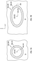
- an effective cross-section of each HX tube 26 may be changed from, for example, a circular geometry of FIG. 7A to an elongated geometry (e.g., an oval geometry) of FIG. 7B .
- the circular geometry of FIG. 7A is shown in a plane perpendicular to the HX tube centerline axis 102, 124.
- FIG. 7B is shown in a third reference plane (e.g., a y-z plane) which is angularly offset from the plane of FIG. 7A .
- Provision of the elongated geometry may facilitate a reduction in vortex shedding at a trailing edge 138 of the respective HX tube 26.
- canting the HX tubes 26 within the duct flowpath 52 increases available surface area for heat transfer between the first fluid and the second fluid.
- the present disclosure is not limited to the exemplary cross-sectional geometries shown in FIGS. 7A and 7B .
- each location 140A, 140B (generally referred to as "140") (see also FIG. 9 ) where one of the HX tubes (e.g., 26A or 26B) crosses over another one of the HX tubes (e.g., 26B or 26A), those HX tubes 26 may laterally engage (e.g., contact) one another.
- Providing engagement between the HX tubes 26 may effectively fix those HX tubes 26 to one another at the crossover locations 140.
- the engagement may thereby stiffen the HX tubes 26 and reduce an effective unsupported length of the HX tube 26 within the duct flowpath 52. Reducing the effective unsupported length may increase a natural resonant frequency of the of the respective HX tube 26.
- the crossing HX tubes 26 may alternatively be laterally spaced from one another in other embodiments.
- two or more of the crossing HX tubes 26A and 26B may be laterally connected to one another.
- the HX tubes 26, for example, at any one or more or all of the crossover locations 140 may be connected (e.g., tied) to one another.
- Each of the connections between the HX tubes 26 may be a rigid connection.
- the respective HX tubes 26, for example, may be bonded (e.g., brazed, welded or adhered) to one another, wire tied to one another, engage one another through a mechanical interference fit, etc.
- any one or more or each of the connections between the HX tubes 26 may each be a compliant connection.
- the respective HX tubes 26, for example, may be connected through a damper such as, but not limited to, a rubber band or strap. Similar to providing engagement between the HX tubes 26 as discussed above, the connections between the respective HX tubes 26 may stiffen the HX tubes 26 and/or shorten the effective unsupported length of the HX tube 26 within the duct flowpath 52.
- a damper such as, but not limited to, a rubber band or strap. Similar to providing engagement between the HX tubes 26 as discussed above, the connections between the respective HX tubes 26 may stiffen the HX tubes 26 and/or shorten the effective unsupported length of the HX tube 26 within the duct flowpath 52.
- the connections at the crossover locations 140 of FIG. 9 are located vertically between the first manifold wall 48 and the second manifold wall 49.
- the connections at the first crossover locations 140A are located vertically between the first manifold wall 48 and the second crossover locations 140B.
- the connections at the second crossover locations 140B are located vertically between the first crossover locations 140A and the second manifold wall 49.
- the HX duct 40 and its members 46-49 may be configured together is a monolithic body.
- the duct members 46-49 may be cast, machined and/or otherwise formed as a single unitary body.
- each of the HX tubes 26 is formed discrete from the monolithic body.
- the HX tubes 26 may then be assembled with the HX duct 40, for example, as described above. With such an arrangement, each of the HX tubes 26 may be a wrought tube.
- the present disclosure is not limited to such an exemplary heat exchanger construction.
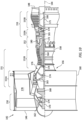
- FIG. 10 illustrates an exemplary embodiment of a gas turbine engine 142 with which the heat exchanger 20 may be included or may otherwise service.
- This turbine engine 142 extends along an axial centerline 144 between an upstream airflow inlet 146 and a downstream airflow exhaust 148.
- the turbine engine 142 includes a fan section 150, a compressor section 151, a combustor section 152 and a turbine section 153.
- the compressor section 151 includes a low pressure compressor (LPC) section 151A and a high pressure compressor (HPC) section 151B.
- the turbine section 153 includes a high pressure turbine (HPT) section 153A and a low pressure turbine (LPT) section 153B.
- the engine sections 150-153B are arranged sequentially along the axial centerline 144 within an engine housing 156.
- This engine housing 156 includes an inner case 158 (e.g., a core case) and an outer case 160 (e.g., a fan case).
- the inner case 158 may house one or more of the engine sections 151A-153B; e.g., an engine core.
- the outer case 160 may house at least the fan section 150.
- Each of the engine sections 150, 151A, 151B, 153A and 153B includes a respective bladed rotor 162-166.
- Each of these bladed rotors 162-166 includes a plurality of rotor blades arranged circumferentially around and connected to one or more respective rotor disks.
- the rotor blades may be formed integral with or mechanically fastened, welded, brazed, adhered and/or otherwise attached to the respective rotor disk(s).
- the fan rotor 162 is connected to a geartrain 168, for example, through a fan shaft 170.
- the geartrain 168 and the LPC rotor 163 are connected to and driven by the LPT rotor 166 through a low speed shaft 171.
- the HPC rotor 164 is connected to and driven by the HPT rotor 165 through a high speed shaft 172.
- the shafts 170-172 are rotatably supported by a plurality of bearings 174; e.g., rolling element and/or thrust bearings. Each of these bearings 174 is connected to the engine housing 156 by at least one stationary structure such as, for example, an annular support strut.
- This air is directed through the fan section 150 and into a core flowpath 176 and a bypass flowpath 178.
- the core flowpath 176 extends sequentially through the engine sections 151A-153B; e.g., the engine core.
- the air within the core flowpath 176 may be referred to as "core air”.
- the bypass flowpath 178 extends through a bypass duct, which bypasses the engine core.
- the air within the bypass flowpath 178 may be referred to as "bypass air”.
- the core air is compressed by the LPC rotor 163 and the HPC rotor 164 and directed into a combustion chamber 180 of a combustor in the combustor section 152.
- Fuel is injected into the combustion chamber 180 and mixed with the compressed core air to provide a fuel-air mixture.
- This fuel-air mixture is ignited and combustion products thereof flow through and sequentially cause the HPT rotor 165 and the LPT rotor 166 to rotate.
- the rotation of the HPT rotor 165 and the LPT rotor 166 respectively drive rotation of the HPC rotor 164 and the LPC rotor 163 and, thus, compression of the air received from a core airflow inlet.
- the rotation of the LPT rotor 166 also drives rotation of the fan rotor 162, which propels the bypass air through and out of the bypass flowpath 178.
- the propulsion of the bypass air may account for a majority of thrust generated by the turbine engine 142.
- the heat exchanger 20 may be included in various turbine engines other than the one described above as well as in other types of equipment.
- the heat exchanger 20, for example, may be included in a geared turbine engine where a geartrain connects one or more shafts to one or more rotors in a fan section, a compressor section and/or any other engine section.
- the heat exchanger 20 may be included in a turbine engine configured without a geartrain; e.g., a direct drive turbine engine.
- the heat exchanger 20 may be included in a turbine engine configured with a single spool, with two spools (e.g., see FIG. 10 ), or with more than two spools.
- the turbine engine may be configured as a turbofan engine, a turbojet engine, a turboprop engine, a turboshaft engine, a propfan engine, a pusher fan engine or any other type of turbine engine.
- the turbine engine may alternatively be configured as an auxiliary power unit (APU) or an industrial gas turbine engine.
- APU auxiliary power unit
- the present disclosure therefore is not limited to any particular types or configurations of turbine engines.
Landscapes
- Engineering & Computer Science (AREA)
- Physics & Mathematics (AREA)
- Thermal Sciences (AREA)
- Mechanical Engineering (AREA)
- General Engineering & Computer Science (AREA)
- Heat-Exchange Devices With Radiators And Conduit Assemblies (AREA)
Abstract
Description
- This disclosure relates generally to a heat exchange system and, more particularly, to a heat exchanger with multiple heat exchange tubes crossing a flowpath.
- Various types and configurations of heat exchangers are known in the art. While these known heat exchangers have various benefits, there is still room in the art for improvement. In particular, there is a need in the art for a heat exchanger which can reduce vibratory responses induced by a cross flow of fluid through the heat exchanger.
- According to an aspect of the present invention, a heat exchanger is provided that includes a duct and a plurality of tubes. The duct includes a flowpath, a first sidewall, a second sidewall, a first manifold wall and a second manifold wall. The flowpath extends longitudinally through the duct. The flowpath extends laterally within the duct between the first sidewall and the second sidewall. The flowpath extends vertically within the duct between the first manifold wall and the second manifold wall. The first manifold wall is configured to form a peripheral boundary of a first manifold plenum outside of the duct. The second manifold wall is configured to form a peripheral boundary of a second manifold plenum outside of the duct. The tubes extend vertically across the flowpath and are connected to the first manifold wall and the second manifold wall. Each of the tubes has a bore configured to fluidly couple the first manifold plenum to the second manifold plenum. The tubes include a first tube and a second tube. The first tube is adjacent and angularly offset from the second tube.
- According to another aspect of the present invention, another heat exchanger is provided that includes a first manifold, a second manifold and a plurality of tubes. The first manifold includes a first manifold wall and a first manifold plenum. The first manifold wall is between and partially forms the first manifold plenum and a flowpath. The second manifold includes a second manifold wall and a second manifold plenum. The second manifold wall is between and partially forms the second manifold plenum and the flowpath. The tubes extend vertically across the flowpath and are connected to the first manifold wall and the second manifold wall. Each of the tubes has an internal passage fluidly coupling the first manifold plenum to the second manifold plenum. The tubes include a first tube and a second tube that is angularly offset from the first tube within the flowpath. The first tube extends along a straight first trajectory out from the first manifold wall, through the flowpath and to the second manifold wall. The second tube extends along a straight second trajectory out from the first manifold wall, through the flowpath and to the second manifold wall.
- According to still another aspect of the present invention, another heat exchanger is provided that includes a first manifold, a second manifold and a plurality of tubes. The first manifold includes a first manifold wall and a first manifold plenum. The first manifold wall is between and partially forms the first manifold plenum and a flowpath. The second manifold includes a second manifold wall and a second manifold plenum. The second manifold wall is between and partially forms the second manifold plenum and the flowpath. The tubes extend vertically across the flowpath and are connected to the first manifold wall and the second manifold wall. Each of the tubes has an internal passage fluidly coupling the first manifold plenum to the second manifold plenum. The tubes include a first tube and a second tube. The first tube is angularly offset from the second tube at a first location vertically between the first manifold wall and the second manifold wall. The first tube is attached to the second tube at the first location. The internal passage of the first tube is fluidly uncoupled from the internal passage of the second tube vertically between the first manifold wall and the second manifold wall.
- The first tube may extend along a straight first trajectory out from the first manifold wall, through the flowpath and to the second manifold wall. In addition or alternatively, the second tube may extend along a straight second trajectory out from the first manifold wall, through the flowpath and to the second manifold wall.
- The first tube may extend along the straight first trajectory through the first manifold wall and/or the second manifold wall. In addition or alternatively, the second tube may extend along the straight second trajectory through the first manifold wall and/or the second manifold wall.
- The first tube may be angularly offset from the first manifold wall and/or the second manifold wall by a first acute angle. In addition or alternatively, the second tube may be angularly offset from the first manifold wall and/or the second manifold wall by a second acute angle.
- The heat exchanger may also include a heat exchanger housing including the first manifold wall and the second manifold wall. The flowpath may extend longitudinally through the heat exchanger housing.
- At least one of the tubes may be configured according to a heat exchange tube crossover parameter between 0.75 inches/crossover (1.9 cm/crossover) and 4.0 inches/crossover (10 cm/crossover).
- The first tube may be laterally adjacent the second tube.
- The first tube may engage the second tube.
- The first tube may be connected to the second tube at a first location within the flowpath vertically between the first manifold wall and the second manifold wall.
- The tubes may also include a third tube. The first tube may be adjacent and angularly offset from the third tube. The first tube may be connected to the third tube at a second location within the flowpath vertically between the first location and the second manifold wall.
- A connection between the first tube and the second tube at the first location may be a rigid connection.
- A connection between the first tube and the second tube at the first location may be a compliant connection.
- The bore of the first tube may be fluidly discrete from the bore of the second tube within the flowpath.
- The first tube may be angularly offset from the second tube by a first acute angle.
- The first tube may be angularly offset from the first manifold wall by a second acute angle.
- The second acute angle may be greater than the first acute angle.
- The first tube may also be angularly offset from the second manifold wall by the second acute angle.
- The first tube may extend along a straight first trajectory out of a first aperture in the first manifold wall, through the flowpath and into a first aperture in the second manifold wall.
- The second tube may extend along a straight second trajectory out of a second aperture in the first manifold wall, through the flowpath and into a second aperture in the second manifold wall.
- The tubes may be arranged into a plurality of first arrays and a plurality of second arrays that are laterally interposed with the first arrays. The tubes arranged in the first arrays may be parallel with one another. The tubes arranged in the second arrays may be parallel with one another. One of the first arrays may include the first tube. One of the second arrays may include the second tube.
- The duct may be configured as part of a monolithic body.
- The present disclosure may include any one or more of the individual features disclosed above and/or below alone or in any combination thereof.
- The foregoing features and the operation of the invention will become more apparent in light of the following description and the accompanying drawings.
-
-
FIG. 1 is a sectional illustration of a heat exchanger for a heat exchange system. -
FIG. 2 is another sectional illustration of the heat exchanger for the heat exchange system. -
FIG. 3 is a perspective illustration of a portion of the heat exchanger. -
FIG. 4 is a perspective cutaway illustration of a portion of the heat exchanger. -
FIG. 5 is a partial sectional illustration of a first heat exchange tube extending between and connected to a pair of manifold walls. -
FIG. 6 is a partial sectional illustration of a second heat exchange tube extending between and connected to the manifold walls. -
FIG. 7A is a cross-sectional illustration of a heat exchange tube in a plane perpendicular to a centerline axis of the heat exchanger tube; e.g., seeline 7A-7A inFIG. 5 or 6 . -
FIG. 7B is a cross-sectional illustration of the heat exchange tube ofFIG. 7A in an x-z plane; e.g., seeline 7B-7B inFIG. 5 or 6 . -
FIG. 8A is partial illustration of a pair of laterally adjacent heat exchange tubes laterally engaged at a point of crossover. -
FIG. 8B is a partial illustration of a pair of laterally adjacent heat exchange tubes laterally spaced at a point of crossover. -
FIG. 9 is a sectional illustration of the heat exchanger where laterally adjacent heat exchange tubes are connected to one another at one or more vertical locations. -
FIG. 10 is a side cutaway illustration of a turbine engine which may include the heat exchange system. -
FIGS. 1 and2 illustrate a heat exchanger 20 (e.g., a microtube heat exchanger) for aheat exchange system 22. Theheat exchange system 22 may be a cooling system or a heating system for a gas turbine engine. The present disclosure, however, is not limited to turbine engine applications. Theheat exchanger 20 ofFIG. 1 and2 includes a heat exchanger (HX)housing 24 and a plurality of heat exchange (HX)tubes - The
HX housing 24 ofFIG. 1 extends laterally (e.g., along an x-axis) between and to opposinglateral sides heat exchanger 20 and itsHX housing 24. TheHX housing 24 extends vertically (e.g., along a y-axis) between and to opposingvertical sides heat exchanger 20 and itsHX housing 24. Note, the term "vertical" is used herein to describe a depthwise direction and is not limited to a gravitational up/down direction. TheHX housing 24 ofFIG. 2 extends longitudinally (e.g., along a z-axis) between and to opposing longitudinal ends 36 and 38 of theheat exchanger 20 and itsHX housing 24. - The
HX housing 24 ofFIGS. 1 and2 includes a heat exchanger (HX)duct 40, afirst manifold 42 and asecond manifold 44. Referring toFIG. 1 , theHX duct 40 includes a ductfirst sidewall 46, a ductsecond sidewall 47, a ductfirst manifold wall 48 and a ductsecond manifold wall 49. These duct walls 46-49 are arranged together to provide theHX duct 40 with aninternal duct flowpath 52; see alsoFIG. 2 . - The duct sidewalls 46 and 47 of
FIG. 1 are respectively disposed at (e.g., on, adjacent or proximate) or towards the lateral sides 28 and 30. Each of theseduct sidewalls duct manifold walls duct sidewalls FIG. 1 is also connected to (e.g., formed integral with or otherwise attached to) theduct manifold walls duct sidewalls FIGS. 2 and3 extends longitudinally between and to the longitudinal ends 36 and 38. Each of theduct sidewalls FIG. 1 extends laterally between and to aninterior side respective duct sidewall exterior side respective duct sidewall interior side 54 of thefirst sidewall 46 forms a first lateral peripheral boundary of theduct flowpath 52 within theHX duct 40. Theinterior side 56 of thesecond sidewall 47 forms a second lateral peripheral boundary of theduct flowpath 52 within theHX duct 40, where the second lateral peripheral boundary is laterally opposite the first lateral peripheral boundary. - The
duct manifold walls FIG. 1 are respectively disposed at or towards thevertical sides duct manifold walls duct manifold walls FIG. 2 extends longitudinally between and to the longitudinal ends 36 and 38. Each of theduct manifold walls FIG. 1 extends vertically between and to aninterior side duct manifold wall exterior side duct manifold wall interior side 62 of thefirst manifold wall 48 forms a first vertical peripheral boundary of theduct flowpath 52 within theHX duct 40. Theinterior side 64 of thesecond manifold wall 49 forms a second vertical peripheral boundary of theduct flowpath 52 within theHX duct 40, where the second vertical peripheral boundary is vertically opposite the first vertical peripheral boundary. A surface at theexterior side 66 of thefirst manifold wall 48 may form a vertical peripheral boundary of afirst manifold plenum 70 within thefirst manifold 42. A surface at theexterior side 68 of thesecond manifold wall 49 may form a vertical peripheral boundary of asecond manifold plenum 72 within thesecond manifold 44. - Referring to
FIG. 2 , thefirst manifold wall 48 includes a plurality offirst apertures 74; e.g., through-holes. Each of thesefirst apertures 74 projects vertically through thefirst manifold wall 48. - The
second manifold wall 49 includes a plurality ofsecond apertures 76; e.g., through-holes. Each of thesesecond apertures 76 projects vertically through thesecond manifold wall 49. - The
duct flowpath 52 ofFIG. 1 extends laterally within theHX duct 40 between and to theduct sidewalls duct flowpath 52 ofFIG. 1 extends vertically within theHX duct 40 between and to theduct manifold walls duct flowpath 52 ofFIG. 2 extends longitudinally through theheat exchanger 20 and itsHX duct 40 between the longitudinal ends 36 and 38. - Referring to
FIG. 1 , thefirst manifold 42 is configured to form thefirst manifold plenum 70 vertically adjacent theHX duct 40. Thefirst manifold 42 ofFIG. 1 includes thefirst manifold wall 48 and afirst manifold structure 78; e.g., a cover, a cap, a fitting, etc. Thefirst manifold structure 78 is connected (e.g., attached) to thefirst manifold wall 48. Thefirst manifold plenum 70 is disposed vertically between and formed by thefirst manifold wall 48 and thefirst manifold structure 78. Thefirst manifold structure 78 ofFIG. 1 includes afirst port 80. Thisfirst port 80 is configured to fluidly couple thefirst manifold plenum 70 to afirst conduit 82 of theheat exchange system 22. For ease of description, thefirst port 80 may be described below as an inlet into thefirst manifold 42, and thefirst manifold plenum 70 may be described below as an inlet plenum. The present disclosure, however, is not limited to such an exemplary arrangement. - The
second manifold 44 is configured to form thesecond manifold plenum 72 vertically adjacent theHX duct 40. Thesecond manifold 44 ofFIG. 1 includes thesecond manifold wall 49 and asecond manifold structure 84; e.g., a cover, a cap, a fitting, etc. Thesecond manifold structure 84 is connected (e.g., attached) to thesecond manifold wall 49. Thesecond manifold plenum 72 is disposed vertically between and formed by thesecond manifold wall 49 and thesecond manifold structure 84. Thesecond manifold structure 84 ofFIG. 1 includes asecond port 86. Thissecond port 86 is configured to fluidly couple thesecond manifold plenum 72 to asecond conduit 88 of theheat exchange system 22. For ease of description, thesecond port 86 may be described below as an outlet into thesecond manifold 44, and thesecond manifold plenum 72 may be described below as an outlet plenum. The present disclosure, however, is not limited to such an exemplary arrangement. - Referring to
FIGS. 3 and4 , theHX tubes arrays tube array HX tubes HX tubes tube array respective tube array duct flowpath 52. TheHX tubes tube array first tube arrays 90A ofFIGS. 3 and4 are laterally interposed with thesecond tube arrays 90B. Each interiorfirst tube array 90A, for example, may be arranged laterally between a respective laterally neighboring (e.g., adjacent) pair of thesecond tube arrays 90B. Similarly, each interiorsecond tube array 90B may be arranged laterally between a respective laterally neighboring pair of thefirst tube arrays 90A. - Referring to
FIG. 2 , each of thefirst tubes 26A is canted in a first direction and each of thesecond tubes 26B is canted in an opposite second direction when viewed, for example, in a first reference plane; e.g., a y-z plane. With this arrangement, each of thefirst tubes 26A may longitudinally and/or vertically cross over one or more of the (e.g., laterally adjacent)second tubes 26B within theduct flowpath 52. Similarly, each of thesecond tubes 26B may longitudinally and/or vertically cross over one or more of the (e.g., laterally adjacent)first tubes 26A within theduct flowpath 52. Each of thefirst tubes 26A is thereby angularly offset from each respectivesecond tube 26B by aninter-tube angle - The
first tubes 26A and thesecond tubes 26B may be configured according to a heat exchange (HX) tube crossover parameter. This HX tube crossover parameter may be defined as a ratio of a longitudinal length of a HX tube to a number of times that HX tube crosses one or more other HX tubes. For example, referring toFIG. 2 , the first tube 26AA has a firstlongitudinal length 93A (seeFIG. 5 ) measured between the interior sides 62 and 64. This first tube 26AA ofFIG. 2 crosses over two othersecond tubes 26B at two locations when viewed, for example, in the reference plane ofFIG. 2 . Thus, the HX tube crossover parameter for the first tube 26AA is equal to firstlongitudinal length 93A (seeFIG. 5 ) divided by two. Similarly, the second tube 26BB has a secondlongitudinal length 93B (seeFIG. 5 ) measured between the interior sides 62 and 64. This second tube 26BB ofFIG. 2 crosses over two otherfirst tubes 26A at two locations when viewed, for example, in the reference plane ofFIG. 2 . Thus, the HX tube crossover parameter for the second tube 26BB is equal to secondlongitudinal length 93B (seeFIG. 5 ) divided by two. The HX tube crossover parameter for one or more of theHX tubes 26A and/or 26B may be between 0.75 inches/crossover (1.9 cm/crossover) and 4.0 inches/crossover (10 cm/crossover); e.g., between 0.75 inches/crossover (1.9 cm/crossover) and 1.5 inches/crossover (3.8 cm/crossover), between 1.5 inches/crossover (3.8 cm/crossover) and 3.0 inches/crossover (7.6 cm/crossover), or between 3.0 inches/crossover (7.6 cm/crossover) and 4.0 inches/crossover (10 cm/crossover). - Each of the
first tubes 26A ofFIG. 2 (see alsoFIG. 5 ) is angularly offset from thefirst manifold wall 48 and itsinterior side 62 by a first tube-first manifold wall offset angle 94 (e.g., a non-zero acute angle) when viewed, for example, in the first reference plane. Each of thefirst tubes 26A ofFIG. 2 is angularly offset from thesecond manifold wall 49 and itsinterior side 64 by a first tube-second manifold wall offset angle 96 (e.g., a non-zero acute angle) when viewed, for example, in the first reference plane. The first tube-second manifold wall offsetangle 96 may be equal to the first tube-first manifold wall offsetangle 94. However, these offsetangles angle 96 and the first tube-first manifold wall offsetangle 94, for example, may each be greater than the inter-tube angle 92. Each offsetangle - Referring to
FIG. 1 , each of thefirst tubes 26A may be angularly offset from thefirst manifold wall 48 and itsinterior side 62 by another first tube-first manifold wall offsetangle 98 when viewed, for example, in a second reference plane; e.g., a x-z plane. Each of thefirst tubes 26A may be angularly offset from thesecond manifold wall 49 and itsinterior side 64 by another first tube-second manifold wall offsetangle 100 when viewed, for example, in the second reference plane. The first tube-second manifold wall offsetangle 100 may be equal to the first tube-first manifold wall offsetangle 98. In the embodiment ofFIG. 1 , each offsetangle - Referring to
FIG. 5 , each of thefirst tubes 26A extends axially along afirst centerline axis 102 of the respectivefirst tube 26A between and to afirst end 104 of the respectivefirst tube 26A and asecond end 106 of the respectivefirst tube 26A. Eachfirst tube 26A has atubular sidewall 108 that forms an internal first passageway 110 (e.g., a bore, a channel, etc.) within the respectivefirst tube 26A. Thisfirst passageway 110 extends axially along thefirst centerline axis 102 through respectivefirst tube 26A from aninlet 112 into thefirst passageway 110 and anoutlet 114 from thefirst passageway 110. Theinlet 112 may be disposed at thefirst end 104. Theoutlet 114 may be disposed at thesecond end 106. Eachfirst tube 26A extends vertically across theduct flowpath 52 between thefirst manifold 42 and itsfirst manifold wall 48 and thesecond manifold 44 and itssecond manifold wall 49. Eachfirst tube 26A is mated with (e.g., projects into or through) a respective one of thefirst apertures 74. Eachfirst tube 26A is further mated with (e.g., projects into or through) a respective one of thesecond apertures 76. With this arrangement, eachinlet 112 is fluidly coupled with thefirst manifold plenum 70 and eachoutlet 114 is fluidly coupled with thesecond manifold plenum 72. Eachfirst tube 26A and itsfirst passageway 110 thereby fluidly couples thefirst manifold plenum 70 to thesecond manifold plenum 72. Here, eachfirst passageway 110 may form a fluidly discrete pathway from thefirst manifold plenum 70 to thesecond manifold plenum 72. - An entirety of
first centerline axis 102 may follow a straight trajectory. Eachfirst tube 26A may thereby also follow a straight trajectory. Eachfirst tube 26A, more particularly, may be configured as a straight tube; e.g., a tube without any bends, kinks or the like. Providing eachfirst tube 26A with such a straight-line geometry may facilitate mating the respectivefirst tube 26A with theapertures manifold walls first tube 26A into theHX housing 24 along its respectivefirst centerline axis 102. Following the inserting of thefirst tubes 26A, each of thefirst tubes 26A may be attached to themanifold walls first tube 26A and therespective manifold wall - Each of the
second tubes 26B ofFIG. 2 (see alsoFIG. 6 ) is angularly offset from thefirst manifold wall 48 and itsinterior side 62 by a second tube-first manifold wall offset angle 116 (e.g., a non-zero acute angle) when viewed, for example, in the first reference plane. Each of thesecond tubes 26B ofFIG. 2 is angularly offset from thesecond manifold wall 49 and itsinterior side 64 by a second tube-second manifold wall offset angle 118 (e.g., a non-zero acute angle) when viewed, for example, in the first reference plane. The second tube-second manifold wall offsetangle 118 may be equal to the second tube-first manifold wall offsetangle 116 and/or the offset angles 94 and/or 96. However, these offsetangles angle 118 and the second tube-first manifold wall offsetangle 116, for example, may each be greater than the inter-tube angle 92. Each offsetangle - Referring to
FIG. 1 , each of thesecond tubes 26B may be angularly offset from thefirst manifold wall 48 and itsinterior side 62 by another second tube-first manifold wall offsetangle 120 when viewed, for example, in the second reference plane. Each of thesecond tubes 26B may be angularly offset from thesecond manifold wall 49 and itsinterior side 64 by another second tube-second manifold wall offsetangle 122 when viewed, for example, in the second reference plane. The second tube-second manifold wall offsetangle 122 may be equal to the second tube-first manifold wall offsetangle 120. In the embodiment ofFIG. 1 , each offset angle is a right (90°) angle. The present disclosure, however, is not limited to such an exemplary arrangement. - Referring to
FIG. 6 , each of thesecond tubes 26B extends axially along asecond centerline axis 124 of the respectivesecond tube 26B between and to afirst end 126 of the respectivesecond tube 26B and asecond end 128 of the respectivesecond tube 26B. Eachsecond tube 26B has atubular sidewall 130 that forms an internal second passageway 132 (e.g., a bore, a channel, etc.) within the respectivesecond tube 26B. Thissecond passageway 132 extends axially along thesecond centerline axis 124 through respectivesecond tube 26B from aninlet 134 into thesecond passageway 132 and anoutlet 136 from thesecond passageway 132. Theinlet 134 may be disposed at thefirst end 126. Theoutlet 136 may be disposed at thesecond end 128. Eachsecond tube 26B extends vertically across theduct flowpath 52 between thefirst manifold 42 and itsfirst manifold wall 48 and thesecond manifold 44 and itssecond manifold wall 49. Eachsecond tube 26B is mated with (e.g., projects into or through) a respective one of thefirst apertures 74. Eachsecond tube 26B is further mated with (e.g., projects into or through) a respective one of thesecond apertures 76. With this arrangement, eachinlet 134 is fluidly coupled with thefirst manifold plenum 70 and eachoutlet 136 is fluidly coupled with thesecond manifold plenum 72. Eachsecond tube 26B and itssecond passageway 132 thereby fluidly couples thefirst manifold plenum 70 to thesecond manifold plenum 72. Here, eachsecond passageway 132 may form a fluidly discrete pathway from thefirst manifold plenum 70 to thesecond manifold plenum 72. - An entirety of
second centerline axis 124 may follow a straight trajectory. Eachsecond tube 26B may thereby also follow a straight trajectory. Eachsecond tube 26B, more particularly, may be configured as a straight tube; e.g., a tube without any bends, kinks or the like. Providing eachsecond tube 26B with such a straight-line geometry may facilitate mating the respectivesecond tube 26B with theapertures manifold walls second tube 26B into theHX housing 24 along its respectivesecond centerline axis 124. Following the inserting of thesecond tubes 26B, each of thesecond tubes 26B may be attached to themanifold walls second tube 26B and therespective manifold wall - With the foregoing arrangement, referring to
FIGS. 1 and2 , the HX tubes 26 form a second flowpath vertically across theHX duct 40 and between thefirst manifold 42 and thesecond manifold 44. This second flowpath is transverse to theduct flowpath 52. - During operation of the
heat exchanger 20 ofFIGS. 1 and2 , a first fluid (e.g., a gas and/or a liquid) is directed into theduct flowpath 52 and a second fluid (e.g., a gas and/or a liquid) is directed into the second flowpath. As the first fluid flows within theHX duct 40 and the second fluid flows within the HX tubes 26, each HX tube 26 may transfer heat energy between the first fluid and the second fluid. Theheat exchanger 20 may thereby heat the first fluid and cool the second fluid where the second fluid is warmer than the first fluid. Alternatively, theheat exchanger 20 may cool the first fluid and heat the second fluid where the first fluid is warmer than the second fluid. Examples of the heat exchange fluids include, but are not limited to, ambient air, compressed air, fuel, coolant and lubricant. - The flow of the first fluid through the
duct flowpath 52 may excite vibrations in the HX tubes 26. The excitation of these vibrations, however, can be reduced by canting the HX tubes 26 relative to the flow of the first fluid; e.g., the z-axis direction. In particular, by canting the HX tubes 26 as described above, an effective cross-section of each HX tube 26 may be changed from, for example, a circular geometry ofFIG. 7A to an elongated geometry (e.g., an oval geometry) ofFIG. 7B . Note, the circular geometry ofFIG. 7A is shown in a plane perpendicular to the HXtube centerline axis FIG. 7B is shown in a third reference plane (e.g., a y-z plane) which is angularly offset from the plane ofFIG. 7A . Provision of the elongated geometry may facilitate a reduction in vortex shedding at a trailingedge 138 of the respective HX tube 26. Furthermore, canting the HX tubes 26 within theduct flowpath 52 increases available surface area for heat transfer between the first fluid and the second fluid. The present disclosure, however, is not limited to the exemplary cross-sectional geometries shown inFIGS. 7A and 7B . - Referring to
FIG. 8A , at eachlocation FIG. 9 ) where one of the HX tubes (e.g., 26A or 26B) crosses over another one of the HX tubes (e.g., 26B or 26A), those HX tubes 26 may laterally engage (e.g., contact) one another. Providing engagement between the HX tubes 26 may effectively fix those HX tubes 26 to one another at the crossover locations 140. The engagement may thereby stiffen the HX tubes 26 and reduce an effective unsupported length of the HX tube 26 within theduct flowpath 52. Reducing the effective unsupported length may increase a natural resonant frequency of the of the respective HX tube 26. It is contemplated however, referring toFIG. 8B , the crossing HX tubes 26 may alternatively be laterally spaced from one another in other embodiments. - Referring to
FIG. 9 , two or more of the crossingHX tubes duct flowpath 52. - The connections at the crossover locations 140 of
FIG. 9 are located vertically between thefirst manifold wall 48 and thesecond manifold wall 49. The connections at thefirst crossover locations 140A are located vertically between thefirst manifold wall 48 and thesecond crossover locations 140B. The connections at thesecond crossover locations 140B are located vertically between thefirst crossover locations 140A and thesecond manifold wall 49. - Referring to
FIGS. 3 and4 , in some embodiments, theHX duct 40 and its members 46-49 may be configured together is a monolithic body. The duct members 46-49, for example, may be cast, machined and/or otherwise formed as a single unitary body. - In some embodiments, each of the HX tubes 26 is formed discrete from the monolithic body. The HX tubes 26 may then be assembled with the
HX duct 40, for example, as described above. With such an arrangement, each of the HX tubes 26 may be a wrought tube. The present disclosure, however, is not limited to such an exemplary heat exchanger construction. -
FIG. 10 illustrates an exemplary embodiment of agas turbine engine 142 with which theheat exchanger 20 may be included or may otherwise service. Thisturbine engine 142 extends along anaxial centerline 144 between anupstream airflow inlet 146 and adownstream airflow exhaust 148. Theturbine engine 142 includes afan section 150, acompressor section 151, acombustor section 152 and aturbine section 153. Thecompressor section 151 includes a low pressure compressor (LPC)section 151A and a high pressure compressor (HPC)section 151B. Theturbine section 153 includes a high pressure turbine (HPT)section 153A and a low pressure turbine (LPT)section 153B. - The engine sections 150-153B are arranged sequentially along the
axial centerline 144 within anengine housing 156. Thisengine housing 156 includes an inner case 158 (e.g., a core case) and an outer case 160 (e.g., a fan case). Theinner case 158 may house one or more of theengine sections 151A-153B; e.g., an engine core. Theouter case 160 may house at least thefan section 150. - Each of the
engine sections - The
fan rotor 162 is connected to ageartrain 168, for example, through afan shaft 170. Thegeartrain 168 and theLPC rotor 163 are connected to and driven by theLPT rotor 166 through alow speed shaft 171. TheHPC rotor 164 is connected to and driven by theHPT rotor 165 through ahigh speed shaft 172. The shafts 170-172 are rotatably supported by a plurality ofbearings 174; e.g., rolling element and/or thrust bearings. Each of thesebearings 174 is connected to theengine housing 156 by at least one stationary structure such as, for example, an annular support strut. - During operation, air enters the
turbine engine 142 through theairflow inlet 146. This air is directed through thefan section 150 and into acore flowpath 176 and abypass flowpath 178. Thecore flowpath 176 extends sequentially through theengine sections 151A-153B; e.g., the engine core. The air within thecore flowpath 176 may be referred to as "core air". Thebypass flowpath 178 extends through a bypass duct, which bypasses the engine core. The air within thebypass flowpath 178 may be referred to as "bypass air". - The core air is compressed by the
LPC rotor 163 and theHPC rotor 164 and directed into acombustion chamber 180 of a combustor in thecombustor section 152. Fuel is injected into thecombustion chamber 180 and mixed with the compressed core air to provide a fuel-air mixture. This fuel-air mixture is ignited and combustion products thereof flow through and sequentially cause theHPT rotor 165 and theLPT rotor 166 to rotate. The rotation of theHPT rotor 165 and theLPT rotor 166 respectively drive rotation of theHPC rotor 164 and theLPC rotor 163 and, thus, compression of the air received from a core airflow inlet. The rotation of theLPT rotor 166 also drives rotation of thefan rotor 162, which propels the bypass air through and out of thebypass flowpath 178. The propulsion of the bypass air may account for a majority of thrust generated by theturbine engine 142. - The
heat exchanger 20 may be included in various turbine engines other than the one described above as well as in other types of equipment. Theheat exchanger 20, for example, may be included in a geared turbine engine where a geartrain connects one or more shafts to one or more rotors in a fan section, a compressor section and/or any other engine section. Alternatively, theheat exchanger 20 may be included in a turbine engine configured without a geartrain; e.g., a direct drive turbine engine. Theheat exchanger 20 may be included in a turbine engine configured with a single spool, with two spools (e.g., seeFIG. 10 ), or with more than two spools. The turbine engine may be configured as a turbofan engine, a turbojet engine, a turboprop engine, a turboshaft engine, a propfan engine, a pusher fan engine or any other type of turbine engine. The turbine engine may alternatively be configured as an auxiliary power unit (APU) or an industrial gas turbine engine. The present disclosure therefore is not limited to any particular types or configurations of turbine engines. - While various embodiments of the present disclosure have been described, it will be apparent to those of ordinary skill in the art that many more embodiments and implementations are possible within the scope of the disclosure. For example, the present disclosure as described herein includes several aspects and embodiments that include particular features. Although these features may be described individually, it is within the scope of the present disclosure that some or all of these features may be combined with any one of the aspects and remain within the scope of the disclosure. Accordingly, the present disclosure is not to be restricted except in light of the attached claims and their equivalents.
-
- 1. A heat exchanger, comprising:
- a first manifold including a first manifold wall and a first manifold plenum, the first manifold wall between and partially forming the first manifold plenum and a flowpath;
- a second manifold including a second manifold wall and a second manifold plenum, the second manifold wall between and partially forming the second manifold plenum and the flowpath; and
- a plurality of tubes extending vertically across the flowpath and connected to the first manifold wall and the second manifold wall, each of the plurality of tubes having an internal passage fluidly coupling the first manifold plenum to the second manifold plenum, and the plurality of tubes including a first tube and a second tube that is angularly offset from the first tube within the flowpath;
- the first tube extending along a straight first trajectory out from the first manifold wall, through the flowpath and to the second manifold wall; and
- the second tube extending along a straight second trajectory out from the first manifold wall, through the flowpath and to the second manifold wall.
- 2. The heat exchanger of clause 1, wherein at least one of
- the first tube extends along the straight first trajectory through at least one of the first manifold wall or the second manifold wall; or
- the second tube extends along the straight second trajectory through at least one of the first manifold wall or the second manifold wall.
- 3. The heat exchanger of clause 1 or 2, further comprising:
- a heat exchanger housing including the first manifold wall and the second manifold wall;
- the flowpath extending longitudinally through the heat exchanger housing.
- 4. A heat exchanger, comprising:
- a first manifold including a first manifold wall and a first manifold plenum, the first manifold wall between and partially forming the first manifold plenum and a flowpath;
- a second manifold including a second manifold wall and a second manifold plenum, the second manifold wall between and partially forming the second manifold plenum and the flowpath; and
- a plurality of tubes extending vertically across the flowpath and connected to the first manifold wall and the second manifold wall, each of the plurality of tubes having an internal passage fluidly coupling the first manifold plenum to the second manifold plenum, and the plurality of tubes including a first tube and a second tube;
- the first tube angularly offset from the second tube at a first location vertically between the first manifold wall and the second manifold wall;
- the first tube attached to the second tube at the first location; and
- the internal passage of the first tube fluidly uncoupled from the internal passage of the second tube vertically between the first manifold wall and the second manifold wall.
- 5. The heat exchanger of clause 4, wherein at least one of
- the first tube extends along a straight first trajectory out from the first manifold wall, through the flowpath and to the second manifold wall; or
- the second tube extends along a straight second trajectory out from the first manifold wall, through the flowpath and to the second manifold wall.
Claims (15)
- A heat exchanger (20), comprising:a duct (40) including a flowpath (52), a first sidewall (46), a second sidewall (47), a first manifold wall (48) and a second manifold wall (49), the flowpath (52) extending longitudinally through the duct (40), the flowpath (52) extending laterally within the duct (40) between the first sidewall (46) and the second sidewall (47), the flowpath (52) extending vertically within the duct (40) between the first manifold wall (48) and the second manifold wall (49), the first manifold wall (48) configured to form a peripheral boundary of a first manifold plenum (70) outside of the duct (40), and the second manifold wall (49) configured to form a peripheral boundary of a second manifold plenum (72) outside of the duct (40); anda plurality of tubes (26) extending vertically across the flowpath (52) and connected to the first manifold wall (48) and the second manifold wall (49), each of the plurality of tubes (26) having a bore (110) configured to fluidly couple the first manifold plenum (70) to the second manifold plenum (72), the plurality of tubes (26) including a first tube (26A) and a second tube (26B), and the first tube (26A) adjacent and angularly offset from the second tube (26B).
- The heat exchanger of claim 1, wherein at least one of the plurality of tubes (26) is configured according to a heat exchange tube crossover parameter between 0.75 inches/crossover (1.9 cm/crossover) and 4.0 inches/crossover (10 cm/crossover).
- The heat exchanger of claim 1 or 2, wherein the first tube (26A) is laterally adjacent the second tube (26B).
- The heat exchanger of claim 1, 2 or 3, wherein the first tube (26A) engages the second tube (26B).
- The heat exchanger of any preceding claim, wherein the first tube (26A) is connected to the second tube (26A) at a first location (140A) within the flowpath vertically between the first manifold wall (48) and the second manifold wall (49).
- The heat exchanger of claim 5, whereinthe plurality of tubes (26) further includes a third tube (26);the first tube (26A) is adjacent and angularly offset from the third tube (26); andthe first tube (26A) is connected to the third tube (26) at a second location (140B) within the flowpath (52) vertically between the first location (140A) and the second manifold wall (49).
- The heat exchanger of claim 5 or 6, wherein a connection between the first tube (26A) and the second tube (26B) at the first location (140A) is a rigid connection.
- The heat exchanger of claim 5 or 6, wherein a connection between the first tube (26A) and the second tube (26B) at the first location (140A) is a compliant connection.
- The heat exchanger of any preceding claim, wherein the bore (110) of the first tube (26A) is fluidly discrete from the bore (110) of the second tube (26B) within the flowpath.
- The heat exchanger of claim 1, wherein the first tube (26A) is angularly offset from the second tube (26B) by a first acute angle (92).
- The heat exchanger of claim 10, wherein the first tube (26A) is angularly offset from the first manifold wall (48) by a second acute angle (94).
- The heat exchanger of claim 11, wherein the second acute angle (94) is greater than the first acute angle (92).
- The heat exchanger of any preceding claim, wherein the first tube (26A) extends along a straight first trajectory out of a first aperture (74) in the first manifold wall (48), through the flowpath (52) and into a first aperture (76) in the second manifold wall (49).
- The heat exchanger of any preceding claim, wherein the second tube (26B) extends along a straight second trajectory out of a second aperture (74) in the first manifold wall (48), through the flowpath (52) and into a second aperture (76) in the second manifold wall (49).
- The heat exchanger of any preceding claim, wherein:the plurality of tubes (26) are arranged into a plurality of first arrays (90A) and a plurality of second arrays (90B) that are laterally interposed with the plurality of first arrays (90A);the plurality of tubes (26) arranged in the plurality of first arrays (90A) are parallel with one another;the plurality of tubes (26) arranged in the plurality of second arrays (90B) are parallel with one another;one of the plurality of first arrays (90A) includes the first tube (26A); andone of the plurality of second arrays (90B) includes the second tube (26B).
Applications Claiming Priority (1)
| Application Number | Priority Date | Filing Date | Title |
|---|---|---|---|
| US18/119,130 US20240302101A1 (en) | 2023-03-08 | 2023-03-08 | Heat exchanger with crossing heat exchange tubes |
Publications (2)
| Publication Number | Publication Date |
|---|---|
| EP4428478A1 true EP4428478A1 (en) | 2024-09-11 |
| EP4428478B1 EP4428478B1 (en) | 2026-02-04 |
Family
ID=90246039
Family Applications (1)
| Application Number | Title | Priority Date | Filing Date |
|---|---|---|---|
| EP24162445.1A Active EP4428478B1 (en) | 2023-03-08 | 2024-03-08 | Heat exchanger with crossing heat exchange tubes |
Country Status (2)
| Country | Link |
|---|---|
| US (1) | US20240302101A1 (en) |
| EP (1) | EP4428478B1 (en) |
Families Citing this family (1)
| Publication number | Priority date | Publication date | Assignee | Title |
|---|---|---|---|---|
| CN120651025B (en) * | 2025-07-30 | 2026-02-10 | 华能国际电力股份有限公司井冈山电厂 | Preheating facility of demineralized water of power plant |
Citations (5)
| Publication number | Priority date | Publication date | Assignee | Title |
|---|---|---|---|---|
| US20140251585A1 (en) * | 2013-03-05 | 2014-09-11 | The Boeing Company | Micro-lattice Cross-flow Heat Exchangers for Aircraft |
| US20150083375A1 (en) * | 2013-09-20 | 2015-03-26 | Rolf Heusser | Device for Mixing and Heat Exchange |
| US20160202003A1 (en) * | 2014-10-07 | 2016-07-14 | General Electric Company | Heat exchanger including furcating unit cells |
| US20190093954A1 (en) * | 2017-09-22 | 2019-03-28 | Honeywell International Inc. | Heat exchanger with interspersed arrangement of cross-flow structures |
| US20210055064A1 (en) * | 2018-03-09 | 2021-02-25 | Bae Systems Plc | Heat exchanger |
Family Cites Families (5)
| Publication number | Priority date | Publication date | Assignee | Title |
|---|---|---|---|---|
| JPS5158749A (en) * | 1974-11-20 | 1976-05-22 | Mitsubishi Heavy Ind Ltd | |
| DE3906241A1 (en) * | 1989-02-28 | 1990-08-30 | Mtu Muenchen Gmbh | HEAT EXCHANGER WITH A TUBE MATRIX |
| JP2006292283A (en) * | 2005-04-11 | 2006-10-26 | Matsushita Electric Ind Co Ltd | Heat exchanger |
| CN106122925A (en) * | 2016-08-12 | 2016-11-16 | 无锡欧玛森远洋工程设备有限公司 | A kind of Industrial Boiler heat exchange coil |
| CN110822942B (en) * | 2019-11-29 | 2021-04-09 | 陕西益信伟创智能科技有限公司 | Three-dimensional cobweb laminated tube type heat exchanger based on bionics |
-
2023
- 2023-03-08 US US18/119,130 patent/US20240302101A1/en active Pending
-
2024
- 2024-03-08 EP EP24162445.1A patent/EP4428478B1/en active Active
Patent Citations (5)
| Publication number | Priority date | Publication date | Assignee | Title |
|---|---|---|---|---|
| US20140251585A1 (en) * | 2013-03-05 | 2014-09-11 | The Boeing Company | Micro-lattice Cross-flow Heat Exchangers for Aircraft |
| US20150083375A1 (en) * | 2013-09-20 | 2015-03-26 | Rolf Heusser | Device for Mixing and Heat Exchange |
| US20160202003A1 (en) * | 2014-10-07 | 2016-07-14 | General Electric Company | Heat exchanger including furcating unit cells |
| US20190093954A1 (en) * | 2017-09-22 | 2019-03-28 | Honeywell International Inc. | Heat exchanger with interspersed arrangement of cross-flow structures |
| US20210055064A1 (en) * | 2018-03-09 | 2021-02-25 | Bae Systems Plc | Heat exchanger |
Also Published As
| Publication number | Publication date |
|---|---|
| US20240302101A1 (en) | 2024-09-12 |
| EP4428478B1 (en) | 2026-02-04 |
Similar Documents
| Publication | Publication Date | Title |
|---|---|---|
| JP5866090B2 (en) | Airfoil integrated heat exchanger for gas turbine engine | |
| CN109415945B (en) | Modular annular heat exchanger | |
| US9777963B2 (en) | Method and system for radial tubular heat exchangers | |
| US7775031B2 (en) | Recuperator for aircraft turbine engines | |
| CN105222616B (en) | Method and system for radial tubular tube heat exchanger | |
| EP2011988A2 (en) | Heat exchanger for a turbine engine | |
| US12297775B2 (en) | Aircraft heat exchanger panel array interconnection | |
| US11187412B2 (en) | Flow control wall assembly for heat engine | |
| US10018075B2 (en) | Methods for positioning neighboring nozzles of a gas turbine engine | |
| EP4428478B1 (en) | Heat exchanger with crossing heat exchange tubes | |
| EP2519721B1 (en) | Damper seal | |
| US12169102B2 (en) | Plumbing with internal flow guides | |
| EP3722723A1 (en) | Curved heat exchanger | |
| EP4089356B1 (en) | Heat exchanger tube support | |
| US20250243810A1 (en) | Heat exchanger for a gas turbine engine | |
| EP4361423A2 (en) | Gas turbine engine component with integral heat exchanger | |
| EP4462061A1 (en) | Modular heat exchanger for an aircraft powerplant | |
| US11021961B2 (en) | Rotor assembly thermal attenuation structure and system | |
| US12286899B2 (en) | Trailing edge cooling circuit | |
| JP2023138907A (en) | System and method for thermally shielding components in the exhaust gas stream from a gas turbine |
Legal Events
| Date | Code | Title | Description |
|---|---|---|---|
| PUAI | Public reference made under article 153(3) epc to a published international application that has entered the european phase |
Free format text: ORIGINAL CODE: 0009012 |
|
| STAA | Information on the status of an ep patent application or granted ep patent |
Free format text: STATUS: THE APPLICATION HAS BEEN PUBLISHED |
|
| AK | Designated contracting states |
Kind code of ref document: A1 Designated state(s): AL AT BE BG CH CY CZ DE DK EE ES FI FR GB GR HR HU IE IS IT LI LT LU LV MC ME MK MT NL NO PL PT RO RS SE SI SK SM TR |
|
| STAA | Information on the status of an ep patent application or granted ep patent |
Free format text: STATUS: REQUEST FOR EXAMINATION WAS MADE |
|
| 17P | Request for examination filed |
Effective date: 20250311 |
|
| GRAP | Despatch of communication of intention to grant a patent |
Free format text: ORIGINAL CODE: EPIDOSNIGR1 |
|
| STAA | Information on the status of an ep patent application or granted ep patent |
Free format text: STATUS: GRANT OF PATENT IS INTENDED |
|
| INTG | Intention to grant announced |
Effective date: 20250826 |
|
| GRAS | Grant fee paid |
Free format text: ORIGINAL CODE: EPIDOSNIGR3 |
|
| GRAA | (expected) grant |
Free format text: ORIGINAL CODE: 0009210 |
|
| STAA | Information on the status of an ep patent application or granted ep patent |
Free format text: STATUS: THE PATENT HAS BEEN GRANTED |
|
| RIN1 | Information on inventor provided before grant (corrected) |
Inventor name: SOBANSKI, JON E. Inventor name: SNYDER, JACOB C. |
|
| AK | Designated contracting states |
Kind code of ref document: B1 Designated state(s): AL AT BE BG CH CY CZ DE DK EE ES FI FR GB GR HR HU IE IS IT LI LT LU LV MC ME MK MT NL NO PL PT RO RS SE SI SK SM TR |
|
| REG | Reference to a national code |
Ref country code: CH Ref legal event code: F10 Free format text: ST27 STATUS EVENT CODE: U-0-0-F10-F00 (AS PROVIDED BY THE NATIONAL OFFICE) Effective date: 20260204 Ref country code: GB Ref legal event code: FG4D |
|
| REG | Reference to a national code |
Ref country code: DE Ref legal event code: R096 Ref document number: 602024002346 Country of ref document: DE |
|
| REG | Reference to a national code |
Ref country code: IE Ref legal event code: FG4D |
|
| PGFP | Annual fee paid to national office [announced via postgrant information from national office to epo] |
Ref country code: DE Payment date: 20260219 Year of fee payment: 3 |
|
| PGFP | Annual fee paid to national office [announced via postgrant information from national office to epo] |
Ref country code: AT Payment date: 20260301 Year of fee payment: 3 |
|
| PGFP | Annual fee paid to national office [announced via postgrant information from national office to epo] |
Ref country code: FR Payment date: 20260319 Year of fee payment: 3 |