EP4428456A1 - Outdoor unit of air conditioner - Google Patents
Outdoor unit of air conditioner Download PDFInfo
- Publication number
- EP4428456A1 EP4428456A1 EP23160663.3A EP23160663A EP4428456A1 EP 4428456 A1 EP4428456 A1 EP 4428456A1 EP 23160663 A EP23160663 A EP 23160663A EP 4428456 A1 EP4428456 A1 EP 4428456A1
- Authority
- EP
- European Patent Office
- Prior art keywords
- support member
- electric component
- component box
- outdoor unit
- air conditioner
- Prior art date
- Legal status (The legal status is an assumption and is not a legal conclusion. Google has not performed a legal analysis and makes no representation as to the accuracy of the status listed.)
- Pending
Links
Images




Classifications
-
- F—MECHANICAL ENGINEERING; LIGHTING; HEATING; WEAPONS; BLASTING
- F24—HEATING; RANGES; VENTILATING
- F24F—AIR-CONDITIONING; AIR-HUMIDIFICATION; VENTILATION; USE OF AIR CURRENTS FOR SCREENING
- F24F1/00—Room units for air-conditioning, e.g. separate or self-contained units or units receiving primary air from a central station
- F24F1/06—Separate outdoor units, e.g. outdoor unit to be linked to a separate room comprising a compressor and a heat exchanger
- F24F1/20—Electric components for separate outdoor units
- F24F1/22—Arrangement or mounting thereof
-
- F—MECHANICAL ENGINEERING; LIGHTING; HEATING; WEAPONS; BLASTING
- F24—HEATING; RANGES; VENTILATING
- F24F—AIR-CONDITIONING; AIR-HUMIDIFICATION; VENTILATION; USE OF AIR CURRENTS FOR SCREENING
- F24F1/00—Room units for air-conditioning, e.g. separate or self-contained units or units receiving primary air from a central station
- F24F1/06—Separate outdoor units, e.g. outdoor unit to be linked to a separate room comprising a compressor and a heat exchanger
- F24F1/46—Component arrangements in separate outdoor units
-
- F—MECHANICAL ENGINEERING; LIGHTING; HEATING; WEAPONS; BLASTING
- F24—HEATING; RANGES; VENTILATING
- F24F—AIR-CONDITIONING; AIR-HUMIDIFICATION; VENTILATION; USE OF AIR CURRENTS FOR SCREENING
- F24F1/00—Room units for air-conditioning, e.g. separate or self-contained units or units receiving primary air from a central station
- F24F1/06—Separate outdoor units, e.g. outdoor unit to be linked to a separate room comprising a compressor and a heat exchanger
- F24F1/56—Casing or covers of separate outdoor units, e.g. fan guards
-
- F—MECHANICAL ENGINEERING; LIGHTING; HEATING; WEAPONS; BLASTING
- F24—HEATING; RANGES; VENTILATING
- F24F—AIR-CONDITIONING; AIR-HUMIDIFICATION; VENTILATION; USE OF AIR CURRENTS FOR SCREENING
- F24F13/00—Details common to, or for air-conditioning, air-humidification, ventilation or use of air currents for screening
- F24F13/32—Supports for air-conditioning, air-humidification or ventilation units
Definitions
- the present disclosure relates to an outdoor unit of an air conditioner.
- Japanese Laid-Open Patent Publication No. 2006-226644 discloses an outdoor unit of an air conditioner.
- the outdoor unit includes an electric component box supported by supports for a fan motor and a partition plate (shielding plate) zoning a fan chamber (chamber accommodating a fan).
- the electric component box is supported by the supports for the fan motor and the partition plate zoning the fan chamber. Disposition of the supports and the partition plate is influenced by sizes of other components. This may lead to difficulty in securing a span between supporting positions, and difficulty in stable support of a large electric component box.
- the present disclosure provides an outdoor unit of an air conditioner, which achieves stable support of even a large electric component box.
- An outdoor unit corresponds to an outdoor unit of an air conditioner, and includes a fan motor, a partition plate, a first support member, a second support member, and an electric component box.
- the fan motor drives a fan.
- the partition plate zones a fan chamber accommodating the fan.
- the first support member supports the fan motor.
- the first support member and the second support member support the electric component box.
- the outdoor unit supports the electric component box by means of the first support member supporting the fan motor and the second support member provided separately from the partition plate. Unlike the partition plate, the second support member is positioned relatively freely without being influenced by sizes of other components. The outdoor unit can thus freely position the second support member in accordance with a size of the electric component box so as to stably support even the electric component box having a large size.
- An outdoor unit according to a second aspect is the outdoor unit according to the first aspect, in which the second support member is disposed opposite to the partition plate with the first support member being interposed therebetween.
- An outdoor unit according to a third aspect is the outdoor unit according to the first or second aspect, in which the first support member and the second support member are aligned in a longitudinal direction of the electric component box.
- the outdoor unit can thus stably support even the electric component box elongated horizontally.
- An outdoor unit is the outdoor unit according to any one of the first to third aspects, in which the first support member has a first supporting stand.
- the second support member includes a second supporting stand. The first supporting stand and the second supporting stand support a bottom surface of the electric component box.
- the outdoor unit can thus stably support the electric component box by means of the first supporting stand and the second supporting stand.
- An outdoor unit according to a fifth aspect is the outdoor unit according to the fourth aspect, in which the first supporting stand and the second supporting stand each have an opposed surface opposed to a side surface of the electric component box.
- the opposed surface regulates horizontal movement of the electric component box.
- the outdoor unit can thus stably support the electric component box.
- An outdoor unit according to a sixth aspect is the outdoor unit according to the fifth aspect, in which the opposed surface is provided with a projection regulating movement of the electric component box.
- the projection is configured to set the electric component box at a stable position on the first supporting stand.
- the outdoor unit can thus stably support the electric component box.
- An outdoor unit according to a seventh aspect is the outdoor unit according to any one of the first to sixth aspects, in which the partition plate supports the electric component box.
- the electric component box is supported by the partition plate as well as by the first support member and the second support member.
- the outdoor unit can thus stably support the electric component box.
- An outdoor unit according to an eighth aspect is the outdoor unit according to the seventh aspect, in which the partition plate includes a third support member.
- the third support member supports the bottom surface of the electric component box.
- the electric component box is supported by the third support member as well as by the first support member and the second support member.
- the outdoor unit can thus stably support the electric component box.
- An outdoor unit is the outdoor unit according to the fourth aspect, and further includes a first heat exchanger.
- the first supporting stand and the second supporting stand each have a bottom surface disposed below an upper end of the first heat exchanger in a vertical direction.
- the electric component box has an upper surface that is accordingly inhibited from projecting upward from the upper end of the first heat exchanger. This inhibits increase in size of the outdoor unit.
- An outdoor unit according to a tenth aspect is the outdoor unit according to the ninth aspect, in which the electric component box is supported to have the upper surface positioned below the upper end of the first heat exchanger in the vertical direction.
- the upper surface of the electric component box accordingly does not project upward from the upper end of the first heat exchanger. This effectively inhibits increase in size of the outdoor unit.
- An outdoor unit according to an eleventh aspect is the outdoor unit according to any one of the first to tenth aspects, in which the electric component box is 15 kg or more in weight.
- the outdoor unit can stably support even the electric component box large enough to have 15 kg or more in weight.
- An outdoor unit according to a twelfth aspect is the outdoor unit according to any one of the first to eleventh aspects, in which the electric component box is a rectangular parallelepiped and has six surfaces each closed by 90% or more in terms of area.
- the outdoor unit can inhibit any refrigerant leaking from a refrigerant circuit from flowing into the electric component box.
- An outdoor unit is the outdoor unit according to any one of the first to twelfth aspects, in which the first support member and the second support member are each disposed to have a longitudinal direction matching the vertical direction.
- the first support member and the second support member are disposed such that a first center axis of the first support member and a second center axis of the second support member sandwich a horizontal center portion of the electric component box in a front view.
- the outdoor unit can thus stably support the electric component box.
- FIG. 1 is a schematic configuration diagram of an air conditioner 100 including an outdoor unit 90 according to an embodiment.
- the air conditioner 100 is configured to cool or heat a heating medium flowing in a heating medium circuit 30 by means of a refrigerant flowing in a refrigerant circuit 10, and condition air by means of the heating medium cooled or heated by the refrigerant.
- the heating medium flowing in the heating medium circuit 30 is water (hereinafter, the heating medium circuit 30 may be called a water circuit 30) in the present embodiment. Water flowing in the water circuit 30 should not be limited to pure water, but may alternatively be brine or the like.
- brine examples include, for example, an aqueous solution of calcium chloride, an aqueous solution of ethylene glycol, an aqueous solution of propylene glycol, etc.
- the following description exemplifies a case where the air conditioner 100 is configured to execute cooling operation and heating operation.
- the air conditioner 100 principally includes the outdoor unit 90 and a utilization facility 34.
- the outdoor unit 90 is disposed in an outdoor space such as on a roof of a building or around the building.
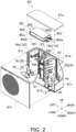
- FIG. 2 is an exploded view of the outdoor unit 90.
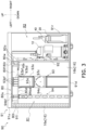
- FIG. 3 is a front view of the outdoor unit 90.
- FIG. 4 is a plan view of the outdoor unit 90.
- the outdoor unit 90 principally includes a case 91, a partition plate 92, a first support member 93, a second support member 94, the refrigerant circuit 10, part of the water circuit 30 (including a gas-liquid separator 40 connected to the water circuit 30), a fan unit 60, and an electric component box 80.
- FIG. 3 does not depict a front surface 91f (to be described later) of the case 91 and the fan unit 60.
- FIG. 4 does not depict an upper surface 91u (to be described later) of the case 91.
- Upright, transverse, and anteroposterior directions to be referred to in the following description correspond to directions indicated by arrows in FIG. 2 to FIG. 7 .
- the case 91 accommodates, in an internal space R, the partition plate 92, the first support member 93, the second support member 94, the refrigerant circuit 10, part of the water circuit 30 (including the gas-liquid separator 40 connected to the water circuit 30), the fan unit 60, and the electric component box 80.
- the case 91 has a substantially rectangular parallelepiped shape, and has the upper surface 91u, the front surface 91f, a rear surface 91b, a left surface 911, a right surface 91r, and a bottom surface 91d.
- the upper surface 91u has a substantially rectangular shape and covers the space R from above.
- the front surface 91f has a substantially rectangular shape and covers the space R from ahead.
- the front surface 91f is provided, at around the center, with a circular opening (grill) allowing an air flow generated by the fan unit 60 to pass therethrough.
- the rear surface 91b has a substantially rectangular shape and covers the space R from behind.
- the left surface 91l has a substantially rectangular shape and covers the space R from left.
- the right surface 91r has a substantially rectangular shape and covers the space R from right.
- the bottom surface 91d has a rectangular shape and covers the space R from below.
- the partition plate 92 is a plate-shaped member zoning a fan chamber R1 and a machine chamber R2 in the space R. Specifically, the partition plate 92 is disposed to transversely divide the space R into two portions. In the space R according to the present embodiment, a left portion of the partition plate 92 corresponds to the fan chamber R1 and a right portion of the partition plate 92 corresponds to the machine chamber R2.
- the partition plate 92 is provided with a plurality of openings 92a allowing wires 80w (to be described later) extending from the electric component box 80 to pass therethrough.
- the openings 92a are positioned to be opposed to a right surface 80r (to be described later) of the electric component box 80 as a side surface close to the partition plate 92.
- the partition plate 92 supports the electric component box 80.
- the partition plate 92 includes a third support member 92b supporting a bottom surface 80d (to be described later) of the electric component box 80.
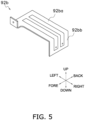
- FIG. 5 is a perspective view of the third support member 92b.
- the third support member 92b is a plate-shaped member having a first surface 92ba and a second surface 92bb.
- the first surface 92ba supports the bottom surface 80d of the electric component box 80.
- the first surface 92ba extends from the partition plate 92 toward the fan chamber R1 so as to be perpendicular to the upright direction.
- the second surface 92bb fixes the third support member 92b to the partition plate 92.
- the second surface 92bb has an end connected to an end edge (a right end in the present embodiment) of the first surface 92ba, and is perpendicular to the transverse direction.
- the second surface 92bb is fixed to the partition plate 92 and is positioned to allow the first surface 92ba to support the bottom surface 80d of the electric component box 80.
- the refrigerant circuit 10 achieves a vapor compression refrigeration cycle.
- the vapor compression refrigeration cycle includes repeating steps of compressing a gas refrigerant having low temperature and low pressure to have high temperature and high pressure in the refrigeration cycle, causing the refrigerant to radiate heat at a radiator (condenser), causing the refrigerant to expand at an expansion mechanism to have low temperature and low pressure, causing the refrigerant to absorb heat at an evaporator, and compressing again the gas refrigerant having low temperature and low pressure and having absorbed heat at the evaporator.
- a radiator condenser
- the refrigerant circuit 10 principally includes a compressor 12, a flow path switching mechanism 14, a first heat exchanger 16, an expansion mechanism 18, and a second heat exchanger 20.
- the refrigerant circuit 10 includes a pipe P connecting the compressor 12, the flow path switching mechanism 14, the first heat exchanger 16, the expansion mechanism 18, and the second heat exchanger 20.
- the pipe P of the refrigerant circuit 10 is accommodated in the machine chamber R2.
- FIG. 2 to FIG. 4 may not depict part of the refrigerant circuit 10 for convenience.
- the refrigerant circuit 10 having a merely exemplary configuration.
- the refrigerant circuit 10 may further include a receiver configured to reserve a refrigerant, a device configured to subcool a refrigerant, or the like.
- a receiver configured to reserve a refrigerant
- a device configured to subcool a refrigerant, or the like.
- Exemplarily described herein is a case where the air conditioner 100 is configured to execute cooling operation and heating operation, and the air conditioner 100 accordingly includes the flow path switching mechanism 14. In another exemplary case where the air conditioner 100 is configured to execute only cooling operation or only heating operation, the air conditioner 100 may not include the flow path switching mechanism 14.
- the refrigerant according to the present embodiment is categorized as having flammability in class 2 or higher flammability in class 3 by ISO 817.
- Examples of the refrigerant herein include R290 (propane) having higher flammability and a lower flammability limit (LFL) of 3.5% or less.
- the refrigerant should not be limited to these in terms of its type.
- the pipe P of the refrigerant circuit 10 includes a suction pipe P1, a discharge pipe P2, a first gas pipe P3, a liquid pipe P4, and a second gas pipe P5.
- the suction pipe P1 connects a suction port of the compressor 12 and the flow path switching mechanism 14.
- the suction pipe P1 may alternatively be provided with an accumulator (not depicted).
- the discharge pipe P2 connects a discharge port of the compressor 12 and the flow path switching mechanism 14.
- the first gas pipe P3 connects the flow path switching mechanism 14 and a gas side of the first heat exchanger 16.
- the liquid pipe P4 connects a liquid side of the first heat exchanger 16 and the second heat exchanger 20.
- the liquid pipe P4 is provided with the expansion mechanism 18.
- the second gas pipe P5 connects the second heat exchanger 20 and the flow path switching mechanism 14.
- the compressor 12 sucks a low-pressure refrigerant in the refrigeration cycle via the suction pipe P1, causes a compression mechanism (not depicted) to compress the refrigerant, and discharges a high-pressure refrigerant obtained by compression in the refrigeration cycle via the discharge pipe P2.
- the compressor 12 is accommodated in the machine chamber R2.
- the compressor 12 is exemplarily of a scroll type.
- the compressor 12 should not be limited in type to the scroll type, but may alternatively be of a screw type, a rotary type, or the like.
- the compressor 12 exemplary has variable capacity, or may alternatively have a constant capacity.
- the flow path switching mechanism 14 is configured to switch a refrigerant flow direction in the refrigerant circuit 10 in accordance with an operating mode of the air conditioner 100.
- the air conditioner 100 has operating modes including a mode of cooling water in the water circuit 30 by means of a refrigerant (hereinafter, called a cooling mode), and a mode of heating the water in the water circuit 30 (hereinafter, called a heating mode).
- the flow path switching mechanism 14 is accommodated in the machine chamber R2.
- the flow path switching mechanism 14 is configured as a four-way switching valve.
- the flow path switching mechanism 14 should not be limited to the four-way switching valve, but may alternatively combine a plurality of electromagnetic valves and pipes so as to switch the refrigerant flow direction as follows.
- the flow path switching mechanism 14 switches the refrigerant flow direction in the refrigerant circuit 10 such that the refrigerant discharged from the compressor 12 is sent to the first heat exchanger 16. Specifically, in the cooling mode, the flow path switching mechanism 14 causes the suction pipe P1 and the second gas pipe P5 to communicate with each other, and causes the discharge pipe P2 and the first gas pipe P3 to communicate with each other (see solid lines in the flow path switching mechanism 14 in FIG. 1 ).
- the flow path switching mechanism 14 switches the refrigerant flow direction in the refrigerant circuit 10 such that the refrigerant discharged from the compressor 12 is sent to the second heat exchanger 20. Specifically, in the heating mode, the flow path switching mechanism 14 causes the suction pipe P1 and the first gas pipe P3 to communicate with each other, and causes the discharge pipe P2 and the second gas pipe P5 to communicate with each other (see broken lines in the flow path switching mechanism 14 in FIG. 1 ).
- the first heat exchanger 16 causes heat exchange between air around the outdoor unit 90 and the refrigerant flowing in the first heat exchanger 16.
- the first heat exchanger 16 according to the present embodiment is a fin-and-tube heat exchanger of a cross-fin type.
- the first heat exchanger 16 may not necessarily be configured to cause heat exchange between air and a refrigerant, but may alternatively be configured to cause heat exchange between the refrigerant flowing in the first heat exchanger 16 and fluid (e.g. cooling water or warm water) sent to the first heat exchanger 16.
- the first heat exchanger 16 may be, for example, a plate heat exchanger, a microchannel heat exchanger, or the like.
- the first heat exchanger 16 is accommodated in the fan chamber R1.
- the first heat exchanger 16 may alternatively be accommodated in the machine chamber R2.
- the first heat exchanger 16 functions as a radiator (condenser) for a refrigerant when the air conditioner 100 is in the cooling mode as its operating mode. Furthermore, the first heat exchanger 16 functions as a heat absorber (evaporator) for a refrigerant when the air conditioner 100 is in the heating mode as its operating mode.
- the first heat exchanger 16 includes a side surface heat exchange unit 16s and a rear surface heat exchange unit 16b.
- the side surface heat exchange unit 16s is disposed to be opposed to the left surface 91l adjacent to the fan chamber R1.
- the rear surface heat exchange unit 16b is disposed to be opposed to the rear surface 91b.
- the first heat exchanger 16 may not alternatively include the side surface heat exchange unit 16s.
- the partition plate 92 has a rear end positioned adjacent to a right end of the rear surface heat exchange unit 16b.
- the right end of the rear surface heat exchange unit 16b is exposed to the machine chamber R2 through a gap between the rear surface 91b of the case 91 and the partition plate 92.
- the expansion mechanism 18 is configured to expand the refrigerant flowing in the liquid pipe P4 to adjust pressure and a flow rate of the refrigerant.
- the expansion mechanism 18 according to the present embodiment is configured as an electronic expansion valve having an adjustable opening degree.
- the expansion mechanism 18 is accommodated in the machine chamber R2.
- the expansion mechanism 18 should not be limited to the electronic expansion valve.
- the expansion mechanism 18 may be a temperature automatic expansion valve including a temperature sensitive cylinder, or may be a capillary tube.
- the second heat exchanger 20 causes heat exchange between the refrigerant flowing in the refrigerant circuit 10 and water flowing in the water circuit 30.
- the second heat exchanger 20 according to the present embodiment is configured as a plate heat exchanger.
- the second heat exchanger 20 should not be limited to the plate heat exchanger in terms of its type, but may be appropriately selected from heat exchangers of types applicable to heat exchange between a refrigerant and water.
- the second heat exchanger 20 is accommodated in the machine chamber R2.
- the second heat exchanger 20 is connected with the liquid pipe P4 and the second gas pipe P5 of the refrigerant circuit 10.
- the second heat exchanger 20 is connected with a first pipe W1 and a second pipe W2 of the water circuit 30.
- water flowing from the first pipe W1 is cooled by the refrigerant flowing into the second heat exchanger 20, and flows out to the second pipe W2.
- water flowing from the first pipe W1 is heated by the refrigerant flowing into the second heat exchanger 20, and flows out to the second pipe W2.
- the water circuit 30 has a flow of water that exchanges heat with the refrigerant in the second heat exchanger 20.
- the water circuit 30 principally includes a pump 32, the second heat exchanger 20, the gas-liquid separator 40, and the utilization facility 34.
- the water circuit 30 connects, by means of a pipe W, the pump 32, the second heat exchanger 20, the gas-liquid separator 40, and the utilization facility 34.
- the pipe W of the water circuit 30 includes the first pipe W1 and the second pipe W2.
- the first pipe W1 connects the utilization facility 34 and the second heat exchanger 20, to allow water to flow from the utilization facility 34 to the second heat exchanger 20.
- the second pipe W2 connects the utilization facility 34 and the second heat exchanger 20, to allow water to flow from the second heat exchanger 20 to the utilization facility 34.
- the first pipe W1 is connected with the pump 32.
- the pump 32 include a constant speed volute pump, and may also include a variable flow pump.
- the pump 32 should not be limited to the volute pump, but may be of an appropriately selected type.
- the second pipe W2 is connected with the gas-liquid separator 40 configured to separate gas from inflow water and exhaust the separated gas to outside.
- the gas-liquid separator 40 is accommodated in the machine chamber R2.
- the fan unit 60 supplies the first heat exchanger 16 with air that exchanges heat with the refrigerant.
- the fan unit 60 includes a fan 61 and a fan motor 62.
- the fan motor 62 drives the fan 61.
- the fan unit 60 is accommodated in the fan chamber R1 so as to generate an anteroposterior air flow.
- the fan 61 according to the present embodiment is configured as a propeller fan.
- the electric component box 80 accommodates a power source circuit, a control device configured to control respective parts of the air conditioner 100, and a printed circuit board (none of which being depicted) provided thereon with electronic components including the above.
- the electric component box 80 is accommodated in the fan chamber R1.
- the electric component box 80 has a substantially rectangular parallelepiped shape elongated in the horizontal direction, and has an upper surface 80u, a front surface 80f, a rear surface 80b, a left surface 80l, the right surface 80r, and the bottom surface 80d.
- the electric component box 80 according to the present embodiment has a rectangular parallelepiped shape elongated in the transverse direction.
- the front surface 80f and the rear surface 80b each exemplify a side surface.
- the upper surface 80u has a substantially rectangular shape and covers an internal space of the electric component box 80 from above.
- the front surface 80f has a substantially rectangular shape and covers the internal space of the electric component box 80 from ahead.
- the rear surface 80b has a substantially rectangular shape and covers the internal space of the electric component box 80 from behind.
- the left surface 80l has a substantially rectangular shape and covers the internal space of the electric component box 80 from left.
- the right surface 80r has a substantially rectangular shape and covers the internal space of the electric component box 80 from right.
- the bottom surface 80d has a substantially rectangular shape and covers the internal space of the electric component box 80 from below.
- the electric component box 80 includes the plurality of wires 80w electrically connecting the various electronic components accommodated in the electric component box 80 and an external power source as well as various devices provided outside the electric component box 80.
- the wires 80w extend rightward from the right surface 80r close to the partition plate 92.
- the electric component box 80 is 15 kg or more in weight.
- the electric component box 80 needs to inhibit any refrigerant leaking from the refrigerant circuit 10 from flowing into the electric component box 80. Accordingly, the electric component box 80 has six surfaces each preferably closed by 90% or more in terms of area.
- the first support member 93 as well as the second support member 94 and the third support member 92b support the fan unit 60 (more specifically, the fan motor 62) and the electric component box 80.
- FIG. 6 is a perspective view of the first support member 93.
- the first support member 93 is accommodated in the fan chamber R1.
- the first support member 93 includes two first supports 93a, a first supporting stand 93b, and a fan motor support member 93c.
- the first supports 93a are disposed on the bottom surface 91d and ahead of the rear surface heat exchange unit 16b of the first heat exchanger 16, to have a longitudinal direction matching the vertical direction (upright direction).
- the two first supports 93a are disposed in the transverse direction to have a predetermined gap therebetween.
- the first supporting stand 93b supports the electric component box 80.
- the first supporting stand 93b is fixed to upper ends of the first supports 93a.
- the first supporting stand 93b has a front surface 93bf, a bottom surface 93bd, and a rear surface 93bb.
- the front surface 93bf and the rear surface 93bb exemplify opposed surfaces.
- the front surface 93bf is opposed to the front surface 80f of the electric component box 80.
- the front surface 93bf has a lower end connected to a front end of the bottom surface 93bd.
- the front surface 93bf is provided with a front first projection 93pf projecting from its surface toward the front surface 80f of the electric component box 80.
- the front first projection 93pf regulates anteroposterior movement of the electric component box 80 (see FIG. 6 ).
- the bottom surface 93bd is opposed to the bottom surface 80d of the electric component box 80. In other words, the bottom surface 93bd supports the electric component box 80 from below.
- the bottom surface 93bd fixed to the first supports 93a at the vicinity of rear end the bottom surface 93bd.
- the rear surface 93bb is opposed to the rear surface 80b of the electric component box 80.
- the rear surface 93bb has a lower end connected to the rear end of the bottom surface 93bd.
- the rear surface 93bb is provided with a rear first projection 93pb projecting from its surface toward the rear surface 80b of the electric component box 80.
- the rear first projection 93pb as well as the front first projection 93pf regulate anteroposterior movement of the electric component box 80 (see FIG. 6 ).
- the rear surface 93bb further includes a bracket 93bx extending backward from an upper end and engaged with an upper end of the rear surface heat exchange unit 16b.
- the bracket 93bx When the bracket 93bx is engaged with the upper end of the rear surface heat exchange unit 16b, the first support member 93 is fixed to the first heat exchanger 16.
- the fan motor support member 93c is a plate-shaped member that fixes the fan motor 62 to the first supports 93a.
- the fan motor support member 93c is fixed to the two first supports 93a so as to be perpendicular to the anteroposterior direction substantially at upright centers of the first supports 93a.
- the second support member 94 as well as the first support member 93 and the third support member 92b support the electric component box 80.
- the second support member 94 includes a second support 94a and a second supporting stand 94b.
- FIG. 7 is a perspective view of the second support member 94.
- the second support member 94 is accommodated in the fan chamber R1.
- the second support 94a is disposed on the bottom surface 91d and ahead of the rear surface heat exchange unit 16b of the first heat exchanger 16, to have a longitudinal direction matching the vertical direction (upright direction).
- the second supporting stand 94b supports the electric component box 80.
- the second supporting stand 94b is fixed to an upper end of the second support 94a.
- the second supporting stand 94b has a front surface 94bf, a bottom surface 94bd, and a rear surface 94bb.
- the front surface 94bf and the rear surface 94bb exemplify opposed surfaces.
- the front surface 94bf is opposed to the front surface 80f of the electric component box 80.
- the front surface 94bf has a lower end connected to a front end of the bottom surface 94bd.
- the bottom surface 94bd is opposed to the bottom surface 80d of the electric component box 80. In other words, the bottom surface 94bd supports the electric component box 80 from below.
- the bottom surface 94bd fixed to the second support 94a at the vicinity of rear end of the bottom surface 94bd.
- the second support member 94 according to the present embodiment further includes a reinforcing member 94c.
- the reinforcing member 94c has a pillar shape and supports the bottom surface 94bd from below.
- the reinforcing member 94c has a first end connected to a lower side of the bottom surface 94bd, and a second end connected to a portion adjacent to an upright center of the second support 94a.
- the rear surface 94bb is opposed to the rear surface 80b of the electric component box 80.
- the rear surface 94bb has a lower end connected to the rear end of the bottom surface 94bd.
- the rear surface 94bb further includes a bracket 94bx extending backward from an upper end and engaged with the upper end of the rear surface heat exchange unit 16b.
- the bracket 94bx When the bracket 94bx is engaged with the upper end of the rear surface heat exchange unit 16b, the second support member 94 is fixed to the first heat exchanger 16.
- the first support member 93 and the second support member 94 are aligned in a longitudinal direction of the electric component box 80 (the transverse direction in the present embodiment).
- the second support member 94 is disposed opposite to the partition plate 92 with the first support member 93 being interposed therebetween.
- the first support member 93 and the second support member 94 are disposed to have the longitudinal direction (the longitudinal direction of the first supports 93a and the second support 94a) matching the vertical direction.
- the first support member 93 and the second support member 94 are disposed such that a first center axis CL1 as a center axis of the first support member 93 and a second center axis CL2 as a center axis of the second support member 94 sandwich a horizontal center portion 80c of the electric component box 80 in a front view.
- FIG. 8 is a front view of the outdoor unit 90, depicting positional relationship among the first center axis CL1 and the second center axis CL2, and the center portion 80c. For convenience, FIG. 8 does not depict part of the first supporting stand 93b or the second supporting stand 94b.
- the bottom surface 93bd of the first supporting stand 93b and the bottom surface 94bd of the second supporting stand 94b are disposed below an upper end of the first heat exchanger 16 in the vertical direction (see FIG. 3 ).
- the first support member 93 and the second support member 94 preferably support the electric component box 80 such that the upper surface 80u is positioned below the upper end of the first heat exchanger 16 in the vertical direction (see FIG. 3 ).
- the utilization facility 34 is configured to utilize water cooled or heated in the second heat exchanger 20.
- Examples of the utilization facility 34 according to the present embodiment include an air handling unit and a fan coil unit configured to cause heat exchange between air and water cooled or heated in the second heat exchanger 20, to condition air.
- the utilization facility in a heat pump cycle apparatus should not be limited, in terms of its type, to the air handling unit or the fan coil unit, but may be appropriately selected for its purpose of use.
- the utilization facility 34 may alternatively be a manufacturing facility configured to cool or heat a manufacturing apparatus or a product by means of water cooled or heated in the second heat exchanger 20.
- the utilization facility 34 may alternatively be a tank configured reserve water cooled or heated in the second heat exchanger 20. Water reserved in the tank serving as the utilization facility 34 is sent to a device or the like utilizing water by means of a pump (not depicted) or the like.
- FIG. 1 depicts only one utilization facility 34, but the air conditioner 100 may alternatively include a plurality of utilization facilities. In this case, water cooled or heated in the second heat exchanger 20 is sent to the plurality of utilization facilities.
- the utilization facilities may be of an identical type, or may alternatively include a plurality of types of facilities.
- the outdoor unit 90 of the air conditioner 100 includes the fan motor 62, the partition plate 92, the first support member 93, the second support member 94, and the electric component box 80.
- the fan motor 62 drives the fan 61.
- the partition plate 92 zones the fan chamber R1 accommodating the fan 61.
- the first support member 93 supports the fan motor 62.
- the first support member 93 and the second support member 94 support the electric component box 80.
- the outdoor unit 90 supports the electric component box 80 by means of the first support member 93 supporting the fan motor 62 and the second support member 94 provided separately from the partition plate 92. Unlike the partition plate 92, the second support member 94 is positioned relatively freely without being influenced by sizes of other components. The outdoor unit 90 can thus freely position the second support member 94 in accordance with a size of the electric component box 80 so as to stably support even the electric component box 80 having a large size.
- the second support member 94 is disposed opposite to the partition plate 92 with the first support member 93 being interposed therebetween.
- the first support member 93 and the second support member 94 are aligned in the longitudinal direction of the electric component box 80.
- the outdoor unit 90 can thus stably support even the electric component box 80 elongated horizontally.
- the first support member 93 includes the first supporting stand 93b.
- the second support member 94 includes the second supporting stand 94b.
- the first supporting stand 93b and the second supporting stand 94b support the bottom surface 80d of the electric component box 80.
- the outdoor unit 90 can thus stably support the electric component box 80 by means of the first supporting stand 93b and the second supporting stand 94b.
- the first supporting stand 93b and the second supporting stand 94b have the opposed surfaces (the front surface 93bf, the rear surface 93bb, the front surface 94bf, and the rear surface 94bb) opposed to the side surfaces (the front surface 80f and the rear surface 80b) of the electric component box 80.
- the opposed surfaces can regulate horizontal movement of the electric component box 80.
- the outdoor unit 90 can thus stably support the electric component box 80.
- the opposed surfaces are provided with the projections (the front first projection 93pf and the rear first projection 93pb) configured to regulate movement of the electric component box 80.
- the projections are configured to set the electric component box 80 at a stable position on the first supporting stand 93b.
- the outdoor unit 90 can thus stably support the electric component box 80.
- the partition plate 92 supports the electric component box 80.
- the electric component box 80 is supported by the partition plate 92 as well as by the first support member 93 and the second support member 94.
- the outdoor unit 90 can thus stably support the electric component box 80.
- the partition plate 92 includes the third support member 92b.
- the third support member 92b supports the bottom surface 80d of the electric component box 80.
- the electric component box 80 is supported by the third support member 92b as well as by the first support member 93 and the second support member 94.
- the outdoor unit 90 can thus stably support the electric component box 80.
- the outdoor unit 90 further includes the first heat exchanger 16.
- the bottom surface 93bd of the first supporting stand 93b and the bottom surface 94bd of the second supporting stand 94b are disposed below the upper end of the first heat exchanger 16 in the vertical direction.
- the upper surface 80u of the electric component box 80 is accordingly inhibited from projecting upward from the upper end of the first heat exchanger 16. This inhibits increase in size of the outdoor unit 90.
- the electric component box 80 is supported to have the upper surface 80u positioned below the upper end of the first heat exchanger 16 in the vertical direction.
- the upper surface 80u of the electric component box 80 accordingly does not project upward from the upper end of the first heat exchanger 16. This effectively inhibits increase in size of the outdoor unit 90.
- the electric component box 80 is 15 kg or more in weight.
- the outdoor unit 90 can stably support even the electric component box 80 large enough to have 15 kg or more in weight.
- the electric component box 80 is the rectangular parallelepiped, and has the six surfaces each closed by 90% or more in terms of area.
- the first support member 93 and the second support member 94 are disposed to have the longitudinal direction matching the vertical direction.
- the first support member 93 and the second support member 94 are disposed such that the first center axis CL1 of the first support member 93 and the second center axis CL2 of the second support member 94 sandwich the horizontal center portion 80c of the electric component box 80 in a front view.
- the outdoor unit 90 can thus stably support the electric component box 80.
- Patent Literature 1 Japanese Laid-Open Patent Publication No. 2006-226644
Landscapes
- Engineering & Computer Science (AREA)
- Chemical & Material Sciences (AREA)
- Combustion & Propulsion (AREA)
- Mechanical Engineering (AREA)
- General Engineering & Computer Science (AREA)
- Other Air-Conditioning Systems (AREA)
Abstract
The disclosure provides an outdoor unit of an air conditioner, which achieves stable support of even a large electric component box. The outdoor unit corresponds to an outdoor unit of an air conditioner, and includes a fan motor, a partition plate, a first support member, a second support member, and an electric component box. The fan motor drives a fan. The partition plate zones a fan chamber accommodating the fan. The first support member supports the fan motor. The first support member and the second support member support the electric component box.
Description
- The present disclosure relates to an outdoor unit of an air conditioner.
-
Japanese Laid-Open Patent Publication No. 2006-226644 - In the outdoor unit according to
Japanese Laid-Open Patent Publication No. 2006-226644 - An outdoor unit according to a first aspect corresponds to an outdoor unit of an air conditioner, and includes a fan motor, a partition plate, a first support member, a second support member, and an electric component box. The fan motor drives a fan. The partition plate zones a fan chamber accommodating the fan. The first support member supports the fan motor. The first support member and the second support member support the electric component box.
- The outdoor unit supports the electric component box by means of the first support member supporting the fan motor and the second support member provided separately from the partition plate. Unlike the partition plate, the second support member is positioned relatively freely without being influenced by sizes of other components. The outdoor unit can thus freely position the second support member in accordance with a size of the electric component box so as to stably support even the electric component box having a large size.
- An outdoor unit according to a second aspect is the outdoor unit according to the first aspect, in which the second support member is disposed opposite to the partition plate with the first support member being interposed therebetween.
- An outdoor unit according to a third aspect is the outdoor unit according to the first or second aspect, in which the first support member and the second support member are aligned in a longitudinal direction of the electric component box.
- The outdoor unit can thus stably support even the electric component box elongated horizontally.
- An outdoor unit according to a fourth aspect is the outdoor unit according to any one of the first to third aspects, in which the first support member has a first supporting stand. The second support member includes a second supporting stand. The first supporting stand and the second supporting stand support a bottom surface of the electric component box.
- The outdoor unit can thus stably support the electric component box by means of the first supporting stand and the second supporting stand.
- An outdoor unit according to a fifth aspect is the outdoor unit according to the fourth aspect, in which the first supporting stand and the second supporting stand each have an opposed surface opposed to a side surface of the electric component box.
- The opposed surface regulates horizontal movement of the electric component box. The outdoor unit can thus stably support the electric component box.
- An outdoor unit according to a sixth aspect is the outdoor unit according to the fifth aspect, in which the opposed surface is provided with a projection regulating movement of the electric component box.
- The projection is configured to set the electric component box at a stable position on the first supporting stand. The outdoor unit can thus stably support the electric component box.
- An outdoor unit according to a seventh aspect is the outdoor unit according to any one of the first to sixth aspects, in which the partition plate supports the electric component box.
- The electric component box is supported by the partition plate as well as by the first support member and the second support member. The outdoor unit can thus stably support the electric component box.
- An outdoor unit according to an eighth aspect is the outdoor unit according to the seventh aspect, in which the partition plate includes a third support member. The third support member supports the bottom surface of the electric component box.
- The electric component box is supported by the third support member as well as by the first support member and the second support member. The outdoor unit can thus stably support the electric component box.
- An outdoor unit according to a ninth aspect is the outdoor unit according to the fourth aspect, and further includes a first heat exchanger. The first supporting stand and the second supporting stand each have a bottom surface disposed below an upper end of the first heat exchanger in a vertical direction.
- The electric component box has an upper surface that is accordingly inhibited from projecting upward from the upper end of the first heat exchanger. This inhibits increase in size of the outdoor unit.
- An outdoor unit according to a tenth aspect is the outdoor unit according to the ninth aspect, in which the electric component box is supported to have the upper surface positioned below the upper end of the first heat exchanger in the vertical direction.
- The upper surface of the electric component box accordingly does not project upward from the upper end of the first heat exchanger. This effectively inhibits increase in size of the outdoor unit.
- An outdoor unit according to an eleventh aspect is the outdoor unit according to any one of the first to tenth aspects, in which the electric component box is 15 kg or more in weight.
- The outdoor unit can stably support even the electric component box large enough to have 15 kg or more in weight.
- An outdoor unit according to a twelfth aspect is the outdoor unit according to any one of the first to eleventh aspects, in which the electric component box is a rectangular parallelepiped and has six surfaces each closed by 90% or more in terms of area.
- The outdoor unit can inhibit any refrigerant leaking from a refrigerant circuit from flowing into the electric component box.
- An outdoor unit according to a thirteenth aspect is the outdoor unit according to any one of the first to twelfth aspects, in which the first support member and the second support member are each disposed to have a longitudinal direction matching the vertical direction. The first support member and the second support member are disposed such that a first center axis of the first support member and a second center axis of the second support member sandwich a horizontal center portion of the electric component box in a front view.
- This inhibits a gravity center of the electric component box from being largely separated from a space between the first support member and the second support member. The outdoor unit can thus stably support the electric component box.
-
-
FIG. 1 is a schematic configuration diagram of anair conditioner 100; -
FIG. 2 is an exploded view of anoutdoor unit 90; -
FIG. 3 is a front view of theoutdoor unit 90; -
FIG. 4 is a plan view of theoutdoor unit 90; -
FIG. 5 is a perspective view of athird support member 92b; -
FIG. 6 is a perspective view of afirst support member 93; -
FIG. 7 is a perspective view of asecond support member 94; and -
FIG. 8 is a front view of theoutdoor unit 90, depicting positional relationship among a first center axis CL1 and a second center axis CL2, and acenter portion 80c. -
FIG. 1 is a schematic configuration diagram of anair conditioner 100 including anoutdoor unit 90 according to an embodiment. As depicted inFIG. 1 , theair conditioner 100 is configured to cool or heat a heating medium flowing in a heatingmedium circuit 30 by means of a refrigerant flowing in arefrigerant circuit 10, and condition air by means of the heating medium cooled or heated by the refrigerant. The heating medium flowing in theheating medium circuit 30 is water (hereinafter, theheating medium circuit 30 may be called a water circuit 30) in the present embodiment. Water flowing in thewater circuit 30 should not be limited to pure water, but may alternatively be brine or the like. Examples of the brine include, for example, an aqueous solution of calcium chloride, an aqueous solution of ethylene glycol, an aqueous solution of propylene glycol, etc. The following description exemplifies a case where theair conditioner 100 is configured to execute cooling operation and heating operation. - The
air conditioner 100 principally includes theoutdoor unit 90 and autilization facility 34. - The
outdoor unit 90 is disposed in an outdoor space such as on a roof of a building or around the building.FIG. 2 is an exploded view of theoutdoor unit 90.FIG. 3 is a front view of theoutdoor unit 90.FIG. 4 is a plan view of theoutdoor unit 90. - The
outdoor unit 90 principally includes acase 91, apartition plate 92, afirst support member 93, asecond support member 94, therefrigerant circuit 10, part of the water circuit 30 (including a gas-liquid separator 40 connected to the water circuit 30), afan unit 60, and anelectric component box 80. - For convenience,
FIG. 3 does not depict afront surface 91f (to be described later) of thecase 91 and thefan unit 60.FIG. 4 does not depict anupper surface 91u (to be described later) of thecase 91. Upright, transverse, and anteroposterior directions to be referred to in the following description correspond to directions indicated by arrows inFIG. 2 to FIG. 7 . - The
case 91 accommodates, in an internal space R, thepartition plate 92, thefirst support member 93, thesecond support member 94, therefrigerant circuit 10, part of the water circuit 30 (including the gas-liquid separator 40 connected to the water circuit 30), thefan unit 60, and theelectric component box 80. Thecase 91 has a substantially rectangular parallelepiped shape, and has theupper surface 91u, thefront surface 91f, arear surface 91b, aleft surface 911, aright surface 91r, and abottom surface 91d. - The
upper surface 91u has a substantially rectangular shape and covers the space R from above. Thefront surface 91f has a substantially rectangular shape and covers the space R from ahead. Thefront surface 91f is provided, at around the center, with a circular opening (grill) allowing an air flow generated by thefan unit 60 to pass therethrough. Therear surface 91b has a substantially rectangular shape and covers the space R from behind. The left surface 91l has a substantially rectangular shape and covers the space R from left. Theright surface 91r has a substantially rectangular shape and covers the space R from right. Thebottom surface 91d has a rectangular shape and covers the space R from below. - The
partition plate 92 is a plate-shaped member zoning a fan chamber R1 and a machine chamber R2 in the space R. Specifically, thepartition plate 92 is disposed to transversely divide the space R into two portions. In the space R according to the present embodiment, a left portion of thepartition plate 92 corresponds to the fan chamber R1 and a right portion of thepartition plate 92 corresponds to the machine chamber R2. - The
partition plate 92 is provided with a plurality ofopenings 92a allowing wires 80w (to be described later) extending from theelectric component box 80 to pass therethrough. Theopenings 92a are positioned to be opposed to aright surface 80r (to be described later) of theelectric component box 80 as a side surface close to thepartition plate 92. - The
partition plate 92 supports theelectric component box 80. Specifically, thepartition plate 92 includes athird support member 92b supporting abottom surface 80d (to be described later) of theelectric component box 80.FIG. 5 is a perspective view of thethird support member 92b. Thethird support member 92b is a plate-shaped member having a first surface 92ba and a second surface 92bb. - The first surface 92ba supports the
bottom surface 80d of theelectric component box 80. The first surface 92ba extends from thepartition plate 92 toward the fan chamber R1 so as to be perpendicular to the upright direction. The second surface 92bb fixes thethird support member 92b to thepartition plate 92. The second surface 92bb has an end connected to an end edge (a right end in the present embodiment) of the first surface 92ba, and is perpendicular to the transverse direction. The second surface 92bb is fixed to thepartition plate 92 and is positioned to allow the first surface 92ba to support thebottom surface 80d of theelectric component box 80. - The
refrigerant circuit 10 achieves a vapor compression refrigeration cycle. The vapor compression refrigeration cycle includes repeating steps of compressing a gas refrigerant having low temperature and low pressure to have high temperature and high pressure in the refrigeration cycle, causing the refrigerant to radiate heat at a radiator (condenser), causing the refrigerant to expand at an expansion mechanism to have low temperature and low pressure, causing the refrigerant to absorb heat at an evaporator, and compressing again the gas refrigerant having low temperature and low pressure and having absorbed heat at the evaporator. - As depicted in
FIG. 1 , therefrigerant circuit 10 principally includes acompressor 12, a flowpath switching mechanism 14, afirst heat exchanger 16, anexpansion mechanism 18, and asecond heat exchanger 20. Therefrigerant circuit 10 includes a pipe P connecting thecompressor 12, the flowpath switching mechanism 14, thefirst heat exchanger 16, theexpansion mechanism 18, and thesecond heat exchanger 20. The pipe P of therefrigerant circuit 10 is accommodated in the machine chamber R2.FIG. 2 to FIG. 4 may not depict part of therefrigerant circuit 10 for convenience. - Described herein is the
refrigerant circuit 10 having a merely exemplary configuration. For example, therefrigerant circuit 10 may further include a receiver configured to reserve a refrigerant, a device configured to subcool a refrigerant, or the like. Exemplarily described herein is a case where theair conditioner 100 is configured to execute cooling operation and heating operation, and theair conditioner 100 accordingly includes the flowpath switching mechanism 14. In another exemplary case where theair conditioner 100 is configured to execute only cooling operation or only heating operation, theair conditioner 100 may not include the flowpath switching mechanism 14. - The refrigerant according to the present embodiment is categorized as having flammability in class 2 or higher flammability in class 3 by ISO 817. Examples of the refrigerant herein include R290 (propane) having higher flammability and a lower flammability limit (LFL) of 3.5% or less. The refrigerant should not be limited to these in terms of its type.
- As depicted in
FIG. 1 , the pipe P of therefrigerant circuit 10 includes a suction pipe P1, a discharge pipe P2, a first gas pipe P3, a liquid pipe P4, and a second gas pipe P5. - The suction pipe P1 connects a suction port of the
compressor 12 and the flowpath switching mechanism 14. The suction pipe P1 may alternatively be provided with an accumulator (not depicted). The discharge pipe P2 connects a discharge port of thecompressor 12 and the flowpath switching mechanism 14. The first gas pipe P3 connects the flowpath switching mechanism 14 and a gas side of thefirst heat exchanger 16. The liquid pipe P4 connects a liquid side of thefirst heat exchanger 16 and thesecond heat exchanger 20. The liquid pipe P4 is provided with theexpansion mechanism 18. The second gas pipe P5 connects thesecond heat exchanger 20 and the flowpath switching mechanism 14. - The
compressor 12 sucks a low-pressure refrigerant in the refrigeration cycle via the suction pipe P1, causes a compression mechanism (not depicted) to compress the refrigerant, and discharges a high-pressure refrigerant obtained by compression in the refrigeration cycle via the discharge pipe P2. Thecompressor 12 is accommodated in the machine chamber R2. Thecompressor 12 is exemplarily of a scroll type. Thecompressor 12 should not be limited in type to the scroll type, but may alternatively be of a screw type, a rotary type, or the like. Thecompressor 12 exemplary has variable capacity, or may alternatively have a constant capacity. - The flow
path switching mechanism 14 is configured to switch a refrigerant flow direction in therefrigerant circuit 10 in accordance with an operating mode of theair conditioner 100. Theair conditioner 100 has operating modes including a mode of cooling water in thewater circuit 30 by means of a refrigerant (hereinafter, called a cooling mode), and a mode of heating the water in the water circuit 30 (hereinafter, called a heating mode). The flowpath switching mechanism 14 is accommodated in the machine chamber R2. - The flow
path switching mechanism 14 according to the present embodiment is configured as a four-way switching valve. The flowpath switching mechanism 14 should not be limited to the four-way switching valve, but may alternatively combine a plurality of electromagnetic valves and pipes so as to switch the refrigerant flow direction as follows. - In the cooling mode, the flow
path switching mechanism 14 switches the refrigerant flow direction in therefrigerant circuit 10 such that the refrigerant discharged from thecompressor 12 is sent to thefirst heat exchanger 16. Specifically, in the cooling mode, the flowpath switching mechanism 14 causes the suction pipe P1 and the second gas pipe P5 to communicate with each other, and causes the discharge pipe P2 and the first gas pipe P3 to communicate with each other (see solid lines in the flowpath switching mechanism 14 inFIG. 1 ). - In the heating mode, the flow
path switching mechanism 14 switches the refrigerant flow direction in therefrigerant circuit 10 such that the refrigerant discharged from thecompressor 12 is sent to thesecond heat exchanger 20. Specifically, in the heating mode, the flowpath switching mechanism 14 causes the suction pipe P1 and the first gas pipe P3 to communicate with each other, and causes the discharge pipe P2 and the second gas pipe P5 to communicate with each other (see broken lines in the flowpath switching mechanism 14 inFIG. 1 ). - The
first heat exchanger 16 causes heat exchange between air around theoutdoor unit 90 and the refrigerant flowing in thefirst heat exchanger 16. Thefirst heat exchanger 16 according to the present embodiment is a fin-and-tube heat exchanger of a cross-fin type. Thefirst heat exchanger 16 may not necessarily be configured to cause heat exchange between air and a refrigerant, but may alternatively be configured to cause heat exchange between the refrigerant flowing in thefirst heat exchanger 16 and fluid (e.g. cooling water or warm water) sent to thefirst heat exchanger 16. In this case, thefirst heat exchanger 16 may be, for example, a plate heat exchanger, a microchannel heat exchanger, or the like. Thefirst heat exchanger 16 is accommodated in the fan chamber R1. Thefirst heat exchanger 16 may alternatively be accommodated in the machine chamber R2. - The
first heat exchanger 16 functions as a radiator (condenser) for a refrigerant when theair conditioner 100 is in the cooling mode as its operating mode. Furthermore, thefirst heat exchanger 16 functions as a heat absorber (evaporator) for a refrigerant when theair conditioner 100 is in the heating mode as its operating mode. - The
first heat exchanger 16 includes a side surfaceheat exchange unit 16s and a rear surfaceheat exchange unit 16b. The side surfaceheat exchange unit 16s is disposed to be opposed to the left surface 91l adjacent to the fan chamber R1. The rear surfaceheat exchange unit 16b is disposed to be opposed to therear surface 91b. Thefirst heat exchanger 16 may not alternatively include the side surfaceheat exchange unit 16s. - The
partition plate 92 according to the present embodiment has a rear end positioned adjacent to a right end of the rear surfaceheat exchange unit 16b. The right end of the rear surfaceheat exchange unit 16b is exposed to the machine chamber R2 through a gap between therear surface 91b of thecase 91 and thepartition plate 92. - The
expansion mechanism 18 is configured to expand the refrigerant flowing in the liquid pipe P4 to adjust pressure and a flow rate of the refrigerant. Theexpansion mechanism 18 according to the present embodiment is configured as an electronic expansion valve having an adjustable opening degree. Theexpansion mechanism 18 is accommodated in the machine chamber R2. - The
expansion mechanism 18 should not be limited to the electronic expansion valve. Alternatively, theexpansion mechanism 18 may be a temperature automatic expansion valve including a temperature sensitive cylinder, or may be a capillary tube. - The
second heat exchanger 20 causes heat exchange between the refrigerant flowing in therefrigerant circuit 10 and water flowing in thewater circuit 30. Thesecond heat exchanger 20 according to the present embodiment is configured as a plate heat exchanger. Thesecond heat exchanger 20 should not be limited to the plate heat exchanger in terms of its type, but may be appropriately selected from heat exchangers of types applicable to heat exchange between a refrigerant and water. Thesecond heat exchanger 20 is accommodated in the machine chamber R2. - The
second heat exchanger 20 is connected with the liquid pipe P4 and the second gas pipe P5 of therefrigerant circuit 10. Thesecond heat exchanger 20 is connected with a first pipe W1 and a second pipe W2 of thewater circuit 30. - When the
air conditioner 100 is in the cooling mode, the refrigerant flows into thesecond heat exchanger 20 via the liquid pipe P4 and flows out to the second gas pipe P5. When theair conditioner 100 is in the heating mode, the refrigerant flows into thesecond heat exchanger 20 via the second gas pipe P5 and flows out to the liquid pipe P4. - Regardless of whether the
air conditioner 100 is in the cooling mode or in the heating mode, water flows into thesecond heat exchanger 20 via the first pipe W1 and flows out of the second pipe W2. When theair conditioner 100 is in the cooling mode, water flowing from the first pipe W1 is cooled by the refrigerant flowing into thesecond heat exchanger 20, and flows out to the second pipe W2. When theair conditioner 100 is in the heating mode, water flowing from the first pipe W1 is heated by the refrigerant flowing into thesecond heat exchanger 20, and flows out to the second pipe W2. - The
water circuit 30 has a flow of water that exchanges heat with the refrigerant in thesecond heat exchanger 20. As depicted inFIG. 1 , thewater circuit 30 principally includes apump 32, thesecond heat exchanger 20, the gas-liquid separator 40, and theutilization facility 34. Thewater circuit 30 connects, by means of a pipe W, thepump 32, thesecond heat exchanger 20, the gas-liquid separator 40, and theutilization facility 34. - The pipe W of the
water circuit 30 includes the first pipe W1 and the second pipe W2. The first pipe W1 connects theutilization facility 34 and thesecond heat exchanger 20, to allow water to flow from theutilization facility 34 to thesecond heat exchanger 20. The second pipe W2 connects theutilization facility 34 and thesecond heat exchanger 20, to allow water to flow from thesecond heat exchanger 20 to theutilization facility 34. - The first pipe W1 is connected with the
pump 32. Examples of thepump 32 include a constant speed volute pump, and may also include a variable flow pump. Thepump 32 should not be limited to the volute pump, but may be of an appropriately selected type. - The second pipe W2 is connected with the gas-
liquid separator 40 configured to separate gas from inflow water and exhaust the separated gas to outside. The gas-liquid separator 40 is accommodated in the machine chamber R2. - The
fan unit 60 supplies thefirst heat exchanger 16 with air that exchanges heat with the refrigerant. Thefan unit 60 includes afan 61 and afan motor 62. Thefan motor 62 drives thefan 61. Thefan unit 60 is accommodated in the fan chamber R1 so as to generate an anteroposterior air flow. Thefan 61 according to the present embodiment is configured as a propeller fan. - The
electric component box 80 accommodates a power source circuit, a control device configured to control respective parts of theair conditioner 100, and a printed circuit board (none of which being depicted) provided thereon with electronic components including the above. Theelectric component box 80 is accommodated in the fan chamber R1. - The
electric component box 80 has a substantially rectangular parallelepiped shape elongated in the horizontal direction, and has anupper surface 80u, afront surface 80f, arear surface 80b, a left surface 80l, theright surface 80r, and thebottom surface 80d. Theelectric component box 80 according to the present embodiment has a rectangular parallelepiped shape elongated in the transverse direction. Thefront surface 80f and therear surface 80b each exemplify a side surface. - The
upper surface 80u has a substantially rectangular shape and covers an internal space of theelectric component box 80 from above. Thefront surface 80f has a substantially rectangular shape and covers the internal space of theelectric component box 80 from ahead. Therear surface 80b has a substantially rectangular shape and covers the internal space of theelectric component box 80 from behind. The left surface 80l has a substantially rectangular shape and covers the internal space of theelectric component box 80 from left. Theright surface 80r has a substantially rectangular shape and covers the internal space of theelectric component box 80 from right. Thebottom surface 80d has a substantially rectangular shape and covers the internal space of theelectric component box 80 from below. - The
electric component box 80 includes the plurality ofwires 80w electrically connecting the various electronic components accommodated in theelectric component box 80 and an external power source as well as various devices provided outside theelectric component box 80. Thewires 80w extend rightward from theright surface 80r close to thepartition plate 92. - The
electric component box 80 according to the present embodiment is 15 kg or more in weight. Theelectric component box 80 needs to inhibit any refrigerant leaking from therefrigerant circuit 10 from flowing into theelectric component box 80. Accordingly, theelectric component box 80 has six surfaces each preferably closed by 90% or more in terms of area. - The
first support member 93 as well as thesecond support member 94 and thethird support member 92b support the fan unit 60 (more specifically, the fan motor 62) and theelectric component box 80.FIG. 6 is a perspective view of thefirst support member 93. Thefirst support member 93 is accommodated in the fan chamber R1. Thefirst support member 93 includes twofirst supports 93a, a first supportingstand 93b, and a fanmotor support member 93c. - The first supports 93a are disposed on the
bottom surface 91d and ahead of the rear surfaceheat exchange unit 16b of thefirst heat exchanger 16, to have a longitudinal direction matching the vertical direction (upright direction). The twofirst supports 93a are disposed in the transverse direction to have a predetermined gap therebetween. - The first supporting
stand 93b supports theelectric component box 80. The first supportingstand 93b is fixed to upper ends of thefirst supports 93a. The first supportingstand 93b has a front surface 93bf, a bottom surface 93bd, and a rear surface 93bb. The front surface 93bf and the rear surface 93bb exemplify opposed surfaces. - The front surface 93bf is opposed to the
front surface 80f of theelectric component box 80. The front surface 93bf has a lower end connected to a front end of the bottom surface 93bd. The front surface 93bf is provided with a front first projection 93pf projecting from its surface toward thefront surface 80f of theelectric component box 80. The front first projection 93pf regulates anteroposterior movement of the electric component box 80 (seeFIG. 6 ). - The bottom surface 93bd is opposed to the
bottom surface 80d of theelectric component box 80. In other words, the bottom surface 93bd supports theelectric component box 80 from below. The bottom surface 93bd fixed to thefirst supports 93a at the vicinity of rear end the bottom surface 93bd. - The rear surface 93bb is opposed to the
rear surface 80b of theelectric component box 80. The rear surface 93bb has a lower end connected to the rear end of the bottom surface 93bd. The rear surface 93bb is provided with a rear first projection 93pb projecting from its surface toward therear surface 80b of theelectric component box 80. The rear first projection 93pb as well as the front first projection 93pf regulate anteroposterior movement of the electric component box 80 (seeFIG. 6 ). - The rear surface 93bb further includes a bracket 93bx extending backward from an upper end and engaged with an upper end of the rear surface
heat exchange unit 16b. When the bracket 93bx is engaged with the upper end of the rear surfaceheat exchange unit 16b, thefirst support member 93 is fixed to thefirst heat exchanger 16. - The fan
motor support member 93c is a plate-shaped member that fixes thefan motor 62 to thefirst supports 93a. The fanmotor support member 93c is fixed to the twofirst supports 93a so as to be perpendicular to the anteroposterior direction substantially at upright centers of thefirst supports 93a. - The
second support member 94 as well as thefirst support member 93 and thethird support member 92b support theelectric component box 80. Thesecond support member 94 includes asecond support 94a and a second supportingstand 94b.FIG. 7 is a perspective view of thesecond support member 94. Thesecond support member 94 is accommodated in the fan chamber R1. - The
second support 94a is disposed on thebottom surface 91d and ahead of the rear surfaceheat exchange unit 16b of thefirst heat exchanger 16, to have a longitudinal direction matching the vertical direction (upright direction). - The second supporting
stand 94b supports theelectric component box 80. The second supportingstand 94b is fixed to an upper end of thesecond support 94a. The second supportingstand 94b has a front surface 94bf, a bottom surface 94bd, and a rear surface 94bb. The front surface 94bf and the rear surface 94bb exemplify opposed surfaces. - The front surface 94bf is opposed to the
front surface 80f of theelectric component box 80. The front surface 94bf has a lower end connected to a front end of the bottom surface 94bd. - The bottom surface 94bd is opposed to the
bottom surface 80d of theelectric component box 80. In other words, the bottom surface 94bd supports theelectric component box 80 from below. The bottom surface 94bd fixed to thesecond support 94a at the vicinity of rear end of the bottom surface 94bd. Thesecond support member 94 according to the present embodiment further includes a reinforcingmember 94c. The reinforcingmember 94c has a pillar shape and supports the bottom surface 94bd from below. The reinforcingmember 94c has a first end connected to a lower side of the bottom surface 94bd, and a second end connected to a portion adjacent to an upright center of thesecond support 94a. - The rear surface 94bb is opposed to the
rear surface 80b of theelectric component box 80. The rear surface 94bb has a lower end connected to the rear end of the bottom surface 94bd. - The rear surface 94bb further includes a bracket 94bx extending backward from an upper end and engaged with the upper end of the rear surface
heat exchange unit 16b. When the bracket 94bx is engaged with the upper end of the rear surfaceheat exchange unit 16b, thesecond support member 94 is fixed to thefirst heat exchanger 16. - The
first support member 93 and thesecond support member 94 are aligned in a longitudinal direction of the electric component box 80 (the transverse direction in the present embodiment). Thesecond support member 94 is disposed opposite to thepartition plate 92 with thefirst support member 93 being interposed therebetween. - The
first support member 93 and thesecond support member 94 are disposed to have the longitudinal direction (the longitudinal direction of thefirst supports 93a and thesecond support 94a) matching the vertical direction. Thefirst support member 93 and thesecond support member 94 are disposed such that a first center axis CL1 as a center axis of thefirst support member 93 and a second center axis CL2 as a center axis of thesecond support member 94 sandwich ahorizontal center portion 80c of theelectric component box 80 in a front view.FIG. 8 is a front view of theoutdoor unit 90, depicting positional relationship among the first center axis CL1 and the second center axis CL2, and thecenter portion 80c. For convenience,FIG. 8 does not depict part of the first supportingstand 93b or the second supportingstand 94b. - The bottom surface 93bd of the first supporting
stand 93b and the bottom surface 94bd of the second supportingstand 94b are disposed below an upper end of thefirst heat exchanger 16 in the vertical direction (seeFIG. 3 ). Thefirst support member 93 and thesecond support member 94 preferably support theelectric component box 80 such that theupper surface 80u is positioned below the upper end of thefirst heat exchanger 16 in the vertical direction (seeFIG. 3 ). - The
utilization facility 34 is configured to utilize water cooled or heated in thesecond heat exchanger 20. Examples of theutilization facility 34 according to the present embodiment include an air handling unit and a fan coil unit configured to cause heat exchange between air and water cooled or heated in thesecond heat exchanger 20, to condition air. The utilization facility in a heat pump cycle apparatus should not be limited, in terms of its type, to the air handling unit or the fan coil unit, but may be appropriately selected for its purpose of use. In an exemplary case where the heat pump cycle apparatus is used in a plant or the like, theutilization facility 34 may alternatively be a manufacturing facility configured to cool or heat a manufacturing apparatus or a product by means of water cooled or heated in thesecond heat exchanger 20. In another case where the heat pump cycle apparatus is a water heater, theutilization facility 34 may alternatively be a tank configured reserve water cooled or heated in thesecond heat exchanger 20. Water reserved in the tank serving as theutilization facility 34 is sent to a device or the like utilizing water by means of a pump (not depicted) or the like. -
FIG. 1 depicts only oneutilization facility 34, but theair conditioner 100 may alternatively include a plurality of utilization facilities. In this case, water cooled or heated in thesecond heat exchanger 20 is sent to the plurality of utilization facilities. When theair conditioner 100 includes the plurality of utilization facilities, the utilization facilities may be of an identical type, or may alternatively include a plurality of types of facilities. - (3-1)
Theoutdoor unit 90 of theair conditioner 100 includes thefan motor 62, thepartition plate 92, thefirst support member 93, thesecond support member 94, and theelectric component box 80. Thefan motor 62 drives thefan 61. Thepartition plate 92 zones the fan chamber R1 accommodating thefan 61. Thefirst support member 93 supports thefan motor 62. Thefirst support member 93 and thesecond support member 94 support theelectric component box 80. - The
outdoor unit 90 supports theelectric component box 80 by means of thefirst support member 93 supporting thefan motor 62 and thesecond support member 94 provided separately from thepartition plate 92. Unlike thepartition plate 92, thesecond support member 94 is positioned relatively freely without being influenced by sizes of other components. Theoutdoor unit 90 can thus freely position thesecond support member 94 in accordance with a size of theelectric component box 80 so as to stably support even theelectric component box 80 having a large size. - (3-2)
Thesecond support member 94 is disposed opposite to thepartition plate 92 with thefirst support member 93 being interposed therebetween. - (3-3)
Thefirst support member 93 and thesecond support member 94 are aligned in the longitudinal direction of theelectric component box 80. - The
outdoor unit 90 can thus stably support even theelectric component box 80 elongated horizontally. - (3-4)
Thefirst support member 93 includes the first supportingstand 93b. Thesecond support member 94 includes the second supportingstand 94b. The first supportingstand 93b and the second supportingstand 94b support thebottom surface 80d of theelectric component box 80. - The
outdoor unit 90 can thus stably support theelectric component box 80 by means of the first supportingstand 93b and the second supportingstand 94b. - (3-5)
The first supportingstand 93b and the second supportingstand 94b have the opposed surfaces (the front surface 93bf, the rear surface 93bb, the front surface 94bf, and the rear surface 94bb) opposed to the side surfaces (thefront surface 80f and therear surface 80b) of theelectric component box 80. - The opposed surfaces can regulate horizontal movement of the
electric component box 80. Theoutdoor unit 90 can thus stably support theelectric component box 80. - (3-6)
The opposed surfaces (the front surface 93bf and the rear surface 93bb) are provided with the projections (the front first projection 93pf and the rear first projection 93pb) configured to regulate movement of theelectric component box 80. - The projections are configured to set the
electric component box 80 at a stable position on the first supportingstand 93b. Theoutdoor unit 90 can thus stably support theelectric component box 80. - (3-7)
Thepartition plate 92 supports theelectric component box 80. - The
electric component box 80 is supported by thepartition plate 92 as well as by thefirst support member 93 and thesecond support member 94. Theoutdoor unit 90 can thus stably support theelectric component box 80. - (3-8)
Thepartition plate 92 includes thethird support member 92b. Thethird support member 92b supports thebottom surface 80d of theelectric component box 80. - The
electric component box 80 is supported by thethird support member 92b as well as by thefirst support member 93 and thesecond support member 94. Theoutdoor unit 90 can thus stably support theelectric component box 80. - (3-9)
Theoutdoor unit 90 further includes thefirst heat exchanger 16. The bottom surface 93bd of the first supportingstand 93b and the bottom surface 94bd of the second supportingstand 94b are disposed below the upper end of thefirst heat exchanger 16 in the vertical direction. - The
upper surface 80u of theelectric component box 80 is accordingly inhibited from projecting upward from the upper end of thefirst heat exchanger 16. This inhibits increase in size of theoutdoor unit 90. - (3-10)
Theelectric component box 80 is supported to have theupper surface 80u positioned below the upper end of thefirst heat exchanger 16 in the vertical direction. - The
upper surface 80u of theelectric component box 80 accordingly does not project upward from the upper end of thefirst heat exchanger 16. This effectively inhibits increase in size of theoutdoor unit 90. - (3-11)
Theelectric component box 80 is 15 kg or more in weight. - The
outdoor unit 90 can stably support even theelectric component box 80 large enough to have 15 kg or more in weight. - (3-12)
Theelectric component box 80 is the rectangular parallelepiped, and has the six surfaces each closed by 90% or more in terms of area. - The
outdoor unit 90 can inhibit any refrigerant leaking from therefrigerant circuit 10 from flowing into theelectric component box 80. - (3-13)
Thefirst support member 93 and thesecond support member 94 are disposed to have the longitudinal direction matching the vertical direction. Thefirst support member 93 and thesecond support member 94 are disposed such that the first center axis CL1 of thefirst support member 93 and the second center axis CL2 of thesecond support member 94 sandwich thehorizontal center portion 80c of theelectric component box 80 in a front view. - This inhibits the gravity center of the
electric component box 80 from being largely separated from a space between thefirst support member 93 and thesecond support member 94. Theoutdoor unit 90 can thus stably support theelectric component box 80. - The embodiment of the present disclosure has been described above. Various modifications to modes and details should be available without departing from the object and the scope of the present disclosure recited in the claims.
- Patent Literature 1:
Japanese Laid-Open Patent Publication No. 2006-226644
Claims (13)
- An outdoor unit (90) of an air conditioner (100), the outdoor unit comprising:a fan motor (62) configured to drive a fan (61);a partition plate (92) zoning a fan chamber (R1) accommodating the fan;a first support member (93) supporting the fan motor;a second support member (94); andan electric component box (80),wherein the first support member and the second support member support the electric component box.
- The outdoor unit of the air conditioner according to claim 1, wherein
the second support member is disposed opposite to the partition plate with the first support member being interposed therebetween. - The outdoor unit of the air conditioner according to claim 1 or 2, wherein
the first support member and the second support member are aligned in a longitudinal direction of the electric component box. - The outdoor unit of the air conditioner according to any one of claims 1 to 3, whereinthe first support member includes a first supporting stand (93b),the second support member includes a second supporting stand (94b), andthe first supporting stand and the second supporting stand support a bottom surface (80d) of the electric component box.
- The outdoor unit of the air conditioner according to claim 4, wherein
the first supporting stand and the second supporting stand each have an opposed surface (93bf, 93bb, 94bf, 94bb) opposed to a side surface (80f, 80b) of the electric component box. - The outdoor unit of the air conditioner according to claim 5, wherein
the opposed surface (93bf, 93bb) is provided with a projection (93pf, 93pb) regulating movement of the electric component box. - The outdoor unit of the air conditioner according to any one of claims 1 to 6, wherein
the partition plate supports the electric component box. - The outdoor unit of the air conditioner according to claim 7, whereinthe partition plate includes a third support member (92b), andthe third support member supports a bottom surface (80d) of the electric component box.
- The outdoor unit of the air conditioner according to claim 4, the outdoor unit further comprising a heat exchanger (16), wherein
a bottom surface (93bd) of the first supporting stand and a bottom surface (94bd) of the second supporting stand are disposed below an upper end of the heat exchanger in a vertical direction. - The outdoor unit of the air conditioner according to claim 9, wherein
the electric component box is supported to have an upper surface (80u) positioned below the upper end of the heat exchanger in the vertical direction. - The outdoor unit of the air conditioner according to any one of claims 1 to 10, wherein
the electric component box is 15 kg or more in weight. - The outdoor unit of the air conditioner according to any one of claims 1 to 11, whereinthe electric component box is a rectangular parallelepiped, andhas six surfaces each closed by 90% or more in terms of area.
- The outdoor unit of the air conditioner according to any one of claims 1 to 12, whereina longitudinal direction of the first support member and the second support member matches the vertical direction, andthe first support member and the second support member are disposed such that a first center axis (CL1) of the first support member and a second center axis (CL2) of the second support member sandwich a horizontal center portion (80c) of the electric component box, in a front view.
Priority Applications (1)
| Application Number | Priority Date | Filing Date | Title |
|---|---|---|---|
| EP23160663.3A EP4428456A1 (en) | 2023-03-08 | 2023-03-08 | Outdoor unit of air conditioner |
Applications Claiming Priority (1)
| Application Number | Priority Date | Filing Date | Title |
|---|---|---|---|
| EP23160663.3A EP4428456A1 (en) | 2023-03-08 | 2023-03-08 | Outdoor unit of air conditioner |
Publications (1)
| Publication Number | Publication Date |
|---|---|
| EP4428456A1 true EP4428456A1 (en) | 2024-09-11 |
Family
ID=85510850
Family Applications (1)
| Application Number | Title | Priority Date | Filing Date |
|---|---|---|---|
| EP23160663.3A Pending EP4428456A1 (en) | 2023-03-08 | 2023-03-08 | Outdoor unit of air conditioner |
Country Status (1)
| Country | Link |
|---|---|
| EP (1) | EP4428456A1 (en) |
Citations (6)
| Publication number | Priority date | Publication date | Assignee | Title |
|---|---|---|---|---|
| JP2006226644A (en) | 2005-02-21 | 2006-08-31 | Sharp Corp | Air conditioner outdoor unit |
| JP2010038514A (en) * | 2008-08-08 | 2010-02-18 | Corona Corp | Heat pump device |
| EP2180265A2 (en) * | 2008-10-27 | 2010-04-28 | LG Electronics Inc. | Outdoor unit of air conditioner |
| WO2016063766A1 (en) * | 2014-10-22 | 2016-04-28 | シャープ株式会社 | Outdoor unit for air conditioner |
| WO2020075243A1 (en) * | 2018-10-10 | 2020-04-16 | 三菱電機株式会社 | Outdoor unit for air conditioner |
| EP4050976A1 (en) * | 2019-10-22 | 2022-08-31 | Qingdao Hisense Hitachi Air-Conditioning Systems Co., Ltd. | Integrated air source heat pump |
-
2023
- 2023-03-08 EP EP23160663.3A patent/EP4428456A1/en active Pending
Patent Citations (6)
| Publication number | Priority date | Publication date | Assignee | Title |
|---|---|---|---|---|
| JP2006226644A (en) | 2005-02-21 | 2006-08-31 | Sharp Corp | Air conditioner outdoor unit |
| JP2010038514A (en) * | 2008-08-08 | 2010-02-18 | Corona Corp | Heat pump device |
| EP2180265A2 (en) * | 2008-10-27 | 2010-04-28 | LG Electronics Inc. | Outdoor unit of air conditioner |
| WO2016063766A1 (en) * | 2014-10-22 | 2016-04-28 | シャープ株式会社 | Outdoor unit for air conditioner |
| WO2020075243A1 (en) * | 2018-10-10 | 2020-04-16 | 三菱電機株式会社 | Outdoor unit for air conditioner |
| EP4050976A1 (en) * | 2019-10-22 | 2022-08-31 | Qingdao Hisense Hitachi Air-Conditioning Systems Co., Ltd. | Integrated air source heat pump |
Similar Documents
| Publication | Publication Date | Title |
|---|---|---|
| JP6565272B2 (en) | Refrigeration unit heat source unit | |
| JP3821153B2 (en) | Air conditioner outdoor unit | |
| CN114080527A (en) | Indoor unit of refrigerating device | |
| JP6565271B2 (en) | Refrigeration unit heat source unit | |
| US12222146B2 (en) | Cascade unit and refrigeration cycle apparatus | |
| KR100941604B1 (en) | Outdoor unit of air conditioner | |
| EP4012277B1 (en) | Chilling unit and air conditioning device | |
| JP3985831B2 (en) | Heat exchanger for outdoor unit | |
| EP2833073A1 (en) | Outdoor unit and air conditioning device with outdoor unit | |
| US12467661B2 (en) | Cascade unit and refrigeration cycle apparatus | |
| CN101086362B (en) | Air conditioner outdoor unit control box | |
| WO2010109619A1 (en) | Load-side relay unit and compound air conditioning/hot water supply system mounting load-side relay unit thereon | |
| JP2006214635A (en) | Air conditioner outdoor unit | |
| EP4421394A1 (en) | Outdoor unit | |
| JP2006214633A (en) | Air conditioner outdoor unit | |
| JP2006214632A (en) | Air conditioner outdoor unit | |
| WO2020183607A1 (en) | Indoor unit | |
| JP7824541B1 (en) | Heat source unit for refrigeration cycle device and refrigeration cycle device | |
| EP4421393A1 (en) | Outdoor unit | |
| US12228322B2 (en) | Cascade unit and refrigeration system | |
| EP4741721A1 (en) | Heat source unit of refrigeration cycle device, and refrigeration cycle device | |
| US20240401854A1 (en) | Heat source unit | |
| US20260002708A1 (en) | Heat source apparatus and refrigeration cycle apparatus | |
| WO2025253537A1 (en) | Chilling unit and air conditioning device | |
| JP2020063860A (en) | Air conditioner |
Legal Events
| Date | Code | Title | Description |
|---|---|---|---|
| PUAI | Public reference made under article 153(3) epc to a published international application that has entered the european phase |
Free format text: ORIGINAL CODE: 0009012 |
|
| STAA | Information on the status of an ep patent application or granted ep patent |
Free format text: STATUS: THE APPLICATION HAS BEEN PUBLISHED |
|
| AK | Designated contracting states |
Kind code of ref document: A1 Designated state(s): AL AT BE BG CH CY CZ DE DK EE ES FI FR GB GR HR HU IE IS IT LI LT LU LV MC ME MK MT NL NO PL PT RO RS SE SI SK SM TR |
|
| STAA | Information on the status of an ep patent application or granted ep patent |
Free format text: STATUS: REQUEST FOR EXAMINATION WAS MADE |
|
| 17P | Request for examination filed |
Effective date: 20250110 |
|
| STAA | Information on the status of an ep patent application or granted ep patent |
Free format text: STATUS: EXAMINATION IS IN PROGRESS |