EP4428446A1 - Steam-generating-device for a domestic oven - Google Patents
Steam-generating-device for a domestic oven Download PDFInfo
- Publication number
- EP4428446A1 EP4428446A1 EP23161059.3A EP23161059A EP4428446A1 EP 4428446 A1 EP4428446 A1 EP 4428446A1 EP 23161059 A EP23161059 A EP 23161059A EP 4428446 A1 EP4428446 A1 EP 4428446A1
- Authority
- EP
- European Patent Office
- Prior art keywords
- steam
- water
- generator
- generating
- domestic oven
- Prior art date
- Legal status (The legal status is an assumption and is not a legal conclusion. Google has not performed a legal analysis and makes no representation as to the accuracy of the status listed.)
- Pending
Links
Images

Classifications
-
- F—MECHANICAL ENGINEERING; LIGHTING; HEATING; WEAPONS; BLASTING
- F24—HEATING; RANGES; VENTILATING
- F24C—DOMESTIC STOVES OR RANGES ; DETAILS OF DOMESTIC STOVES OR RANGES, OF GENERAL APPLICATION
- F24C15/00—Details
- F24C15/32—Arrangements of ducts for hot gases, e.g. in or around baking ovens
- F24C15/322—Arrangements of ducts for hot gases, e.g. in or around baking ovens with forced circulation
- F24C15/327—Arrangements of ducts for hot gases, e.g. in or around baking ovens with forced circulation with air moisturising
-
- F—MECHANICAL ENGINEERING; LIGHTING; HEATING; WEAPONS; BLASTING
- F24—HEATING; RANGES; VENTILATING
- F24C—DOMESTIC STOVES OR RANGES ; DETAILS OF DOMESTIC STOVES OR RANGES, OF GENERAL APPLICATION
- F24C15/00—Details
- F24C15/003—Details moisturising of air
Definitions
- the present invention is based on the task of at least partially overcoming the disadvantages known from the prior art.
- the features according to the invention result from the independent claims, for which advantageous embodiments are shown in the dependent claims.
- the features of the claims can be combined in any technically sensible manner, whereby the explanations from the following description as well as features from the figures, which comprise supplementary embodiments of the invention, can also be used for this purpose.
- the invention relates to a steam-generating-device for a domestic oven, comprising at least the following components:
- the steam-generating-device is characterised in particular by the fact that a siphon with a fixed siphon-level is also provided upstream of the water-outlet, the siphon-level being arranged at least at or above the nominal-fill-level of the precipitator and the steam-generator when a domestic oven is installed in the earth-gravity-field.
- the spatial directions used herein refer to the intended use in operation, the orientation to the earth-gravity-field, if of anything being referred to as the top, and a user side or front side, i.e. a side to which the user has intended access (for example via a door to a domestic oven); if of anything being referred to as the front, the rear side being the usually inaccessible side opposite the user side (often intended for at least one wall-connection and/or facing a wall).
- a (possibly further) user side is the top side.
- the sides or lateral elements are arranged between front and rear and extending along the earth-gravity-field, often referred to as left or right, but thus not arranged below or above between front and rear. It should be noted that often a connection is not or not only provided at the rear, but also alternatively or additionally at the sides, bottom and/or top.
- ordinal numbers used in the preceding and following descriptions are for the purpose of clear distinction only and do not reflect any order or ranking of the designated components. An ordinal number greater than one does not imply that another such component must necessarily be present.
- the steam-generating-device proposed here is set up as explained at the beginning.
- the water-source is a water-tank, in another or additionally a connection to a (household) wall connection.
- the steam-generator is set up for evaporating, for example using heating, provided water.
- the water is provided from the water-source.
- the precipitator is designed to retain condensed water from the steam (-liquid-mixture) generated by the steam-generator.
- the precipitator has labyrinth-like walls in an installed domestic oven in the earth-gravity-field in relation to the effect of gravity on the vapour-like water, to which liquid water or water droplets can adhere and (at least collectively) drip off.
- the precipitator comprises a collecting basin for liquid water, preferably in the earth-gravity-field below a steam-delivery-port to a cavity of a domestic oven, into which water in a state as purely as possible being vapourised is to be fed.
- the collection basin is preferably arranged in such a way that the water cannot be fed exclusively to the water-outlet, but can also (or primarily) be fed directly (i.e. without further treatment and/or external or additional energy supply) back to the steam-generator, preferably with a basin outlet near a feed inlet-port of the steam-generator.
- an outlet-port is formed towards a water-outlet.
- the steam-generator and the precipitator have a common nominal-fill-level, from which, in use in the earth-gravity-field, a common horizontal line is preferably formed transverse to the (vertical) gravity. from this nominal-fill-level, the steam emerges or rises from the steam-generator.
- the nominal-fill-level is therefore determined by the corresponding requirements for the most energy-efficient operation of the steam-generator.
- the water-outlet is arranged to discharge water, for example to maintain said nominal-fill-level.
- the water-outlet is arranged in a flow direction within the steam-generator at the end.
- all the above-mentioned components of the steam-generating-device are arranged in the earth-gravity-field above the water-outlet, so that water flows towards the water-outlet with a downward gradient during operation of the steam-generator.
- a siphon is provided which is connected upstream of the water-outlet in the direction of flow within the steam-generating-device.
- a siphon has at least one threshold that must be overcome by the outflowing water against the force of gravity during operation.
- the siphon is a reverse-U-shaped conduct with the siphon-level being defined by the bottom of the U-shape, which is the highest point of that conduct. If the siphon-level is not exceeded by the water in the steam-generator and precipitator, i.e. the current fill-level, the water cannot flow out via the water-outlet. Only when the siphon-level is exceeded can at least part of the water flow out via the water-outlet.
- the nominal-fill-level can be maintained without further means, especially without an active control via, for example, an active outlet valve or an active pump.
- an outflow of (cleaning) fluid is possible, also passively at least with regard to the water-outlet.
- a cleaning liquid is passively expelled from the steam-generating-device without the need for rinsing as soon as the siphon-level has been overcome, whereby all or almost all of the liquid is then drawn out by itself overcoming the siphon-level (which is higher at least towards the end) as a result of the water column pressure in relation to the water-outlet, which is always lower, although the threshold is connected upstream of the water-outlet.
- the nominal-fill-level is actively controlled, for example using a flow rate and/or evaporation rate in the direction of flow upstream of the siphon.
- water overflow is accepted and the nominal-fill-level is reliably adjusted passively using the effect of the siphon-level.
- the liquid sensor or temperature sensor of the steam-generator is used to detect a need for water i.e., to conclude that the fill-level has dropped below the nominal-fill-level.
- the nominal-fill-level is a range that oscillates around a control value or above or below the control value, but by an amount acceptable for the use.
- the water-outlet is connectable or connected to a descaling-receptacle.
- the water-outlet is connected to a descaling-receptacle, for example a container that is integrated permanently or during normal operation of the steam-generator or a basin that is inserted or positioned when required. This makes it easy to collect the water (e.g. in the event of overfilling of the steam-generating-device or an internal fault) and/or a cleaning liquid.
- the water-outlet is connected to a standard household wall connection, in this case correspondingly for waste water (preferably permanently installed).
- said water-source comprises an active inlet-valve, said active inlet-valve being located in an installed domestic oven in the earth-gravity-field above the nominal-fill-level of the precipitator and the steam-generator.
- the nominal-fill-level (or other desired fill-level) is easily and safely adjustable under the assumed or electronically verified condition that sufficient water is provided by the water-source.
- the active inlet-valve is the sole admission control for water to the steam-generator.
- the active inlet-valve is transferable to at least two positions, namely a (fully) open position and a (fully) closed position.
- the active inlet-valve is set up to meter the flow i.e., different flow cross-sections can be (actively) set in a discrete or continuously adjustable manner.
- the inlet-valve is preferably electronically controllable, for example with an electric actuator.
- the water-source comprises a water-tank which, in an installed domestic oven, is arranged in the earth-gravity-field above the nominal-fill-level of the precipitator and the steam-generator, wherein the water passes from the water tank to the steam generator solely due to gravitational force acting on the water itself.
- a water-tank is set up to provide water for the steam-generator.
- the water-tank can be supplied with water directly from a standard household wall connection.
- a household wall connection is connected in addition to the water-tank for providing water.
- the water-tank is manually refillable by a user and provides a sufficient volume of water for a predetermined period of use.
- the volume of water is such that a complete cleaning process (according to a physical necessity and/or a software-specified one) can be carried out with sufficient water and/or cleaning fluid without refilling in the meantime.
- the (target) volume of the water-tank is just set up so that it is emptied after a complete cleaning process.
- the water-tank is directly connected to the water-outlet via an overflow-connection.
- the water-tank has an overflow-connection so that the water-tank cannot be overfilled and thus an overflow into other areas, for example with corrosion-prone and/or electronic or electrically conductive elements, is prevented.
- the overflow-connection is directly connected to the water-outlet, so that in one embodiment the overflowing water drains into a permanently installed container or basin provided for this purpose or a (sewage) wall connection.
- a basinlike depression is formed in the cavity of the domestic oven, for example, or an overflow is noticeable to a user because of the (non-corrosive) steam-resistant material in the cavity, and the water that has overflowed there can be removed, for example, collected, without damage and with little effort.
- the overflowed water can also remain there and be evaporated during the operation of the domestic oven when it is next heated (for example, when preparing comestible goods).
- the overflow-connection is directly connected to the water-outlet in such a way that it is downstream of the siphon in the direction of flow (of the water behind the inlet-valve) i.e., it does not have to overcome the siphon-level in order to flow out through the water-outlet.
- an outlet, overflow-connection and inlet-connection and similar designations defines pipes or hoses, preferably each a single pipe or hose, as the case may be, comprising (for example using welds or sleeves) sections connected in series. Such subsections are also interrupted, for example, by a component such as the inlet-connection being interrupted (or split into two parts) by the inlet-valve.
- an inlet-valve according to an embodiment of above description is arranged in an inlet-connection for supplying water to the steam-generator and is arranged in an installed domestic oven in the earth-gravity-field below the water-tank.
- the active inlet-valve is arranged in the earth-gravity-field below the water-tank and thus, when the water-tank is sufficiently filled, a sufficient water column pressure is applied to the active inlet-valve, which is preferably constant within a narrow range with the aid of an appropriate design of the water-tank.
- a water column pressure that is considered sufficient here enables the nominal-fill-level to be set (or regulated) using only opening and closing the active inlet-valve. It is therefore not necessary to provide a pump or to compulsorily provide the water using a wall connection with an appropriate household water pressure as water-source.
- the only necessary active (i.e., performing an active movement) component of the steam-generating-device in this embodiment is the active inlet-valve.
- a plurality of sensors are used, but these only require a fraction of the (electrical) energy that a pump requires.
- the active inlet-valve also requires significantly less energy and is less complicated and thus more cost-effective to implement than a shut-off valve, as is necessary for a wall connection as a water-source, because the water column pressure of the water-tank is lower than a normal household water pressure for which such a shut-off valve must be designed.
- the precipitator comprises a steam-delivery-port to a cavity of a domestic oven, the steam-delivery-port being simultaneously connected via a bridge-connection to an inlet-connection between the water-source and the precipitator and the steam-generator, and to the siphon.
- a steam-delivery-port for the cavity is part of the precipitator.
- the precipitator is a coherent box, for example with a pot and a lid or injection moulded in one piece.
- the precipitator is formed from a conduit system.
- the precipitator is arranged upstream of the steam-delivery-port in the flow direction of the steam generated by the steam-generator.
- a bridge-connection is further provided.
- This bridge-connection is provided for discharging condensed water, whereby the condensed water is recirculated using the bridge-connection.
- the bridge-connection is in fact connected between the water-source and the precipitator and the steam-generator, as well as the siphon, and is thus arranged upstream of the precipitator and the steam-generator, as well as the siphon, in the direction of flow of the condensed water.
- the condensed water is recirculated without further control and/or without measurement.
- the bridge-connection of the steam-delivery-port in an installed domestic oven being in the earth-gravity-field below an inlet-valve is connected to an inlet-connection between the water-source and the precipitator and the steam-generator, as well as the siphon.
- the bridge-connection is connected in the earth-gravity-field below the active inlet-valve as described above.
- the condensed water is kept in the section that is fed with water from the water-source in a controlled manner using the active inlet-valve.
- the desired nominal-fill-level is maintained using the siphon-level, preferably as described above without any further control means besides the active inlet-valve.
- the bridge-connection of the steam-delivery-port has a point which, in an installed domestic oven, is higher in the earth-gravity-field than the steam-delivery-port.
- the bridge-connection is also designed in a siphon-like manner, whereby firstly, as a result of the rise of the bridge-connection starting from the steam-delivery-port, an inflow of steam into the bridge-connection is limited and secondly, a proportion already present as liquid water (condensed water) flows directly back into the precipitator. Water that gets behind the highest point of the bridge-connection, for example from the steam form only condenses there, is then returned to the system as described above.
- the bridge-connection formed in this way is protected from impairment by deposits, such as limescale, over a targeted service life of the steam-generating-device and does not necessarily have to be cleaned during a cleaning process.
- a domestic oven comprising at least the following components:
- the domestic oven is, for example, a steam cooker, a baking oven and/or a microwave oven, whereby preferably a steam cooking function is integrated into both of the latter using the steam-generating-device in accordance with an embodiment described above.
- a front-opening closable by a door is provided at the front and/or at the top, via which the cavity of the domestic oven is accessible to a user, wherein a climate can be set within the cavity i.e., usually an increased temperature and/or increased humidity compared to the (kitchen) environment.
- the cavity and/or the door is preferably thermally insulated from the environment.
- the domestic oven proposed here is designed with an integrated or without i.e., separate, door.
- a heating-device is provided for heating the space in the cavity.
- the steam-generating-device is provided.
- the domestic oven comprises a water-source, whereby this is formed in one embodiment as a water-tank or alternatively by a connection (for example together with a pipe) for a wall connection customary in households.
- a domestic oven includes an oven body, a (cooking) cavity inside the oven body, a control panel with a water (pull-out) drawer for loading water, a steam-generating device located in a compartment external to the cavity.
- the domestic oven comprises a water-tank, an (inlet) valve being fluidically connected to the water-tank at the valve inlet, and connected to a steam-generator (circuit) at the valve outlet, a steam-generator being fluidically connected to the valve, wherein the steam-generator delivers steam to the cavity, a siphon connected on one end to the lowest part in the steam-generator circuit and behind the valve (can be the steam-generator), and on the other end to an outlet that in one embodiment leads into the cavity or to the front face of the oven.
- the end of the siphon being connected to the cavity is located at an elevation below the lowest part of the steam-generator circuit in the direction of gravity, and the working water level of the steam-generator being lower (in a gravity direction) than the highest portion of the siphon.
- the above layout of components allows the steam-generating-device to work normally when the water level is kept at the nominal level (or lower), but also enables a method of draining the steam circuit.
- This water draining method implies that the water valve opens for the necessary amount of time to let a water portion to fill up the steam generating circuit, at least up to the highest portion of the siphon, so then the siphon is activated and all the water contained in the steam system will move to the bridge-connection outlet thanks to the principle of the siphon.
- the steam-generating-device When the user selects a steam cooking function, or a cooking function that requires steam, the steam-generating-device will be activated. When the steam generation is active, the steam-generator is powered and therefore it is evaporating water. Steam then is injected inside the cooking cavity in order to enhance cooking performance.
- a water-tank according to an embodiment of above description is arranged in the installed domestic oven in the earth-gravity-field above the cavity.
- a usually available installation space can be utilised at the same time, which is spanned vertically above the cavity by electronic components and/or the installation space of a hotplate arranged above it. Furthermore, the water-tank is thus arranged at a height that is easily accessible for a user in the usual arrangement of a domestic oven in a kitchen.
- the water-tank can be filled from the front with respect to the front-opening of the cavity, preferably using a pull-out drawer.
- a water-tank that can be filled from the front is particularly easy for a user to access.
- a pull-out drawer enables the ergonomic pouring of water or the use of any vessels for pouring water into the water-tank.
- An embodiment with all the components mentioned being arranged behind the cavity is particularly space-saving in a normally available installation space, in which the installation depth of the cavity and other components of the domestic oven is not fully utilised.
- all or some of said components are arranged laterally, below or above the cavity.
- said components or the entire steam-generating-device are housed in a separate installation space from the installation space provided for the domestic oven.
- a fan is also provided to distribute the generated heat.
- two separate means are provided, for example a gas burner and an electric heating coil, or for example at least one electric heating coil and a magnetron (for generating so-called microwaves).
- a means for generating top heat and a separate means for generating bottom heat are comprised by the heating-device.
- a wet-bulb-sensor-device is arranged in the cavity, wherein releasing steam via the steam-delivery-port into the cavity is controlled using the wet-bulb-sensor-device.
- Fig. 1 shows a domestic oven 2 in a perspective rear view. Here you can see the modification around the cavity 17.
- the front-opening 20 is covered here.
- all other components of the steam-generating-device 1 are arranged at the rear side of the domestic oven 2.
- An overflow-connection 14 can be seen on the far left of the illustration, using which a maximum filling level of the water-tank 13 is defined.
- the overflow-connection 14 is connected to a water-outlet 6, which opens into the cavity 17, for example as shown in Fig. 5 .
- An inlet-connection 15 can be seen on the water-tank 13 below the connection of the overflow-connection 14, which in the further course runs to the right of the overflow-connection 14 as shown.
- an active inlet-valve 12 can be seen, which is arranged in the earth-gravity-field 10 below the water-tank 13.
- the inlet-connection 15 (behind the inlet-valve 12) opens into a distributor 24, which in the illustration is inclined to the left, i.e. towards the water-outlet 6, at a small angle (for example 5° [five degrees of 360°]) to 10° to a ground plane (to which the earth-gravity-field 10 is normally aligned).
- a steam-generator 4 is connected to the right of the course of the distributor 24 i.e., against a flow direction with no water column in the inlet-connection 15.
- the steam-generator 4 has a bend upwards and opens into a precipitator 5.
- the precipitator 5 is here in the form of a continuous box with a labyrinth-like wall, so that the steam must flow from a highest point in the precipitator 5 to a lower point in order to reach the steam-delivery-port 16, which is here arranged in a conduit which is formed separately from the continuous box of the precipitator 5 and merges (in the direction away from the precipitator 5) behind the steam-delivery-port 16 into a bridge-connection 18.
- the steam-delivery-port 16 is connected from the rear-outside to the cavity 17 for discharging the generated steam into the cavity 17.
- the said outlet 18 here has a (highest) point 19, which is higher in the earth-gravity-field 10 than the steam-delivery-port 16. Behind this highest point 19, the outlet 18 opens into the inlet-connection 15, in this case below the inlet-valve 12.
- the precipitator 5 is also connected to the distributor 24 immediately before the steam-generator 4 enters. In the direction of flow downstream of the inlet-connection 15, the distributor 24 opens into a siphon 8, which is concealed here (compare Fig. 2 to Fig. 4 ).
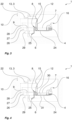
- Fig. 2 shows a schematic view of a steam-generator 1 with the inlet-valve 12 closed.
- a water-source 3 for example a water-tank 13 (here purely optionally with a pull-out drawer 22), is shown at the top left.
- an active inlet-valve 12 is sketched, which is arranged below in the earth-gravity-field 10 and which, as said, is shown in the closed state and thus the water from the water-source 3 is prevented from flowing into the distributor 24.
- the inlet-connection 15 opens into the distributor 24, which runs to the right as shown (i.e., uphill) to the steam-generator 4 and the precipitator 5.
- the water-outlet 6, which in this embodiment opens into the cavity 17, is connected to the siphon 8. It should also be noted that a steam-delivery-port 16 is provided in the earth-gravity-field 10 above the precipitator 5 towards the cavity 17.
- a reference-level 25 is defined at the lowest point of the distributor 24, from which the target-height 26 i.e., the vertical distance, to the nominal-fill-level 7 is defined.
- the siphon-height 27 i.e., the vertical distance, to the siphon-level 9 is also defined from the reference-level 25.
- the siphon-height 27 is greater than the target-height 26.
- the valve-height 28 i.e., the vertical distance, between the reference-level 25 and the active inlet-valve 12 is defined, as well as the minimum tankheight i.e., the vertical distance, between the reference-level 25 and the deepest point of the water-source 3 is defined.
- the outlet-depth 29 i.e., the vertical distance between the reference-level 25 and the water-outlet 6, on the other hand, is arranged in the earth-gravity-field 10 below the reference-level 25.
- a nominal-fill-level 7 is set below the siphon-level 9 of the siphon 8, set up using appropriate control of the active inlet-valve 12 and otherwise using gravity alone.
- the water remains in the system section with the steam-generator 4 and the precipitator 5, as well as the steam-delivery-port 16.
- a time sequence 18 of a cleaning process is shown, whereby at least the water in the distributor 24, the precipitator 5 and the steam-generator 4 is then here a cleaning solution.
- the cleaning solution is kept in the state shown for a predetermined time to dissolve deposits, for example, among other things, limescale, and is heated if necessary (preferably using the steam-generator 4).
- Fig. 3 shows the schematic view of the steam-generating-device 1 according to Fig. 2 with the inlet-valve 12 open.
- the water flows here through the active (open) inlet-valve 12 into the distributor 24 and raises the fill-level above the nominal-fill-level 7 and also above the siphon-level 9.
- the water thus flows out of the water-outlet 6. This is desirable, for example, for cleaning or rinsing. It should be noted that, apart from the active inlet-valve 12, no other active component, especially no pump, is necessary for this either.
- Fig. 4 shows a schematic view of the steam-generating-device 1 according to Fig. 2 and Fig. 3 without water supply from the water-source 3.
- the water-source 3 is empty.
- the active inlet-valve 12 is closed again.
- the current fill-level 30 in the steam-generator 4 and the precipitator 5 is now again below the siphon-level 9 and even below the nominal-fill-level 7. But there is still a height-difference 31 between the current fill-level 30 and the water-outlet 6, so that there is a water column with sufficient pressure to overcome the threshold of the siphon-level 9 until all or almost all of the water has flowed out of the distributor 24. No active component is required for this either, not even the active inlet-valve 12.
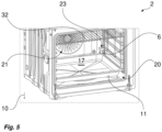
- Fig. 5 shows a perspective front view of a domestic oven 2.
- the cavity 17 is visible through the front-opening 20, in which a suspended grid 32 can be seen.
- a fan can be seen, which is simplified here as part of a heating-device 21, whereby (independently of the fan) a gas burner and/or an electric heating coil is usually arranged in the bottom wall (below) and/or in the top wall (above) of the cavity 17.
- the water-outlet 6 can also be seen here, which opens laterally into the cavity 17, whereby a basin is inserted here (for example for a cleaning process) as a descaling-receptacle 11 in the cavity 17.
- a (purely optional) wet-bulb-sensor-device 23 is shown here, by means of which the supply of steam (the steam-delivery-port 16 is concealed here) and thus the steam-generator 4 is preferably controlled.
- the steam-generating-device proposed here enables particularly simple and cost-effective operation.
Landscapes
- Engineering & Computer Science (AREA)
- Chemical & Material Sciences (AREA)
- Combustion & Propulsion (AREA)
- Mechanical Engineering (AREA)
- General Engineering & Computer Science (AREA)
- Cookers (AREA)
- Devices For Medical Bathing And Washing (AREA)
Abstract
- a water-source (3);
- a steam-generator (4) arranged to be fed with water from the water-source (3) and arranged to generate steam;
- a precipitator (5) for condensed water from the steam of the steam-generator (4);
- a water-outlet (6) for discharging water from the precipitator (5) and/or the steam generator (4),
the steam-generator (4) and the precipitator (5) having a nominal-fill-level (7) for liquid water during operation. A siphon (8) with a fixed siphon-level (9) is also provided upstream of the water-outlet (6), the siphon-level (9) being arranged at least at or above the nominal-fill-level (7) of the precipitator (5) and the steam-generator (4) when a domestic oven (2) is installed in the earth-gravity-field (10).
Description
- The invention relates to a steam-generating-device for a domestic oven, and to a domestic oven comprising such a steam-generating-device.
- A steam cooker function is desired for many domestic ovens. For this purpose, a steam-generating-device with a steam-generator is integrated into the domestic oven or connected to it externally. The steam-generating-device is supplied with water from a water-tank or from a standard household wall connection (with a standard line pressure). Currently, known steam-generating-devices are very costly because a complex system is required to provide the necessary pressure gradient depending on the use case. While the main use case is to supply the steam-generating-device with water, it is necessary to clean the steam-generating-device due to limescale and other (adhering) solids. Therefore, cleaning or decalcification requires different pressure gradients in the steam-generating-device.
- On this basis, the present invention is based on the task of at least partially overcoming the disadvantages known from the prior art. The features according to the invention result from the independent claims, for which advantageous embodiments are shown in the dependent claims. The features of the claims can be combined in any technically sensible manner, whereby the explanations from the following description as well as features from the figures, which comprise supplementary embodiments of the invention, can also be used for this purpose.
- The invention relates to a steam-generating-device for a domestic oven, comprising at least the following components:
- a water-source;
- a steam-generator arranged to be fed with water from the water-source and arranged to generate steam;
- a precipitator for condensed water from the steam of the steam-generator;
- a water-outlet for discharging water from the precipitator and/or the steam generator,
- The steam-generating-device is characterised in particular by the fact that a siphon with a fixed siphon-level is also provided upstream of the water-outlet, the siphon-level being arranged at least at or above the nominal-fill-level of the precipitator and the steam-generator when a domestic oven is installed in the earth-gravity-field.
- The spatial directions used herein refer to the intended use in operation, the orientation to the earth-gravity-field, if of anything being referred to as the top, and a user side or front side, i.e. a side to which the user has intended access (for example via a door to a domestic oven); if of anything being referred to as the front, the rear side being the usually inaccessible side opposite the user side (often intended for at least one wall-connection and/or facing a wall). In some applications, for example in the case of stovetops or domestic ovens with a stovetop, a (possibly further) user side is the top side. The sides or lateral elements are arranged between front and rear and extending along the earth-gravity-field, often referred to as left or right, but thus not arranged below or above between front and rear. It should be noted that often a connection is not or not only provided at the rear, but also alternatively or additionally at the sides, bottom and/or top.
- Unless explicitly stated to the contrary, ordinal numbers used in the preceding and following descriptions are for the purpose of clear distinction only and do not reflect any order or ranking of the designated components. An ordinal number greater than one does not imply that another such component must necessarily be present.
- The steam-generating-device proposed here is set up as explained at the beginning. In one embodiment, the water-source is a water-tank, in another or additionally a connection to a (household) wall connection. The steam-generator is set up for evaporating, for example using heating, provided water. The water is provided from the water-source.
- The precipitator is designed to retain condensed water from the steam (-liquid-mixture) generated by the steam-generator. For this purpose, the precipitator has labyrinth-like walls in an installed domestic oven in the earth-gravity-field in relation to the effect of gravity on the vapour-like water, to which liquid water or water droplets can adhere and (at least collectively) drip off. Furthermore, the precipitator comprises a collecting basin for liquid water, preferably in the earth-gravity-field below a steam-delivery-port to a cavity of a domestic oven, into which water in a state as purely as possible being vapourised is to be fed. At the same time, the collection basin is preferably arranged in such a way that the water cannot be fed exclusively to the water-outlet, but can also (or primarily) be fed directly (i.e. without further treatment and/or external or additional energy supply) back to the steam-generator, preferably with a basin outlet near a feed inlet-port of the steam-generator. Alternatively or additionally, an outlet-port is formed towards a water-outlet.
- The steam-generator and the precipitator have a common nominal-fill-level, from which, in use in the earth-gravity-field, a common horizontal line is preferably formed transverse to the (vertical) gravity. from this nominal-fill-level, the steam emerges or rises from the steam-generator. The nominal-fill-level is therefore determined by the corresponding requirements for the most energy-efficient operation of the steam-generator.
- The water-outlet is arranged to discharge water, for example to maintain said nominal-fill-level. The water-outlet is arranged in a flow direction within the steam-generator at the end. For example, all the above-mentioned components of the steam-generating-device are arranged in the earth-gravity-field above the water-outlet, so that water flows towards the water-outlet with a downward gradient during operation of the steam-generator.
- It is now proposed that a siphon is provided which is connected upstream of the water-outlet in the direction of flow within the steam-generating-device. Such a siphon has at least one threshold that must be overcome by the outflowing water against the force of gravity during operation. This defines a siphon-level. In one embodiment, the siphon is a reverse-U-shaped conduct with the siphon-level being defined by the bottom of the U-shape, which is the highest point of that conduct. If the siphon-level is not exceeded by the water in the steam-generator and precipitator, i.e. the current fill-level, the water cannot flow out via the water-outlet. Only when the siphon-level is exceeded can at least part of the water flow out via the water-outlet.
- By arranging the siphon-level (in an installed domestic oven in the earth-gravity-field) at or above the nominal-fill-level, the nominal-fill-level can be maintained without further means, especially without an active control via, for example, an active outlet valve or an active pump. At the same time, however, in the event of cleaning (for example, the descaling mentioned at the beginning), an outflow of (cleaning) fluid is possible, also passively at least with regard to the water-outlet. In one embodiment, a cleaning liquid is passively expelled from the steam-generating-device without the need for rinsing as soon as the siphon-level has been overcome, whereby all or almost all of the liquid is then drawn out by itself overcoming the siphon-level (which is higher at least towards the end) as a result of the water column pressure in relation to the water-outlet, which is always lower, although the threshold is connected upstream of the water-outlet.
- In one embodiment, the nominal-fill-level is actively controlled, for example using a flow rate and/or evaporation rate in the direction of flow upstream of the siphon. In one embodiment, water overflow is accepted and the nominal-fill-level is reliably adjusted passively using the effect of the siphon-level. In one embodiment, the liquid sensor or temperature sensor of the steam-generator is used to detect a need for water i.e., to conclude that the fill-level has dropped below the nominal-fill-level. It should be noted that in a preferred embodiment, the nominal-fill-level is a range that oscillates around a control value or above or below the control value, but by an amount acceptable for the use.
- It is further proposed in an advantageous embodiment of the steam-generating-device that the water-outlet is connectable or connected to a descaling-receptacle.
- In this embodiment, the water-outlet is connected to a descaling-receptacle, for example a container that is integrated permanently or during normal operation of the steam-generator or a basin that is inserted or positioned when required. This makes it easy to collect the water (e.g. in the event of overfilling of the steam-generating-device or an internal fault) and/or a cleaning liquid. In an alternative embodiment, the water-outlet is connected to a standard household wall connection, in this case correspondingly for waste water (preferably permanently installed).
- It is further proposed in an advantageous embodiment of the steam-generating-device that said water-source comprises an active inlet-valve, said active inlet-valve being located in an installed domestic oven in the earth-gravity-field above the nominal-fill-level of the precipitator and the steam-generator.
- Using the active inlet-valve, the nominal-fill-level (or other desired fill-level) is easily and safely adjustable under the assumed or electronically verified condition that sufficient water is provided by the water-source. In an advantageous embodiment, the active inlet-valve is the sole admission control for water to the steam-generator. The active inlet-valve is transferable to at least two positions, namely a (fully) open position and a (fully) closed position. Alternatively, the active inlet-valve is set up to meter the flow i.e., different flow cross-sections can be (actively) set in a discrete or continuously adjustable manner. The inlet-valve is preferably electronically controllable, for example with an electric actuator.
- It is further proposed in an advantageous embodiment of the steam-generating-device that the water-source comprises a water-tank which, in an installed domestic oven, is arranged in the earth-gravity-field above the nominal-fill-level of the precipitator and the steam-generator, wherein the water passes from the water tank to the steam generator solely due to gravitational force acting on the water itself.
- In this embodiment, a water-tank is set up to provide water for the steam-generator. In one embodiment, the water-tank can be supplied with water directly from a standard household wall connection. In one embodiment, a household wall connection is connected in addition to the water-tank for providing water. In a preferred embodiment, the water-tank is manually refillable by a user and provides a sufficient volume of water for a predetermined period of use. Preferably, the volume of water is such that a complete cleaning process (according to a physical necessity and/or a software-specified one) can be carried out with sufficient water and/or cleaning fluid without refilling in the meantime. In an advantageous embodiment, the (target) volume of the water-tank is just set up so that it is emptied after a complete cleaning process.
- It is further proposed in an advantageous embodiment of the steam-generating-device that the water-tank is directly connected to the water-outlet via an overflow-connection.
- It is proposed that the water-tank has an overflow-connection so that the water-tank cannot be overfilled and thus an overflow into other areas, for example with corrosion-prone and/or electronic or electrically conductive elements, is prevented. According to the above suggestion, the overflow-connection is directly connected to the water-outlet, so that in one embodiment the overflowing water drains into a permanently installed container or basin provided for this purpose or a (sewage) wall connection. Alternatively, a basinlike depression is formed in the cavity of the domestic oven, for example, or an overflow is noticeable to a user because of the (non-corrosive) steam-resistant material in the cavity, and the water that has overflowed there can be removed, for example, collected, without damage and with little effort. Alternatively, the overflowed water can also remain there and be evaporated during the operation of the domestic oven when it is next heated (for example, when preparing comestible goods).
- The overflow-connection is directly connected to the water-outlet in such a way that it is downstream of the siphon in the direction of flow (of the water behind the inlet-valve) i.e., it does not have to overcome the siphon-level in order to flow out through the water-outlet. This means that the setting, preferably regulation, of the nominal-fill-level is not affected by overflowing water from the water-tank.
- It should be noted that herein an outlet, overflow-connection and inlet-connection and similar designations defines pipes or hoses, preferably each a single pipe or hose, as the case may be, comprising (for example using welds or sleeves) sections connected in series. Such subsections are also interrupted, for example, by a component such as the inlet-connection being interrupted (or split into two parts) by the inlet-valve.
- It is further proposed in an advantageous embodiment of the steam-generating-device that an inlet-valve according to an embodiment of above description is arranged in an inlet-connection for supplying water to the steam-generator and is arranged in an installed domestic oven in the earth-gravity-field below the water-tank.
- In this embodiment, the active inlet-valve is arranged in the earth-gravity-field below the water-tank and thus, when the water-tank is sufficiently filled, a sufficient water column pressure is applied to the active inlet-valve, which is preferably constant within a narrow range with the aid of an appropriate design of the water-tank. A water column pressure that is considered sufficient here enables the nominal-fill-level to be set (or regulated) using only opening and closing the active inlet-valve. It is therefore not necessary to provide a pump or to compulsorily provide the water using a wall connection with an appropriate household water pressure as water-source. The only necessary active (i.e., performing an active movement) component of the steam-generating-device in this embodiment is the active inlet-valve.
- It should be noted that in an advantageous embodiment, a plurality of sensors are used, but these only require a fraction of the (electrical) energy that a pump requires. It should also be noted that the active inlet-valve also requires significantly less energy and is less complicated and thus more cost-effective to implement than a shut-off valve, as is necessary for a wall connection as a water-source, because the water column pressure of the water-tank is lower than a normal household water pressure for which such a shut-off valve must be designed.
- It is further proposed in an advantageous embodiment of the steam-generating-device that the precipitator comprises a steam-delivery-port to a cavity of a domestic oven, the steam-delivery-port being simultaneously connected via a bridge-connection to an inlet-connection between the water-source and the precipitator and the steam-generator, and to the siphon.
- In this embodiment, a steam-delivery-port for the cavity is part of the precipitator. In one embodiment, the precipitator is a coherent box, for example with a pot and a lid or injection moulded in one piece. In one embodiment, the precipitator is formed from a conduit system. In an alternative embodiment, the precipitator is arranged upstream of the steam-delivery-port in the flow direction of the steam generated by the steam-generator.
- It is further proposed here that (in combination with one of the aforementioned embodiments of the steam-delivery-port) a bridge-connection is further provided. This bridge-connection is provided for discharging condensed water, whereby the condensed water is recirculated using the bridge-connection. The bridge-connection is in fact connected between the water-source and the precipitator and the steam-generator, as well as the siphon, and is thus arranged upstream of the precipitator and the steam-generator, as well as the siphon, in the direction of flow of the condensed water. In one embodiment, the condensed water is recirculated without further control and/or without measurement.
- It is further proposed in an advantageous embodiment of the steam-generating-device that the bridge-connection of the steam-delivery-port in an installed domestic oven being in the earth-gravity-field below an inlet-valve according to an embodiment of above description is connected to an inlet-connection between the water-source and the precipitator and the steam-generator, as well as the siphon.
- Here it is proposed that the bridge-connection is connected in the earth-gravity-field below the active inlet-valve as described above. Thus, the condensed water is kept in the section that is fed with water from the water-source in a controlled manner using the active inlet-valve. At the same time, the desired nominal-fill-level is maintained using the siphon-level, preferably as described above without any further control means besides the active inlet-valve.
- It is further proposed in an advantageous embodiment of the steam-generating-device that the bridge-connection of the steam-delivery-port has a point which, in an installed domestic oven, is higher in the earth-gravity-field than the steam-delivery-port.
- Using this raised point, the bridge-connection is also designed in a siphon-like manner, whereby firstly, as a result of the rise of the bridge-connection starting from the steam-delivery-port, an inflow of steam into the bridge-connection is limited and secondly, a proportion already present as liquid water (condensed water) flows directly back into the precipitator. Water that gets behind the highest point of the bridge-connection, for example from the steam form only condenses there, is then returned to the system as described above. The bridge-connection formed in this way is protected from impairment by deposits, such as limescale, over a targeted service life of the steam-generating-device and does not necessarily have to be cleaned during a cleaning process.
- According to a further aspect, a domestic oven is proposed comprising at least the following components:
- a cavity having a front-opening for receiving comestible goods to be heated;
- a heating-device for raising the temperature within the cavity; and
- a steam-generating-device according to an above described embodiment, the steam-generating-device being connected to the cavity for releasing steam using a steam-delivery-port.
- The domestic oven is, for example, a steam cooker, a baking oven and/or a microwave oven, whereby preferably a steam cooking function is integrated into both of the latter using the steam-generating-device in accordance with an embodiment described above. In operation, a front-opening closable by a door is provided at the front and/or at the top, via which the cavity of the domestic oven is accessible to a user, wherein a climate can be set within the cavity i.e., usually an increased temperature and/or increased humidity compared to the (kitchen) environment. For this purpose, the cavity and/or the door is preferably thermally insulated from the environment. It should be noted that the domestic oven proposed here is designed with an integrated or without i.e., separate, door. A heating-device is provided for heating the space in the cavity. For generating steam or increased humidity, the steam-generating-device is provided. Furthermore, the domestic oven comprises a water-source, whereby this is formed in one embodiment as a water-tank or alternatively by a connection (for example together with a pipe) for a wall connection customary in households.
- A domestic oven according to one embodiment includes an oven body, a (cooking) cavity inside the oven body, a control panel with a water (pull-out) drawer for loading water, a steam-generating device located in a compartment external to the cavity.
- In one embodiment, the domestic oven comprises a water-tank, an (inlet) valve being fluidically connected to the water-tank at the valve inlet, and connected to a steam-generator (circuit) at the valve outlet, a steam-generator being fluidically connected to the valve, wherein the steam-generator delivers steam to the cavity, a siphon connected on one end to the lowest part in the steam-generator circuit and behind the valve (can be the steam-generator), and on the other end to an outlet that in one embodiment leads into the cavity or to the front face of the oven. Further, the end of the siphon being connected to the cavity is located at an elevation below the lowest part of the steam-generator circuit in the direction of gravity, and the working water level of the steam-generator being lower (in a gravity direction) than the highest portion of the siphon.
- The above layout of components allows the steam-generating-device to work normally when the water level is kept at the nominal level (or lower), but also enables a method of draining the steam circuit.
- This water draining method implies that the water valve opens for the necessary amount of time to let a water portion to fill up the steam generating circuit, at least up to the highest portion of the siphon, so then the siphon is activated and all the water contained in the steam system will move to the bridge-connection outlet thanks to the principle of the siphon.
- When the user selects a steam cooking function, or a cooking function that requires steam, the steam-generating-device will be activated. When the steam generation is active, the steam-generator is powered and therefore it is evaporating water. Steam then is injected inside the cooking cavity in order to enhance cooking performance.
- During such working condition, in order to guarantee the maximum efficiency, the steam-generator will need a stable water level. Such (nominal) level is conveniently located below the highest portion of the siphon, in order to prevent accidental spillage off water into the siphon.
- While the steam-generator is evaporating water, the water level obviously decreases. In order to maintain the water level inside the steam-generator approximately constant, the water valve will open or a pump will provide water (pressure) to allow the necessary amount of water to replenish the system, and reach back the nominal water level.
- This water feeding system can be controlled according to a closed loop, by using the signal from a water level sensor located in the steam generation circuit, approximately at the height of the nominal-fill-level. A possible control logic for such system can be the following:
- When the water level goes below the target-height due to evaporation, the sensor will detect it. The oven controls are receiving this signal, commanding the opening of the valve.
- The valve will stay open until the level sensor detects that the water level is back at the target-height. Once target-height is reached, the valve will close.
- Example use case - system drain/rinse:
- 1. The user puts a tray below the water-outlet exit in the cavity (or a pitcher below a water exit in the front frame);
- 2. The user fills the water-tank with fresh water up to the maximum level. Then, the user presses "start drain" in a user interface of the domestic oven;
- 3. The inlet-valve will let a first or the entire amount of water pass through. Eventually, the water will reach the highest portion of the siphon, activating the siphon effect;
- 4. The inlet-valve is left open for the necessary amount of time for emptying the whole content of the tank in the steam generation system;
- 5. All the liquid in the system is transferred to the tray (or pitcher) put by the user at
step 1; and - 6. This operation can be repeated in order to get a more effective rinse.
- Example use cases - descaling:
- 1. The user puts a tray below the water-outlet in the cavity (or a pitcher below a water exit in the front frame);
- 2. The user fills the water-tank with fresh water mixed with a descaling agent up to the maximum level. Then, the user presses "start descaling" in a user interface of the domestic oven;
- 3. The inlet-valve will let a first or the entire amount of the (descaling) liquid to pass through until the water level sensor detects that the circuit is full;
- 4. The liquid is left in the circuit in order dissolve limescale. The fluid can also be heated up to boost the descaling;
- 5. After a certain amount of time, the valve is opened to let the remaining fluid or a fluid (without descaling agent) freshly filled into the water-tank by the user or from a different tank to flow into the system. This will trigger the siphon effect;
- 6. All the liquid in the system is transferred to the tray or pitcher put by the user;
- 7. In case in
step 5, the remaining fluid contains descaling agent, a system drain or rinse with fresh water is performed as describe above, wherein preferably the user does not have to start the program by pressing "start drain" and/or only acknowledge that the water-tank is refilled with (clean) water. - It is further proposed in an advantageous embodiment of the domestic oven that a water-tank according to an embodiment of above description is arranged in the installed domestic oven in the earth-gravity-field above the cavity.
- In this embodiment, a usually available installation space can be utilised at the same time, which is spanned vertically above the cavity by electronic components and/or the installation space of a hotplate arranged above it. Furthermore, the water-tank is thus arranged at a height that is easily accessible for a user in the usual arrangement of a domestic oven in a kitchen.
- It is further proposed in an advantageous embodiment of the domestic oven that the water-tank can be filled from the front with respect to the front-opening of the cavity,
preferably using a pull-out drawer. - A water-tank that can be filled from the front is particularly easy for a user to access. A pull-out drawer enables the ergonomic pouring of water or the use of any vessels for pouring water into the water-tank.
- It is further proposed in an advantageous embodiment of the domestic oven that in the installed domestic oven, with respect to the front-opening, at least one of the following components is located behind the cavity:
- the steam-generator;
- the precipitator;
- the siphon;
- an inlet-valve according to an embodiment as described above; and
- a steam-delivery-port according to an embodiment as described above.
- An embodiment with all the components mentioned being arranged behind the cavity is particularly space-saving in a normally available installation space, in which the installation depth of the cavity and other components of the domestic oven is not fully utilised. In an alternative embodiment, all or some of said components are arranged laterally, below or above the cavity. In yet another alternative embodiment, said components or the entire steam-generating-device are housed in a separate installation space from the installation space provided for the domestic oven.
- It is further proposed in an advantageous embodiment of the domestic oven that the heating-device comprises at least one of the following heat sources:
- an electric heating coil;
- a gas burner; and
- a magnetron.
- In one embodiment, a fan is also provided to distribute the generated heat. In one embodiment, two separate means are provided, for example a gas burner and an electric heating coil, or for example at least one electric heating coil and a magnetron (for generating so-called microwaves). In one embodiment, a means for generating top heat and a separate means for generating bottom heat are comprised by the heating-device.
- It is further proposed in an advantageous embodiment of the domestic oven that a wet-bulb-sensor-device is arranged in the cavity,
wherein releasing steam via the steam-delivery-port into the cavity is controlled using the wet-bulb-sensor-device. - The wet-bulb-sensor-device is set up to detect the wet bulb temperature, whereby a basin or its opening (oriented upwards during operation) and the temperature sensor are arranged in the cavity for this purpose. A temperature detected using the wet-bulb-sensor-device can be used as an input value, preferably in addition to a dry temperature detection, for the temperature control device or integrated into a corresponding control loop. The temperature and/or the relative humidity as a setpoint is specified by a user directly or indirectly (for example via a programme). Depending on the desired water vapour saturation in the cavity, steam is generated by the steam-generator on the basis of the measured values of the wet-bulb-sensor-device. The wet-bulb-sensor-device itself is to be supplied with water, whereby this is preferably made available using the said water-source, particularly preferably from the water-tank of the wet-bulb-sensor-device arranged above the cavity (in use in the earth-gravity-field).
- The invention described above is explained in detail below against the relevant technical background with reference to the accompanying drawings, which show preferred embodiments. The invention is in no way limited by the purely schematic drawings, it being noted that the drawings are not dimensionally accurate and are not suitable for defining dimensional relationships. It is illustrated in
- Fig. 1:
- a perspective rear view of a domestic oven;
- Fig. 2:
- a schematic view of a steam-generating-device with the inlet-valve closed;
- Fig. 3:
- the schematic view of the steam-generating-device according to
Fig. 2 with the inlet-valve open; - Fig. 4:
- the schematic view of the steam-generating-device according to
Fig. 2 andFig. 3 without water supply from the water-source; and - Fig. 5:
- a perspective front view of a domestic oven.
-
Fig. 1 shows adomestic oven 2 in a perspective rear view. Here you can see the modification around thecavity 17. The front-opening 20 is covered here. In the embodiment shown, apart from the water-source 3, which is designed here as a water-tank 13, all other components of the steam-generating-device 1 are arranged at the rear side of thedomestic oven 2. An overflow-connection 14 can be seen on the far left of the illustration, using which a maximum filling level of the water-tank 13 is defined. The overflow-connection 14 is connected to a water-outlet 6, which opens into thecavity 17, for example as shown inFig. 5 . An inlet-connection 15 can be seen on the water-tank 13 below the connection of the overflow-connection 14, which in the further course runs to the right of the overflow-connection 14 as shown. - Within the inlet-
connection 15 an active inlet-valve 12 can be seen, which is arranged in the earth-gravity-field 10 below the water-tank 13. The inlet-connection 15 (behind the inlet-valve 12) opens into adistributor 24, which in the illustration is inclined to the left, i.e. towards the water-outlet 6, at a small angle (for example 5° [five degrees of 360°]) to 10° to a ground plane (to which the earth-gravity-field 10 is normally aligned). As shown, a steam-generator 4 is connected to the right of the course of thedistributor 24 i.e., against a flow direction with no water column in the inlet-connection 15. the steam-generator 4 has a bend upwards and opens into aprecipitator 5. Theprecipitator 5 is here in the form of a continuous box with a labyrinth-like wall, so that the steam must flow from a highest point in theprecipitator 5 to a lower point in order to reach the steam-delivery-port 16, which is here arranged in a conduit which is formed separately from the continuous box of theprecipitator 5 and merges (in the direction away from the precipitator 5) behind the steam-delivery-port 16 into a bridge-connection 18. The steam-delivery-port 16 is connected from the rear-outside to thecavity 17 for discharging the generated steam into thecavity 17. The saidoutlet 18 here has a (highest)point 19, which is higher in the earth-gravity-field 10 than the steam-delivery-port 16. Behind thishighest point 19, theoutlet 18 opens into the inlet-connection 15, in this case below the inlet-valve 12. Theprecipitator 5 is also connected to thedistributor 24 immediately before the steam-generator 4 enters. In the direction of flow downstream of the inlet-connection 15, thedistributor 24 opens into a siphon 8, which is concealed here (compareFig. 2 to Fig. 4 ). -
Fig. 2 shows a schematic view of a steam-generator 1 with the inlet-valve 12 closed. A water-source 3, for example a water-tank 13 (here purely optionally with a pull-out drawer 22), is shown at the top left. Above the inlet-connection 15, an active inlet-valve 12 is sketched, which is arranged below in the earth-gravity-field 10 and which, as said, is shown in the closed state and thus the water from the water-source 3 is prevented from flowing into thedistributor 24. Behind i.e., below the active inlet-valve 12, the inlet-connection 15 opens into thedistributor 24, which runs to the right as shown (i.e., uphill) to the steam-generator 4 and theprecipitator 5. In the earth-gravity-field 10 below a lowest point of the steam-generating-device 1, i.e. in this embodiment of thedistributor 24, the water-outlet 6, which in this embodiment opens into thecavity 17, is connected to the siphon 8. It should also be noted that a steam-delivery-port 16 is provided in the earth-gravity-field 10 above theprecipitator 5 towards thecavity 17. - For traceability, a reference-
level 25 is defined at the lowest point of thedistributor 24, from which the target-height 26 i.e., the vertical distance, to the nominal-fill-level 7 is defined. The siphon-height 27 i.e., the vertical distance, to the siphon-level 9 is also defined from the reference-level 25. The siphon-height 27 is greater than the target-height 26. Furthermore, the valve-height 28 i.e., the vertical distance, between the reference-level 25 and the active inlet-valve 12 is defined, as well as the minimum tankheight i.e., the vertical distance, between the reference-level 25 and the deepest point of the water-source 3 is defined. These mentioned heights are located in the earth-gravity-field 10 above the reference-level 25. The outlet-depth 29 i.e., the vertical distance between the reference-level 25 and the water-outlet 6, on the other hand, is arranged in the earth-gravity-field 10 below the reference-level 25. - Here it can be seen that a nominal-fill-
level 7 is set below the siphon-level 9 of the siphon 8, set up using appropriate control of the active inlet-valve 12 and otherwise using gravity alone. Thus, the water remains in the system section with the steam-generator 4 and theprecipitator 5, as well as the steam-delivery-port 16. For example, inFig. 2 to Fig. 4 atime sequence 18 of a cleaning process is shown, whereby at least the water in thedistributor 24, theprecipitator 5 and the steam-generator 4 is then here a cleaning solution. Here, the cleaning solution is kept in the state shown for a predetermined time to dissolve deposits, for example, among other things, limescale, and is heated if necessary (preferably using the steam-generator 4). -
Fig. 3 shows the schematic view of the steam-generating-device 1 according toFig. 2 with the inlet-valve 12 open. The water flows here through the active (open) inlet-valve 12 into thedistributor 24 and raises the fill-level above the nominal-fill-level 7 and also above the siphon-level 9. The water thus flows out of the water-outlet 6. This is desirable, for example, for cleaning or rinsing. It should be noted that, apart from the active inlet-valve 12, no other active component, especially no pump, is necessary for this either. -
Fig. 4 shows a schematic view of the steam-generating-device 1 according toFig. 2 andFig. 3 without water supply from the water-source 3. Here it is shown that the water-source 3 is empty. Alternatively or additionally, the active inlet-valve 12 is closed again. The current fill-level 30 in the steam-generator 4 and theprecipitator 5 is now again below the siphon-level 9 and even below the nominal-fill-level 7. But there is still a height-difference 31 between the current fill-level 30 and the water-outlet 6, so that there is a water column with sufficient pressure to overcome the threshold of the siphon-level 9 until all or almost all of the water has flowed out of thedistributor 24. No active component is required for this either, not even the active inlet-valve 12. If some of the water or a (food-incompatible or non-taste-neutral) cleaning solution remains in thedistributor 24, such a flushing process must be repeated at least once (but then with water without cleaning agent), as shown in the chronological sequence ofFig. 2 to Fig. 4 . -
Fig. 5 shows a perspective front view of adomestic oven 2. Thecavity 17 is visible through the front-opening 20, in which a suspendedgrid 32 can be seen. On the rear wall of the cavity 17 a fan can be seen, which is simplified here as part of a heating-device 21, whereby (independently of the fan) a gas burner and/or an electric heating coil is usually arranged in the bottom wall (below) and/or in the top wall (above) of thecavity 17. - The water-
outlet 6 can also be seen here, which opens laterally into thecavity 17, whereby a basin is inserted here (for example for a cleaning process) as a descaling-receptacle 11 in thecavity 17. Above the water-outlet 6, a (purely optional) wet-bulb-sensor-device 23 is shown here, by means of which the supply of steam (the steam-delivery-port 16 is concealed here) and thus the steam-generator 4 is preferably controlled. - The steam-generating-device proposed here enables particularly simple and cost-effective operation.
-
- 1
- steam-generating-device
- 2
- domestic oven
- 3
- water-source
- 4
- steam-generator
- 5
- precipitator
- 6
- water-outlet
- 7
- nominal-fill-level
- 8
- siphon
- 9
- siphon-level
- 10
- earth-gravity-field
- 11
- descaling-receptacle
- 12
- active inlet-valve
- 13
- water-tank
- 14
- overflow-connection
- 15
- inlet-connection
- 16
- steam-delivery-port
- 17
- cavity
- 18
- bridge-connection
- 19
- highest spot
- 20
- front-opening
- 21
- heating-device
- 22
- pull-out drawer
- 23
- wet-bulb-sensor-device
- 24
- distributor
- 25
- reference-level
- 26
- target-height
- 27
- siphon-height
- 28
- valve-height
- 29
- outlet-depth
- 30
- current fill-level
- 31
- height-difference
- 32
- furnace-grate
Claims (15)
- A steam-generating-device (1) for a domestic oven (2), comprising at least the following components:- a water-source (3);- a steam-generator (4) arranged to be fed with water from the water-source (3) and arranged to generate steam;- a precipitator (5) for condensed water from the steam of the steam-generator (4);- a water-outlet (6) for discharging water from the precipitator (5) and/or the steam generator (4),the steam-generator (4) and the precipitator (5) having a nominal-fill-level (7) for liquid water during operation, characterised in that,a siphon (8) with a fixed siphon-level (9) is also provided upstream of the water-outlet (6), the siphon-level (9) being arranged at least at or above the nominal-fill-level (7) of the precipitator (5) and the steam-generator (4) when a domestic oven (2) is installed in the earth-gravity-field (10).
- The steam-generating-device (1) according to claim 1,
wherein
the water-outlet (6) is connectable or connected to a descaling-receptacle (11). - The steam-generating-device (1) according to claim 1 or claim 2, wherein
said water-source (3) comprises an active inlet-valve (12), said active inlet-valve (12) being located in an installed domestic oven (2) in the earth-gravity-field (10) above the nominal-fill-level (7) of the precipitator (5) and the steam-generator (4). - The steam-generating-device (1) according to one of the preceding claims, wherein the water-source (3) comprises a water-tank (13) which, in an installed domestic oven (2), is arranged in the earth-gravity-field (10) above the nominal-fill-level (7) of the precipitator (5) and the steam-generator (4),
wherein the water passes from the water-tank (13) to the steam-generator (4) solely due to gravitational force acting on the water itself. - The steam-generating-device (1) according to claim 4,
wherein
the water-tank (13) is directly connected to the water-outlet (6) via an overflow-connection (14). - The steam-generating-device (1) according to claim 4 or claim 5, wherein
an inlet-valve (12) according to claim 3 is arranged in an inlet-connection (15) for supplying water to the steam-generator (4) and is arranged in an installed domestic oven (2) in the earth-gravity-field (10) below the water-tank (13). - The steam-generating-device (1) according to any one of the preceding claims, wherein
the precipitator (5) comprises a steam- delivery-port (16) to a cavity (17) of a domestic oven (2), the steam-delivery-port (16) being simultaneously connected via a bridge-connection (18) to an inlet-connection (15) between the water-source (3) and the precipitator (5) and the steam-generator (4), and to the siphon (8). - The steam-generating-device (1) according to claim 7,
wherein
the bridge-connection (18) of the steam-delivery-port (16) in an installed domestic oven (2) being in the earth-gravity-field (10) below an inlet-valve (12) according to claim 3 is connected to an inlet-connection (15) between the water-source (3) and the precipitator (5) and the steam-generator (4), as well as the siphon (8).? - The steam-generating-device (1) according to claim 7 or claim 8, wherein
the bridge-connection (18) of the steam-delivery-port (16) has a point (19) which, in an installed domestic oven (2), is higher in the earth-gravity-field than the steam-delivery-port (16). - A domestic oven (2) comprising at least the following components:- a cavity (17) having a front-opening (20) for receiving comestible goods to be heated;- a heating-device (21) for raising the temperature within the cavity (17); and- a steam-generating-device (1) according to any one of the preceding claims, the steam-generating-device (1) being connected to the cavity (17) for releasing steam using a steam-delivery-port (16).
- The domestic oven (2) according to claim 10, wherein
a water-tank (13) according to claim 4 is arranged in the installed domestic oven (2) in the earth-gravity-field (10) above the cavity (17). - The domestic oven (2) according to claim 10 or claim 11,
wherein
the water-tank (13) can be filled from the front with respect to the front-opening (20) of the cavity (17), preferably using a pull-out drawer (22). - The domestic oven (2) according to any one of claim 10 to claim 12, wherein in the installed domestic oven (2), with respect to the front-opening (20), at least one of the following components is located behind the cavity (17):- the steam-generator (4);- the precipitator (5);- the siphon (8);- an inlet-valve (12) according to claim 3 or one of claim 6 to claim 9; and- a steam-delivery-port (16) according to one of claim 7 to claim 9.
- The domestic oven (2) according to any one of claim 10 to claim 13, wherein the heating-device (21) comprises at least one of the following heat sources:- an electric heating coil;- a gas burner; and- a magnetron.
- The domestic oven (2) according to any one of claim 10 to claim 14, whereina wet-bulb-sensor-device (23) is arranged in the cavity (17),wherein releasing steam via the steam-delivery-port (16) into the cavity (17) is controlled using the wet-bulb-sensor-device (23).
Priority Applications (4)
| Application Number | Priority Date | Filing Date | Title |
|---|---|---|---|
| EP23161059.3A EP4428446A1 (en) | 2023-03-09 | 2023-03-09 | Steam-generating-device for a domestic oven |
| PCT/EP2024/055776 WO2024184372A1 (en) | 2023-03-09 | 2024-03-06 | Steam-generating device for a domestic oven |
| CN202480015129.1A CN120769965A (en) | 2023-03-09 | 2024-03-06 | Steam generating device for domestic ovens |
| AU2024234040A AU2024234040A1 (en) | 2023-03-09 | 2024-03-06 | Steam-generating device for a domestic oven |
Applications Claiming Priority (1)
| Application Number | Priority Date | Filing Date | Title |
|---|---|---|---|
| EP23161059.3A EP4428446A1 (en) | 2023-03-09 | 2023-03-09 | Steam-generating-device for a domestic oven |
Publications (1)
| Publication Number | Publication Date |
|---|---|
| EP4428446A1 true EP4428446A1 (en) | 2024-09-11 |
Family
ID=85569760
Family Applications (1)
| Application Number | Title | Priority Date | Filing Date |
|---|---|---|---|
| EP23161059.3A Pending EP4428446A1 (en) | 2023-03-09 | 2023-03-09 | Steam-generating-device for a domestic oven |
Country Status (4)
| Country | Link |
|---|---|
| EP (1) | EP4428446A1 (en) |
| CN (1) | CN120769965A (en) |
| AU (1) | AU2024234040A1 (en) |
| WO (1) | WO2024184372A1 (en) |
Citations (8)
| Publication number | Priority date | Publication date | Assignee | Title |
|---|---|---|---|---|
| EP2827057A1 (en) * | 2012-03-15 | 2015-01-21 | Panasonic Corporation | Steam generator and heating cooker comprising steam generator |
| EP3112765A1 (en) * | 2015-06-29 | 2017-01-04 | Whirlpool Corporation | Steam generation system for use in a cooking appliance |
| EP3610732A1 (en) * | 2018-08-15 | 2020-02-19 | Electrolux Appliances Aktiebolag | Method for controlling a steam generating system for a cooking oven with steam cooking function and steam generating system |
| US20210088388A1 (en) * | 2019-09-23 | 2021-03-25 | Anova Applied Electronics, Inc. | Wet bulb temperature sensor system and method for direct measurement of wet bulb temperature in an oven |
| CN215820572U (en) * | 2021-04-22 | 2022-02-15 | 华帝股份有限公司 | Self-cleaning steam generation system and steam cooking equipment |
| CN216147793U (en) * | 2021-05-06 | 2022-04-01 | 广东纯米电器科技有限公司 | Steam generating device and steam oven |
| EP4050267A1 (en) * | 2021-02-25 | 2022-08-31 | Electrolux Appliances Aktiebolag | Cooking oven |
| CN115507348A (en) * | 2022-09-30 | 2022-12-23 | 广东新宝电器股份有限公司 | Steam generator and descaling method thereof |
-
2023
- 2023-03-09 EP EP23161059.3A patent/EP4428446A1/en active Pending
-
2024
- 2024-03-06 AU AU2024234040A patent/AU2024234040A1/en active Pending
- 2024-03-06 CN CN202480015129.1A patent/CN120769965A/en active Pending
- 2024-03-06 WO PCT/EP2024/055776 patent/WO2024184372A1/en not_active Ceased
Patent Citations (8)
| Publication number | Priority date | Publication date | Assignee | Title |
|---|---|---|---|---|
| EP2827057A1 (en) * | 2012-03-15 | 2015-01-21 | Panasonic Corporation | Steam generator and heating cooker comprising steam generator |
| EP3112765A1 (en) * | 2015-06-29 | 2017-01-04 | Whirlpool Corporation | Steam generation system for use in a cooking appliance |
| EP3610732A1 (en) * | 2018-08-15 | 2020-02-19 | Electrolux Appliances Aktiebolag | Method for controlling a steam generating system for a cooking oven with steam cooking function and steam generating system |
| US20210088388A1 (en) * | 2019-09-23 | 2021-03-25 | Anova Applied Electronics, Inc. | Wet bulb temperature sensor system and method for direct measurement of wet bulb temperature in an oven |
| EP4050267A1 (en) * | 2021-02-25 | 2022-08-31 | Electrolux Appliances Aktiebolag | Cooking oven |
| CN215820572U (en) * | 2021-04-22 | 2022-02-15 | 华帝股份有限公司 | Self-cleaning steam generation system and steam cooking equipment |
| CN216147793U (en) * | 2021-05-06 | 2022-04-01 | 广东纯米电器科技有限公司 | Steam generating device and steam oven |
| CN115507348A (en) * | 2022-09-30 | 2022-12-23 | 广东新宝电器股份有限公司 | Steam generator and descaling method thereof |
Also Published As
| Publication number | Publication date |
|---|---|
| CN120769965A (en) | 2025-10-10 |
| WO2024184372A1 (en) | 2024-09-12 |
| AU2024234040A1 (en) | 2025-07-31 |
Similar Documents
| Publication | Publication Date | Title |
|---|---|---|
| JP6074724B2 (en) | Steam generator and cooking device provided with steam generator | |
| JP6029032B2 (en) | Steam generator and cooking device provided with steam generator | |
| JP6167333B2 (en) | Steam generator and cooking device | |
| JP6082988B2 (en) | Steam generator and heating cooker equipped with steam generator | |
| JP6010764B2 (en) | Steam generator | |
| JP6010765B2 (en) | Steam generator | |
| EP3667174B1 (en) | Cooking appliance and method for controlling the same | |
| EP2387319A2 (en) | Oven steam generator system and method for generating steam | |
| KR20070027429A (en) | Steam generation system for home oven | |
| KR101480462B1 (en) | Steam oven | |
| CN1926386B (en) | steam cooking equipment | |
| US20130032041A1 (en) | Cooking device with fat drain | |
| AU2024234040A1 (en) | Steam-generating device for a domestic oven | |
| JP2013124838A (en) | Steam generator and heating cooker including the same | |
| JP4190072B2 (en) | Oil supply device | |
| KR101737615B1 (en) | Apparatus for auto-cleaning of steam convection oven | |
| JP7004602B2 (en) | Dishwasher | |
| CN210891827U (en) | Integrated kitchen range | |
| CN210891828U (en) | Integrated kitchen range | |
| JP2024131515A (en) | Cooking equipment | |
| JP2024131514A (en) | Cooking equipment | |
| JP2007315751A (en) | Steam cooker | |
| KR20220083274A (en) | Steam toaster | |
| JP2007322047A (en) | Cooker | |
| JP2007010270A (en) | Cooker |
Legal Events
| Date | Code | Title | Description |
|---|---|---|---|
| PUAI | Public reference made under article 153(3) epc to a published international application that has entered the european phase |
Free format text: ORIGINAL CODE: 0009012 |
|
| STAA | Information on the status of an ep patent application or granted ep patent |
Free format text: STATUS: THE APPLICATION HAS BEEN PUBLISHED |
|
| AK | Designated contracting states |
Kind code of ref document: A1 Designated state(s): AL AT BE BG CH CY CZ DE DK EE ES FI FR GB GR HR HU IE IS IT LI LT LU LV MC ME MK MT NL NO PL PT RO RS SE SI SK SM TR |
|
| STAA | Information on the status of an ep patent application or granted ep patent |
Free format text: STATUS: REQUEST FOR EXAMINATION WAS MADE |
|
| 17P | Request for examination filed |
Effective date: 20250311 |
|
| STAA | Information on the status of an ep patent application or granted ep patent |
Free format text: STATUS: EXAMINATION IS IN PROGRESS |
|
| 17Q | First examination report despatched |
Effective date: 20260330 |