EP4428438A1 - Burner with central swirl ejection structure - Google Patents
Burner with central swirl ejection structure Download PDFInfo
- Publication number
- EP4428438A1 EP4428438A1 EP23181907.9A EP23181907A EP4428438A1 EP 4428438 A1 EP4428438 A1 EP 4428438A1 EP 23181907 A EP23181907 A EP 23181907A EP 4428438 A1 EP4428438 A1 EP 4428438A1
- Authority
- EP
- European Patent Office
- Prior art keywords
- ejection
- ring
- mixing chamber
- gas
- burner
- Prior art date
- Legal status (The legal status is an assumption and is not a legal conclusion. Google has not performed a legal analysis and makes no representation as to the accuracy of the status listed.)
- Granted
Links
Images



Classifications
-
- F—MECHANICAL ENGINEERING; LIGHTING; HEATING; WEAPONS; BLASTING
- F23—COMBUSTION APPARATUS; COMBUSTION PROCESSES
- F23D—BURNERS
- F23D14/00—Burners for combustion of a gas, e.g. of a gas stored under pressure as a liquid
- F23D14/02—Premix gas burners, i.e. in which gaseous fuel is mixed with combustion air upstream of the combustion zone
- F23D14/04—Premix gas burners, i.e. in which gaseous fuel is mixed with combustion air upstream of the combustion zone induction type, e.g. Bunsen burner
- F23D14/06—Premix gas burners, i.e. in which gaseous fuel is mixed with combustion air upstream of the combustion zone induction type, e.g. Bunsen burner with radial outlets at the burner head
- F23D14/065—Premix gas burners, i.e. in which gaseous fuel is mixed with combustion air upstream of the combustion zone induction type, e.g. Bunsen burner with radial outlets at the burner head with injector axis inclined to the burner head axis
-
- F—MECHANICAL ENGINEERING; LIGHTING; HEATING; WEAPONS; BLASTING
- F23—COMBUSTION APPARATUS; COMBUSTION PROCESSES
- F23D—BURNERS
- F23D14/00—Burners for combustion of a gas, e.g. of a gas stored under pressure as a liquid
- F23D14/46—Details
- F23D14/62—Mixing devices; Mixing tubes
- F23D14/64—Mixing devices; Mixing tubes with injectors
-
- F—MECHANICAL ENGINEERING; LIGHTING; HEATING; WEAPONS; BLASTING
- F23—COMBUSTION APPARATUS; COMBUSTION PROCESSES
- F23D—BURNERS
- F23D2900/00—Special features of, or arrangements for burners using fluid fuels or solid fuels suspended in a carrier gas
- F23D2900/14—Special features of gas burners
- F23D2900/14062—Special features of gas burners for cooking ranges having multiple flame rings
-
- F—MECHANICAL ENGINEERING; LIGHTING; HEATING; WEAPONS; BLASTING
- F23—COMBUSTION APPARATUS; COMBUSTION PROCESSES
- F23D—BURNERS
- F23D2900/00—Special features of, or arrangements for burners using fluid fuels or solid fuels suspended in a carrier gas
- F23D2900/14—Special features of gas burners
- F23D2900/14063—Special features of gas burners for cooking ranges having one flame ring fed by multiple venturis
-
- Y—GENERAL TAGGING OF NEW TECHNOLOGICAL DEVELOPMENTS; GENERAL TAGGING OF CROSS-SECTIONAL TECHNOLOGIES SPANNING OVER SEVERAL SECTIONS OF THE IPC; TECHNICAL SUBJECTS COVERED BY FORMER USPC CROSS-REFERENCE ART COLLECTIONS [XRACs] AND DIGESTS
- Y02—TECHNOLOGIES OR APPLICATIONS FOR MITIGATION OR ADAPTATION AGAINST CLIMATE CHANGE
- Y02E—REDUCTION OF GREENHOUSE GAS [GHG] EMISSIONS, RELATED TO ENERGY GENERATION, TRANSMISSION OR DISTRIBUTION
- Y02E20/00—Combustion technologies with mitigation potential
- Y02E20/34—Indirect CO2mitigation, i.e. by acting on non CO2directly related matters of the process, e.g. pre-heating or heat recovery
Definitions
- the present disclosure relates to the technical field of gas cookers, and in particular, to an upside-entrainment burner with a central swirl ejection structure.
- a gas distribution seat supplies gas to an inner ring for an inner-ring gas channel, generally, an inner-ring gas supply channel arranged as a vertical cylinder or an annular cylinder, in a manner of arranging a gas nozzle or an ejection pipe below the channel, for example, as shown in FIG. 1 .
- an inner-ring gas supply channel arranged as a vertical cylinder or an annular cylinder
- the arrangement space of the inner-ring gas channel is small, and the ejection capacity of the inner-ring gas supply channel is difficult to improve, resulting in limited improvement in combustion efficiency. Therefore, it is necessary to perform further optimization design on the inner-ring gas supply structure of a burner.
- the present disclosure aims to solve at least one of the technical problems in the related art.
- the present disclosure provides an upside-entrainment burner with a central swirl ejection structure.
- an upside-entrainment burner with a central swirl ejection structure includes a gas distribution seat and an ejection pipe seat.
- the gas distribution seat is arranged above the ejection pipe seat.
- the gas distribution seat and the ejection pipe seat enclose to form an annular inner-ring gas mixing chamber extending vertically.
- the ejection pipe seat is provided with an annular spiral chamber and an inner-ring ejection channel.
- the upper part of the annular spiral chamber is communicated with the inner-ring gas mixing chamber, and the lower part is communicated with the inner-ring ejection channel.
- the annular spiral chamber is arranged in an annular spiral structure; and in the gas flowing and rotating direction, the size of the cross section of the annular spiral chamber is gradually reduced.
- a lower wall surface of the inner-ring ejection channel is obliquely arranged; and in the flowing and forward feeding direction of the gas, the size of the cross section of the inner-ring ejection channel is gradually reduced.
- the inner-ring gas mixing chamber includes an upper gas mixing chamber and a lower gas mixing chamber that are communicated with each other.
- the upper gas mixing chamber is arranged above the lower gas mixing chamber; and the lower gas mixing chamber is communicated with the annular spiral chamber.
- the size of the cross section of the lower gas mixing chamber in a horizontal radial direction is greater than that of the cross section of the upper gas mixing chamber in the horizontal radial direction; and the size of the cross section of the annular spiral chamber is greater than that of the cross section of the upper gas mixing chamber in the horizontal radial direction.
- the gas distribution seat and the ejection pipe seat are provided with a sealing convex rib and a sealing groove that fit each other; and the sealing convex rib and the sealing groove are arranged on the outer edges of the inner-ring ejection channel and the annular spiral chamber.
- the ejection pipe seat is provided with the annular spiral chamber and the inner-ring ejection channel, and the annular spiral chamber is arranged in the annular spiral structure, so that gas may form a spirally rotating and ascending gas flow in the annular spiral chamber.
- the size of the cross section of the annular spiral chamber is gradually reduced, so that the gas will be gradually compressed and accelerated to flow as it rotating and flowing forward, thereby effectively improving the mixing ratio of fuel and air, and improving the ejection performance of the inner-ring gas supply channel in the upside-entrainment burner and the heat efficiency of the overall burner.
- inner-ring gas is rotated, accelerated and compressed in limited arrangement space of a furnace seat of an upside-entrainment burner, which effectively improves the ejection performance of an ejection pipe and the heat efficiency of the overall burner.
- a plurality of means two or more, “greater than, less than, more than, and the like” means not including the number, and “above, below, within, and the like” means including the number. If “first” and “second are described, they are only used for distinguishing technical features, but cannot be construed as indicating or implying relative importance or implicitly indicating the number of indicated technical features or implicitly indicating the precedence relationship of the indicated technical features.
- orientation or positional relationships indicated by “upper”, “lower”, “front”, “rear”, “left “, “right”, and the like are orientations or positional relationships shown based on the accompanying drawings, which are merely used for the convenience of describing the present disclosure and simplifying the description, rather than indicating or implying that the devices or elements must have particular orientations, and constructed and operated in particular orientations. Thus, it cannot be construed as a limitation to the present disclosure.
- words “arrange”, “mount”, “connect”, and the like should be broadly understood.
- the terms may refer to direct connection, or indirect connection through an intermediate medium, or may be fixed connection or detachable connection, or integrated molding, or may be mechanical connection, or may be communication inside two components or an interaction relationship of the two components.
- an upside-entrainment burner with a central swirl ejection structure provided by the present disclosure includes a gas distribution seat 10 and an ejection pipe seat 20.
- the gas distribution seat 10 is arranged above the ejection pipe seat 20.
- the gas distribution seat 10 and the ejection pipe seat 20 enclose to form an annular inner-ring gas mixing chamber 30 extending vertically.
- the ejection pipe seat 20 is provided with an annular spiral chamber 40 and an inner-ring ejection channel 50.
- the upper part of the annular spiral chamber 40 is communicated with the inner-ring gas mixing chamber 30, and the lower part is communicated with the inner-ring ejection channel 50.
- the annular spiral chamber 40 is arranged in an annular spiral structure; and in the gas flowing and rotating direction, the size of the cross section of the annular spiral chamber 40 is gradually reduced.
- the ejection pipe seat 20 is provided with the annular spiral chamber 40 and the inner-ring ejection channel 50, and the annular spiral chamber 40 is arranged in the annular spiral structure, so that gas may form a spirally rotating and ascending gas flow in the annular spiral chamber 40.
- the size of the cross section of the annular spiral chamber 40 is gradually reduced, so that the gas will be gradually compressed and accelerated to flow as it rotating and flowing forward, thereby effectively improving the mixing ratio of fuel and air, and improving the ejection performance of the inner-ring gas supply channel in the upside-entrainment burner and the heat efficiency of the overall burner.
- inner-ring gas is rotated, accelerated and compressed in limited arrangement space of a furnace seat of an upside-entrainment burner, which effectively improves the ejection performance of an ejection pipe and the heat efficiency of the overall burner.
- a lower wall surface of the inner-ring ejection channel 50 is obliquely arranged; and in the flowing and forward feeding direction of the gas, the size of the cross section of the inner-ring ejection channel 50 is gradually reduced.
- the lower wall surface of the inner-ring ejection channel 50 is obliquely arranged, and a structural design is simple, that is, the size of the cross section of the inner-ring ejection channel 50 is gradually reduced, thereby achieving effects of compressing and feeding the gas.
- the inner-ring gas mixing chamber 30 includes an upper gas mixing chamber 31 and a lower gas mixing chamber 32 that are communicated with each other.
- the upper gas mixing chamber 31 is arranged above the lower gas mixing chamber 32; and the lower gas mixing chamber 32 is communicated with the annular spiral chamber 40.
- the inner-ring gas mixing chamber 30 is layered into a multi-layer gas mixing chamber structure, so that a further mixing effect will be achieved on the gas during a rotating and ascending process of the gas due to a change of a cylinder diameter.
- the size of the cross section of the lower gas mixing chamber 32 in a horizontal radial direction is greater than that of the cross section of the upper gas mixing chamber 31 in the horizontal radial direction; and the size of the cross section of the annular spiral chamber 40 is greater than that of the cross section of the lower gas mixing chamber 32 in the horizontal radial direction.
- the sizes of the cross sections of the three layers of gas mixing chamber space from bottom to top are gradually reduced.
- the gas distribution seat 10 and the ejection pipe seat 20 are provided with a sealing convex rib 11 and a sealing groove 21 that fit each other; and the sealing convex rib 11 and the sealing groove 21 are arranged on the outer edges of the inner-ring ejection channel 50 and the annular spiral chamber 40.
- the sealing convex rib 11 and the sealing groove 21 fit each other, so that an effective sealing anti-leakage effect can be achieved after the distribution seat 10 and the ejection pipe seat 20 are spliced.
- simulation models are respectively established according to an old central ejection structure as shown in FIG. 1 and a new central swirl ejection structure of the present disclosure to simulate parameters such as an ejecting coefficient and gas flow at a fire hole output position of an inner-ring fire cap.
- Table 1 Mole fraction of propane Mole fraction of butane Mole fraction of oxygen Ejecting coefficient of fire hole outlet Flow velocity of fire hole outlet (m/s) Old Inner fire hole 0.043352596 0.014450869 0.19786218 0.63684 0.85475826 This Inner fire 0.038966 0.01298833 0.19908672 0.712912 1.2161015 embodiment hole 852 Inner flame stabilizing hole 0.038949 522 0.012982553 0.19909156 0.713247 1.1291533
- simulation Geometric models established corresponding to pot using environments are respectively established for the old central swirl ejection structure in FIG. 1 and a new central swirl ejection structure of the present disclosure, so as to simulate, calculate, and actually detect analysis data of heat efficiency as shown in Table 2 below:
- Table 2 Model Gas type Pot body absorption heat Heat load simulation value Simulated heat efficiency Hot body heat resistance Ideal simulated heat efficiency (after heat transfer correction)
- Actually detected heat load Actually detected heat load
Landscapes
- Engineering & Computer Science (AREA)
- Chemical & Material Sciences (AREA)
- Combustion & Propulsion (AREA)
- Mechanical Engineering (AREA)
- General Engineering & Computer Science (AREA)
- Gas Burners (AREA)
Abstract
Description
- The present disclosure relates to the technical field of gas cookers, and in particular, to an upside-entrainment burner with a central swirl ejection structure.
- As a main combustion component of a gas cooker, the combustion efficiency of the burner has always been a focus of design and research of manufacturers. For a two-ring or three-ring burner, a gas distribution seat supplies gas to an inner ring for an inner-ring gas channel, generally, an inner-ring gas supply channel arranged as a vertical cylinder or an annular cylinder, in a manner of arranging a gas nozzle or an ejection pipe below the channel, for example, as shown in
FIG. 1 . However, the arrangement space of the inner-ring gas channel is small, and the ejection capacity of the inner-ring gas supply channel is difficult to improve, resulting in limited improvement in combustion efficiency. Therefore, it is necessary to perform further optimization design on the inner-ring gas supply structure of a burner. - The present disclosure aims to solve at least one of the technical problems in the related art. For this purpose, the present disclosure provides an upside-entrainment burner with a central swirl ejection structure.
- The technical solution adopted by an embodiment of the present disclosure to solve its technical problem is that: an upside-entrainment burner with a central swirl ejection structure includes a gas distribution seat and an ejection pipe seat.
- The gas distribution seat is arranged above the ejection pipe seat. The gas distribution seat and the ejection pipe seat enclose to form an annular inner-ring gas mixing chamber extending vertically.
- The ejection pipe seat is provided with an annular spiral chamber and an inner-ring ejection channel. The upper part of the annular spiral chamber is communicated with the inner-ring gas mixing chamber, and the lower part is communicated with the inner-ring ejection channel. The annular spiral chamber is arranged in an annular spiral structure; and in the gas flowing and rotating direction, the size of the cross section of the annular spiral chamber is gradually reduced.
- Optionally, a lower wall surface of the inner-ring ejection channel is obliquely arranged; and in the flowing and forward feeding direction of the gas, the size of the cross section of the inner-ring ejection channel is gradually reduced.
- Optionally, the inner-ring gas mixing chamber includes an upper gas mixing chamber and a lower gas mixing chamber that are communicated with each other. The upper gas mixing chamber is arranged above the lower gas mixing chamber; and the lower gas mixing chamber is communicated with the annular spiral chamber.
- Optionally, the size of the cross section of the lower gas mixing chamber in a horizontal radial direction is greater than that of the cross section of the upper gas mixing chamber in the horizontal radial direction; and the size of the cross section of the annular spiral chamber is greater than that of the cross section of the upper gas mixing chamber in the horizontal radial direction.
- Optionally, the gas distribution seat and the ejection pipe seat are provided with a sealing convex rib and a sealing groove that fit each other; and the sealing convex rib and the sealing groove are arranged on the outer edges of the inner-ring ejection channel and the annular spiral chamber.
- The present disclosure has the following beneficial effects: the ejection pipe seat is provided with the annular spiral chamber and the inner-ring ejection channel, and the annular spiral chamber is arranged in the annular spiral structure, so that gas may form a spirally rotating and ascending gas flow in the annular spiral chamber. The size of the cross section of the annular spiral chamber is gradually reduced, so that the gas will be gradually compressed and accelerated to flow as it rotating and flowing forward, thereby effectively improving the mixing ratio of fuel and air, and improving the ejection performance of the inner-ring gas supply channel in the upside-entrainment burner and the heat efficiency of the overall burner. According to the present disclosure, inner-ring gas is rotated, accelerated and compressed in limited arrangement space of a furnace seat of an upside-entrainment burner, which effectively improves the ejection performance of an ejection pipe and the heat efficiency of the overall burner.
- In order to make the above purposes, features, and advantages of the present disclosure clearer and easier to understand, preferred embodiments are listed hereinafter and are described in detail in combination with the accompanying drawings.
- The above and/or additional aspects and advantages of the present disclosure will become apparent and readily understood from the description of the embodiments in combination with the accompanying drawings.
-
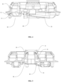
FIG. 1 is a schematic structural diagram of an inner-ring gas channel of an upside-entrainment burner in a related art; -
FIG. 2 is a schematic structural diagram of an upside-entrainment burner with a central swirl ejection structure of the present disclosure; -
FIG. 3 is a vertical view of an upside-entrainment burner with a central swirl ejection structure inFIG. 2 ; -
FIG. 4 is a sectional view along V1-V1 inFIG. 3 ; -
FIG. 5 is a sectional view along of V2-V2 inFIG. 3 ; -
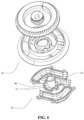
FIG. 6 is a decomposition diagram of an upside-entrainment burner with a central swirl ejection structure inFIG. 2 ; and -
FIG. 7 is a decomposition diagram of an upside-entrainment burner with a central swirl ejection structure inFIG. 6 in another perspective. - Reference signs in the drawings:
10, gas distribution seat; 11, sealing convex rib; 20, ejection pipe seat; 21, sealing groove; 30, inner-ring gas mixing chamber; 31, upper gas mixing chamber; 32, lower gas mixing chamber; 40, annular spiral chamber; and 50, inner-ring ejection channel. - This part will describe specific embodiments of the present disclosure in detail. Better embodiments of the present disclosure are shown in the accompanying drawings. The function of the accompanying drawings is to supplement the description of the text part of the specification with graphics, so that people can intuitively and vividly understand each technical feature and overall technical solution of the present disclosure, but it cannot be understood as a limitation to the protection scope of the present disclosure.
- In the description of the present disclosure, "a plurality of" means two or more, "greater than, less than, more than, and the like" means not including the number, and "above, below, within, and the like" means including the number. If "first" and "second are described, they are only used for distinguishing technical features, but cannot be construed as indicating or implying relative importance or implicitly indicating the number of indicated technical features or implicitly indicating the precedence relationship of the indicated technical features.
- In the description of the present disclosure, it should be understood that, if orientation description is involved, orientation or positional relationships indicated by "upper", "lower", "front", "rear", "left ", "right", and the like are orientations or positional relationships shown based on the accompanying drawings, which are merely used for the convenience of describing the present disclosure and simplifying the description, rather than indicating or implying that the devices or elements must have particular orientations, and constructed and operated in particular orientations. Thus, it cannot be construed as a limitation to the present disclosure.
- In the present disclosure, unless otherwise specified, words "arrange", "mount", "connect", and the like should be broadly understood. For example, the terms may refer to direct connection, or indirect connection through an intermediate medium, or may be fixed connection or detachable connection, or integrated molding, or may be mechanical connection, or may be communication inside two components or an interaction relationship of the two components. Those skilled in the art can reasonably determine specific meanings of the abovementioned words in the present disclosure in combination with the specific content of the technical solution.
- Referring to
FIG. 2 to FIG. 7 , an upside-entrainment burner with a central swirl ejection structure provided by the present disclosure includes agas distribution seat 10 and anejection pipe seat 20. - The
gas distribution seat 10 is arranged above theejection pipe seat 20. Thegas distribution seat 10 and theejection pipe seat 20 enclose to form an annular inner-ringgas mixing chamber 30 extending vertically. - The
ejection pipe seat 20 is provided with anannular spiral chamber 40 and an inner-ring ejection channel 50. The upper part of theannular spiral chamber 40 is communicated with the inner-ringgas mixing chamber 30, and the lower part is communicated with the inner-ring ejection channel 50. Theannular spiral chamber 40 is arranged in an annular spiral structure; and in the gas flowing and rotating direction, the size of the cross section of theannular spiral chamber 40 is gradually reduced. - In the present disclosure, the
ejection pipe seat 20 is provided with theannular spiral chamber 40 and the inner-ring ejection channel 50, and theannular spiral chamber 40 is arranged in the annular spiral structure, so that gas may form a spirally rotating and ascending gas flow in the annularspiral chamber 40. The size of the cross section of theannular spiral chamber 40 is gradually reduced, so that the gas will be gradually compressed and accelerated to flow as it rotating and flowing forward, thereby effectively improving the mixing ratio of fuel and air, and improving the ejection performance of the inner-ring gas supply channel in the upside-entrainment burner and the heat efficiency of the overall burner. According to the present disclosure, inner-ring gas is rotated, accelerated and compressed in limited arrangement space of a furnace seat of an upside-entrainment burner, which effectively improves the ejection performance of an ejection pipe and the heat efficiency of the overall burner. - A lower wall surface of the inner-
ring ejection channel 50 is obliquely arranged; and in the flowing and forward feeding direction of the gas, the size of the cross section of the inner-ring ejection channel 50 is gradually reduced. The lower wall surface of the inner-ring ejection channel 50 is obliquely arranged, and a structural design is simple, that is, the size of the cross section of the inner-ring ejection channel 50 is gradually reduced, thereby achieving effects of compressing and feeding the gas. - In some embodiments, the inner-ring
gas mixing chamber 30 includes an uppergas mixing chamber 31 and a lowergas mixing chamber 32 that are communicated with each other. The uppergas mixing chamber 31 is arranged above the lowergas mixing chamber 32; and the lowergas mixing chamber 32 is communicated with theannular spiral chamber 40. The inner-ringgas mixing chamber 30 is layered into a multi-layer gas mixing chamber structure, so that a further mixing effect will be achieved on the gas during a rotating and ascending process of the gas due to a change of a cylinder diameter. - Specifically, the size of the cross section of the lower
gas mixing chamber 32 in a horizontal radial direction is greater than that of the cross section of the uppergas mixing chamber 31 in the horizontal radial direction; and the size of the cross section of theannular spiral chamber 40 is greater than that of the cross section of the lowergas mixing chamber 32 in the horizontal radial direction. The sizes of the cross sections of the three layers of gas mixing chamber space from bottom to top are gradually reduced. During supplying upward, rotating, and ascending, the gas will be rotated, compressed, and accelerated repeatedly, the gas flows smoothly and has a good mixing effect, and the ejecting coefficient at a fire hole of a fire cap is high. - In this embodiment, in order to ensure a sealing effect, the
gas distribution seat 10 and theejection pipe seat 20 are provided with a sealingconvex rib 11 and a sealinggroove 21 that fit each other; and the sealingconvex rib 11 and the sealinggroove 21 are arranged on the outer edges of the inner-ring ejection channel 50 and theannular spiral chamber 40. The sealingconvex rib 11 and the sealinggroove 21 fit each other, so that an effective sealing anti-leakage effect can be achieved after thedistribution seat 10 and theejection pipe seat 20 are spliced. - In this embodiment, simulation models are respectively established according to an old central ejection structure as shown in
FIG. 1 and a new central swirl ejection structure of the present disclosure to simulate parameters such as an ejecting coefficient and gas flow at a fire hole output position of an inner-ring fire cap. Analysis data is as shown in Table 1 as follows:Table 1 Mole fraction of propane Mole fraction of butane Mole fraction of oxygen Ejecting coefficient of fire hole outlet Flow velocity of fire hole outlet (m/s) Old Inner fire hole 0.043352596 0.014450869 0.19786218 0.63684 0.85475826 This Inner fire 0.038966 0.01298833 0.19908672 0.712912 1.2161015 embodiment hole 852 Inner flame stabilizing hole 0.038949 522 0.012982553 0.19909156 0.713247 1.1291533 - Further, simulation Geometric models established corresponding to pot using environments are respectively established for the old central swirl ejection structure in
FIG. 1 and a new central swirl ejection structure of the present disclosure, so as to simulate, calculate, and actually detect analysis data of heat efficiency as shown in Table 2 below:Table 2 Model Gas type Pot body absorption heat Heat load simulation value Simulated heat efficiency Hot body heat resistance Ideal simulated heat efficiency (after heat transfer correction) Actually detected heat load Actually detected heat efficiency Old Liquefied petroleum gas 1610 W 2354 W 68.4% 82 W 64.9% 2223 W 66.3% New Liquefied petroleum gas 1939 W 2970 W 65.3% 92 W 63.2% 2851 W 63.4% - It can be seen from Table 1 and Table 2 that the fire hole outlet ejecting coefficient, the outlet flow velocity, the simulated heat efficiency, and the actually detected heat efficiency of the upside-entrainment burner with the central swirl ejection structure of the present disclosure are obviously improved.
- Of course, the present disclosure is not limited to the above implementation manners. Technicians familiar with this field can also make equivalent deformations or replacements without violating the spirit of this disclosure. Those of ordinary skill in the art may also make equivalent deformations and replacements without departing from the spirit of the present disclosure. These equivalent deformations and replacements all included in the scope of the claims of the present application.
Claims (5)
- An upside-entrainment burner with a central swirl ejection structure, comprising a gas distribution seat (10) and an ejection pipe seat (20), whereinthe gas distribution seat (10) is arranged above the ejection pipe seat (20); the gas distribution seat (10) and the ejection pipe seat (20) enclose to form an annular inner-ring gas mixing chamber (30) extending vertically;the ejection pipe seat (20) is provided with an annular spiral chamber (40) and an inner-ring ejection channel (50); the upper part of the annular spiral chamber (40) is communicated with the inner-ring gas mixing chamber (30), and the lower part is communicated with the inner-ring ejection channel (50); the annular spiral chamber (40) is arranged in an annular spiral structure; and in the gas flowing and rotating direction, the size of the cross section of the annular spiral chamber (40) is gradually reduced.
- The upside-entrainment burner with a central swirl ejection structure according to claim 1, wherein a lower wall surface of the inner-ring ejection channel (50) is obliquely arranged; and in the flowing and forward feeding direction of the gas, the size of the cross section of the inner-ring ejection channel (50) is gradually reduced.
- The upside-entrainment burner with a central swirl ejection structure according to claim 1, wherein the inner-ring gas mixing chamber (30) comprises an upper gas mixing chamber (31) and a lower gas mixing chamber (32) that are communicated with each other; the upper gas mixing chamber (31) is arranged above the lower gas mixing chamber (32); and the lower gas mixing chamber (32) is communicated with the annular spiral chamber (40).
- The upside-entrainment burner with a central swirl ejection structure according to claim 3, wherein the size of the cross section of the lower gas mixing chamber (32) in a horizontal radial direction is greater than that of the cross section of the upper gas mixing chamber (31) in the horizontal radial direction; and the size of the cross section of the annular spiral chamber (40) is greater than that of the cross section of the lower gas mixing chamber (32) in the horizontal radial direction.
- The upside-entrainment burner with a central swirl ejection structure according to claim 1, wherein the gas distribution seat (10) and the ejection pipe seat (20) are provided with a sealing convex rib (11) and a sealing groove (21) that fit each other; and the sealing convex rib (11) and the sealing groove (21) are arranged on the outer edges of the inner-ring ejection channel (50) and the annular spiral chamber (40).
Applications Claiming Priority (1)
| Application Number | Priority Date | Filing Date | Title |
|---|---|---|---|
| CN202320399367.XU CN219530938U (en) | 2023-03-06 | 2023-03-06 | Upper air inlet combustor with central rotational flow injection structure |
Publications (3)
| Publication Number | Publication Date |
|---|---|
| EP4428438A1 true EP4428438A1 (en) | 2024-09-11 |
| EP4428438C0 EP4428438C0 (en) | 2025-12-10 |
| EP4428438B1 EP4428438B1 (en) | 2025-12-10 |
Family
ID=87581642
Family Applications (1)
| Application Number | Title | Priority Date | Filing Date |
|---|---|---|---|
| EP23181907.9A Active EP4428438B1 (en) | 2023-03-06 | 2023-06-27 | Burner with central swirl ejection structure |
Country Status (3)
| Country | Link |
|---|---|
| EP (1) | EP4428438B1 (en) |
| CN (1) | CN219530938U (en) |
| ES (1) | ES3061430T3 (en) |
Citations (2)
| Publication number | Priority date | Publication date | Assignee | Title |
|---|---|---|---|---|
| CN107036099A (en) * | 2017-06-01 | 2017-08-11 | 华帝股份有限公司 | Three-ring distributor and three-ring combustor using same |
| CN218763390U (en) * | 2022-12-15 | 2023-03-28 | 广东重尚美物联科技有限公司 | Multifunctional rotational flow platform gas system |
-
2023
- 2023-03-06 CN CN202320399367.XU patent/CN219530938U/en active Active
- 2023-06-27 EP EP23181907.9A patent/EP4428438B1/en active Active
- 2023-06-27 ES ES23181907T patent/ES3061430T3/en active Active
Patent Citations (2)
| Publication number | Priority date | Publication date | Assignee | Title |
|---|---|---|---|---|
| CN107036099A (en) * | 2017-06-01 | 2017-08-11 | 华帝股份有限公司 | Three-ring distributor and three-ring combustor using same |
| CN218763390U (en) * | 2022-12-15 | 2023-03-28 | 广东重尚美物联科技有限公司 | Multifunctional rotational flow platform gas system |
Also Published As
| Publication number | Publication date |
|---|---|
| EP4428438C0 (en) | 2025-12-10 |
| CN219530938U (en) | 2023-08-15 |
| EP4428438B1 (en) | 2025-12-10 |
| ES3061430T3 (en) | 2026-04-01 |
Similar Documents
| Publication | Publication Date | Title |
|---|---|---|
| EP4425048A1 (en) | Energy-efficient upside-entrainment burning system | |
| CN107339694B (en) | Stove burner and gas stove | |
| CN104964279B (en) | Cooker burner | |
| CN102345866A (en) | Combustor with multiple secondary air supply function | |
| CN102183016A (en) | Combustor assembly of multi-nozzle gas furnace for complete top air intake | |
| CN202101234U (en) | Multi-nozzle, complete upper gas-admission gas furnace combustion device assembly | |
| CN201180997Y (en) | Multi-point ejection stereo air intake combustor | |
| EP4428438A1 (en) | Burner with central swirl ejection structure | |
| CN201885228U (en) | Combustor with function of multi-supply of secondary air | |
| CN204574047U (en) | Distributor and there is its top intaking air gas combustion stove | |
| CN207214049U (en) | A kind of burner | |
| CN217383024U (en) | Burner and gas stove | |
| CN220551913U (en) | Gas injection pipe structure | |
| CN207162536U (en) | Burner with high efficiency | |
| CN104676592B (en) | A kind of burner with high efficiency | |
| CN220958452U (en) | A high-efficiency burner structure and stove | |
| CN221403046U (en) | Gas cavity structure for adjusting gas outlet pressure distribution and upper air inlet combustor | |
| CN211345305U (en) | Burner furnace end and kitchen range using same | |
| CN206130984U (en) | Fire cover for gas kitchen range | |
| CN219775720U (en) | Graded stable combustion disk for gas boiler | |
| CN206257703U (en) | A high-power gas stove | |
| CN201066117Y (en) | Combusting device | |
| CN224033795U (en) | A burner with a ring-shaped multi-head high-power burner structure | |
| CN210069934U (en) | Combined furnace end of pressure stabilizing burner | |
| CN223610110U (en) | Inner ring fire cover, burner and gas stove |
Legal Events
| Date | Code | Title | Description |
|---|---|---|---|
| PUAI | Public reference made under article 153(3) epc to a published international application that has entered the european phase |
Free format text: ORIGINAL CODE: 0009012 |
|
| STAA | Information on the status of an ep patent application or granted ep patent |
Free format text: STATUS: THE APPLICATION HAS BEEN PUBLISHED |
|
| AK | Designated contracting states |
Kind code of ref document: A1 Designated state(s): AL AT BE BG CH CY CZ DE DK EE ES FI FR GB GR HR HU IE IS IT LI LT LU LV MC ME MK MT NL NO PL PT RO RS SE SI SK SM TR |
|
| STAA | Information on the status of an ep patent application or granted ep patent |
Free format text: STATUS: REQUEST FOR EXAMINATION WAS MADE |
|
| 17P | Request for examination filed |
Effective date: 20250310 |
|
| GRAP | Despatch of communication of intention to grant a patent |
Free format text: ORIGINAL CODE: EPIDOSNIGR1 |
|
| STAA | Information on the status of an ep patent application or granted ep patent |
Free format text: STATUS: GRANT OF PATENT IS INTENDED |
|
| INTG | Intention to grant announced |
Effective date: 20250709 |
|
| GRAS | Grant fee paid |
Free format text: ORIGINAL CODE: EPIDOSNIGR3 |
|
| GRAA | (expected) grant |
Free format text: ORIGINAL CODE: 0009210 |
|
| STAA | Information on the status of an ep patent application or granted ep patent |
Free format text: STATUS: THE PATENT HAS BEEN GRANTED |
|
| AK | Designated contracting states |
Kind code of ref document: B1 Designated state(s): AL AT BE BG CH CY CZ DE DK EE ES FI FR GB GR HR HU IE IS IT LI LT LU LV MC ME MK MT NL NO PL PT RO RS SE SI SK SM TR |
|
| REG | Reference to a national code |
Ref country code: CH Ref legal event code: F10 Free format text: ST27 STATUS EVENT CODE: U-0-0-F10-F00 (AS PROVIDED BY THE NATIONAL OFFICE) Effective date: 20251210 Ref country code: GB Ref legal event code: FG4D |
|
| REG | Reference to a national code |
Ref country code: DE Ref legal event code: R096 Ref document number: 602023009467 Country of ref document: DE |
|
| REG | Reference to a national code |
Ref country code: IE Ref legal event code: FG4D |
|
| U01 | Request for unitary effect filed |
Effective date: 20251217 |
|
| U07 | Unitary effect registered |
Designated state(s): AT BE BG DE DK EE FI FR IT LT LU LV MT NL PT RO SE SI Effective date: 20260102 |
|
| REG | Reference to a national code |
Ref country code: ES Ref legal event code: FG2A Ref document number: 3061430 Country of ref document: ES Kind code of ref document: T3 Effective date: 20260401 |
|
| PG25 | Lapsed in a contracting state [announced via postgrant information from national office to epo] |
Ref country code: NO Free format text: LAPSE BECAUSE OF FAILURE TO SUBMIT A TRANSLATION OF THE DESCRIPTION OR TO PAY THE FEE WITHIN THE PRESCRIBED TIME-LIMIT Effective date: 20260310 |
|
| PG25 | Lapsed in a contracting state [announced via postgrant information from national office to epo] |
Ref country code: HR Free format text: LAPSE BECAUSE OF FAILURE TO SUBMIT A TRANSLATION OF THE DESCRIPTION OR TO PAY THE FEE WITHIN THE PRESCRIBED TIME-LIMIT Effective date: 20251210 |
|
| PG25 | Lapsed in a contracting state [announced via postgrant information from national office to epo] |
Ref country code: RS Free format text: LAPSE BECAUSE OF FAILURE TO SUBMIT A TRANSLATION OF THE DESCRIPTION OR TO PAY THE FEE WITHIN THE PRESCRIBED TIME-LIMIT Effective date: 20260310 |