EP4428421A1 - Fluid-conveying hose - Google Patents
Fluid-conveying hose Download PDFInfo
- Publication number
- EP4428421A1 EP4428421A1 EP22889721.1A EP22889721A EP4428421A1 EP 4428421 A1 EP4428421 A1 EP 4428421A1 EP 22889721 A EP22889721 A EP 22889721A EP 4428421 A1 EP4428421 A1 EP 4428421A1
- Authority
- EP
- European Patent Office
- Prior art keywords
- hose
- electrically conductive
- rubber
- resistance value
- electrical resistance
- Prior art date
- Legal status (The legal status is an assumption and is not a legal conclusion. Google has not performed a legal analysis and makes no representation as to the accuracy of the status listed.)
- Pending
Links
Images


Classifications
-
- B—PERFORMING OPERATIONS; TRANSPORTING
- B32—LAYERED PRODUCTS
- B32B—LAYERED PRODUCTS, i.e. PRODUCTS BUILT-UP OF STRATA OF FLAT OR NON-FLAT, e.g. CELLULAR OR HONEYCOMB, FORM
- B32B1/00—Layered products having a non-planar shape
- B32B1/08—Tubular products
-
- B—PERFORMING OPERATIONS; TRANSPORTING
- B32—LAYERED PRODUCTS
- B32B—LAYERED PRODUCTS, i.e. PRODUCTS BUILT-UP OF STRATA OF FLAT OR NON-FLAT, e.g. CELLULAR OR HONEYCOMB, FORM
- B32B25/00—Layered products comprising a layer of natural or synthetic rubber
- B32B25/10—Layered products comprising a layer of natural or synthetic rubber next to a fibrous or filamentary layer
-
- F—MECHANICAL ENGINEERING; LIGHTING; HEATING; WEAPONS; BLASTING
- F16—ENGINEERING ELEMENTS AND UNITS; GENERAL MEASURES FOR PRODUCING AND MAINTAINING EFFECTIVE FUNCTIONING OF MACHINES OR INSTALLATIONS; THERMAL INSULATION IN GENERAL
- F16L—PIPES; JOINTS OR FITTINGS FOR PIPES; SUPPORTS FOR PIPES, CABLES OR PROTECTIVE TUBING; MEANS FOR THERMAL INSULATION IN GENERAL
- F16L11/00—Hoses, i.e. flexible pipes
- F16L11/04—Hoses, i.e. flexible pipes made of rubber or flexible plastics
- F16L11/08—Hoses, i.e. flexible pipes made of rubber or flexible plastics with reinforcements embedded in the wall
-
- F—MECHANICAL ENGINEERING; LIGHTING; HEATING; WEAPONS; BLASTING
- F16—ENGINEERING ELEMENTS AND UNITS; GENERAL MEASURES FOR PRODUCING AND MAINTAINING EFFECTIVE FUNCTIONING OF MACHINES OR INSTALLATIONS; THERMAL INSULATION IN GENERAL
- F16L—PIPES; JOINTS OR FITTINGS FOR PIPES; SUPPORTS FOR PIPES, CABLES OR PROTECTIVE TUBING; MEANS FOR THERMAL INSULATION IN GENERAL
- F16L11/00—Hoses, i.e. flexible pipes
- F16L11/04—Hoses, i.e. flexible pipes made of rubber or flexible plastics
- F16L11/08—Hoses, i.e. flexible pipes made of rubber or flexible plastics with reinforcements embedded in the wall
- F16L11/081—Hoses, i.e. flexible pipes made of rubber or flexible plastics with reinforcements embedded in the wall comprising one or more layers of a helically wound cord or wire
- F16L11/083—Hoses, i.e. flexible pipes made of rubber or flexible plastics with reinforcements embedded in the wall comprising one or more layers of a helically wound cord or wire three or more layers
-
- F—MECHANICAL ENGINEERING; LIGHTING; HEATING; WEAPONS; BLASTING
- F16—ENGINEERING ELEMENTS AND UNITS; GENERAL MEASURES FOR PRODUCING AND MAINTAINING EFFECTIVE FUNCTIONING OF MACHINES OR INSTALLATIONS; THERMAL INSULATION IN GENERAL
- F16L—PIPES; JOINTS OR FITTINGS FOR PIPES; SUPPORTS FOR PIPES, CABLES OR PROTECTIVE TUBING; MEANS FOR THERMAL INSULATION IN GENERAL
- F16L11/00—Hoses, i.e. flexible pipes
- F16L11/04—Hoses, i.e. flexible pipes made of rubber or flexible plastics
- F16L11/12—Hoses, i.e. flexible pipes made of rubber or flexible plastics with arrangements for particular purposes, e.g. specially profiled, with protecting layer, heated, electrically conducting
- F16L11/127—Hoses, i.e. flexible pipes made of rubber or flexible plastics with arrangements for particular purposes, e.g. specially profiled, with protecting layer, heated, electrically conducting electrically conducting
-
- F—MECHANICAL ENGINEERING; LIGHTING; HEATING; WEAPONS; BLASTING
- F16—ENGINEERING ELEMENTS AND UNITS; GENERAL MEASURES FOR PRODUCING AND MAINTAINING EFFECTIVE FUNCTIONING OF MACHINES OR INSTALLATIONS; THERMAL INSULATION IN GENERAL
- F16L—PIPES; JOINTS OR FITTINGS FOR PIPES; SUPPORTS FOR PIPES, CABLES OR PROTECTIVE TUBING; MEANS FOR THERMAL INSULATION IN GENERAL
- F16L33/00—Arrangements for connecting hoses to rigid members; Rigid hose-connectors, i.e. single members engaging both hoses
- F16L33/01—Arrangements for connecting hoses to rigid members; Rigid hose-connectors, i.e. single members engaging both hoses specially adapted for hoses having a multi-layer wall
Definitions
- the present invention relates to a fluid-transporting hose and particularly relates to a fluid-transporting hose used for transferring a fluid between a ship and a ship.
- a marine hose is used to transport crude oil or the like by connecting a tanker or the like on the sea and an onshore facility or the like (for example, see Patent Document 1).
- a use situation is different from that of the marine hose, when a fluid is transferred between a ship and a ship, a large-diameter fluid-transporting hose, such as a marine hose, is used and a hose line is formed so as to be extended between the ships.
- This hose line is required to have a function of preventing arc discharge caused by a stray current generated by a potential difference between the ship and the ship.
- a function of preventing spark caused by electrification current generated by friction between the transported fluid and a wall surface of a hose flow path is also required.
- To prevent the arc discharge it is necessary to increase an electrical resistance value of the hose line (transporting hose) to some extent to block the stray current.
- to prevent spark it is necessary to reduce the electrical resistance value to some extent such that the electrification current is easily discharged. Therefore, the electrical resistance value of the hose line needs to be maintained within an appropriate predetermined range to prevent both the arc discharge and the spark.
- an electrical resistance value of vulcanized rubber forming the fluid-transporting hose changes (decreases) over time. Therefore, unlike a marine hose in which a steel cord (metal wire) is used in a reinforcing layer, in a fluid-transporting hose in which a metal wire is not used, it is necessary to more accurately maintain the electrical resistance value between both end portions of the fluid-transporting hose in an appropriate predetermined range at the time of manufacturing the hose in consideration of the change over time.
- the hose line is used in a bent state, and the electrical resistance value of the transporting hose changes depending on a degree of bending deformation. That is, the electrical resistance value between both the end portions of the hose becomes larger in the bent state than the transporting hose in a straight state. Therefore, there is room for improvement in maintaining the electrical resistance value between both the end portions of the hose at the time of transferring a fluid between a ship and a ship in an appropriate predetermined range for a long period of time.
- Patent Document 1 JP 2017-137957 A
- An object of the present invention is to provide a fluid-transporting hose that allows maintaining an electrical resistance value between both end portions of the hose at the time of transferring a fluid between a ship and a ship in an appropriate predetermined range for a long period of time.
- a fluid-transporting hose of an embodiment of the present invention may include a hose body and connection fittings.
- the connection fittings may be fixed to both end portions of the hose body.
- the hose body may be formed by stacking an inner surface rubber layer, a reinforcing layer, and an outer surface rubber layer in order.
- the reinforcing layer may be a multilayer structure of a reinforcing fiber layer and an intermediate rubber layer.
- an electrically conductive rubber having a smallest electrical resistance value per unit cross-sectional area and unit length may helically extend at an interval in a longitudinal direction of the hose.
- the electrically conductive rubber having the smallest electrical resistance value per the unit cross-sectional area and the unit length helically extends at the intervals in the longitudinal direction of the hose.
- the electrical resistance value between both the end portions of the hose can be increased by helically extending the electrically conductive rubber as described above and guiding electricity flowing through the hose body to the electrically conductive rubber having a further long entire length.
- a fluid-transporting hose of the present invention will be described below based on embodiments illustrated in the drawings.
- a fluid-transporting hose 1 (hereinafter referred to as a hose 1) of an embodiment of the present invention is used in a hose line Ln extended between a ship 8 and a ship 8.
- the hose line Ln is formed by connecting a plurality of the hoses 1, but the hose line Ln may be formed by the single hose 1. Both end portions of the hose line Ln are detachably connected to hose fixing portions 9 of the respective ships 8.
- a fluid F is transferred from one ship 8 to the other ship 8 through the hose line Ln.
- the fluid F include any various fluids F including crude oil, gasoline, and LPG, and can be transferred through the hose line Ln.
- the hose 1 includes a hose body 3 and respective connection fittings 2 connected to both the end portions of the hose body 3 in a longitudinal direction. That is, the hose body 3 extends between the respective connection fittings 2.
- a flow path 1a communicates with the hose body 3 and each of the connection fittings 2 in the longitudinal direction.
- the length of one hose 1 is 9.1 m or more and 11.8 m or less, for example, and an inner diameter (flow path diameter) of the hose body 3 is 200 mm or more and 300 mm or less, for example.
- a dot-dash line CL in the drawing is a center axis line extending in the longitudinal direction of the hose 1.
- connection fitting 2 has a disc-shaped flange 2a and a cylindrical nipple 2b joined to the flange 2a and having a leading edge portion side inserted into the hose body 3.
- fixing rings 2c are disposed to project at intervals in the longitudinal direction.
- the hose body 3 includes an inner surface rubber layer 4, an outer surface rubber layer 5, a reinforcing layer group (reinforcing layers 6) disposed between the inner surface rubber layer 4 and the outer surface rubber layer 5, and a band-like electrically conductive rubber 7.
- the inner surface rubber layer 4, the reinforcing layer group (reinforcing layers 6), and the outer surface rubber layer 5 are coaxially layered in this order.
- the electrically conductive rubber 7 helically extends at an interval d in the longitudinal direction of the hose on an outer circumferential side of the flow path 1a.
- the interval d is an interval between adjacent spirals of the electrically conductive rubber 7.
- the hose body 3 may be provided with another necessary member as appropriate.
- the inner surface rubber layer 4 comes into contact with the fluid F transferred through the hose line Ln, a rubber having appropriate characteristics is employed according to the type of the fluid F.
- the inner surface rubber layer 4 when crude oil or the like is transported is made of, for example, acrylonitrile rubber having excellent oil resistance.
- the layer thickness of the inner surface rubber layer 4 is, for example, 4 mm or more and 6 mm or less.
- a lining layer made of, for example, nylon fiber is coaxially embedded in the inner surface rubber layer 4.
- the outer surface rubber layer 5 a rubber having appropriate characteristics is employed in consideration of wear resistance and the like.
- the outer surface rubber layer 5 is made of, for example, chloroprene rubber or the like.
- the layer thickness of the outer surface rubber layer 5 is, for example, 6 mm or more and 10 mm or less.
- a lining layer made of, for example, nylon fiber is coaxially embedded in the outer surface rubber layer 5.
- the reinforcing layer group is configured to by the inner reinforcing layer 6 and the outer reinforcing layer 6.
- the reinforcing layer group can be configured by stacking a single or the appropriate number of reinforcing layers 6.
- the reinforcing layer group is made of non-metal in which a metal wire, such as a steel cord, is not used.
- a metallic member (wire) is used only for bead rings 6R disposed at both the end portions of the respective reinforcing layers 6 in the longitudinal direction.
- the bead rings 6R of the respective reinforcing layers 6 are engaged with the corresponding fixing rings 2c such that the respective reinforcing layers 6 are fixed to the connection fittings 2.
- each of the reinforcing layers 6 is a multilayer structure of reinforcing fiber layers 6a and intermediate rubber layers 6b. Basically, both upper and lower surfaces of the reinforcing fiber layer 6a are covered with the intermediate rubber layers 6b. The numbers of the reinforcing fiber layers 6a and the intermediate rubber layers 6b constituting each of the reinforcing layer 6 are appropriately determined.
- the reinforcing fiber layer 6a is formed by the large number of fiber cords.
- the various known resins can be used, and, for example, polyester or the like is used.
- the layer thickness of one layer of each of the reinforcing fiber layers 6a is, for example, 0.7 mm or more and 1.0 mm or less.
- the reinforcing fiber layer 6a has a considerably larger electrical resistance value than rubber and can be regarded as an insulating material in an embodiment of the present invention.
- the connection fitting 2 is a good conductor.
- the intermediate rubber layer 6b is a rubber having an excellent adhesive strength, and firmly joins members layered adjacent to one another.
- Various known adhesive rubbers can be used for the intermediate rubber layer 6b.
- the layer thickness of one layer of each of the intermediate rubber layers 6b is, for example, 0.3 mm or more and 0.5 mm or less.
- the hose 1 has a special specification in which the band-like electrically conductive rubber 7 is helically extended at intervals in the longitudinal direction of the hose.
- the electrically conductive rubber 7 is a rubber having the smallest electrical resistance value per unit cross-sectional area and unit length among the rubbers forming the inner surface rubber layer 4, the outer surface rubber layer 5, and the intermediate rubber layers 6b. Therefore, the electrically conductive rubber 7 is made of rubber through which electricity flows most easily in the hose body 3 and is a member through which electricity flows most easily in the hose body 3.
- the electrically conductive rubber 7 is formed by compounding conductive carbon or the like with a blend of natural rubber and styrene-butadiene rubber, for example.
- one band-like electrically conductive rubber 7 is disposed in the outer surface rubber layer 5 but can be disposed in the inner surface rubber layer 4 or in the intermediate rubber layer 6b. That is, the electrically conductive rubber 7 can be constituted by the rubber forming the inner surface rubber layer 4, the outer surface rubber layer 5, or the intermediate rubber layer 6b. In this embodiment, the electrically conductive rubber 7 is embedded in the outer surface rubber layer 5 but can be exposed on an outer surface of the outer surface rubber layer 5 or can be disposed on a boundary surface between the outer surface rubber layer 5 and the reinforcing layer 6.
- the electrically conductive rubber 7 is embedded in the outer surface rubber layer 5, disposed on the boundary surface between the outer surface rubber layer 5 and the reinforcing layer 6, or disposed on the intermediate rubber layer 6b.
- the electrically conductive rubber 7 is embedded in the inner surface rubber layer 4, it is easily affected by the fluid F flowing through the flow path 1a.
- the electrically conductive rubber 7 extends substantially over the entire length of the hose body 3. It is preferable that respective both the end portions of the electrically conductive rubber 7 in the longitudinal direction directly abut on the connection fittings 2 at both the end portions of the hose 1. Even when the electrically conductive rubber 7 and the connection fittings 2 do not directly abut on, a good conductor is disposed between them to have a specification of smoothly conducting electricity.
- the electrical resistance value between the connection fitting 2 at one end portion and the connection fitting 2 at the other end portion of the hose 1 (between both the end portions of the hose) greatly depends on the electrical resistance value of the entire length of the electrically conductive rubber 7.
- the resistivity ⁇ is a fixed value determined by the type of rubber.
- the electrical resistance value R becomes large, and as the cross-sectional area S is made larger and as the entire length L is made shorter, the electrical resistance value R becomes small.
- the electrically conductive rubber 7 helically extends at the interval d in the longitudinal direction of the hose, its entire length can be made substantially longer than the entire length of the hose.
- the cross-sectional area S can be arbitrarily set. Therefore, the electrical resistance value R of the entire length of the electrically conductive rubber 7 can be set in a desired range, and accordingly, the electrical resistance value between both the end portions of the hose is easily set in an appropriate predetermined range (standard range).
- the forms (cross-sectional area S, entire length L) of the electrically conductive rubber 7 are appropriately set to determine the electrical resistance value R of the entire length of the electrically conductive rubber 7 in a new condition. This makes it easy to maintain the electrical resistance value between both the end portions of the hose in the appropriate predetermined range (standard range) for a long period of time.
- the electrical resistance value of the entire length of the hose in a new condition is determined in consideration of the above-described secular change of the electrical resistance value of the vulcanized rubber and fluctuation of the electrical resistance value due to the bending of the hose 1 during use.
- the electrical resistance value of the entire length of the hose measured in accordance with a stipulation of ISO8031 in a state where the hose body 3 is extended straight with the hose 1 in a new condition is preferably set to 100000 S2 or more and 600000 S2 or less.
- the hose 1 in a new condition refers to a period from the manufacture of the hose 1 until, for example, 30 days have elapsed.
- the electrical resistance value of the entire length of the hose at the time of shipment inspection is set to 100000 S2 or more and 600000 S2 or less. Thereby, the electrical resistance value of the entire length of the hose can be maintained in the standard range of 25000 S2 or more and 1000000 S2 or less for a long period of time.
- the cross-sectional area S and the entire length L of the electrically conductive rubber 7 only need to be set such that the electrical resistance value of the entire length of the hose becomes 100000 S2 or more and 600000 S2 or less with the hose 1 in a new condition.
- a degree of freedom of the layer thickness of the electrically conductive rubber 7 is low, for example, about 1.0 mm or more and 3.0 mm or less.
- the cross-sectional shape of the electrically conductive rubber 7 is not particularly limited but is substantially rectangular because there is no degree of freedom of the layer thickness. Therefore, the width dimension W is easily adjusted for the cross-sectional area S.
- the width dimension W of the electrically conductive rubber 7 is set to, for example, 10 mm or more.
- the width dimension W of the electrically conductive rubber 7 is set to, for example, 50% or less of the spiral pitch P.
- the entire length L of the electrically conductive rubber 7 can be adjusted by changing the spiral pitch P. Therefore, the spiral pitch P only needs to be set such that the degree of freedom of the entire length L becomes relatively high and the desired entire length L is obtained.
- the electrical resistance value between both the end portions of the hose can be increased by guiding the electricity flowing through the hose body 3 to the electrically conductive rubber 7 that is helically extended and has the further long entire length L.
- the electrical resistance value between both the end portions of the hose is easily maintained in the appropriate predetermined range (standard range) for a long period of time.
- the electrical resistance value per unit cross-sectional area and unit length of the rubber disposed adjacent to the electrically conductive rubber 7 is made as large as possible to obtain an insulation specification.
- the electrical resistance value per unit cross-sectional area and unit length of the rubber disposed adjacent to the electrically conductive rubber 7 is set to 5 times or more and more preferably 10 times or more the electrical resistance value per unit cross-sectional area and unit length of the electrically conductive rubber 7.
- the entire surface of the electrically conductive rubber 7 may be covered with a rubber having the insulation specification.
- the outer surface rubber layer 5 is configured by a rubber having the insulation specification and the electrically conductive rubber 7 embedded in the rubber having the insulation specification.
- the spiral pitch P of the electrically conductive rubber 7 is set to be constant over the entire length of the hose.
- the hose 1 in use is in a bent state, and the hose body 3 has a bent range and a substantially non-bent range (straight range).
- the electrical resistance value significantly fluctuates in the bending range.
- the spiral pitch P of the electrically conductive rubber 7 is made further small and the electrically conductive rubber 7 is densely wound, the degree of bending of the electrically conductive rubber 7 is alleviated even when the hose body 3 is bent as compared with the case where the spiral pitch P is large and the electrically conductive rubber 7 is sparsely wound. Accordingly, the fluctuation of the electrical resistance value can be suppressed. Therefore, as exemplified in FIG. 6 , the spiral pitch P of the electrically conductive rubber 7 can be changed in the longitudinal direction of the hose.
- the spiral pitch P is divided into relatively long ranges PL and a relatively short range PS.
- the relatively short range PS is set at a central portion of the hose 1 in the longitudinal direction (for example, a range of 40% of the entire length of the hose body 3 with the longitudinal center position as the center) bent in a state where a radius of curvature is the smallest in the hose body 3 when the hose 1 is used.
- the relatively long ranges PL of the spiral pitches P are set at both the end portions of the hose 1 in the longitudinal direction.
- the specification exemplified in FIG. 6 is advantageous in suppressing the fluctuation of the electrical resistance value between both the end portions of the hose while the hose 1 is used.
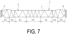
- the spiral pitch P of the electrically conductive rubber 7 can be changed in the longitudinal direction of the hose.
- the ranges PS in which the spiral pitch P is relatively short are set at positions equivalent to the vicinity of the end positions of the nipples 2b of the connection fittings 2 in addition to the central portion of the hose 1 in the longitudinal direction. Ranges other than the relatively short range PS are set as the relatively long ranges PL.
- the specification exemplified in FIG. 7 is advantageous in suppressing the fluctuation of the electrical resistance value between both the end portions of the hose while the hose 1 is used.
- Example 1 a hose sample (Example) having the same structure as exemplified in FIGS. 2 to 5 and a hose sample (Comparative Example) different from Example only in a form of an electrically conductive rubber were manufactured, and electrical resistance values of entire lengths of the hoses of the respective samples were measured in accordance with the stipulation of ISO8031.
- Table 1 The only difference between Example and Comparative Example is a spiral pitch of the electrically conductive rubber, and in Comparative Example, the adjacent spirals of the electrically conductive rubber were overlapped with one another to set the interval d to 0.
- the electrically conductive rubber of each sample had the width dimension W of 50 mm and a layer thickness of 1.5 mm.
- Example 1 From the results of Table 1, it can be seen that in Example in which the electrical resistance value measured in the straight state in the new condition was 468000 ⁇ , the electrical resistance value of the entire length of the hose can be maintained in the standard range of 25000 S2 or more and 1000000 S2 or less even in the bent state in the new condition and in the straight state after elapse of one year from the manufacture.
Landscapes
- Engineering & Computer Science (AREA)
- General Engineering & Computer Science (AREA)
- Mechanical Engineering (AREA)
- Rigid Pipes And Flexible Pipes (AREA)
- Laminated Bodies (AREA)
Abstract
Description
- The present invention relates to a fluid-transporting hose and particularly relates to a fluid-transporting hose used for transferring a fluid between a ship and a ship.
- A marine hose is used to transport crude oil or the like by connecting a tanker or the like on the sea and an onshore facility or the like (for example, see Patent Document 1). Although a use situation is different from that of the marine hose, when a fluid is transferred between a ship and a ship, a large-diameter fluid-transporting hose, such as a marine hose, is used and a hose line is formed so as to be extended between the ships.
- This hose line is required to have a function of preventing arc discharge caused by a stray current generated by a potential difference between the ship and the ship. In addition, a function of preventing spark caused by electrification current generated by friction between the transported fluid and a wall surface of a hose flow path is also required. To prevent the arc discharge, it is necessary to increase an electrical resistance value of the hose line (transporting hose) to some extent to block the stray current. On the other hand, to prevent spark, it is necessary to reduce the electrical resistance value to some extent such that the electrification current is easily discharged. Therefore, the electrical resistance value of the hose line needs to be maintained within an appropriate predetermined range to prevent both the arc discharge and the spark. Moreover, it is known that an electrical resistance value of vulcanized rubber forming the fluid-transporting hose changes (decreases) over time. Therefore, unlike a marine hose in which a steel cord (metal wire) is used in a reinforcing layer, in a fluid-transporting hose in which a metal wire is not used, it is necessary to more accurately maintain the electrical resistance value between both end portions of the fluid-transporting hose in an appropriate predetermined range at the time of manufacturing the hose in consideration of the change over time.
- Further, the hose line is used in a bent state, and the electrical resistance value of the transporting hose changes depending on a degree of bending deformation. That is, the electrical resistance value between both the end portions of the hose becomes larger in the bent state than the transporting hose in a straight state. Therefore, there is room for improvement in maintaining the electrical resistance value between both the end portions of the hose at the time of transferring a fluid between a ship and a ship in an appropriate predetermined range for a long period of time.
- Patent Document 1:
JP 2017-137957 A - An object of the present invention is to provide a fluid-transporting hose that allows maintaining an electrical resistance value between both end portions of the hose at the time of transferring a fluid between a ship and a ship in an appropriate predetermined range for a long period of time.
- To achieve the object described above, a fluid-transporting hose of an embodiment of the present invention may include a hose body and connection fittings. The connection fittings may be fixed to both end portions of the hose body. The hose body may be formed by stacking an inner surface rubber layer, a reinforcing layer, and an outer surface rubber layer in order. The reinforcing layer may be a multilayer structure of a reinforcing fiber layer and an intermediate rubber layer. Among rubbers forming the inner surface rubber layer, the outer surface rubber layer, and the intermediate rubber layer, an electrically conductive rubber having a smallest electrical resistance value per unit cross-sectional area and unit length may helically extend at an interval in a longitudinal direction of the hose.
- According to an embodiment of the present invention, among the rubbers constituting the hose body, the electrically conductive rubber having the smallest electrical resistance value per the unit cross-sectional area and the unit length helically extends at the intervals in the longitudinal direction of the hose. The electrical resistance value between both the end portions of the hose can be increased by helically extending the electrically conductive rubber as described above and guiding electricity flowing through the hose body to the electrically conductive rubber having a further long entire length. By appropriately setting the form of the electrically conductive rubber, the electrical resistance value between both the end portions of the hose can be easily maintained in an appropriate predetermined range.
- In addition, even when the hose body is bent, excessive deformation is less likely to occur in the electrically conductive rubber helically extending as described above. Accordingly, it is advantageous to suppress fluctuation of the electrical resistance value between both the end portions of the hose when the hose is used. Therefore, by using the fluid-transporting hose of an embodiment of the present invention, it is advantageous to maintain the electrical resistance value between both the end portions of the hose at the time of transferring a fluid between a ship and a ship in the appropriate predetermined range for a long period of time.
-
-
FIG. 1 is an explanatory diagram exemplifying a use state of a fluid-transporting hose according to an embodiment of the present invention. -
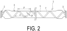
FIG. 2 is an explanatory diagram exemplifying the fluid-transporting hose according to an embodiment of the present invention in a straight state in a side view. -
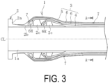
FIG. 3 is an explanatory diagram exemplifying one end portion of the fluid-transporting hose ofFIG. 2 in a longitudinal cross-sectional view. -
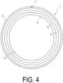
FIG. 4 is a cross-sectional view taken along A-A ofFIG. 3 . -
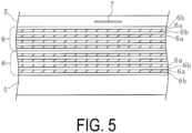
FIG. 5 is an explanatory diagram exemplifying an enlarged part ofFIG. 3 . -
FIG. 6 is an explanatory diagram schematically exemplifying a modified example of spiral pitches of an electrically conductive rubber. -
FIG. 7 is an explanatory view schematically exemplifying another modified example of the spiral pitches of the electrically conductive rubber. - A fluid-transporting hose of the present invention will be described below based on embodiments illustrated in the drawings.
- As exemplified in
FIG. 1 , a fluid-transporting hose 1 (hereinafter referred to as a hose 1) of an embodiment of the present invention is used in a hose line Ln extended between a ship 8 and a ship 8. In this embodiment, the hose line Ln is formed by connecting a plurality of thehoses 1, but the hose line Ln may be formed by thesingle hose 1. Both end portions of the hose line Ln are detachably connected tohose fixing portions 9 of the respective ships 8. A fluid F is transferred from one ship 8 to the other ship 8 through the hose line Ln. Examples of the fluid F include any various fluids F including crude oil, gasoline, and LPG, and can be transferred through the hose line Ln. - As exemplified in
FIGS. 2 to 4 , thehose 1 includes ahose body 3 andrespective connection fittings 2 connected to both the end portions of thehose body 3 in a longitudinal direction. That is, thehose body 3 extends between therespective connection fittings 2. A flow path 1a communicates with thehose body 3 and each of theconnection fittings 2 in the longitudinal direction. The length of onehose 1 is 9.1 m or more and 11.8 m or less, for example, and an inner diameter (flow path diameter) of thehose body 3 is 200 mm or more and 300 mm or less, for example. A dot-dash line CL in the drawing is a center axis line extending in the longitudinal direction of thehose 1. - The
connection fitting 2 has a disc-shaped flange 2a and acylindrical nipple 2b joined to theflange 2a and having a leading edge portion side inserted into thehose body 3. On an outer circumferential surface of thenipple 2b,fixing rings 2c are disposed to project at intervals in the longitudinal direction. - The
hose body 3 includes an innersurface rubber layer 4, an outersurface rubber layer 5, a reinforcing layer group (reinforcing layers 6) disposed between the innersurface rubber layer 4 and the outersurface rubber layer 5, and a band-like electricallyconductive rubber 7. The innersurface rubber layer 4, the reinforcing layer group (reinforcing layers 6), and the outersurface rubber layer 5 are coaxially layered in this order. The electricallyconductive rubber 7 helically extends at an interval d in the longitudinal direction of the hose on an outer circumferential side of the flow path 1a. The interval d is an interval between adjacent spirals of the electricallyconductive rubber 7. A length indicated by a sign P described inFIG. 2 is a distance in the longitudinal direction (hereinafter referred to as a spiral pitch P) of the hose when the electricallyconductive rubber 7 helically extends one round in thehose body 3. Even when the spiral pitch P is the same, as a width dimension W of the electricallyconductive rubber 7 increases, the interval d decreases. Thehose body 3 may be provided with another necessary member as appropriate. - Since the inner
surface rubber layer 4 comes into contact with the fluid F transferred through the hose line Ln, a rubber having appropriate characteristics is employed according to the type of the fluid F. The innersurface rubber layer 4 when crude oil or the like is transported is made of, for example, acrylonitrile rubber having excellent oil resistance. The layer thickness of the innersurface rubber layer 4 is, for example, 4 mm or more and 6 mm or less. A lining layer made of, for example, nylon fiber is coaxially embedded in the innersurface rubber layer 4. - For the outer
surface rubber layer 5, a rubber having appropriate characteristics is employed in consideration of wear resistance and the like. The outersurface rubber layer 5 is made of, for example, chloroprene rubber or the like. The layer thickness of the outersurface rubber layer 5 is, for example, 6 mm or more and 10 mm or less. A lining layer made of, for example, nylon fiber is coaxially embedded in the outersurface rubber layer 5. - In this embodiment, the reinforcing layer group is configured to by the inner reinforcing
layer 6 and the outer reinforcinglayer 6. The reinforcing layer group can be configured by stacking a single or the appropriate number of reinforcinglayers 6. The reinforcing layer group is made of non-metal in which a metal wire, such as a steel cord, is not used. However, a metallic member (wire) is used only for bead rings 6R disposed at both the end portions of the respective reinforcinglayers 6 in the longitudinal direction. The bead rings 6R of the respective reinforcinglayers 6 are engaged with the corresponding fixing rings 2c such that the respective reinforcinglayers 6 are fixed to theconnection fittings 2. - As exemplified in
FIG. 5 , each of the reinforcinglayers 6 is a multilayer structure of reinforcingfiber layers 6a andintermediate rubber layers 6b. Basically, both upper and lower surfaces of the reinforcingfiber layer 6a are covered with theintermediate rubber layers 6b. The numbers of the reinforcingfiber layers 6a and theintermediate rubber layers 6b constituting each of the reinforcinglayer 6 are appropriately determined. - The reinforcing
fiber layer 6a is formed by the large number of fiber cords. As the material of the fiber cord, the various known resins can be used, and, for example, polyester or the like is used. The layer thickness of one layer of each of the reinforcingfiber layers 6a is, for example, 0.7 mm or more and 1.0 mm or less. The reinforcingfiber layer 6a has a considerably larger electrical resistance value than rubber and can be regarded as an insulating material in an embodiment of the present invention. Theconnection fitting 2 is a good conductor. - The
intermediate rubber layer 6b is a rubber having an excellent adhesive strength, and firmly joins members layered adjacent to one another. Various known adhesive rubbers can be used for theintermediate rubber layer 6b. The layer thickness of one layer of each of theintermediate rubber layers 6b is, for example, 0.3 mm or more and 0.5 mm or less. - The
hose 1 has a special specification in which the band-like electricallyconductive rubber 7 is helically extended at intervals in the longitudinal direction of the hose. The electricallyconductive rubber 7 is a rubber having the smallest electrical resistance value per unit cross-sectional area and unit length among the rubbers forming the innersurface rubber layer 4, the outersurface rubber layer 5, and theintermediate rubber layers 6b. Therefore, the electricallyconductive rubber 7 is made of rubber through which electricity flows most easily in thehose body 3 and is a member through which electricity flows most easily in thehose body 3. The electricallyconductive rubber 7 is formed by compounding conductive carbon or the like with a blend of natural rubber and styrene-butadiene rubber, for example. - In this embodiment, one band-like electrically
conductive rubber 7 is disposed in the outersurface rubber layer 5 but can be disposed in the innersurface rubber layer 4 or in theintermediate rubber layer 6b. That is, the electricallyconductive rubber 7 can be constituted by the rubber forming the innersurface rubber layer 4, the outersurface rubber layer 5, or theintermediate rubber layer 6b. In this embodiment, the electricallyconductive rubber 7 is embedded in the outersurface rubber layer 5 but can be exposed on an outer surface of the outersurface rubber layer 5 or can be disposed on a boundary surface between the outersurface rubber layer 5 and the reinforcinglayer 6. - To protect the electrically
conductive rubber 7 from external damage, it is preferable that the electricallyconductive rubber 7 is embedded in the outersurface rubber layer 5, disposed on the boundary surface between the outersurface rubber layer 5 and the reinforcinglayer 6, or disposed on theintermediate rubber layer 6b. When the electricallyconductive rubber 7 is embedded in the innersurface rubber layer 4, it is easily affected by the fluid F flowing through the flow path 1a. - The electrically
conductive rubber 7 extends substantially over the entire length of thehose body 3. It is preferable that respective both the end portions of the electricallyconductive rubber 7 in the longitudinal direction directly abut on theconnection fittings 2 at both the end portions of thehose 1. Even when the electricallyconductive rubber 7 and theconnection fittings 2 do not directly abut on, a good conductor is disposed between them to have a specification of smoothly conducting electricity. - Therefore, the electrical resistance value between the connection fitting 2 at one end portion and the connection fitting 2 at the other end portion of the hose 1 (between both the end portions of the hose) greatly depends on the electrical resistance value of the entire length of the electrically
conductive rubber 7. An electrical resistance value R (S2) of the entire length of the electricallyconductive rubber 7 is calculated by R = ρ × L/S based on a cross-sectional area S (m2), a resistivity (Ω•m), and an entire length L (m) of the electricallyconductive rubber 7. The resistivity ρ is a fixed value determined by the type of rubber. That is, as the cross-sectional area S of the electricallyconductive rubber 7 is made smaller and as the entire length L is made longer, the electrical resistance value R becomes large, and as the cross-sectional area S is made larger and as the entire length L is made shorter, the electrical resistance value R becomes small. - Since the electrically
conductive rubber 7 helically extends at the interval d in the longitudinal direction of the hose, its entire length can be made substantially longer than the entire length of the hose. In addition, the cross-sectional area S can be arbitrarily set. Therefore, the electrical resistance value R of the entire length of the electricallyconductive rubber 7 can be set in a desired range, and accordingly, the electrical resistance value between both the end portions of the hose is easily set in an appropriate predetermined range (standard range). - Regarding a change in an electrical resistance value of vulcanized rubber over time, for example, when about one year elapses from the time of manufacturing, the electrical resistance value becomes, for example, about 25% or more and 50% or less of the value at the time of manufacturing, and thereafter, the change in the electrical resistance value gradually becomes small. Therefore, in consideration of such a change over time, the forms (cross-sectional area S, entire length L) of the electrically
conductive rubber 7 are appropriately set to determine the electrical resistance value R of the entire length of the electricallyconductive rubber 7 in a new condition. This makes it easy to maintain the electrical resistance value between both the end portions of the hose in the appropriate predetermined range (standard range) for a long period of time. - When the hose 1 (hose body 3) is bent, the electrically
conductive rubber 7 deforms and the electrical resistance value R fluctuates. For example, when thehose body 3 is in a state of being bent by about 180°, the electrical resistance value R becomes about 150% or more and 200% or less as compared with a state of not being bent (straight state). In thehose 1, even when thehose body 3 bends, the helically extended electricallyconductive rubber 7 is less likely to deform excessively. Accordingly, when thehose 1 is used, it is advantageous to suppress the fluctuation of the electrical resistance value between both the end portions of the hose. - As exemplified in
FIG. 1 , theconnection fittings 2 at both the end portions of the hose line Ln are connected to thehose fixing portions 9 provided in the corresponding ships 8. As a result, the hose line Ln hangs down between the ships 8, and thehose 1 is bent. The hose line Ln is extended between the ships 8 at a position above a water surface. Since each of the ships 8 swings due to waves, wind, tidal current, and the like, the hose line Ln also swings accordingly, and a degree of bending of the hose line Ln (hose 1) fluctuates. - Even under such a use condition of the
hose 1, since the electricallyconductive rubber 7 helically extends at the interval d in the longitudinal direction of the hose, the fluctuation of the electrical resistance value R during use of thehose 1 is suppressed. As a result, the electrical resistance value between both the end portions of the hose when the fluid F is transferred between the ship 8 and the ship 8 is easily maintained in the appropriate predetermined range (standard range). - In the hose line Ln formed between the ship 8 and the ship 8, it is necessary to prevent an arc discharge caused by a stray current generated by a potential difference between the ship 8 and the ship 8 and to prevent a spark caused by an electrification current generated by friction between the transported fluid F and a wall surface of a hose flow path. Therefore, it is effective to maintain the electrical resistance value of the entire length of the hose (between both the end portions of the hose) in a standard range of, for example, 25000 S2 or more and 1000000 S2 or less for a long period of time.
- Therefore, the electrical resistance value of the entire length of the hose in a new condition is determined in consideration of the above-described secular change of the electrical resistance value of the vulcanized rubber and fluctuation of the electrical resistance value due to the bending of the
hose 1 during use. To be specific, the electrical resistance value of the entire length of the hose measured in accordance with a stipulation of ISO8031 in a state where thehose body 3 is extended straight with thehose 1 in a new condition is preferably set to 100000 S2 or more and 600000 S2 or less. "Thehose 1 in a new condition" refers to a period from the manufacture of thehose 1 until, for example, 30 days have elapsed. Therefore, the electrical resistance value of the entire length of the hose at the time of shipment inspection is set to 100000 S2 or more and 600000 S2 or less. Thereby, the electrical resistance value of the entire length of the hose can be maintained in the standard range of 25000 S2 or more and 1000000 S2 or less for a long period of time. - Therefore, the cross-sectional area S and the entire length L of the electrically
conductive rubber 7 only need to be set such that the electrical resistance value of the entire length of the hose becomes 100000 S2 or more and 600000 S2 or less with thehose 1 in a new condition. Regarding the cross-sectional area S, a degree of freedom of the layer thickness of the electricallyconductive rubber 7 is low, for example, about 1.0 mm or more and 3.0 mm or less. The cross-sectional shape of the electricallyconductive rubber 7 is not particularly limited but is substantially rectangular because there is no degree of freedom of the layer thickness. Therefore, the width dimension W is easily adjusted for the cross-sectional area S. When the width dimension W of the electricallyconductive rubber 7 is too small, it is easily broken, and therefore the width dimension W is set to, for example, 10 mm or more. When the width dimension W of the electricallyconductive rubber 7 is excessively large, the interval d between the adjacent spirals becomes excessively small, and current is easily conducted through the interval d. Therefore, the width dimension W of the electricallyconductive rubber 7 is set to, for example, 50% or less of the spiral pitch P. - The entire length L of the electrically
conductive rubber 7 can be adjusted by changing the spiral pitch P. Therefore, the spiral pitch P only needs to be set such that the degree of freedom of the entire length L becomes relatively high and the desired entire length L is obtained. - As described above, in the
hose 1, the electrical resistance value between both the end portions of the hose can be increased by guiding the electricity flowing through thehose body 3 to the electricallyconductive rubber 7 that is helically extended and has the further long entire length L. By appropriately setting the form of the electricallyconductive rubber 7, the electrical resistance value between both the end portions of the hose is easily maintained in the appropriate predetermined range (standard range) for a long period of time. - When the electrical resistance value per unit cross-sectional area and unit length of the rubber disposed adjacent to the electrically
conductive rubber 7 is close to that of the electricallyconductive rubber 7, the current easily flows not only through the electricallyconductive rubber 7 but also through the rubber disposed adjacent to the electricallyconductive rubber 7. As a result, it becomes difficult to maintain the electrical resistance value between both the end portions of the hose in the predetermined range (standard range). - Therefore, it is desirable that the electrical resistance value per unit cross-sectional area and unit length of the rubber disposed adjacent to the electrically
conductive rubber 7 is made as large as possible to obtain an insulation specification. For example, the electrical resistance value per unit cross-sectional area and unit length of the rubber disposed adjacent to the electricallyconductive rubber 7 is set to 5 times or more and more preferably 10 times or more the electrical resistance value per unit cross-sectional area and unit length of the electricallyconductive rubber 7. The entire surface of the electricallyconductive rubber 7 may be covered with a rubber having the insulation specification. In this embodiment, the outersurface rubber layer 5 is configured by a rubber having the insulation specification and the electricallyconductive rubber 7 embedded in the rubber having the insulation specification. - In the above-described embodiment, the spiral pitch P of the electrically
conductive rubber 7 is set to be constant over the entire length of the hose. Thehose 1 in use is in a bent state, and thehose body 3 has a bent range and a substantially non-bent range (straight range). The electrical resistance value significantly fluctuates in the bending range. - When the spiral pitch P of the electrically
conductive rubber 7 is made further small and the electricallyconductive rubber 7 is densely wound, the degree of bending of the electricallyconductive rubber 7 is alleviated even when thehose body 3 is bent as compared with the case where the spiral pitch P is large and the electricallyconductive rubber 7 is sparsely wound. Accordingly, the fluctuation of the electrical resistance value can be suppressed. Therefore, as exemplified inFIG. 6 , the spiral pitch P of the electricallyconductive rubber 7 can be changed in the longitudinal direction of the hose. - In
FIG. 6 , the spiral pitch P is divided into relatively long ranges PL and a relatively short range PS. The relatively short range PS is set at a central portion of thehose 1 in the longitudinal direction (for example, a range of 40% of the entire length of thehose body 3 with the longitudinal center position as the center) bent in a state where a radius of curvature is the smallest in thehose body 3 when thehose 1 is used. The relatively long ranges PL of the spiral pitches P are set at both the end portions of thehose 1 in the longitudinal direction. The specification exemplified inFIG. 6 is advantageous in suppressing the fluctuation of the electrical resistance value between both the end portions of the hose while thehose 1 is used. - As exemplified in
FIG. 7 , the spiral pitch P of the electricallyconductive rubber 7 can be changed in the longitudinal direction of the hose. InFIG. 7 , the ranges PS in which the spiral pitch P is relatively short are set at positions equivalent to the vicinity of the end positions of thenipples 2b of theconnection fittings 2 in addition to the central portion of thehose 1 in the longitudinal direction. Ranges other than the relatively short range PS are set as the relatively long ranges PL. Since the vicinity of the end position of thenipple 2b of the connection fitting 2 is a boundary range between a region where thehard metal nipple 2b exists and a region where thehard metal nipple 2b does not exist, bending with a small radius of curvature is likely to locally occur in thehose body 3 when thehose 1 is used. Therefore, the specification exemplified inFIG. 7 is advantageous in suppressing the fluctuation of the electrical resistance value between both the end portions of the hose while thehose 1 is used. - As shown in Table 1, a hose sample (Example) having the same structure as exemplified in
FIGS. 2 to 5 and a hose sample (Comparative Example) different from Example only in a form of an electrically conductive rubber were manufactured, and electrical resistance values of entire lengths of the hoses of the respective samples were measured in accordance with the stipulation of ISO8031. The results are shown in Table 1. The only difference between Example and Comparative Example is a spiral pitch of the electrically conductive rubber, and in Comparative Example, the adjacent spirals of the electrically conductive rubber were overlapped with one another to set the interval d to 0. The electrically conductive rubber of each sample had the width dimension W of 50 mm and a layer thickness of 1.5 mm. In each of the samples, the spiral pitch was constant over the entire length of the hose. "Bent state in new condition" in Table 1 means that measurement was performed in a state in which each of the samples was bent at about 180° with a central portion in a longitudinal direction as a bend point in a new condition. In addition, "Straight state after elapse of one year" means that a sample stored for one year in an unused state after manufacturing the sample was measured with the hose body in a straight state.Table 1 Example Comparative Example Interval d between adjacent spirals of electrically conductive rubber (mm) 95 0 Electrical resistance value (kΩ) Straight state in new condition 468 69 Bent state in new condition 911 117 Straight state after elapse of one year 180 23 - From the results of Table 1, it can be seen that in Example in which the electrical resistance value measured in the straight state in the new condition was 468000 Ω, the electrical resistance value of the entire length of the hose can be maintained in the standard range of 25000 S2 or more and 1000000 S2 or less even in the bent state in the new condition and in the straight state after elapse of one year from the manufacture.
-
- 1 Fluid-transporting hose
- 1a Flow path
- 2 Connection fitting
- 2a Flange
- 2b Nipple
- 2c Fixing ring
- 3 Hose body
- 4 Inner surface rubber layer
- 5 Outer surface rubber layer
- 6 Reinforcing layer
- 6R Bead ring
- 6a Reinforcing fiber layer
- 6b Intermediate rubber layer
- 7 Electrically conductive rubber
- 8 Ship
- 9 Hose fixing portion
- Ln Hose line
- F Fluid
Claims (5)
- A fluid-transporting hose, comprising:a hose body; andconnection fittings fixed to both end portions of the hose body,the hose body being formed by stacking an inner surface rubber layer, a reinforcing layer, and an outer surface rubber layer in order, the reinforcing layer being a multilayer structure of a reinforcing fiber layer and an intermediate rubber layer, andamong rubbers forming the inner surface rubber layer, the outer surface rubber layer, and the intermediate rubber layer, an electrically conductive rubber having a smallest electrical resistance value per unit cross-sectional area and unit length helically extending at an interval in a longitudinal direction of the hose.
- The fluid-transporting hose according to claim 1, wherein an electrical resistance value per unit cross-sectional area and unit length of a rubber disposed adjacent to the electrically conductive rubber is five times or more the electrical resistance value per the unit cross-sectional area and the unit length of the electrically conductive rubber.
- The fluid-transporting hose according to claim 1 or 2, wherein the electrically conductive rubber is a rubber forming the outer surface rubber layer.
- The fluid-transporting hose according to claim 1 or 2, wherein the electrically conductive rubber is a rubber forming the intermediate rubber layer.
- The fluid-transporting hose according to any one of claims 1 to 4, wherein an electrical resistance value of an entire length of the hose measured in accordance with a stipulation of ISO8031 in a state in which the hose body extends straight in a new condition is 100000 S2 or more and 600000 S2 or less.
Applications Claiming Priority (2)
| Application Number | Priority Date | Filing Date | Title |
|---|---|---|---|
| JP2021179733A JP7853543B2 (en) | 2021-11-02 | 2021-11-02 | Fluid transport hose |
| PCT/JP2022/037429 WO2023079897A1 (en) | 2021-11-02 | 2022-10-06 | Fluid-conveying hose |
Publications (2)
| Publication Number | Publication Date |
|---|---|
| EP4428421A1 true EP4428421A1 (en) | 2024-09-11 |
| EP4428421A4 EP4428421A4 (en) | 2025-10-15 |
Family
ID=86241290
Family Applications (1)
| Application Number | Title | Priority Date | Filing Date |
|---|---|---|---|
| EP22889721.1A Pending EP4428421A4 (en) | 2021-11-02 | 2022-10-06 | HOSE FOR TRANSPORTING FLUIDS |
Country Status (3)
| Country | Link |
|---|---|
| EP (1) | EP4428421A4 (en) |
| JP (1) | JP7853543B2 (en) |
| WO (1) | WO2023079897A1 (en) |
Family Cites Families (8)
| Publication number | Priority date | Publication date | Assignee | Title |
|---|---|---|---|---|
| BE432728A (en) * | 1939-02-14 | 1939-03-31 | Société Industrielle Du Caoutchouc S.A. | |
| JPS50133514U (en) * | 1974-04-18 | 1975-11-04 | ||
| US6671162B1 (en) * | 2001-06-26 | 2003-12-30 | Dana Corporation | Hose with conductive fiber |
| JP2008196539A (en) * | 2007-02-09 | 2008-08-28 | Bridgestone Corp | Buoyancy material for marine hose, marine hose, and marine hose manufacturing method |
| JP4784547B2 (en) * | 2007-04-05 | 2011-10-05 | 横浜ゴム株式会社 | Marine hose hose line monitoring system |
| JP2014202323A (en) * | 2013-04-09 | 2014-10-27 | 横浜ゴム株式会社 | Marine hose line and marine hose |
| JP2017137957A (en) * | 2016-02-04 | 2017-08-10 | 横浜ゴム株式会社 | State monitoring system of marine hose |
| JP2018168942A (en) * | 2017-03-30 | 2018-11-01 | 横浜ゴム株式会社 | Marine hose |
-
2021
- 2021-11-02 JP JP2021179733A patent/JP7853543B2/en active Active
-
2022
- 2022-10-06 WO PCT/JP2022/037429 patent/WO2023079897A1/en not_active Ceased
- 2022-10-06 EP EP22889721.1A patent/EP4428421A4/en active Pending
Also Published As
| Publication number | Publication date |
|---|---|
| JP2023068541A (en) | 2023-05-17 |
| JP7853543B2 (en) | 2026-04-30 |
| EP4428421A4 (en) | 2025-10-15 |
| WO2023079897A1 (en) | 2023-05-11 |
Similar Documents
| Publication | Publication Date | Title |
|---|---|---|
| AU2016305125B2 (en) | An unbonded flexible pipe | |
| US11085560B2 (en) | High-pressure hose | |
| US3613736A (en) | Stranded wire reinforced fluid transporting hose | |
| US20140366979A1 (en) | Plastic Hose with Antistatic/Dissipative Properties | |
| EP3412951B1 (en) | Marine hose status monitoring system | |
| CN113710946A (en) | Multilayer composite pipe and piping assembly having reflective insulation | |
| US11859736B2 (en) | Antistatic flexible hose | |
| JP7853543B2 (en) | Fluid transport hose | |
| JP6623800B2 (en) | Marine hose | |
| CN110506178A (en) | Marine hose | |
| JP2009036225A (en) | Pipe joint | |
| JP5534980B2 (en) | Flexible pipe for fluid transportation, carbon dioxide storage system, and carbon dioxide storage method | |
| CN119563083A (en) | Permeability barrier and method of manufacturing | |
| JP4481108B2 (en) | hose | |
| EP3810831B1 (en) | Flexible pipe for subsea transportion of production fileds, method of manufacturing flexible pipe body, and method of providing corrosion protection to armour wires of at least one tensile armour layer of a flexible pipe having a breached pipe annulus region. | |
| JP7352988B1 (en) | Hose with metal fittings | |
| US20250383035A1 (en) | Antistatic fluid line | |
| JP2021067312A (en) | Method for setting minimum bending radius of hose, and hose | |
| CN224033270U (en) | PVC hose with multilayer composite structure | |
| JP6107121B2 (en) | Rubber hose | |
| EP4261449A1 (en) | Multilayer hose | |
| US20190390800A1 (en) | Tube | |
| JP3556218B2 (en) | Hose end fittings and hose assemblies | |
| US20120261018A1 (en) | Hose for transporting fluids | |
| JP2018031397A (en) | hose |
Legal Events
| Date | Code | Title | Description |
|---|---|---|---|
| STAA | Information on the status of an ep patent application or granted ep patent |
Free format text: STATUS: THE INTERNATIONAL PUBLICATION HAS BEEN MADE |
|
| PUAI | Public reference made under article 153(3) epc to a published international application that has entered the european phase |
Free format text: ORIGINAL CODE: 0009012 |
|
| STAA | Information on the status of an ep patent application or granted ep patent |
Free format text: STATUS: REQUEST FOR EXAMINATION WAS MADE |
|
| 17P | Request for examination filed |
Effective date: 20240527 |
|
| AK | Designated contracting states |
Kind code of ref document: A1 Designated state(s): AL AT BE BG CH CY CZ DE DK EE ES FI FR GB GR HR HU IE IS IT LI LT LU LV MC ME MK MT NL NO PL PT RO RS SE SI SK SM TR |
|
| DAV | Request for validation of the european patent (deleted) | ||
| DAX | Request for extension of the european patent (deleted) | ||
| A4 | Supplementary search report drawn up and despatched |
Effective date: 20250917 |
|
| RIC1 | Information provided on ipc code assigned before grant |
Ipc: F16L 11/127 20060101AFI20250911BHEP Ipc: F16L 11/08 20060101ALI20250911BHEP Ipc: F16L 33/01 20060101ALI20250911BHEP Ipc: B32B 1/08 20060101ALI20250911BHEP Ipc: B32B 25/10 20060101ALI20250911BHEP |