EP4428375A1 - Fan and impeller - Google Patents
Fan and impeller Download PDFInfo
- Publication number
- EP4428375A1 EP4428375A1 EP24161803.2A EP24161803A EP4428375A1 EP 4428375 A1 EP4428375 A1 EP 4428375A1 EP 24161803 A EP24161803 A EP 24161803A EP 4428375 A1 EP4428375 A1 EP 4428375A1
- Authority
- EP
- European Patent Office
- Prior art keywords
- pressure surface
- negative pressure
- region
- airflow
- distance
- Prior art date
- Legal status (The legal status is an assumption and is not a legal conclusion. Google has not performed a legal analysis and makes no representation as to the accuracy of the status listed.)
- Pending
Links
Images



Classifications
-
- F—MECHANICAL ENGINEERING; LIGHTING; HEATING; WEAPONS; BLASTING
- F04—POSITIVE - DISPLACEMENT MACHINES FOR LIQUIDS; PUMPS FOR LIQUIDS OR ELASTIC FLUIDS
- F04D—NON-POSITIVE-DISPLACEMENT PUMPS
- F04D29/00—Details, component parts, or accessories
- F04D29/26—Rotors specially for elastic fluids
- F04D29/32—Rotors specially for elastic fluids for axial flow pumps
- F04D29/38—Blades
- F04D29/384—Blades characterised by form
-
- F—MECHANICAL ENGINEERING; LIGHTING; HEATING; WEAPONS; BLASTING
- F04—POSITIVE - DISPLACEMENT MACHINES FOR LIQUIDS; PUMPS FOR LIQUIDS OR ELASTIC FLUIDS
- F04D—NON-POSITIVE-DISPLACEMENT PUMPS
- F04D29/00—Details, component parts, or accessories
- F04D29/26—Rotors specially for elastic fluids
- F04D29/32—Rotors specially for elastic fluids for axial flow pumps
- F04D29/325—Rotors specially for elastic fluids for axial flow pumps for axial flow fans
-
- F—MECHANICAL ENGINEERING; LIGHTING; HEATING; WEAPONS; BLASTING
- F04—POSITIVE - DISPLACEMENT MACHINES FOR LIQUIDS; PUMPS FOR LIQUIDS OR ELASTIC FLUIDS
- F04D—NON-POSITIVE-DISPLACEMENT PUMPS
- F04D19/00—Axial-flow pumps
- F04D19/002—Axial flow fans
-
- F—MECHANICAL ENGINEERING; LIGHTING; HEATING; WEAPONS; BLASTING
- F04—POSITIVE - DISPLACEMENT MACHINES FOR LIQUIDS; PUMPS FOR LIQUIDS OR ELASTIC FLUIDS
- F04D—NON-POSITIVE-DISPLACEMENT PUMPS
- F04D29/00—Details, component parts, or accessories
- F04D29/40—Casings; Connections of working fluid
- F04D29/52—Casings; Connections of working fluid for axial pumps
- F04D29/522—Casings; Connections of working fluid for axial pumps especially adapted for elastic fluid pumps
-
- F—MECHANICAL ENGINEERING; LIGHTING; HEATING; WEAPONS; BLASTING
- F05—INDEXING SCHEMES RELATING TO ENGINES OR PUMPS IN VARIOUS SUBCLASSES OF CLASSES F01-F04
- F05D—INDEXING SCHEME FOR ASPECTS RELATING TO NON-POSITIVE-DISPLACEMENT MACHINES OR ENGINES, GAS-TURBINES OR JET-PROPULSION PLANTS
- F05D2240/00—Components
- F05D2240/20—Rotors
- F05D2240/30—Characteristics of rotor blades, i.e. of any element transforming dynamic fluid energy to or from rotational energy and being attached to a rotor
- F05D2240/301—Cross-sectional characteristics
Definitions
- the invention relates to a fan and an impeller.
- An axial fan introduces airflow in a direction parallel to a rotation axis of an impeller, and pushes the airflow outward in the direction parallel to the rotation axis of the impeller.
- the axial fan is composed of the impeller and a frame, and the impeller is disposed in the frame.
- a certain gap for example, between 0.5mm and 1mm
- there is a certain gap for example, between 0.5mm and 1mm
- a blade tip of a blade and an inner wall of the frame which is difficult to be further reduced, resulting in a fact that a backflow phenomenon generated at the blade tip of the blade cannot be significantly improved, which affects the performance of the axial fan.
- the invention provides a fan, which has excellent performance.
- the invention provides an impeller, which helps improving performance of a fan.
- the invention provides a fan including a frame and an impeller.
- the frame has an air inlet and an air outlet opposite to the air inlet.
- the impeller is disposed in the frame and includes a hub and multiple blades surrounding the hub.
- Each of the blades has a negative pressure surface facing the air inlet, a positive pressure surface facing the air outlet, a blade root connected to the hub, and a blade tip opposite to the blade root.
- the negative pressure surface and the positive pressure surface are respectively a convex arc surface and a plane.
- the negative pressure surface and the positive pressure surface are respectively a convex arc surface and a concave arc surface or both convex arc surfaces.
- a sum of the first length and the second length is equal to a chord length between the blade root and the blade tip.
- the invention provides an impeller including a hub and multiple blades surrounding the hub.
- Each of the blades has a negative pressure surface, a positive pressure surface opposite to the negative pressure surface, a blade root connected to the hub, and a blade tip opposite to the blade root.
- the negative pressure surface and the positive pressure surface are respectively a convex arc surface and a plane.
- the negative pressure surface and the positive pressure surface are respectively a convex arc surface and a concave arc surface or both convex arc surfaces.
- a sum of the first length and the second length is equal to a chord length between the blade root and the blade tip.
- FIG. 1 is a schematic view of a fan according to an embodiment of the invention.
- FIG. 2 is a schematic front view of the fan in FIG. 1 .
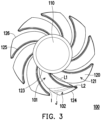
- FIG. 3 is a schematic front view of an impeller in FIG. 2 .
- a fan 10 may be an axial fan and includes a frame 11 and an impeller 100.
- the frame 11 is used for accommodating the impeller 100, in other words, the impeller 100 is disposed in the frame 11 so as to rotate relative to the frame 11 around a rotation axis.
- the frame 11 has an air inlet 11a and an air outlet 11b relative to the air inlet 11a.
- the impeller 100 in operation may introduce airflow from the air inlet 11a in a direction parallel to the rotation axis, and push the airflow outward from the air outlet 11b in the direction parallel to the rotation axis.
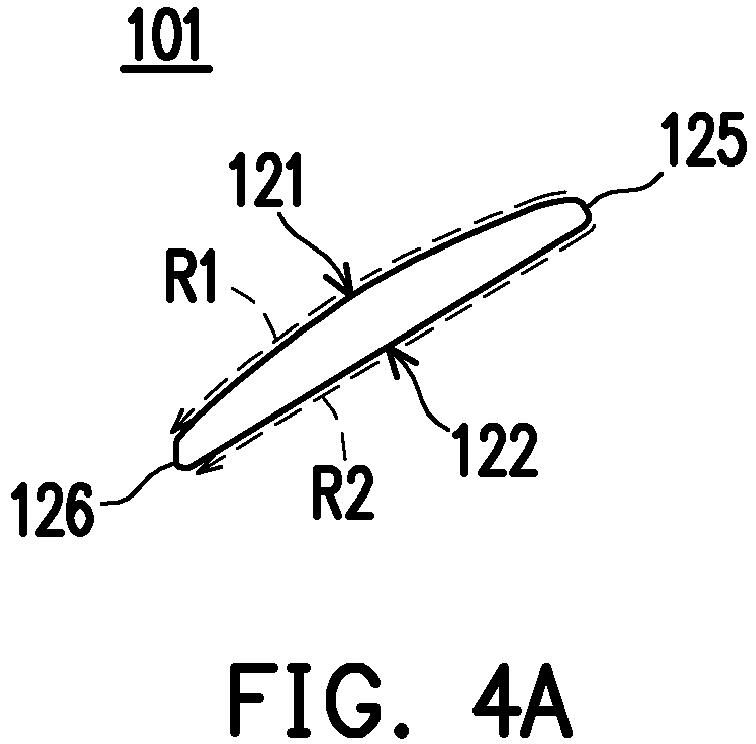
- FIG. 4A and FIG. 4B are schematic views of cross-sectional profiles of a blade along a line segment I and a line segment J in FIG. 3 according to an example.
- the impeller 100 includes a hub 110 and multiple blades 120 surrounding the hub 110, and each blade 120 has a negative pressure surface 121, a positive pressure surface 122 opposite to the negative pressure surface 121, a blade root 123 connected to the hub 110 and a blade tip 124 opposite to the blade root 123.
- the negative pressure surface 121 faces the air inlet 11a
- the positive pressure surface 122 faces the air outlet 11b.
- each blade 120 has at least two different geometric profiles, for example, the geometric profile near the blade root 123 is different from the geometric profile near the blade tip 124.
- each blade 120 may be divided into a first region 101 and a second region 102, where the first region 101 extends from the blade root 123 to the blade tip 124 by a first length L1, and the second region 102 extends from the blade tip 124 to the blade root 123 by a second length L2.
- a geometrical profile (for example, a cross-sectional profile) of each blade 120 in the first region 101 is different from a geometrical profile (for example, a cross-sectional profile) in the second region 102.
- a distance between a border of the first region 101 and the second region 102 and the blade tip 124 is a quarter of a chord length between the blade root 123 and the blade tip 124.
- a distance between the border of the first region 101 and the second region 102 and the blade root 123 is three quarters of the chord length between the blade root 123 and the blade tip 124.
- a sum of the first length L1 and the second length L2 is equal to the chord length between the blade root 123 and the blade tip 124, where the second length L2 is a quarter of the chord length between the blade root 123 and the blade tip 124, and the first length L1 is three quarters of the chord length between the blade root 123 and the blade tip 124.
- the negative pressure surface 121 may be a convex arc surface, and the positive pressure surface 122 may be a plane.
- the flow distance R1 of the airflow on the negative pressure surface 121 is greater than a flow distance R2 of the airflow on the positive pressure surface 122.
- a flow velocity of the airflow on the negative pressure surface 121 is greater than a flow velocity of the airflow on the positive pressure surface 122
- a pressure of the airflow on the negative pressure surface 121 is greater than a pressure of the airflow on the positive pressure surface 122.
- the negative pressure surface 121 may be a convex arc surface
- the positive pressure surface 122 may be a concave arc surface.
- an arc length of the negative pressure surface 121 is close to or equal to an arc length of the positive pressure surface 122
- a flow distance R3 of the airflow on the negative pressure surface 121 is close to or equal to a flow distance R4 of the airflow on the positive pressure surface 122.
- the flow velocity of the airflow on the negative pressure surface 121 is close to or equal to the flow velocity of the airflow on the positive pressure surface 122, and the pressure of the airflow on the negative pressure surface 121 is close to or equal to the pressure of the airflow on the positive pressure surface 122.
- a difference between the flow velocity of the airflow on the negative pressure surface 121 and the flow velocity of the airflow on the positive pressure surface 122 may be close zero or equal to zero, and a difference between the pressure of the airflow on the negative pressure surface 121 and the pressure of the airflow on the positive pressure surface 122 may be close to zero or equal to zero, so as to mitigate a phenomenon that the airflow flows back from the positive pressure surface 122 to the negative pressure surface 121, thereby improving the performance of the fan 10.
- a difference between the flow distance R1 of the airflow on the negative pressure surface 121 and the flow distance R2 on the positive pressure surface 122 in the first region 101 is greater than a difference between the flow distance R3 of the airflow on the negative pressure surface 121 and the flow distance R4 on the positive pressure surface 122 in the second region 102.
- a difference between the flow velocity of the airflow on the negative pressure surface 121 and the flow velocity on the positive pressure surface 122 in the first region 101 is greater than a difference between the flow velocity of the airflow on the negative pressure surface 121 and the flow velocity on the positive pressure surface 122 in the second region 102.
- a difference between the pressure of the airflow on the negative pressure surface 121 and the pressure on the positive pressure surface 122 in the first region 101 is greater than a difference between the pressure of the airflow on the negative pressure surface 121 and the pressure on the positive pressure surface 122 in the second region 102.
- each blade 120 has an air inlet end 125 corresponding to the air inlet 11a and an air outlet end 126 corresponding to the air outlet 11b.
- the airflow flows a first distance (i.e. the flow distance R1) on the negative pressure surface 121 from the air inlet end 125 to the air outlet end 126, and flows a second distance (i.e. the flow distance R2) on the positive pressure surface 122 from the air inlet end 125 to the air outlet end 126.
- the air flow flows a third distance (i.e.
- the first distance i.e., the flow distance R1 is greater than the second distance (i.e., the flow distance R2).
- the second region 102 since an arc length of the negative pressure surface 121 is close to or equal to an arc length of the positive pressure surface 122, the third distance (i.e., the flow distance R3) is close to or equal to the fourth distance (i.e., the flow distance R4). Therefore, the difference between the first distance (i.e., flow distance R1) and the second distance (i.e., flow distance R2) is greater than the difference between the third distance (i.e., flow distance R3) and the fourth distance (i.e., flow distance R4).
- a distance of the airflow flowing from the air inlet end 125 to the air outlet end 126 on the negative pressure surface 121 is close to or equal to a distance of the airflow flowing from the air inlet end 125 to the air outlet end 126 on the positive pressure surface 122.
- the flow velocity of the airflow on the negative pressure surface 121 is close to or equal to the flow velocity on the positive pressure surface 122
- the pressure of the airflow on the negative pressure surface 121 is close to or equal to the pressure on the positive pressure surface 122.
- the pressure difference of the airflow on the negative pressure surface 121 and the positive pressure surface 122 may be close to zero or equal to zero, so as to mitigate the phenomenon that the airflow flows back from the positive pressure surface 122 to the negative pressure surface 121, thereby improving the performance of the fan 10.
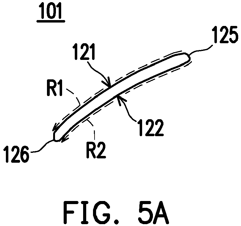
- FIG. 5A and FIG. 5B are schematic views of cross-sectional profiles of a blade along the line segment I and the line segment J in FIG. 3 according to another example.
- a design principle of the example shown in FIG. 5A and FIG. 5B is the same or similar to that of the example shown in FIG. 4A and FIG. 4B , and differences between the two examples will be described below.
- the negative pressure surface 121 and the positive pressure surface 122 are both convex arc surfaces, and the arc length of the negative pressure surface 121 is close to or equal to the arc length of the positive pressure surface 122. Namely, in the second region 102, the flow distance R3 of the airflow on the negative pressure surface 121 is close to or equal to the flow distance R4 on the positive pressure surface 122.
- the flow velocity of the airflow on the negative pressure surface 121 is close to or equal to the flow velocity on the positive pressure surface 122, and the pressure of the airflow on the negative pressure surface 121 is close to or equal to the pressure on the positive pressure surface 122. Therefore, in the second region 102 or in the blade 120 near the blade tip 124, the pressure difference of the airflow on the negative pressure surface 121 and the positive pressure surface 122 may be close to zero or equal to zero, so as to mitigate the phenomenon that the airflow flows back from the positive pressure surface 122 to the negative pressure surface 121, thereby improving the performance of the fan 10.
- the flow distance of the airflow on the negative pressure surface is close to or equal to the flow distance of the airflow on the positive pressure surface, so that the pressure difference of the airflow between the negative pressure surface and the positive pressure surface may be reduced, which mitigate the phenomenon that the airflow flows back from the positive pressure surface to the negative pressure surface, thereby improving the performance of the fan.
Landscapes
- Engineering & Computer Science (AREA)
- Mechanical Engineering (AREA)
- General Engineering & Computer Science (AREA)
- Structures Of Non-Positive Displacement Pumps (AREA)
Abstract

Description
- The invention relates to a fan and an impeller.
- An axial fan introduces airflow in a direction parallel to a rotation axis of an impeller, and pushes the airflow outward in the direction parallel to the rotation axis of the impeller. In detail, the axial fan is composed of the impeller and a frame, and the impeller is disposed in the frame. Limited by capability of a manufacturing process, there is a certain gap (for example, between 0.5mm and 1mm) between a blade tip of a blade and an inner wall of the frame, which is difficult to be further reduced, resulting in a fact that a backflow phenomenon generated at the blade tip of the blade cannot be significantly improved, which affects the performance of the axial fan.
- The invention provides a fan, which has excellent performance.
- The invention provides an impeller, which helps improving performance of a fan.
- The invention provides a fan including a frame and an impeller. The frame has an air inlet and an air outlet opposite to the air inlet. The impeller is disposed in the frame and includes a hub and multiple blades surrounding the hub. Each of the blades has a negative pressure surface facing the air inlet, a positive pressure surface facing the air outlet, a blade root connected to the hub, and a blade tip opposite to the blade root. In a first region extending from the blade root to the blade tip by a first length, the negative pressure surface and the positive pressure surface are respectively a convex arc surface and a plane. In a second region extending from the blade tip to the blade root by a second length smaller than the first length, the negative pressure surface and the positive pressure surface are respectively a convex arc surface and a concave arc surface or both convex arc surfaces. A sum of the first length and the second length is equal to a chord length between the blade root and the blade tip.
- The invention provides an impeller including a hub and multiple blades surrounding the hub. Each of the blades has a negative pressure surface, a positive pressure surface opposite to the negative pressure surface, a blade root connected to the hub, and a blade tip opposite to the blade root. In a first region extending from the blade root to the blade tip by a first length, the negative pressure surface and the positive pressure surface are respectively a convex arc surface and a plane. In a second region extending from the blade tip to the blade root by a second length smaller than the first length, the negative pressure surface and the positive pressure surface are respectively a convex arc surface and a concave arc surface or both convex arc surfaces. A sum of the first length and the second length is equal to a chord length between the blade root and the blade tip.
- Based on the above, by changing a geometric profile of the negative pressure surface and the positive pressure surface near the blade tip in the blade, in the blade near the blade tip, a pressure difference of the airflow between the negative pressure surface and the positive pressure surface may be reduced, which mitigates a phenomenon that the airflow flows back from the positive pressure surface to the negative pressure surface, thereby improving the performance of the fan.
- In order for the aforementioned features and advantages of the disclosure to be more comprehensible, several embodiments accompanied with drawings are described in detail as follows.
-
-
FIG. 1 is a schematic view of a fan according to an embodiment of the invention. -
FIG. 2 is a schematic front view of the fan inFIG. 1 . -
FIG. 3 is a schematic front view of an impeller inFIG. 2 . -
FIG. 4A and FIG. 4B are schematic views of cross-sectional profiles of a blade along a line segment I and a line segment J inFIG. 3 according to an example. -
FIG. 5A and FIG. 5B are schematic views of cross-sectional profiles of a blade along the line segment I and the line segment J inFIG. 3 according to another example. -
FIG. 1 is a schematic view of a fan according to an embodiment of the invention.FIG. 2 is a schematic front view of the fan inFIG. 1 .FIG. 3 is a schematic front view of an impeller inFIG. 2 . Referring toFIG. 1 to FIG. 3 , in the embodiment, afan 10 may be an axial fan and includes aframe 11 and animpeller 100. Theframe 11 is used for accommodating theimpeller 100, in other words, theimpeller 100 is disposed in theframe 11 so as to rotate relative to theframe 11 around a rotation axis. Further, theframe 11 has anair inlet 11a and anair outlet 11b relative to theair inlet 11a. Theimpeller 100 in operation may introduce airflow from theair inlet 11a in a direction parallel to the rotation axis, and push the airflow outward from theair outlet 11b in the direction parallel to the rotation axis. -
FIG. 4A and FIG. 4B are schematic views of cross-sectional profiles of a blade along a line segment I and a line segment J inFIG. 3 according to an example. As shown inFIG. 1 ,FIG. 3 ,FIG. 4A and FIG. 4B , theimpeller 100 includes ahub 110 andmultiple blades 120 surrounding thehub 110, and eachblade 120 has anegative pressure surface 121, apositive pressure surface 122 opposite to thenegative pressure surface 121, ablade root 123 connected to thehub 110 and ablade tip 124 opposite to theblade root 123. In eachblade 120, thenegative pressure surface 121 faces theair inlet 11a, and thepositive pressure surface 122 faces theair outlet 11b. - As shown in
FIG. 3 ,FIG. 4A and FIG. 4B , in the embodiment, eachblade 120 has at least two different geometric profiles, for example, the geometric profile near theblade root 123 is different from the geometric profile near theblade tip 124. Further, eachblade 120 may be divided into afirst region 101 and asecond region 102, where thefirst region 101 extends from theblade root 123 to theblade tip 124 by a first length L1, and thesecond region 102 extends from theblade tip 124 to theblade root 123 by a second length L2. A geometrical profile (for example, a cross-sectional profile) of eachblade 120 in thefirst region 101 is different from a geometrical profile (for example, a cross-sectional profile) in thesecond region 102. - For example, a distance between a border of the
first region 101 and thesecond region 102 and theblade tip 124 is a quarter of a chord length between theblade root 123 and theblade tip 124. On the other hand, a distance between the border of thefirst region 101 and thesecond region 102 and theblade root 123 is three quarters of the chord length between theblade root 123 and theblade tip 124. Namely, a sum of the first length L1 and the second length L2 is equal to the chord length between theblade root 123 and theblade tip 124, where the second length L2 is a quarter of the chord length between theblade root 123 and theblade tip 124, and the first length L1 is three quarters of the chord length between theblade root 123 and theblade tip 124. - As shown in
FIG. 3 andFIG. 4A , in thefirst region 101, thenegative pressure surface 121 may be a convex arc surface, and thepositive pressure surface 122 may be a plane. The flow distance R1 of the airflow on thenegative pressure surface 121 is greater than a flow distance R2 of the airflow on thepositive pressure surface 122. Based on Bernoulli's principle, a flow velocity of the airflow on thenegative pressure surface 121 is greater than a flow velocity of the airflow on thepositive pressure surface 122, and a pressure of the airflow on thenegative pressure surface 121 is greater than a pressure of the airflow on thepositive pressure surface 122. - As shown in
FIG. 3 andFIG. 4B , in thesecond region 102, thenegative pressure surface 121 may be a convex arc surface, and thepositive pressure surface 122 may be a concave arc surface. In detail, since an arc length of thenegative pressure surface 121 is close to or equal to an arc length of thepositive pressure surface 122, a flow distance R3 of the airflow on thenegative pressure surface 121 is close to or equal to a flow distance R4 of the airflow on thepositive pressure surface 122. Based on the Bernoulli's principle, the flow velocity of the airflow on thenegative pressure surface 121 is close to or equal to the flow velocity of the airflow on thepositive pressure surface 122, and the pressure of the airflow on thenegative pressure surface 121 is close to or equal to the pressure of the airflow on thepositive pressure surface 122. Therefore, in thesecond region 102 or in theblade 120 near theblade tip 124, a difference between the flow velocity of the airflow on thenegative pressure surface 121 and the flow velocity of the airflow on thepositive pressure surface 122 may be close zero or equal to zero, and a difference between the pressure of the airflow on thenegative pressure surface 121 and the pressure of the airflow on thepositive pressure surface 122 may be close to zero or equal to zero, so as to mitigate a phenomenon that the airflow flows back from thepositive pressure surface 122 to thenegative pressure surface 121, thereby improving the performance of thefan 10. - In detail, a difference between the flow distance R1 of the airflow on the
negative pressure surface 121 and the flow distance R2 on thepositive pressure surface 122 in thefirst region 101 is greater than a difference between the flow distance R3 of the airflow on thenegative pressure surface 121 and the flow distance R4 on thepositive pressure surface 122 in thesecond region 102. A difference between the flow velocity of the airflow on thenegative pressure surface 121 and the flow velocity on thepositive pressure surface 122 in thefirst region 101 is greater than a difference between the flow velocity of the airflow on thenegative pressure surface 121 and the flow velocity on thepositive pressure surface 122 in thesecond region 102. In addition, a difference between the pressure of the airflow on thenegative pressure surface 121 and the pressure on thepositive pressure surface 122 in thefirst region 101 is greater than a difference between the pressure of the airflow on thenegative pressure surface 121 and the pressure on thepositive pressure surface 122 in thesecond region 102. - As shown in
FIG. 1 ,FIG. 3 ,FIG. 4A and FIG. 4B , eachblade 120 has anair inlet end 125 corresponding to theair inlet 11a and anair outlet end 126 corresponding to theair outlet 11b. In thefirst region 101, the airflow flows a first distance (i.e. the flow distance R1) on thenegative pressure surface 121 from theair inlet end 125 to theair outlet end 126, and flows a second distance (i.e. the flow distance R2) on thepositive pressure surface 122 from theair inlet end 125 to theair outlet end 126. In thesecond region 102, the air flow flows a third distance (i.e. the flow distance R3) on thenegative pressure surface 121 from theair inlet end 125 to theair outlet end 126, and flows a fourth distance (i.e. the flow distance R4) on thepositive pressure surface 122 from theair inlet end 125 to theair outlet end 126. - In the
first region 101, the first distance (i.e., the flow distance R1) is greater than the second distance (i.e., the flow distance R2). In thesecond region 102, since an arc length of thenegative pressure surface 121 is close to or equal to an arc length of thepositive pressure surface 122, the third distance (i.e., the flow distance R3) is close to or equal to the fourth distance (i.e., the flow distance R4). Therefore, the difference between the first distance (i.e., flow distance R1) and the second distance (i.e., flow distance R2) is greater than the difference between the third distance (i.e., flow distance R3) and the fourth distance (i.e., flow distance R4). - In the
second area 102, a distance of the airflow flowing from theair inlet end 125 to theair outlet end 126 on thenegative pressure surface 121 is close to or equal to a distance of the airflow flowing from theair inlet end 125 to theair outlet end 126 on thepositive pressure surface 122. Based on the Bernoulli's principle, the flow velocity of the airflow on thenegative pressure surface 121 is close to or equal to the flow velocity on thepositive pressure surface 122, and the pressure of the airflow on thenegative pressure surface 121 is close to or equal to the pressure on thepositive pressure surface 122. Therefore, in thesecond region 102 or in theblade 120 near theblade tip 124, the pressure difference of the airflow on thenegative pressure surface 121 and thepositive pressure surface 122 may be close to zero or equal to zero, so as to mitigate the phenomenon that the airflow flows back from thepositive pressure surface 122 to thenegative pressure surface 121, thereby improving the performance of thefan 10. -
FIG. 5A and FIG. 5B are schematic views of cross-sectional profiles of a blade along the line segment I and the line segment J inFIG. 3 according to another example. A design principle of the example shown inFIG. 5A and FIG. 5B is the same or similar to that of the example shown inFIG. 4A and FIG. 4B , and differences between the two examples will be described below. - Referring to
FIG. 3 ,FIG. 5A and FIG. 5B , in thesecond region 102, thenegative pressure surface 121 and thepositive pressure surface 122 are both convex arc surfaces, and the arc length of thenegative pressure surface 121 is close to or equal to the arc length of thepositive pressure surface 122. Namely, in thesecond region 102, the flow distance R3 of the airflow on thenegative pressure surface 121 is close to or equal to the flow distance R4 on thepositive pressure surface 122. Based on the Bernoulli's principle, in thesecond region 102, the flow velocity of the airflow on thenegative pressure surface 121 is close to or equal to the flow velocity on thepositive pressure surface 122, and the pressure of the airflow on thenegative pressure surface 121 is close to or equal to the pressure on thepositive pressure surface 122. Therefore, in thesecond region 102 or in theblade 120 near theblade tip 124, the pressure difference of the airflow on thenegative pressure surface 121 and thepositive pressure surface 122 may be close to zero or equal to zero, so as to mitigate the phenomenon that the airflow flows back from thepositive pressure surface 122 to thenegative pressure surface 121, thereby improving the performance of thefan 10. - In summary, by changing a geometric profile of the negative pressure surface and the positive pressure surface near the blade tip in the blade, in the blade near the blade tip, the flow distance of the airflow on the negative pressure surface is close to or equal to the flow distance of the airflow on the positive pressure surface, so that the pressure difference of the airflow between the negative pressure surface and the positive pressure surface may be reduced, which mitigate the phenomenon that the airflow flows back from the positive pressure surface to the negative pressure surface, thereby improving the performance of the fan.
Claims (12)
- A fan, characterized by comprising:a frame (11) having an air inlet (11a) and an air outlet (11b) opposite to the air inlet (11a); andan impeller disposed in the frame (11), and comprising:a hub (110); anda plurality of blades (120) surrounding the hub (110), wherein each of the blades (120) has a negative pressure surface (121) facing the air inlet (11a), a positive pressure surface (122) facing the air outlet (11b), a blade root (123) connected to the hub (110), and a blade tip (124) opposite to the blade root (123), in a first region (101) extending from the blade root (123) to the blade tip by a first length (L1), the negative pressure surface (121) and the positive pressure surface (122) are respectively a convex arc surface and a plane, in a second region (102) extending from the blade tip (124) to the blade root (123) by a second length smaller (L2) than the first length (L1), the negative pressure surface (121) and the positive pressure surface (122) are respectively a convex arc surface and a concave arc surface or both convex arc surfaces, wherein a sum of the first length (L1) and the second length (L2) is equal to a chord length between the blade root (123) and the blade tip (124).
- The fan according to claim 1, characterized in that a difference between a flow velocity of an airflow on the negative pressure surface (121) and a flow velocity on the positive pressure surface (122) in the first region (101) is greater than a difference between a flow velocity of the airflow on the negative pressure surface (121) and a flow velocity on the positive pressure surface (122) in the second region (102).
- The fan according to claim 1, characterized in that a flow velocity of an airflow on the negative pressure surface (121) is greater than a flow velocity on the positive pressure surface (122) in the first region (101), and a flow velocity of the airflow on the negative pressure surface (121) is equal to a flow velocity on the positive pressure surface (122) in the second region (102).
- The fan according to claim 1, characterized in that a difference between a pressure of an airflow on the negative pressure surface (121) and a pressure on the positive pressure surface (122) in the first region (101) is greater than a difference between a pressure of the airflow on the negative pressure surface (121) and a pressure on the positive pressure surface (122) in the second region (102).
- The fan according to claim 1, characterized in that a pressure of an airflow on the negative pressure surface (121) is greater than a pressure on the positive pressure surface (122) in the first region (101), and a pressure of the airflow on the negative pressure surface (121) is equal to a pressure on the positive pressure surface (122) in the second region (102).
- The fan according to claim 1, characterized in that a difference between a flow distance (R1) of an airflow on the negative pressure surface (121) and a flow distance (R2) on the positive pressure surface (122) in the first region (101) is greater than a difference between a flow distance (R3) of the airflow on the negative pressure surface (121) and a flow distance (R4 or R41) on the positive pressure surface (122) in the second region (102).
- The fan according to claim 1, characterized in that a flow distance (R1) of an airflow on the negative pressure surface (121) is greater than a flow distance (R2) on the positive pressure surface (122) in the first region (101), and a flow distance (R3) of the airflow on the negative pressure surface (121) is equal to a flow distance (R4 or R41) on the positive pressure surface (122) in the second region (102).
- The fan according to claim 1, characterized in that each of the blades (120) has an air inlet end (125) corresponding to the air inlet (11a) and an air outlet end (126) corresponding to the air outlet (11b), in the first region (101), an airflow flows a first distance (R1) on the negative pressure surface (121) from the air inlet end (125)to the air outlet end (126), and flows a second distance (R2) on the positive pressure surface (122) from the air inlet end (125) to the air outlet end (126), in the second region (102), the airflow flows a third distance (R3) on the negative pressure surface (121) from the air inlet end (125) to the air outlet end (126), and flows a fourth distance (R4) on the positive pressure surface (122) from the air inlet end (125) to the air outlet end (126), wherein a difference between the first distance (R1) and the second distance (R2) is greater than a difference between the third distance (R3) and the fourth distance (R4).
- The fan according to claim 8, characterized in that the first distance (R1) is greater than the second distance (R2), and the third distance (R3) is equal to the fourth distance (R4).
- The fan according to claim 1, characterized in that the second length is a quarter of the chord length.
- The fan according to claim 1, characterized in that the first length is three quarters of the chord length.
- An impeller (100), characterized by comprising:a hub (110); anda plurality of blades (120) surrounding the hub (110), wherein each of the blades (120) has a negative pressure surface (121), a positive pressure surface (122) opposite to the negative pressure surface (121), a blade root (123) connected to the hub (110), and a blade tip (124) opposite to the blade root (123), in a first region (101) extending from the blade root (123) to the blade tip (124) by a first length, the negative pressure surface (121) and the positive pressure surface (122) are respectively a convex arc surface and a plane, in a second region (102) extending from the blade tip (124) to the blade root (123) by a second length smaller than the first length, the negative pressure surface (121) and the positive pressure surface (122) are respectively a convex arc surface and a concave arc surface or both convex arc surfaces, wherein a sum of the first length and the second length is equal to a chord length between the blade root (123) and the blade tip (124).
Applications Claiming Priority (1)
| Application Number | Priority Date | Filing Date | Title |
|---|---|---|---|
| TW112108250A TWI844293B (en) | 2023-03-07 | 2023-03-07 | Fan and impeller |
Publications (1)
| Publication Number | Publication Date |
|---|---|
| EP4428375A1 true EP4428375A1 (en) | 2024-09-11 |
Family
ID=89384170
Family Applications (1)
| Application Number | Title | Priority Date | Filing Date |
|---|---|---|---|
| EP24161803.2A Pending EP4428375A1 (en) | 2023-03-07 | 2024-03-06 | Fan and impeller |
Country Status (3)
| Country | Link |
|---|---|
| US (1) | US11852158B1 (en) |
| EP (1) | EP4428375A1 (en) |
| TW (1) | TWI844293B (en) |
Families Citing this family (2)
| Publication number | Priority date | Publication date | Assignee | Title |
|---|---|---|---|---|
| TWD214272S (en) * | 2020-12-30 | 2021-09-21 | 大陸商亞浩電子五金塑膠(惠州)有限公司 | Fan impeller |
| CN118128772B (en) * | 2024-03-26 | 2025-01-03 | 浙江铭振电子股份有限公司 | A diagonal flow fan with a pressure stabilizing chamber |
Citations (1)
| Publication number | Priority date | Publication date | Assignee | Title |
|---|---|---|---|---|
| US20200018322A1 (en) * | 2018-07-10 | 2020-01-16 | Hunter Fan Company | Ceiling fan blade |
Family Cites Families (11)
| Publication number | Priority date | Publication date | Assignee | Title |
|---|---|---|---|---|
| US5624234A (en) * | 1994-11-18 | 1997-04-29 | Itt Automotive Electrical Systems, Inc. | Fan blade with curved planform and high-lift airfoil having bulbous leading edge |
| TW482256U (en) * | 1998-09-24 | 2002-04-01 | Sunonwealth Electr Mach Ind Co | Fan with low noise, large quantity of wind and high wind pressure |
| AU2003207098B2 (en) * | 2002-02-28 | 2004-12-23 | Daikin Industries, Ltd. | Fan |
| JP4943817B2 (en) * | 2006-10-31 | 2012-05-30 | 日本電産サーボ株式会社 | Axial fan |
| EP2570677B1 (en) * | 2010-05-13 | 2019-01-23 | Mitsubishi Electric Corporation | Axial flow blower |
| JP6082520B2 (en) * | 2011-12-20 | 2017-02-15 | ミネベアミツミ株式会社 | Impeller used for axial flow fan and axial flow fan using the same |
| DE112014006367B4 (en) * | 2014-02-14 | 2024-08-01 | Mitsubishi Electric Corporation | AXIAL FLOW FANS |
| DE202015100241U1 (en) * | 2014-12-03 | 2015-05-06 | Ebm-Papst Mulfingen Gmbh & Co. Kg | Blade of a fan wheel, fan wheel and axial fan |
| JP5905985B1 (en) * | 2015-08-18 | 2016-04-20 | 山洋電気株式会社 | Axial flow fan and serial type axial flow fan |
| RS66523B1 (en) * | 2019-08-06 | 2025-03-31 | Wuxi Biocity Biopharmaceutics Co Ltd | Crystalline forms of an atr inhibitor and use thereof |
| CN114412835B (en) * | 2022-03-31 | 2022-06-03 | 佛山市南海九洲普惠风机有限公司 | A crescent-shaped non-removable forward and reverse air supply impeller |
-
2023
- 2023-03-07 TW TW112108250A patent/TWI844293B/en active
- 2023-05-03 US US18/311,245 patent/US11852158B1/en active Active
-
2024
- 2024-03-06 EP EP24161803.2A patent/EP4428375A1/en active Pending
Patent Citations (1)
| Publication number | Priority date | Publication date | Assignee | Title |
|---|---|---|---|---|
| US20200018322A1 (en) * | 2018-07-10 | 2020-01-16 | Hunter Fan Company | Ceiling fan blade |
Also Published As
| Publication number | Publication date |
|---|---|
| TW202436765A (en) | 2024-09-16 |
| TWI844293B (en) | 2024-06-01 |
| US11852158B1 (en) | 2023-12-26 |
Similar Documents
| Publication | Publication Date | Title |
|---|---|---|
| US8616843B2 (en) | Turbo machinery | |
| CN102686887B (en) | Cross-flow fans, blowers and air conditioners | |
| CN113309736B (en) | Blade, impeller, centrifugal fan, range hood and blade design method | |
| CN111379737B (en) | Mixed flow impellers, fan components, power systems, fans | |
| JP5351941B2 (en) | Centrifugal compressor, its impeller, its operating method, and impeller design method | |
| US11852158B1 (en) | Fan and impeller | |
| CN111577655B (en) | Blade and axial flow impeller using the same | |
| CN108506247B (en) | Blade and axial flow impeller using same | |
| US7604458B2 (en) | Axial flow pump and diagonal flow pump | |
| CN105221480A (en) | Fan structure | |
| JPH08177792A (en) | Axial fan | |
| CN107313977B (en) | Centrifugal fan blade, centrifugal fan and air conditioner | |
| WO2014128908A1 (en) | Propeller fan and air conditioner equipped with same | |
| CN205876751U (en) | Centrifugal forced draught blower and have air conditioner of this centrifugal forced draught blower | |
| EP4027018A1 (en) | Cross flow fan blade, cross flow fan, and air conditioner indoor unit | |
| US11572890B2 (en) | Blade and axial flow impeller using same | |
| US11536288B2 (en) | Propeller fan | |
| CN110566500A (en) | Impeller of centrifugal ventilator | |
| CN212479687U (en) | Centrifugal impeller, centrifugal fan and refrigeration equipment | |
| TWI775377B (en) | Cooling fan | |
| JP2022130751A (en) | Impeller and centrifugal compressor using the same | |
| US9453512B2 (en) | Cross flow fan, air-sending device, and air-conditioning apparatus | |
| CN109209989B (en) | Centrifugal fan and range hood | |
| CN118855759A (en) | Fan and impeller | |
| CN223782954U (en) | Air conditioner cabinet unit and air conditioner |
Legal Events
| Date | Code | Title | Description |
|---|---|---|---|
| PUAI | Public reference made under article 153(3) epc to a published international application that has entered the european phase |
Free format text: ORIGINAL CODE: 0009012 |
|
| STAA | Information on the status of an ep patent application or granted ep patent |
Free format text: STATUS: THE APPLICATION HAS BEEN PUBLISHED |
|
| AK | Designated contracting states |
Kind code of ref document: A1 Designated state(s): AL AT BE BG CH CY CZ DE DK EE ES FI FR GB GR HR HU IE IS IT LI LT LU LV MC ME MK MT NL NO PL PT RO RS SE SI SK SM TR |
|
| STAA | Information on the status of an ep patent application or granted ep patent |
Free format text: STATUS: REQUEST FOR EXAMINATION WAS MADE |
|
| 17P | Request for examination filed |
Effective date: 20250306 |
|
| GRAP | Despatch of communication of intention to grant a patent |
Free format text: ORIGINAL CODE: EPIDOSNIGR1 |
|
| STAA | Information on the status of an ep patent application or granted ep patent |
Free format text: STATUS: GRANT OF PATENT IS INTENDED |