EP4428332A1 - Adjustable stopper - Google Patents
Adjustable stopper Download PDFInfo
- Publication number
- EP4428332A1 EP4428332A1 EP24153989.9A EP24153989A EP4428332A1 EP 4428332 A1 EP4428332 A1 EP 4428332A1 EP 24153989 A EP24153989 A EP 24153989A EP 4428332 A1 EP4428332 A1 EP 4428332A1
- Authority
- EP
- European Patent Office
- Prior art keywords
- bumper
- lock ring
- sleeve
- core
- base
- Prior art date
- Legal status (The legal status is an assumption and is not a legal conclusion. Google has not performed a legal analysis and makes no representation as to the accuracy of the status listed.)
- Pending
Links
- 238000000034 method Methods 0.000 claims description 13
- 230000002401 inhibitory effect Effects 0.000 claims description 5
- 230000000712 assembly Effects 0.000 description 4
- 238000000429 assembly Methods 0.000 description 4
- 238000004519 manufacturing process Methods 0.000 description 3
- 230000001154 acute effect Effects 0.000 description 1
- 239000013536 elastomeric material Substances 0.000 description 1
- 238000002347 injection Methods 0.000 description 1
- 239000007924 injection Substances 0.000 description 1
- 238000001746 injection moulding Methods 0.000 description 1
- 239000012858 resilient material Substances 0.000 description 1
- 125000006850 spacer group Chemical group 0.000 description 1
Images



Classifications
-
- E—FIXED CONSTRUCTIONS
- E05—LOCKS; KEYS; WINDOW OR DOOR FITTINGS; SAFES
- E05F—DEVICES FOR MOVING WINGS INTO OPEN OR CLOSED POSITION; CHECKS FOR WINGS; WING FITTINGS NOT OTHERWISE PROVIDED FOR, CONCERNED WITH THE FUNCTIONING OF THE WING
- E05F5/00—Braking devices, e.g. checks; Stops; Buffers
- E05F5/02—Braking devices, e.g. checks; Stops; Buffers specially for preventing the slamming of swinging wings during final closing movement, e.g. jamb stops
- E05F5/022—Braking devices, e.g. checks; Stops; Buffers specially for preventing the slamming of swinging wings during final closing movement, e.g. jamb stops specially adapted for vehicles, e.g. for hoods or trunks
-
- E—FIXED CONSTRUCTIONS
- E05—LOCKS; KEYS; WINDOW OR DOOR FITTINGS; SAFES
- E05F—DEVICES FOR MOVING WINGS INTO OPEN OR CLOSED POSITION; CHECKS FOR WINGS; WING FITTINGS NOT OTHERWISE PROVIDED FOR, CONCERNED WITH THE FUNCTIONING OF THE WING
- E05F5/00—Braking devices, e.g. checks; Stops; Buffers
- E05F5/02—Braking devices, e.g. checks; Stops; Buffers specially for preventing the slamming of swinging wings during final closing movement, e.g. jamb stops
- E05F5/022—Braking devices, e.g. checks; Stops; Buffers specially for preventing the slamming of swinging wings during final closing movement, e.g. jamb stops specially adapted for vehicles, e.g. for hoods or trunks
- E05F5/025—Braking devices, e.g. checks; Stops; Buffers specially for preventing the slamming of swinging wings during final closing movement, e.g. jamb stops specially adapted for vehicles, e.g. for hoods or trunks specially adapted for vehicle doors
-
- E—FIXED CONSTRUCTIONS
- E05—LOCKS; KEYS; WINDOW OR DOOR FITTINGS; SAFES
- E05Y—INDEXING SCHEME ASSOCIATED WITH SUBCLASSES E05D AND E05F, RELATING TO CONSTRUCTION ELEMENTS, ELECTRIC CONTROL, POWER SUPPLY, POWER SIGNAL OR TRANSMISSION, USER INTERFACES, MOUNTING OR COUPLING, DETAILS, ACCESSORIES, AUXILIARY OPERATIONS NOT OTHERWISE PROVIDED FOR, APPLICATION THEREOF
- E05Y2600/00—Mounting or coupling arrangements for elements provided for in this subclass
- E05Y2600/10—Adjustable
- E05Y2600/12—Adjustable by manual operation
-
- E—FIXED CONSTRUCTIONS
- E05—LOCKS; KEYS; WINDOW OR DOOR FITTINGS; SAFES
- E05Y—INDEXING SCHEME ASSOCIATED WITH SUBCLASSES E05D AND E05F, RELATING TO CONSTRUCTION ELEMENTS, ELECTRIC CONTROL, POWER SUPPLY, POWER SIGNAL OR TRANSMISSION, USER INTERFACES, MOUNTING OR COUPLING, DETAILS, ACCESSORIES, AUXILIARY OPERATIONS NOT OTHERWISE PROVIDED FOR, APPLICATION THEREOF
- E05Y2600/00—Mounting or coupling arrangements for elements provided for in this subclass
- E05Y2600/10—Adjustable
- E05Y2600/14—Adjustable with position retaining means
-
- E—FIXED CONSTRUCTIONS
- E05—LOCKS; KEYS; WINDOW OR DOOR FITTINGS; SAFES
- E05Y—INDEXING SCHEME ASSOCIATED WITH SUBCLASSES E05D AND E05F, RELATING TO CONSTRUCTION ELEMENTS, ELECTRIC CONTROL, POWER SUPPLY, POWER SIGNAL OR TRANSMISSION, USER INTERFACES, MOUNTING OR COUPLING, DETAILS, ACCESSORIES, AUXILIARY OPERATIONS NOT OTHERWISE PROVIDED FOR, APPLICATION THEREOF
- E05Y2600/00—Mounting or coupling arrangements for elements provided for in this subclass
- E05Y2600/50—Mounting methods; Positioning
- E05Y2600/52—Toolless
- E05Y2600/53—Snapping
-
- E—FIXED CONSTRUCTIONS
- E05—LOCKS; KEYS; WINDOW OR DOOR FITTINGS; SAFES
- E05Y—INDEXING SCHEME ASSOCIATED WITH SUBCLASSES E05D AND E05F, RELATING TO CONSTRUCTION ELEMENTS, ELECTRIC CONTROL, POWER SUPPLY, POWER SIGNAL OR TRANSMISSION, USER INTERFACES, MOUNTING OR COUPLING, DETAILS, ACCESSORIES, AUXILIARY OPERATIONS NOT OTHERWISE PROVIDED FOR, APPLICATION THEREOF
- E05Y2900/00—Application of doors, windows, wings or fittings thereof
- E05Y2900/50—Application of doors, windows, wings or fittings thereof for vehicles
- E05Y2900/53—Type of wing
- E05Y2900/531—Doors
-
- E—FIXED CONSTRUCTIONS
- E05—LOCKS; KEYS; WINDOW OR DOOR FITTINGS; SAFES
- E05Y—INDEXING SCHEME ASSOCIATED WITH SUBCLASSES E05D AND E05F, RELATING TO CONSTRUCTION ELEMENTS, ELECTRIC CONTROL, POWER SUPPLY, POWER SIGNAL OR TRANSMISSION, USER INTERFACES, MOUNTING OR COUPLING, DETAILS, ACCESSORIES, AUXILIARY OPERATIONS NOT OTHERWISE PROVIDED FOR, APPLICATION THEREOF
- E05Y2900/00—Application of doors, windows, wings or fittings thereof
- E05Y2900/50—Application of doors, windows, wings or fittings thereof for vehicles
- E05Y2900/53—Type of wing
- E05Y2900/536—Hoods
-
- E—FIXED CONSTRUCTIONS
- E05—LOCKS; KEYS; WINDOW OR DOOR FITTINGS; SAFES
- E05Y—INDEXING SCHEME ASSOCIATED WITH SUBCLASSES E05D AND E05F, RELATING TO CONSTRUCTION ELEMENTS, ELECTRIC CONTROL, POWER SUPPLY, POWER SIGNAL OR TRANSMISSION, USER INTERFACES, MOUNTING OR COUPLING, DETAILS, ACCESSORIES, AUXILIARY OPERATIONS NOT OTHERWISE PROVIDED FOR, APPLICATION THEREOF
- E05Y2900/00—Application of doors, windows, wings or fittings thereof
- E05Y2900/50—Application of doors, windows, wings or fittings thereof for vehicles
- E05Y2900/53—Type of wing
- E05Y2900/548—Trunk lids
Definitions
- This invention relates generally to an adjustable stopper for a vehicle. More specifically, although not exclusively, this invention relates to adjustable stopper assemblies for vehicles, for keeping two structural parts of a vehicle in a spaced relationship with each other and/or to prevent damage.
- Stopper assemblies are commonly used in the automotive sector.
- adjustable stopper assemblies are used to withstand and reduce the vibrations of parts which may be opened, such as the hood of the engine compartment or the trunk door.
- Stopper assemblies have the function of supporting a movable structural part (for example the hood or trunk door of a vehicle) in a position flush with a stationary structural part (for example the body of a vehicle).
- the relative distance between the two structural parts may vary, for example, owing to manufacturing and assembly tolerances. There is therefore a need to have an improved adjustable spacer devices which allow compensation of the manufacturing and assembly tolerances between the two structural parts.
- a first aspect of the invention provides an adjustable stopper assembly, e.g. for a vehicle door or hood, the assembly comprising a base for mounting the assembly to a vehicle, a bumper movable relative to the base and a lock ring rotatable to inhibit movement of the bumper toward the base.
- a rotatable lock ring for inhibiting movement of the bumper enables simple and effective positioning of the bumper to compensate for manufacturing and assembly tolerances.
- the bumper may be mounted to the base, for example by an adjustment means.
- the lock ring may be operable by rotation.
- the lock ring may comprise an unlocked condition, e.g. in which the bumper is movable toward the base.
- the lock ring may comprise a locked condition, e.g. in which movement of the bumper toward the base is inhibited.
- the lock ring may be operable or rotatable between the unlocked and locked conditions.
- an adjustable stopper assembly e.g. for a vehicle door or hood, the assembly comprising a base for mounting the assembly to a vehicle, a bumper mounted to the base and a lock ring rotatable between an unlocked condition, in which the bumper is movable toward the base, and a locked condition, in which movement of the bumper toward the base is inhibited.
- the assembly may comprise lock means, which may include the lock ring.
- the lock means may be operable between the or an unlocked condition and the or a locked condition.
- the adjustment means may be operable or adjustable when the lock means or lock ring is in the unlocked condition.
- the adjustment means may be locked, blocked, inoperable or non-adjustable when the lock means or lock ring is in the locked condition.
- an adjustable stopper assembly e.g. for a vehicle door or hood, the assembly comprising: a base for mounting the assembly to a vehicle; a bumper mounted to the base by an adjustment means; and lock means operable between an unlocked condition, in which the bumper is movable toward the base, and a locked condition, in which the adjustment means is locked, blocked, inoperable or non-adjustable to inhibit movement of the bumper toward the base.
- the adjustment means may comprise an adjustment mechanism.
- the assembly or adjustment means may comprise a core.
- the core may project from the base.
- the assembly or adjustment means may comprise a sleeve, which may surround the core.
- the sleeve may be between or located between the bumper and the base.
- the bumper may be mounted to the base by a sleeve.
- the bumper may be movable along the core, e.g. when the lock means or lock ring is in the unlocked condition.
- the sleeve may clamp the core, for example to inhibit movement of the bumper along the core and/or when the lock means or lock ring is in the locked condition.
- an adjustable stopper assembly e.g. for a vehicle door or hood, the assembly comprising: a base for mounting the assembly to a vehicle; a core projecting from the base; a bumper mounted to the base by a sleeve that surrounds the core; and lock means operable between an unlocked condition, in which the bumper is movable along the core, and a locked condition, in which the sleeve clamps the core to inhibit movement of the bumper along the core.
- the sleeve may comprise an arm, which may be resilient and/or be resiliently deformable or movable and/or be formed of a resilient material.
- the arm may be movable into engagement with the core, for example when the lock means or lock ring is operated or rotated, e.g. from the unlocked condition to the locked condition
- the lock ring may surround the sleeve.
- the lock ring may comprise a cam, e.g. an inner cam.
- the lock ring may be operable by rotation to cause the cam to urge the arm into engagement with the core. Rotation of the lock ring may cause the cam to urge the arm into engagement with the core, for example when the lock means or lock ring is operated or rotated from the unlocked condition to the locked condition.
- the cam of the lock ring may comprise or be provided by a non-round surface, which may be or comprise an inner surface.
- the non-round surface may engage the arm, for example on operation or rotation of the lock means or lock ring, e.g. relative to the sleeve.
- the arm may be one of two or more arms, e.g. a pair of opposed arms, which may be resilient.
- the cam may be one of two or more, e.g. a pair of, cams. Each cam may urge a respective one of the arms, e.g. into engagement with the core.
- the further cam(s) may include one or more features of the aforementioned cam.
- the pair of arms may be movable into engagement with the core, for example when the lock means or lock ring is operated or rotated from the unlocked condition to the locked condition. Operation or rotation of the lock means or lock ring from the unlocked condition to the locked condition may cause the pair of arms to clamp the core, e.g. therebetween.
- the core may comprise a gripping feature.
- the sleeve may comprise a gripping feature.
- the or at least one or each gripping feature may comprise one or more teeth, ridges or serrations.
- the gripping feature of the core may be for cooperation with the or a corresponding gripping feature of the sleeve, for example to inhibit movement of the sleeve along the core, such as when the lock means or lock ring is in the locked condition.
- the lock means or lock ring may be operable or rotatable by hand and/or without tools or with no tools.
- the lock means or lock ring may be accessible, e.g. by a user, when the bumper is in contact with the vehicle door or hood.
- the lock means or lock ring may be located or positioned between the bumper, or an end or free end of the bumper, and the base or a mounting end of the base.
- the bumper may be threadedly connected to the sleeve, e.g. for further adjusting or fine tune adjusting its position relative to the base.
- the bumper may comprise a thread, which may comprise an internal thread.
- the sleeve may comprise a thread, which may comprise an external thread.
- the thread of the bumper may be cooperable or configured to cooperate with the thread of the sleeve, for example to adjust the position of the bumper relative to the sleeve and/or relative to the base, e.g. when the lock means or lock ring is in the locked condition.
- the threaded connection between the bumper and the sleeve may be for further adjusting or fine tune adjusting the position of the bumper relative to the sleeve and/or the base.
- the bumper or the end or free end of the bumper, may comprise a closed end.
- the end, free end or closed end may be for cooperating with the vehicle door or hood.
- the bumper may comprise an indicator, e.g. for indicating a rotational position thereof relative to the base.
- the indicator may be at, on or adjacent the end, free end or closed end of the bumper.
- the lock means or lock ring may surround the bumper.
- the lock means or lock ring may surround the sleeve.
- the lock means or lock ring may comprise at least one stop, for example first and second stops.
- the bumper may comprise a stop.
- the sleeve may comprise a stop.
- the stop or first stop of the lock means or lock ring may cooperate, or may be for cooperating, with the stop of the bumper.
- the stop or second stop of the lock means or lock ring may cooperate, or may be for cooperating, with the stop of the sleeve. Cooperation of the stops may retain the bumper on the sleeve.
- the first stop of the lock means or lock ring cooperates, or is for cooperating, with the stop of the bumper and the second stop of the lock means or lock ring cooperates, or is for cooperating, with the stop of the sleeve, thereby to retain the bumper on the sleeve.
- the assembly may comprise one or more, e.g. a plurality of, catch features. At least one or some of the catch features may be between the lock ring and the bumper, e.g. for providing a step-wise threaded adjustment of the bumper relative to the sleeve. At least one or some of the catch features may be between the sleeve and the lock ring, e.g. for inhibiting rotation of the lock ring out of at least one of the locked and unlocked conditions.
- the sleeve may comprise a receptacle or passage, e.g. a core receptacle or passage.
- the receptacle or passage may receive the core or may be for receiving the core.
- the core may comprise a non-round shape.
- the receptacle or passage may comprise a non-round shape, which may be complimentary to or cooperable with the non-round shape of the core.
- the non-round shapes of the core and receptacle or passage may have a cooperating non-round shape.
- the non-round shape of one or each of the core and receptacle or passage, or the cooperation therebetween may be for inhibiting or may inhibit relative rotation therebetween.
- the method may comprise closing a door or hood, e.g. of the vehicle.
- the door or hood may be closed to cause the or a bumper of the assembly to move toward the or a base to which it is mounted, e.g. adjustably mounted.
- the bumper may be mounted to the base by an adjustment means.
- the method may comprise operating a lock means or rotating a lock ring, for example to lock the adjustment means and/or to inhibit movement of the bumper relative to the base.
- Another aspect of the invention provides a method of adjusting a stopper assembly, e.g. a vehicle door or hood stopper assembly, the method comprising closing a door or hood to cause a bumper of the assembly to move toward a base to which it is adjustably mounted by an adjustment means and rotating a lock ring to lock the adjustment means to inhibit movement of the bumper relative to the base.
- a stopper assembly e.g. a vehicle door or hood stopper assembly
- the method may comprise operating or operating the lock means or rotating a lock ring from an unlocked condition, e.g. in which the bumper is movable toward the base, to a locked condition, e.g. in which movement of the bumper toward the base is inhibited.
- Movement of the bumper toward or relative to the base may comprise movement of the bumper along a core, which may project from the base.
- the core may comprise part of the adjustment means. Operation of the lock means or rotation of the lock ring may cause a sleeve, e.g. of the adjustment means, to clamp the core, for example to inhibit movement of the bumper along the core and/or when the lock means is operated or lock ring is rotated to the locked condition.
- Clamping of the sleeve to the core may comprise moving, deforming or displacing, e.g. resiliently, an arm of the sleeve toward the core.
- the arm may be one of a pair of opposed arms, which may be resilient.
- Clamping of the sleeve to the core may comprise moving, deforming or displacing, e.g. resiliently, the or a pair of arms of the sleeve toward the core, thereby to cause the pair of arms to clamp the core, e.g. therebetween.
- the arm(s) may be moved into engagement with the core, for example when the lock means or lock ring is operated or rotated, e.g. from the unlocked condition to the locked condition
- Operation of the lock means or rotation of the lock ring may cause a cam, e.g. an inner cam, thereof to urge the arm(s) into engagement with the core.
- Rotation of the lock ring may cause the cam to urge the arm(s) into engagement with the core, for example when the lock means is operated or the lock ring is rotated from the unlocked condition to the locked condition.
- Rotation of the lock ring may cause a non-round surface, e.g. an inner non-round surface, of the cam to urge the arm(s) into engagement with the core, for example when the lock means is operated or the lock ring is rotated from the unlocked condition to the locked condition.
- Engagement of the arm(s) with the core may comprise cooperation between gripping features of each of the arm(s) and the core, for example to inhibit movement of the sleeve along the core, such as when the lock means or lock ring is in the locked condition.
- the method may comprise operating the lock means or rotating the lock means or lock ring by hand and/or without tools or with no tools. Rotation of the lock means or lock ring into or out of one or each of the locked and/or unlocked conditions may be inhibited by one or more, e.g. a plurality of, catch features that may be between the lock means or lock ring and the sleeve.
- the method may comprise rotating the bumper relative to the sleeve, for example thereby to further adjust or fine tune adjust the position of the bumper relative to the base, e.g. via a threaded connection therebetween.
- Rotation of the bumper may comprise step-wise adjustment, which may be enabled or facilitated by one or more, e.g. a plurality of, catch features that may be between the bumper and the lock means, lock ring or sleeve.
- the adjustable stopper assembly may comprise any one or more features of the method relevant thereto and/or the method may comprise any one or more features or steps relevant to one or more features of the adjustable stopper assembly.
- the adjustable stopper assembly according to any one aspect may include one or more features described in relation to any other aspect.
- an adjustable stopper assembly 1 for a vehicle door or hood (not shown).
- the assembly includes a base 2 for mounting the assembly to a vehicle, a bumper 3 mounted to the base 2 and a lock ring 4 rotatable between an unlocked condition, in which the bumper 3 is movable toward the base 2, and a locked condition, in which movement of the bumper 3 toward the base 2 is inhibited.
- a core 20 projects from the base 2 and a sleeve 5 surrounds the core 20 and is received between the bumper 3 and the base 2.
- the core 20 is non-round, having a square cross-section in this example.
- Each of a pair of opposed sides of the core 20 includes a series of outwardly projecting serrated teeth 21, which provide gripping features that will be discussed further below.
- the base 2 has a generally obround mounting portion 22 with a pair of holes 23 through its thickness for receiving fasteners (not shown) that secure the base 2, and therefore the entire assembly 1, to a vehicle body (not shown).
- the base 2 also has a cylindrical receptacle 24 projecting from the mounting portion 22 at an acute angle.
- the core 20 is located within the cylindrical receptacle 24 and is coaxial therewith.
- the bumper 3 is generally cylindrical in shape, with a radial flange 30 at one of its ends.
- the radial flange 30 includes a plurality of shallow depressions 31 spread equally about its periphery.
- the bumper 3 also includes a closed end 32 with a circular central recess 33 to accommodate an injection point required for injection moulding the bumper 3.
- the radial flange 30 is located at the opposite end of the bumper, which is open to provide access to a female thread 34 within the bumper 3.
- the radial flange 30 and female thread 34 are provided by a separate component that is overmoulded with an elastomeric material to provide a resilient bumper 3 against which the vehicle door or hood is to abut.
- FIG. 6 shows an alternative bumper 3', which is similar to the bumper 3 shown in Figures 1 to 5 , wherein like features are labelled with like features followed by a '.
- the bumper 3' shown in Figure 6 differs from that of Figures 1 to 5 only in that it includes an elongated recess 33' in place of the circular central recess 33.
- the elongated recess 33' originates at the centre of the closed end 32' and extends radially outwardly. This elongated recess 33' provides an indication of the radial position of the bumper 3', which is useful when making final adjustments to the position of the bumper 3' as described further below.
- FIGS 7 to 9 illustrate more clearly the lock ring 4, which is generally cylindrical and includes a first ring portion 40a received within the cylindrical receptacle 24 of the base 2 and a second ring portion 40b surrounding the bumper 3.
- the lock ring 4 also includes a pair of cams 41 at the junction between the first and second ring portions 40a, 40b.
- An inner cam surface 42 is formed by the cams 41.
- the inner cam surface 42 is non-round, in this case elliptical.
- a series of inwardly projecting first stops 43 are provided by respective barbed ends of three resilient arms 43a described in the second ring portion 40b.
- a series of inwardly projecting second stops 44 at are also provided by respective barbed ends of two resilient arms 44a described in the first ring portion 40a, thereby providing inwardly projecting stops 43, 44 at each end of the lock ring 4.
- a plurality of inwardly extending axial ridges 45 are spaced about an inner surface of the second ring portion 40b.
- a plurality of axial depressions 46 are spaced about an inner surface of the first ring portion 40a.
- the sleeve 5 is generally cylindrical with a pair of opposed resilient arms 50 each having an outwardly projecting cam 50a and a series of inwardly projecting serrated teeth 51 adjacent its free end.
- the sleeve 5 also has a pair of part-annular recessed stops 52 adjacent a first of its ends that receive and engage with the inwardly projecting second stops 44 of the lock ring 4.
- the stops 52 of the sleeve 5 and the second stops 44 of the lock ring 4 include cooperating frustoconical surfaces 44b, 52a.
- the sleeve 5 is inserted into the lock ring 4, and so the frustoconical surfaces 44b of the second stops 44 of the lock ring 4 provide a lead-in for urging the resilient arms 44a apart until the second stops 44 snap into engagement with the recessed stops 52 of the sleeve 5.
- the sleeve 5 is tubular, but while it is substantially cylindrical externally, the sleeve 5 includes a core receptacle 53 having a non-round cross-section, square in this example, to receive the correspondingly shaped core 20. Externally, the sleeve 5 includes a plurality of axial ridges 54 spaced equally about its periphery. The axial ridges 54 are configured to be received within the axial depressions 46 of the lock ring 4, thereby to inhibit rotation of the lock ring 4 relative to the sleeve 5.
- the sleeve 5 also includes a male thread 55 at the second of its ends, for cooperation with the female thread 34 of the bumper 3.
- the core 20 of the base 2 is received within the core receptacle 53 of the sleeve 5, which itself is received within the lock ring 4 and first ring portion 40a of the lock ring 4 is received within the cylindrical receptacle 24 of the base 2.
- the bumper 3 is received within the second ring portion 40b of the lock ring 4 and the female thread 34 of the bumper 3 engage the male thread 55 of the sleeve 5.
- the first stops 43 of the lock ring 4 cooperate with the radial flange 30 of the bumper 3 to prevent the bumper 3 from being removed from the assembly 1.
- the lock ring 4 is rotatable to cause the cams 41 thereof to engage the cams 50a of the resilient arms 50, thereby to clamp the core 20 between the resilient arms 50. More specifically, the resilient arms 50 of the sleeve 5 are oriented at 90° relative to the cams 41 of the lock ring 4 when the lock ring 4 is in the unlocked condition. In this condition, the resilient arms 50 are relaxed, as shown in Figures 10 and 11 . In the locked condition, the cams 41 of the lock ring 4 engage the cams 50a of the resilient arms 50 such that the core 20 is clamped between the resilient arms 50, as shown in Figure 3 .
- the axial ridges 54 of the sleeve 5 engage with the axial depressions 46 of the lock ring 4 when the lock ring 4 is in each of the locked and unlocked condition. As a result, these catch features 54, 46 inhibit rotation of the lock ring 4 out of each of the locked and unlocked conditions.
- the sleeve 5 When the lock ring 4 is in the unlocked condition, however, the sleeve 5 is able to slide along the core 20, and thereby move toward or away from the base 2. In this, unlocked condition, it is preferable that there is some engagement between the serrated teeth 21, 51, but where an axial force applied to the sleeve 5 causes the resilient arms 50 to flex slightly outwardly to allow the serrated teeth 21, 51 to disengage and reengage. This provides a step-wise adjustment of the sleeve 5 along the core 20.
- the threaded engagement between the bumper 3 and the sleeve 5 enables a fine-tune adjustment of the position of the bumper 3 relative to the base 2 when the sleeve 5 is secured in position to the base 2.
- the depressions 31 of the bumper 3 engage the ridges 45 of the lock ring 4 as the bumper 3 is rotated relative to the sleeve 5.
- These catch features 31, 45 provide an audible clicking sound, which facilitates step-wise adjustment of the bumper 3 relative to the sleeve 5.
- the stopper assembly 1 is mounted to the vehicle and the lock ring 4 is placed in the unlocked condition.
- the door or hood is then closed against the bumper 3 to urge the bumper 3 toward a base 2.
- This force pushes the sleeve 5 along the core 20 to a position that corresponds largely to that which is appropriate for the vehicle.
- the door or hood is then be opened and the lock ring 4 is rotated from the unlocked condition to the locked condition. This prevents movement of the sleeve 5 relative to the base 2, thereby inhibiting movement of the bumper 3 relative to the base.
- the elongated recess 33' of the bumper 3' of Figure 6 provides an indication of its radial position, which may be advantageous when carrying out this fine tune adjustment.
- the skilled person will also appreciate from the aforementioned disclosure that the lock ring 4 and bumper 3, 3' are advantageously operable by hand with no tools.
Landscapes
- Lock And Its Accessories (AREA)
Abstract
The invention relates to an adjustable stopper assembly (1) for a vehicle door or hood. The assembly includes a base (2) for mounting the assembly to a vehicle, a core (3) projecting from the base (2), a bumper (4, 4') mounted to the base (2) by a sleeve (5) that surrounds the core (3) and lock means (6). The lock means (6) includes a lock ring (60) rotatable between locked and unlocked conditions. In the unlocked condition, the bumper (4, 4') is movable along the core (3). In the locked condition, the sleeve (5) clamps the core (3) to inhibit movement of the bumper (4, 4') along the core (3).
Description
- This invention relates generally to an adjustable stopper for a vehicle. More specifically, although not exclusively, this invention relates to adjustable stopper assemblies for vehicles, for keeping two structural parts of a vehicle in a spaced relationship with each other and/or to prevent damage.
- Stopper assemblies are commonly used in the automotive sector. In particular, adjustable stopper assemblies are used to withstand and reduce the vibrations of parts which may be opened, such as the hood of the engine compartment or the trunk door.
- Stopper assemblies have the function of supporting a movable structural part (for example the hood or trunk door of a vehicle) in a position flush with a stationary structural part (for example the body of a vehicle). The relative distance between the two structural parts may vary, for example, owing to manufacturing and assembly tolerances. There is therefore a need to have an improved adjustable spacer devices which allow compensation of the manufacturing and assembly tolerances between the two structural parts.
- A first aspect of the invention provides an adjustable stopper assembly, e.g. for a vehicle door or hood, the assembly comprising a base for mounting the assembly to a vehicle, a bumper movable relative to the base and a lock ring rotatable to inhibit movement of the bumper toward the base.
- The provision of a rotatable lock ring for inhibiting movement of the bumper enables simple and effective positioning of the bumper to compensate for manufacturing and assembly tolerances.
- The bumper may be mounted to the base, for example by an adjustment means. The lock ring may be operable by rotation. The lock ring may comprise an unlocked condition, e.g. in which the bumper is movable toward the base. The lock ring may comprise a locked condition, e.g. in which movement of the bumper toward the base is inhibited. The lock ring may be operable or rotatable between the unlocked and locked conditions.
- Another aspect of the invention provides an adjustable stopper assembly, e.g. for a vehicle door or hood, the assembly comprising a base for mounting the assembly to a vehicle, a bumper mounted to the base and a lock ring rotatable between an unlocked condition, in which the bumper is movable toward the base, and a locked condition, in which movement of the bumper toward the base is inhibited.
- The assembly may comprise lock means, which may include the lock ring. The lock means may be operable between the or an unlocked condition and the or a locked condition.
- The adjustment means may be operable or adjustable when the lock means or lock ring is in the unlocked condition. The adjustment means may be locked, blocked, inoperable or non-adjustable when the lock means or lock ring is in the locked condition.
- Another aspect of the invention provides an adjustable stopper assembly, e.g. for a vehicle door or hood, the assembly comprising: a base for mounting the assembly to a vehicle; a bumper mounted to the base by an adjustment means; and lock means operable between an unlocked condition, in which the bumper is movable toward the base, and a locked condition, in which the adjustment means is locked, blocked, inoperable or non-adjustable to inhibit movement of the bumper toward the base.
- The adjustment means may comprise an adjustment mechanism. The assembly or adjustment means may comprise a core. The core may project from the base. The assembly or adjustment means may comprise a sleeve, which may surround the core. The sleeve may be between or located between the bumper and the base. The bumper may be mounted to the base by a sleeve.
- The bumper may be movable along the core, e.g. when the lock means or lock ring is in the unlocked condition. The sleeve may clamp the core, for example to inhibit movement of the bumper along the core and/or when the lock means or lock ring is in the locked condition.
- Another aspect of the invention provides an adjustable stopper assembly, e.g. for a vehicle door or hood, the assembly comprising: a base for mounting the assembly to a vehicle; a core projecting from the base; a bumper mounted to the base by a sleeve that surrounds the core; and lock means operable between an unlocked condition, in which the bumper is movable along the core, and a locked condition, in which the sleeve clamps the core to inhibit movement of the bumper along the core.
- The sleeve may comprise an arm, which may be resilient and/or be resiliently deformable or movable and/or be formed of a resilient material. The arm may be movable into engagement with the core, for example when the lock means or lock ring is operated or rotated, e.g. from the unlocked condition to the locked condition
- The lock ring may surround the sleeve. The lock ring may comprise a cam, e.g. an inner cam. The lock ring may be operable by rotation to cause the cam to urge the arm into engagement with the core. Rotation of the lock ring may cause the cam to urge the arm into engagement with the core, for example when the lock means or lock ring is operated or rotated from the unlocked condition to the locked condition.
- The cam of the lock ring may comprise or be provided by a non-round surface, which may be or comprise an inner surface. The non-round surface may engage the arm, for example on operation or rotation of the lock means or lock ring, e.g. relative to the sleeve.
- The arm may be one of two or more arms, e.g. a pair of opposed arms, which may be resilient. The cam may be one of two or more, e.g. a pair of, cams. Each cam may urge a respective one of the arms, e.g. into engagement with the core. The further cam(s) may include one or more features of the aforementioned cam.
- The pair of arms may be movable into engagement with the core, for example when the lock means or lock ring is operated or rotated from the unlocked condition to the locked condition. Operation or rotation of the lock means or lock ring from the unlocked condition to the locked condition may cause the pair of arms to clamp the core, e.g. therebetween.
- The core may comprise a gripping feature. The sleeve may comprise a gripping feature. The or at least one or each gripping feature may comprise one or more teeth, ridges or serrations. The gripping feature of the core may be for cooperation with the or a corresponding gripping feature of the sleeve, for example to inhibit movement of the sleeve along the core, such as when the lock means or lock ring is in the locked condition.
- The lock means or lock ring may be operable or rotatable by hand and/or without tools or with no tools. The lock means or lock ring may be accessible, e.g. by a user, when the bumper is in contact with the vehicle door or hood. The lock means or lock ring may be located or positioned between the bumper, or an end or free end of the bumper, and the base or a mounting end of the base.
- The bumper may be threadedly connected to the sleeve, e.g. for further adjusting or fine tune adjusting its position relative to the base. The bumper may comprise a thread, which may comprise an internal thread. The sleeve may comprise a thread, which may comprise an external thread. The thread of the bumper may be cooperable or configured to cooperate with the thread of the sleeve, for example to adjust the position of the bumper relative to the sleeve and/or relative to the base, e.g. when the lock means or lock ring is in the locked condition. The threaded connection between the bumper and the sleeve may be for further adjusting or fine tune adjusting the position of the bumper relative to the sleeve and/or the base.
- The bumper, or the end or free end of the bumper, may comprise a closed end. The end, free end or closed end may be for cooperating with the vehicle door or hood. The bumper may comprise an indicator, e.g. for indicating a rotational position thereof relative to the base. The indicator may be at, on or adjacent the end, free end or closed end of the bumper.
- The lock means or lock ring may surround the bumper. The lock means or lock ring may surround the sleeve. The lock means or lock ring may comprise at least one stop, for example first and second stops. The bumper may comprise a stop. The sleeve may comprise a stop.
- The stop or first stop of the lock means or lock ring may cooperate, or may be for cooperating, with the stop of the bumper. The stop or second stop of the lock means or lock ring may cooperate, or may be for cooperating, with the stop of the sleeve. Cooperation of the stops may retain the bumper on the sleeve.
- In some examples, the first stop of the lock means or lock ring cooperates, or is for cooperating, with the stop of the bumper and the second stop of the lock means or lock ring cooperates, or is for cooperating, with the stop of the sleeve, thereby to retain the bumper on the sleeve.
- The assembly may comprise one or more, e.g. a plurality of, catch features. At least one or some of the catch features may be between the lock ring and the bumper, e.g. for providing a step-wise threaded adjustment of the bumper relative to the sleeve. At least one or some of the catch features may be between the sleeve and the lock ring, e.g. for inhibiting rotation of the lock ring out of at least one of the locked and unlocked conditions.
- The sleeve may comprise a receptacle or passage, e.g. a core receptacle or passage. The receptacle or passage may receive the core or may be for receiving the core. The core may comprise a non-round shape. The receptacle or passage may comprise a non-round shape, which may be complimentary to or cooperable with the non-round shape of the core. The non-round shapes of the core and receptacle or passage may have a cooperating non-round shape. The non-round shape of one or each of the core and receptacle or passage, or the cooperation therebetween, may be for inhibiting or may inhibit relative rotation therebetween.
- Another aspect of the invention provides a method of adjusting a stopper assembly, e.g. a vehicle door or hood stopper assembly. The assembly may comprise one or more features of the assembly described above.
- The method may comprise closing a door or hood, e.g. of the vehicle. The door or hood may be closed to cause the or a bumper of the assembly to move toward the or a base to which it is mounted, e.g. adjustably mounted. The bumper may be mounted to the base by an adjustment means. The method may comprise operating a lock means or rotating a lock ring, for example to lock the adjustment means and/or to inhibit movement of the bumper relative to the base.
- Another aspect of the invention provides a method of adjusting a stopper assembly, e.g. a vehicle door or hood stopper assembly, the method comprising closing a door or hood to cause a bumper of the assembly to move toward a base to which it is adjustably mounted by an adjustment means and rotating a lock ring to lock the adjustment means to inhibit movement of the bumper relative to the base.
- The method may comprise operating or operating the lock means or rotating a lock ring from an unlocked condition, e.g. in which the bumper is movable toward the base, to a locked condition, e.g. in which movement of the bumper toward the base is inhibited.
- Movement of the bumper toward or relative to the base may comprise movement of the bumper along a core, which may project from the base. The core may comprise part of the adjustment means. Operation of the lock means or rotation of the lock ring may cause a sleeve, e.g. of the adjustment means, to clamp the core, for example to inhibit movement of the bumper along the core and/or when the lock means is operated or lock ring is rotated to the locked condition.
- Clamping of the sleeve to the core may comprise moving, deforming or displacing, e.g. resiliently, an arm of the sleeve toward the core. The arm may be one of a pair of opposed arms, which may be resilient. Clamping of the sleeve to the core may comprise moving, deforming or displacing, e.g. resiliently, the or a pair of arms of the sleeve toward the core, thereby to cause the pair of arms to clamp the core, e.g. therebetween. The arm(s) may be moved into engagement with the core, for example when the lock means or lock ring is operated or rotated, e.g. from the unlocked condition to the locked condition
- Operation of the lock means or rotation of the lock ring may cause a cam, e.g. an inner cam, thereof to urge the arm(s) into engagement with the core. Rotation of the lock ring may cause the cam to urge the arm(s) into engagement with the core, for example when the lock means is operated or the lock ring is rotated from the unlocked condition to the locked condition. Rotation of the lock ring may cause a non-round surface, e.g. an inner non-round surface, of the cam to urge the arm(s) into engagement with the core, for example when the lock means is operated or the lock ring is rotated from the unlocked condition to the locked condition.
- Engagement of the arm(s) with the core may comprise cooperation between gripping features of each of the arm(s) and the core, for example to inhibit movement of the sleeve along the core, such as when the lock means or lock ring is in the locked condition.
- The method may comprise operating the lock means or rotating the lock means or lock ring by hand and/or without tools or with no tools. Rotation of the lock means or lock ring into or out of one or each of the locked and/or unlocked conditions may be inhibited by one or more, e.g. a plurality of, catch features that may be between the lock means or lock ring and the sleeve.
- The method may comprise rotating the bumper relative to the sleeve, for example thereby to further adjust or fine tune adjust the position of the bumper relative to the base, e.g. via a threaded connection therebetween. Rotation of the bumper may comprise step-wise adjustment, which may be enabled or facilitated by one or more, e.g. a plurality of, catch features that may be between the bumper and the lock means, lock ring or sleeve.
- For the avoidance of doubt, any of the features described herein apply equally to any aspect of the invention. For example, the adjustable stopper assembly may comprise any one or more features of the method relevant thereto and/or the method may comprise any one or more features or steps relevant to one or more features of the adjustable stopper assembly. Equally, the adjustable stopper assembly according to any one aspect may include one or more features described in relation to any other aspect.
- Within the scope of this application it is expressly intended that the various aspects, embodiments, examples and alternatives set out in the preceding paragraphs, in the claims and/or in the following description and drawings, and in particular the individual features thereof, may be taken independently or in any combination.
- All embodiments and/or features of any embodiment can be combined in any way and/or combination, unless such features are incompatible. For the avoidance of doubt, the terms "may", "and/or", "e.g.", "for example" and any similar term as used herein should be interpreted as non-limiting such that any feature so-described need not be present.
- Indeed, any combination of optional features is expressly envisaged without departing from the scope of the invention, whether or not these are expressly claimed. The applicant reserves the right to change any originally filed claim or file any new claim accordingly, including the right to amend any originally filed claim to depend from and/or incorporate any feature of any other claim although not originally claimed in that manner.
- Embodiments of the invention will now be described by way of example only with reference to the accompanying drawings in which:
-
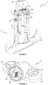
Figure 1 is an upper perspective view of an adjustable stopper assembly; -
Figure 2 is a lower perspective view of the assembly ofFigure 1 ; -
Figure 3 is a perspective section view of the assembly ofFigures 1 and 2 shown with the lock ring in the locked condition; -
Figure 4 is a perspective view of the base of the assembly ofFigures 1 to 3 ; -
Figure 5 is a perspective section view of the bumper of the assembly ofFigures 1 to 3 ; -
Figure 6 is a perspective view of an alternative bumper for use in the assembly ofFigures 1 to 3 ; -
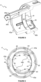
Figure 7 is a perspective view of the lock ring of the assembly ofFigures 1 to 3 ; -
Figure 8 is a perspective section view of the lock ring ofFigure 7 ; -
Figure 9 is an end view of the lock ring ofFigures 7 and8 showing its elliptical cam surface; -
Figure 10 is a perspective view of the sleeve of the assembly ofFigures 1 to 3 ; and -
Figure 11 is a perspective section view of the sleeve ofFigure 10 . - Referring now to
Figures 1 to 3 , there is shown anadjustable stopper assembly 1 for a vehicle door or hood (not shown). The assembly includes abase 2 for mounting the assembly to a vehicle, abumper 3 mounted to thebase 2 and alock ring 4 rotatable between an unlocked condition, in which thebumper 3 is movable toward thebase 2, and a locked condition, in which movement of thebumper 3 toward thebase 2 is inhibited. A core 20 projects from thebase 2 and asleeve 5 surrounds thecore 20 and is received between thebumper 3 and thebase 2. - As shown more clearly in
Figure 4 , thecore 20 is non-round, having a square cross-section in this example. Each of a pair of opposed sides of thecore 20 includes a series of outwardly projectingserrated teeth 21, which provide gripping features that will be discussed further below. Thebase 2 has a generally obround mountingportion 22 with a pair ofholes 23 through its thickness for receiving fasteners (not shown) that secure thebase 2, and therefore theentire assembly 1, to a vehicle body (not shown). Thebase 2 also has acylindrical receptacle 24 projecting from the mountingportion 22 at an acute angle. Thecore 20 is located within thecylindrical receptacle 24 and is coaxial therewith. - Turning now to
Figure 5 , thebumper 3 is generally cylindrical in shape, with aradial flange 30 at one of its ends. Theradial flange 30 includes a plurality ofshallow depressions 31 spread equally about its periphery. Thebumper 3 also includes aclosed end 32 with a circularcentral recess 33 to accommodate an injection point required for injection moulding thebumper 3. Theradial flange 30 is located at the opposite end of the bumper, which is open to provide access to afemale thread 34 within thebumper 3. Theradial flange 30 andfemale thread 34 are provided by a separate component that is overmoulded with an elastomeric material to provide aresilient bumper 3 against which the vehicle door or hood is to abut. -
Figure 6 shows an alternative bumper 3', which is similar to thebumper 3 shown inFigures 1 to 5 , wherein like features are labelled with like features followed by a '. The bumper 3' shown inFigure 6 differs from that ofFigures 1 to 5 only in that it includes an elongated recess 33' in place of the circularcentral recess 33. The elongated recess 33' originates at the centre of the closed end 32' and extends radially outwardly. This elongated recess 33' provides an indication of the radial position of the bumper 3', which is useful when making final adjustments to the position of the bumper 3' as described further below. -
Figures 7 to 9 illustrate more clearly thelock ring 4, which is generally cylindrical and includes afirst ring portion 40a received within thecylindrical receptacle 24 of thebase 2 and asecond ring portion 40b surrounding thebumper 3. Thelock ring 4 also includes a pair ofcams 41 at the junction between the first andsecond ring portions inner cam surface 42 is formed by thecams 41. Theinner cam surface 42 is non-round, in this case elliptical. - A series of inwardly projecting first stops 43 are provided by respective barbed ends of three
resilient arms 43a described in thesecond ring portion 40b. A series of inwardly projectingsecond stops 44 at are also provided by respective barbed ends of tworesilient arms 44a described in thefirst ring portion 40a, thereby providing inwardly projecting stops 43, 44 at each end of thelock ring 4. A plurality of inwardly extendingaxial ridges 45 are spaced about an inner surface of thesecond ring portion 40b. Similarly, a plurality ofaxial depressions 46 are spaced about an inner surface of thefirst ring portion 40a. - As shown more clearly in
Figures 10 and 11 , thesleeve 5 is generally cylindrical with a pair of opposedresilient arms 50 each having an outwardly projectingcam 50a and a series of inwardly projectingserrated teeth 51 adjacent its free end. Thesleeve 5 also has a pair of part-annular recessed stops 52 adjacent a first of its ends that receive and engage with the inwardly projectingsecond stops 44 of thelock ring 4. In this example, thestops 52 of thesleeve 5 and the second stops 44 of thelock ring 4 include cooperatingfrustoconical surfaces 44b, 52a. During assembly, thesleeve 5 is inserted into thelock ring 4, and so thefrustoconical surfaces 44b of the second stops 44 of thelock ring 4 provide a lead-in for urging theresilient arms 44a apart until the second stops 44 snap into engagement with the recessed stops 52 of thesleeve 5. - The
sleeve 5 is tubular, but while it is substantially cylindrical externally, thesleeve 5 includes acore receptacle 53 having a non-round cross-section, square in this example, to receive the correspondingly shapedcore 20. Externally, thesleeve 5 includes a plurality ofaxial ridges 54 spaced equally about its periphery. Theaxial ridges 54 are configured to be received within theaxial depressions 46 of thelock ring 4, thereby to inhibit rotation of thelock ring 4 relative to thesleeve 5. Thesleeve 5 also includes a male thread 55 at the second of its ends, for cooperation with thefemale thread 34 of thebumper 3. - As is most clear from
Figure 3 , thecore 20 of thebase 2 is received within thecore receptacle 53 of thesleeve 5, which itself is received within thelock ring 4 andfirst ring portion 40a of thelock ring 4 is received within thecylindrical receptacle 24 of thebase 2. Thebumper 3 is received within thesecond ring portion 40b of thelock ring 4 and thefemale thread 34 of thebumper 3 engage the male thread 55 of thesleeve 5. The first stops 43 of thelock ring 4 cooperate with theradial flange 30 of thebumper 3 to prevent thebumper 3 from being removed from theassembly 1. - The
lock ring 4 is rotatable to cause thecams 41 thereof to engage thecams 50a of theresilient arms 50, thereby to clamp the core 20 between theresilient arms 50. More specifically, theresilient arms 50 of thesleeve 5 are oriented at 90° relative to thecams 41 of thelock ring 4 when thelock ring 4 is in the unlocked condition. In this condition, theresilient arms 50 are relaxed, as shown inFigures 10 and 11 . In the locked condition, thecams 41 of thelock ring 4 engage thecams 50a of theresilient arms 50 such that thecore 20 is clamped between theresilient arms 50, as shown inFigure 3 . - Moreover, the
axial ridges 54 of thesleeve 5 engage with theaxial depressions 46 of thelock ring 4 when thelock ring 4 is in each of the locked and unlocked condition. As a result, these catch features 54, 46 inhibit rotation of thelock ring 4 out of each of the locked and unlocked conditions. - As the
lock ring 4 is rotated from the unlocked condition toward the locked condition, the sliding engagement between theinner cam surface 42 and thecams 50a of theresilient arms 50 gradually urges theresilient arms 50 inwardly, thereby to clamp the core 20 between theresilient arms 50. When thelock ring 4 is in the locked condition, theserrated teeth 51 of theresilient arms 50 engage theserrated teeth 21 of thecore 2 to prevent movement between the core 20, and therefore thebase 2, and thesleeve 5. - When the
lock ring 4 is in the unlocked condition, however, thesleeve 5 is able to slide along thecore 20, and thereby move toward or away from thebase 2. In this, unlocked condition, it is preferable that there is some engagement between theserrated teeth sleeve 5 causes theresilient arms 50 to flex slightly outwardly to allow theserrated teeth sleeve 5 along thecore 20. - The threaded engagement between the
bumper 3 and thesleeve 5 enables a fine-tune adjustment of the position of thebumper 3 relative to thebase 2 when thesleeve 5 is secured in position to thebase 2. Thedepressions 31 of thebumper 3 engage theridges 45 of thelock ring 4 as thebumper 3 is rotated relative to thesleeve 5. These catch features 31, 45 provide an audible clicking sound, which facilitates step-wise adjustment of thebumper 3 relative to thesleeve 5. - In use, the
stopper assembly 1 is mounted to the vehicle and thelock ring 4 is placed in the unlocked condition. The door or hood is then closed against thebumper 3 to urge thebumper 3 toward abase 2. This force pushes thesleeve 5 along the core 20 to a position that corresponds largely to that which is appropriate for the vehicle. The door or hood is then be opened and thelock ring 4 is rotated from the unlocked condition to the locked condition. This prevents movement of thesleeve 5 relative to thebase 2, thereby inhibiting movement of thebumper 3 relative to the base. - However and as explained above, it is common for the position of the door or hood not to be flush with a surrounding stationary structural part (for example a body of the vehicle). Fine tune adjustment of the position of the
bumper 3 may therefore be achieved by rotating it relative to thesleeve 5, as explained above. This process may be repeated several times until the door or hood is in the desired position. - The skilled person will appreciate that the elongated recess 33' of the bumper 3' of
Figure 6 provides an indication of its radial position, which may be advantageous when carrying out this fine tune adjustment. The skilled person will also appreciate from the aforementioned disclosure that thelock ring 4 andbumper 3, 3' are advantageously operable by hand with no tools. - It will be appreciated by those skilled in the art that several variations to the aforementioned embodiments are envisaged without departing from the scope of the invention. It will also be appreciated by those skilled in the art that any number of combinations of the aforementioned features and/or those shown in the appended drawings provide clear advantages over the prior art and are therefore within the scope of the invention described herein.
Claims (15)
- An adjustable stopper assembly (1) for a vehicle door or hood, the assembly comprising a base (2) for mounting the assembly to a vehicle, a bumper (3, 3') mounted to the base (2) and a lock ring (4) rotatable between an unlocked condition, in which the bumper (3, 3') is movable toward the base (2), and a locked condition, in which movement of the bumper (3, 3') toward the base (2) is inhibited.
- The adjustable stopper assembly (1) of claim 1 comprising a core (20) projecting from the base (2) and a sleeve (5) between the bumper (3, 3') and the base (2) and surrounding the core (20), wherein the sleeve (5) clamps the core (20) when the lock ring (4) is in the locked condition, thereby to inhibit movement of the bumper (3, 3') along the core (20).
- The adjustable stopper assembly (1) of claim 2, wherein the lock ring (4) surrounds the sleeve (5) and rotation of the lock ring (4) causes an inner cam (41) of the lock ring (4) to urge a resilient arm (50) of the sleeve (5) into engagement with the core (20) when the lock ring (4) is rotated from the unlocked condition to the locked condition
- The adjustable stopper assembly (1) of claim 3, wherein the inner cam (41) of the lock ring (4) comprises a non-round inner surface (42) that engages the resilient arm (50) on rotation of the lock ring (4) relative to the sleeve (5).
- The adjustable stopper assembly (1) of claim 3 or claim 4, wherein the resilient arm (50) is one of a pair of opposed resilient arms (50) movable into engagement with the core (20) when the lock ring (4) is rotated from the unlocked condition to the locked condition, thereby to clamp the core (20) between the resilient arms (50).
- The adjustable stopper assembly (1) of any one of claims 2 to 5, wherein the core (20) comprises a gripping feature (21) for cooperation with a corresponding gripping feature (51) of the sleeve (5) to inhibit movement of the sleeve (5) along the core (20) when the lock ring (4) is in the locked condition.
- The adjustable stopper assembly (1) of any one of claims 2 to 6, wherein the bumper (3, 3') is threadedly connected to the sleeve (5) for further adjusting its position relative to the base (2).
- The adjustable stopper assembly (1) of claim 7, wherein the lock ring (4) surrounds the bumper (3, 3') and the sleeve (5) and includes a first stop (43) for cooperating with a stop (30) of the bumper (3, 3') and a second stop (44) for cooperating with a stop (52) of the sleeve (5), thereby to retain the bumper (3, 3') on the sleeve (5).
- The adjustable stopper assembly (1) of claim 8 comprising a plurality of catch features (45, 31) between the lock ring (4) and the bumper (3, 3') for providing a step-wise threaded adjustment of the bumper (3, 3') relative to the sleeve (5).
- The adjustable stopper assembly (1) of any one of claims 7 to 9, wherein the bumper (3') has an indicator (33') for indicating a rotational position thereof relative to the base (2).
- The adjustable stopper assembly (1) of any preceding claim, wherein the lock ring (4) is operable by hand with no tools.
- The adjustable stopper assembly (1) of any preceding claim, wherein the core (20) and a core receptacle (53) of the sleeve (5) that receives the core (20) have a cooperating non-round shape to inhibit relative rotation therebetween.
- The adjustable stopper assembly (1) of any preceding claim comprising a plurality of catch features (54, 46) between the sleeve (5) and the lock ring (4) for inhibiting rotation of the lock ring (4) out of at least one of the locked and unlocked conditions.
- The adjustable stopper assembly (1) of any preceding claim, wherein the bumper (3, 3') has a closed end (32, 32') for cooperating with the vehicle door or hood.
- A method of adjusting a vehicle door or hood stopper assembly (1), the method comprising closing a door or hood to cause a bumper (3, 3') of the assembly (1) to move toward a base (2) to which it is adjustably mounted by an adjustment means (20, 5) and rotating a lock ring (4) to lock the adjustment means (20, 5) to inhibit movement of the bumper (3, 3') relative to the base (2).
Applications Claiming Priority (1)
| Application Number | Priority Date | Filing Date | Title |
|---|---|---|---|
| EP23161254 | 2023-03-10 |
Publications (1)
| Publication Number | Publication Date |
|---|---|
| EP4428332A1 true EP4428332A1 (en) | 2024-09-11 |
Family
ID=89723192
Family Applications (1)
| Application Number | Title | Priority Date | Filing Date |
|---|---|---|---|
| EP24153989.9A Pending EP4428332A1 (en) | 2023-03-10 | 2024-01-25 | Adjustable stopper |
Country Status (1)
| Country | Link |
|---|---|
| EP (1) | EP4428332A1 (en) |
Citations (5)
| Publication number | Priority date | Publication date | Assignee | Title |
|---|---|---|---|---|
| US20020003993A1 (en) * | 2000-07-06 | 2002-01-10 | Takahide Ichimaru | Damper device |
| WO2002008554A1 (en) * | 2000-07-20 | 2002-01-31 | Adam Opel Ag | Adjustable damping element and method for adjustment thereof |
| FR2946383A1 (en) * | 2009-06-09 | 2010-12-10 | Itw De France | Adjustable stopper for use in motor vehicle, has blocking member provided in retainer in locked position, where retainer includes external tube and inner rod, and bush section surrounds rod and surrounded by tubular section |
| WO2015055921A1 (en) * | 2013-10-14 | 2015-04-23 | A Raymond Et Cie | Buffer device having a self-adjusting abutment |
| WO2022190744A1 (en) * | 2021-03-12 | 2022-09-15 | 株式会社パイオラックス | Stopper device |
-
2024
- 2024-01-25 EP EP24153989.9A patent/EP4428332A1/en active Pending
Patent Citations (5)
| Publication number | Priority date | Publication date | Assignee | Title |
|---|---|---|---|---|
| US20020003993A1 (en) * | 2000-07-06 | 2002-01-10 | Takahide Ichimaru | Damper device |
| WO2002008554A1 (en) * | 2000-07-20 | 2002-01-31 | Adam Opel Ag | Adjustable damping element and method for adjustment thereof |
| FR2946383A1 (en) * | 2009-06-09 | 2010-12-10 | Itw De France | Adjustable stopper for use in motor vehicle, has blocking member provided in retainer in locked position, where retainer includes external tube and inner rod, and bush section surrounds rod and surrounded by tubular section |
| WO2015055921A1 (en) * | 2013-10-14 | 2015-04-23 | A Raymond Et Cie | Buffer device having a self-adjusting abutment |
| WO2022190744A1 (en) * | 2021-03-12 | 2022-09-15 | 株式会社パイオラックス | Stopper device |
Similar Documents
| Publication | Publication Date | Title |
|---|---|---|
| US12012049B2 (en) | Fastening clip device configured to secure a door module to a door frame of a vehicle | |
| EP1449273B1 (en) | Antenna mounting assembly for cars | |
| US5688093A (en) | Ejecting quick-connect fastener | |
| US8282329B2 (en) | Fastener for securing together two panels | |
| JP2002516962A (en) | Car deck lid bumper | |
| US20200018334A1 (en) | Clamping apparatus | |
| US5795122A (en) | Adjustable quick connect fastener for accommodating panels of various thicknesses | |
| US10689895B2 (en) | Device for adjusting the elevation of a piece | |
| US9009876B2 (en) | Drain cover with locking mechanism | |
| US20190301222A1 (en) | Device for adjusting the elevation of a piece | |
| US8757952B2 (en) | Fastener for securing together two panels | |
| US12241293B2 (en) | Quick install method and apparatus for door locks | |
| WO2012154037A1 (en) | Pipe clip | |
| JP5986023B2 (en) | Barrel polishing equipment | |
| EP2615708B1 (en) | Installation box | |
| US20180100605A1 (en) | Method for fastening a conduit on a support by means of freely adjustable captive flanges | |
| US10934758B2 (en) | Desensitized adjustable bumper | |
| US20220290477A1 (en) | Hinge for a removable vehicle door | |
| US11834891B2 (en) | Spacer device | |
| EP2682656B1 (en) | Pipe clip with spring washer | |
| JP2007530879A (en) | Device for fixing to a support member with screw bolts | |
| US11293204B2 (en) | Door handle including dual hinged sound dampening flap feature | |
| US8656806B2 (en) | Cam system having compliant follower | |
| US20260055788A1 (en) | Clamping assembly and method for installing an accessory on a connecting interface | |
| US20020095758A1 (en) | Fuel damper removal tool |
Legal Events
| Date | Code | Title | Description |
|---|---|---|---|
| PUAI | Public reference made under article 153(3) epc to a published international application that has entered the european phase |
Free format text: ORIGINAL CODE: 0009012 |
|
| STAA | Information on the status of an ep patent application or granted ep patent |
Free format text: STATUS: THE APPLICATION HAS BEEN PUBLISHED |
|
| AK | Designated contracting states |
Kind code of ref document: A1 Designated state(s): AL AT BE BG CH CY CZ DE DK EE ES FI FR GB GR HR HU IE IS IT LI LT LU LV MC ME MK MT NL NO PL PT RO RS SE SI SK SM TR |
|
| STAA | Information on the status of an ep patent application or granted ep patent |
Free format text: STATUS: REQUEST FOR EXAMINATION WAS MADE |
|
| 17P | Request for examination filed |
Effective date: 20250306 |